have doughnut
TRANSCRIPT

r " i. t
-:- .~('•!-r•;:- ~"~.._·. ~ ....... , :
rc.:> ~·' '. ' ,......-., .. ..;~

I I
: I l :l I I

•
•
GROUP· I
HAVE DOUGHNUT-TACTICAL
VOLUME II (U)
FTD-CR-20-13-69-INT, VOL II
DIA TASK NO. T65-20-2
1 August 1969
This report is classified because it contains intelligence information collected on a foreign aircraft and presents tactical performance comparisons of the foreign aircraft to USAF and USN aircraft.
WARNING THIS DOCUMENT CONTAINS INFORMATION AFFECTING THE NATIONAL DEFENSE OF THE UNITED STATES WITHIN THE MEANING OF THE ESPIONAGE LAWS, TITLE 18 U.S.C. SECTIONS 793 AND 794. ITS TRANSMISSION OR THE REVELATION OF ITS CONTENTS IN ANY MANNER TO AN UNAUTHORIZED PERSON IS PROHIBITED BY LAW.
This is a Department of Defense Foreign Materiel Report prepared by the Foreign Technology Division, Air Force Systems Command, with contributions from TAC, ADC and the Navy, for the Defense Intelligence Agency.
NO FOREIGN DISSEMINATION
(This page is unclassified)
Excluded from avtomatle down;radlnp and doelaulfleatlon, 69TDA-736J
(F£VEHSE BLA!JK)

i I'
i I
I I
ill
·.
! 'll.' I !
:1.11 I
!
I
I I
: ::: iiI I I I,
t II I I
II i:

•
•
•
PROJECT RAVE DOUGHNUT
-- "-·· ' F;~::Z:J;~-~';;·~;t1i!:l!!!1.f;~:f::i~i:j;_~~;;;--:~~-::· -,. •... , .. -
MIG-21-Fl3 THE RAVE DOUGHNUT AIRCRAF!'
(S-Gp-3)
111
(REVERSE BLANK)

~ ~, .. ·. ;-·'i.,;!_,. 1 . . ''. ~~·
i! I i: I I
I! I I
• I I I . . I
II. I i• I I
, I
,I
I
I
I
, I
I
I,
t I ! '
I I
I i
i I I 1.
II
I
I ,j I I' I.
I
I
I I
I i
II
~ ; I
! I ! I
i i
! : i

•
•
•
ABSTRACT
(S/NFD) This report presents the results of a tactical evaluation of a Soviet FISHBED E (MIG-21'-13) aicraft performed under the management of the Foreign Technology Division, Wright Patterson AFB, Ohio. The evaluation consisted of comparative and tactical flights against both USN and USAF first.line fighter aircraft. Results of the performance and flight test evaluation, system and subsystem characteristics, design features and technological information acquired from the exploitation are presented in :MID Dooument CR-2o-13-69 !NT Volume I -Technical. Basic agreement between published estimates and the exploitation results was found and the current practiced tactical maneuvers against the ~ISHBED E were confirmed and revalidated •
69TDA-7J0

r .
I,
I
' I
I I
II I I
' I, ' 'I
' I I ! ! '
! t
I
I
I
i
i; ! •
I
I!
~ I' ! I
I
I, I
I
:I : ,, , I
-

•
•
•
TABLE OF CONT3NTS
Page No.
A'3'l']'1RACT • • • • • • • • • • • • • • • • • • • • • • • • • • • • • • v
SUMMARY • • • • • • • • • • • • • • • • • • • • • • • • • • • • • • xi
SUPPLEMENTS 1 - 3
1. TACTICAL AIR CO!.TllAND EVALUATION • • • • • • • • • • • • 1-1 to 1-132
2.
Glossary ••• • • • • • • • • • • • • • • • • • • • • • 1-1 to 1-2
Introduction • • • • • • • • • • • • • • • • • • • • • • • • 1-3
Description of Test Item • • • • • • • • • • • • • • • • • • 1-3
Objectives • • • • • • • • • • • • • • • • • • • • • • • • • 1-3
Scope of the Test • • • • • • • • • • • • • • • • • • • l-3 to 1-7
Deficiencies and Limitations • • • • • • • • • • • • • • 1-7 to 1-8
Conclusions • • • • • • • • • • • • • • • • • • • • • • 1-8 to 1-16
Becommendations • • • • • • • • • • • • • • • • • • • • 1-16 to 1-19
Test Environment and Procedures • • • • • • • • • • •• 1-19 to 1-24
Test Results and Discussion • • • • • • • • • • • • •• 1-24 to 1-47
Annex A Tactical Mission Summaries • • • • • • • • 1-48 tCI 1-110
Annex B ~.:aintenance Summaries • • • • • • • • • • • 1-111 to 1-122
Attachment 1
Attachment 2
Attachment 3
Attachment 4
Attachment 5
Test Aircraft • •
F-4D (Aircraft #1)
F-4D (Aircraft ~)
• • • • • • • • • 1-112 to 1-113
• • • • • • •• 1-114
• • • • • •
F-105D • • • • • • • • • • • •
•• 1-115 to 1-117
•• 1-118 to 1-119
F-105F • • • • • • • • • ••••• 1-120 to 1-122
Annex C ,Cockpit Evaluation Summaries • • • • • • • 1-123 to 1-126
Annex D 71'eapon ::;ffects • • • • • • • • • • • • • • 1-127 to 1-132
U.S. NAVY EVALUATI 01i • • • • • • • • • • • • • • • • • • 2-1 to 2-131
References • • • • • • • • • • • • • • • • • • • • • • • 2-2 to 2-4
Previously Known Data • • • • • • • • • • • • • • • • • 2-4 to 2-5 vii
... -~ ~
69TD.A- 7363

Figure
1-1
1-2
1-3
TA~LE OF CONTENTS (Cont)
Acronyms and Abbreviations • • • • • • • • • • • • • • •
Pap:e ~TQ •
• 2-6 to 2-9
Description of Material • • • • • • • •••
Pur?oae of the Test
Conduct of the Test
• • • • • • • • • • • •
••••••• 2-10 to 2-17
• •••••• 2-18
• • • • • • • • • • • • . . . ' . . . • 2-18 to 2-20
Results and Di.scus.sion • • • • • • • • • • • • • • • • • • 2-20
Operational Applications •• • • • • • • • • • • • • • • • 2-4t:i to 2-60
Conclusions • • • • • • • • • • • • • • • • • • • • • • • 2-61 to 2-62
Recommendations • • • • • • • • • • • • • • • • • • • • • 2-63 to 2-64
Basic Conclusions • • • • • • • • • • • • • • • • • ••• 2-65
Daily Maintenance and Project Flight Summary • • • • • • • 2-66 to 2-73
Mission Summaries • • • • • • • • • • • • • • • • • • • • 2-74 to 2-111
AIR DEFENSE COMiviA.ND EVALUATION • • • • • • • • • • • • • • 3-1 to 3-24
In troduc ti on • • • • • • • • • • • • • • • • • • • • • • • 3-1
Objectives • • • • • • • • • • • • • • • • • • • • • • • 3-1
Results • • • • • • • • • • • • • • • • • • • • • • • • • 3-2 to 3-24
LIST OF ILLU$TRATIONS
FISHBED E • • • • • • • • • • • • • • • • • • • • • • • • 1-5
Seat Flaps • • • • • • • • • • • • • • • • • • • • • • • • 1-9
Cockpit Area • • • • • • • • • • • • • • • • • • • • • • • 1-9
viii 69TDA-7363
~·
•
•
•

• Fisur~
1-4
1-5
1-6
1-7
1-8
1-9
2-1
2-2
2-3
2-4
2-5
• 2-6
2-7
2-8
2-9
2-10
2-11
2-12
2-13
2-14
2-15
2-16
2-17
•
LIST OF ILLUSTRATIONS (Cont)
Page No.
1ITG-21 Pilot Positioning • • • • • • • • • • • • • • • • • • 1-44
Ejection Sequence • • • • • • • • • • • • • • • • • • • • • 1-45
Weapon Effects • • • • • • • • • • • • • • • • • • • • • •• 1-129
Weapon Effects • • • • • • • • • • • • • • • • • • • • • • • 1-130
Weapon Effects • • • • • • • • • • • • • • • • • • • • • • • 1-131
Weapon Effects • • • • • • • • • • • • • • • • • • • • ••• 1-132
FISHBED E Plan Form • • • • • • • • • • • • • • • • • ••• 2-10
rrrc~21 Pilot Seating Position • • • • • • • • • • • • • • • 2-22
Instr·~ent Panel • • • • • • • • • • • • • • • • • • • • • • 2-24
Throttle 0uadrant • • • • • • • • • • • • • • • • • • ••• 2-26
~jection Sequence • • • • • • • • • • • • • • • • • • • • • 2-27
Protective Armor •• • • • • • • • • • • • • • • • • •
Smoke Emission • • • • • • • • • • • • • • • • • • •
• • • • • • • • • • • • • • • • • • ?.~IG-21 Vn Diagram
MIG-21 Vulnerability • • • • • • • • • • • • • • • • •
MIG-21 and F-4 in Flight • • • • • • • • • • • • • • •
~ITG-21 and F-4 Vn Diagram • • • • • • • • • • • • • •
F-4 Compressor Modulation • • • • • • • • • • • • • •
1UG-21 and F-4 Compressor Modulations • • • • • •
F-8 Target Blip and MIG-21 Compressor Modulation •
UIG-21 Comnressor ~.!adulation - EXPended ••••• Velocity Display and Real k~G-2l.Velocity Target
• •
• •
• • • •
••• 2-2A
• • • 2-30
• • • 2-30
• • • 2-33
• • • 2-33
• • • 2-34
• •• 2-39
• • • 2-39
• • • 2-40
• • • • • • 2-40
• • • • • • • • • • • • • • • • • 2-41 ~.~G-21 a:1d F-8 in F1i.ght
1:IG-21 and F-8 Vn Diagram • • • • • • • • • • • • • • • •• 2-43
69?DA-7363

Tn.ble
1-1
1-2
1-3
2-1
2-2
LIST OF ILLUSTRATIONS (Cont)
World Wide FISHBED AOB • • • • • •
FISHBED E General Characteristics
• • • • • • • • • • • • •
Page UQ.a.
• 1-4
• • • • • • • • • • • • • • 1-6
Project Missinn Summary • • • • • • • • • • • • • •
Summary of Scheduled and Cancelled Flights • • • • •
Detection Ranges • • • • • • • • • • • • • • • • • •
• •
• •
• •
• • • 1-25 to 1-30
• • • 2-19
• • • 2-36
69TDA-7363
•
•
•
•
•
•
(S/WFD) The purpose of this report is to present the results of a taotioal evaluation of a FISHBED E (MIG-21~13) aircraft. The report is intended toa
(1) Present to Commanders and oombat members an evaluation of the effectiveness of existing tactical maneuvers by USAF and USN oombat aircraft and associated weapons systems against the MIG-21,
(2) To exploit the tactical capabilities and limitations of the MIG-21 in an air-to-air environment,
(3) To optimize existing tactics and develop new taotios as necessary to defeat the MIG-21,
(4) To evaluate the design, performance and operational oharaoteristios of the MIG-21.
BACKGROUND
(S/NFD) The mission of the Foreign Technology Division inoludes the acquisition and evaluation of foreign materiel to provide information of scientific and teohnioal value to our national intelligence community as well as Air Foree and Navy research and development organizations, thus enabling our oombat orews to best perform their assigned missions. This report oonoerns a project to obtain such information designated Projeot Have Doughnut.
(S/NFD) The e%ploitation of the MIG-21 airoraft was assigned a high priority sinoe it has been widely exported and deployed to most nations within the communist sphere of influence and is in combat in SEA.
(S/NFD) Comprehensive data on the MIG-21 aircraft is contained in (U) Fishbed Weapon System, ST-CS-09~27-69, dated 23 Sep 1969, class~fied Secret and Have Doughnut Volume I - Teohnio~ FTD-CR-2Q-13-69 INT, classified Secret Bo Foreign Dissemination. The Have Doughnut project was initiated to provide substantiating and supplemental information to that published in the FTD/DIA ~tudy as well as to validate current tact~cal maneuvers used by USAF and USN combat airerews against the MIG-21 aircraft •
xi 69TDA-7363
REVERSE BLANK

•
•
•

•
•
•
SUPPLEMENT 1
PROJECT HAVE DOUGHNUT
REPORT OF TACTICAL
EVALUATION OF PROJECT AIRCRAPT
AS DETERMINED :BY
TBE UNITED STATES AIR FORCE
TACTICAL AIR COMMAND
(This page Unclassified) 69TDA-7363

•
•
•

•
•
•
GLOSSARY
1. Adverse Yaws The tendency of an aircraft to yaw away from the applied aileron. Induced by rolling motion and aileron deflection, usually greatest at high angle of attack and full aileron deflection.
2. ~imum Rate Turn: That turn at which the maximum number of degrees per second is achieved.
3. Maneuverability• The ability to change direction and/or magnitude of the velocity vector.
4. 1¥qimum Performance! Tb.e best possible performance without exceeding aircraft limitations.
5. Energy Maneuyerability; A concept used to determine total inflight performance by measuring instantaneous and sustained maneuverability of an aircraft through its envelope.
6. Maneuyering Energya The ability to perform maneuvers as a result of energy possessed.
7. Energy Leyel (Es)a Total energy state possessed for a given combination of altitude and airspeed (Mach) •
B. Energy Rate (Pi)a A measure of the ability to gain or lose energy in terms of altitude and airspeed or combinations thereof.
9. V-N Dia.sn-am1 A plot of load factor versus velocity used to provide a measure of instantaneous maneuverability.
10. Lethal Envelope: The vulnerable envelope emanating from the target aircraft.
11. Defensive Turn; The basic defensive maneuver designed to prevent an attacker from achieving a launch or firing position.
12. Hard Turn (Single Direction Turn)a A planned defensive turn in which the intensity of the turn is governed by the angle-off, range and closure of the attacking aircraft.
13. Break: A maximum performance defensive turn into the attacker to instantly destroy an attacker's tracking solution.
14. TCA- Angle-Off (Aspect Angle), The angle between the defender's line of flight and the attacker's line of sight measured in degrees (Track Crossing Angle).
15. Separation• Distance between an attacker and defender. Can be either lateral or longi~~dinal •
1-1 (This page is Unclassified)
... • w .. ..., #<4...'f' ..
~~: ·~: , ~ \',I-~ > ~ , I•; ~ ~~ ~

-------------------------------------------~----------------
16. Scissors! A defensive maneuver in which a series of turn reversals are executed in an attempt to achieve the offensive after an overshoot by the attacker.
17. Ji~ing ¥aneuyera A series of rapid turn reversals or abrupt changes of rol~pitch angle at random intervals, to prevent an attacker from achieving a tracking solution. Usually employed with little load factor while gaining lateral separation.
18. Diving Spiral! A near vertical accelerating dive using G and roll rate to destroy an attacker's tracking solution and gain lateral separation.
19. High Speed Yo-Yoa An offensive maneuver performed to maintain nose-tail separation and prevent the possibility of becoming engaged in a scissors maneuver.
20. Lufberya A circular tail chase.
21. Low Speed Yo-Yo! A maneuver employed to facilitate closure and at the same time allow an attacker to remain inside an opponent's turn radius.
22. Closure (Relatiye Velooity)a The time rate of change of distance along the line of sight between aircraft.
23. Element! The basic fighting unit (two aircraft).
24. Fluid Elementa The second or supporting element in fluid tour formation, flying in a high or low element position.
25. J&Ml Air combat maneuvers.
26. DCM1 Defensive combat maneuvering.
27. Maximum Performance ¥aneuvering Envelope J A maneuvering region for the wingman in whioh optimum visual coverage and mutual support may be achieved in maximum performance maneuvers.
28. Defeneiye Split! A controlled separation of a defensive element in different planes used in an attempt to force the attackers to commit themselves to one of the defenders.
39. In-Trail! Individual aircraft, one behind the other.
30. In-Train! Elements or flights, one behind the other.
l-2
(This page is Unclassified)
•
•
• ---- --------------------------

•
•
•
-----
1. INTRODUCTION
(S/NFD)Tactical Air Command, in joint participation with United States Navy and other government agencies, conducted an analysis of the MIG-21~13 (FISHBED E) day fighter weapons system. The FISHBED is deployed widely throughout the world (Table 1-1) and represents a formidable threat to US tactical forces. TAC pilots evaluated FISHBED E as a total weapons system in a tactical environment and compared it, operationlly, with selected USAF aircraft.
2. DESCRIPTION OF TEST ITEM;
A. (s) The MIG-21P-13, designated FISHBED E, is a single-place, clear air mass, high altitude, point interceptor, weapons system. The aircraft is capable of performing a secondary role of ground attack and incorporatesair-to-ground armament systems. Initial MIG-21 prototype design was started in 1952 and design modification for the FISHBED E was initiated in 1959. This variant provided improved stability. (See Fig 1-1) A resume 1 of general performance characteristics is shown in Table 1-2.
B. (s) The MIG-21 is being used in the Southeast Asia environment primarily as a medium and low altitude interceptor and day fighter. United States strike force fighter bombers are intercepted . by the MIG-21 which is initially GCI veetored into the rear hemi~phere for a highspeed, single-pass attack. Prolonged engagements have occurred, forcing the MIG-21 to operate as a day fighter at medium and row altitudes. Only limited use has been made of the MIG-21 in the high altitude, point intercept role, due to tactics of 1SAF aircraft.
c. (U) Detailed description of the FISRBED E weapons system is available in ST..:.CS-09-:-27-69 technical study, and other FTD publications.
3. OBJECTIVES
(S/NFD) To determine the tactical capability of the complete FISHBED E (MIG-21F-13) weapons system. The aircraft will be evaluated in a tactical environment as a day fighter, clear air mass interceptor, and as an air-to-ground attack aircraft. Comparative operational analysis with selected US operational aircraft will validate or formulate optimum US air combat maneuvering techniques and will define the tactical capabilities, limitations, and deficiencies of the FISHBED E.
4. SCOPE OF THE TEST
(S/NFD) The scope of this test included, but was not limited toa
A. Defining the offensive and defensive tactical capability of the FISHBED E total weapons system in an air-to-air environment. Comparative tactical analysis will be accomplished with the 1ITG-21 and the following airorafta
1-3

TA:SLE 1-1
WQELI !~nE l~SB~~ AQ~
{S-Gp-1)
MODEL NATIONAL AIR FORCES c/E D/F
'Bulgaria 22 14 Czechoslovakia 42 76 E Germany 76 141 Hungary 60 30 Poland 43 68 Rumania 42 10 Yugoslavia 36 20 Russia 717 Communist China 33 North Korea 1 10 North Vietnam Indonesia 17 Cuba 33 27 Syria 1 Iraq 11 13 India United Arab Republic 36 Afganistan
417 1162
Soviet Air Forces in European Communist Countries
E Germany Hungary Poland
TOTAL FISH:SED - WORLD WIDE
~· •••
284 111
....m. 506
1-4
•
.m TOTAL
36 16 134
217 90
111 52 56
717 13 46 11 22 6 6
17 60 • 1 24
64 64 72 108 ~ __l2_
214 1793
284 111 ill
506
2299
•

•
•
•
Fig 1-1 FISHBED E (S-Gp-3)

TABLE 1-2
FISHBED E GE11E:::?.AL CHARACTERISTICS
(S-Gp-1)
Configuration: Clipped delta wing planform with swept tail surfaces •
.lliJ!s i on :
Primary- Clear air mass, high altitude point interceptor Secondary - Ground attack and tactical reconnaissance
Pronulsion: One type, R-37F axial flow turbojet with afterburner ·thrust 12,650 pounds (max afterburner), 8,640 pounds (maximum dry)
Armame;ni:
Gun- One 30mm cannon with 60 round capacity !.!issiles - Two ATOLLS Rockets - Thirt;y-t\"10 57 mm FFARs (two pod.s) Bombs - Total bomb load on all three stations,
D;men§ions:
'.Ving Span - 23.47 feet Length- (Without pitot boom) 44.2 feet Height - 13.5 feet Weight- Empty: 11,017 pounds
Truceoff: 17,286 pounds !.!a:x:imurn: 18 ,072 pounds
Performance:
:Maximum 1-:B.ch - 2.05 Service Ceiling- 57,500 ft. Strike Radius - 370 NM with external fuel
St:r-uctwal Limits:
1.1aximum !.!a.ximum :C!a.ximurn T.~ximum
Fuel Lorui:
Load Faotor Indicated Airspeed Indicated Mach Tiynamic Pressure
Internal - 4,600 lb Genterline Tank - 880 lb
w/o External.Stores
8 G 595* kt 2.05 2 1200 lb/ft
* ~elaw 15000 ft, above 15000 ft 640 kt
1-6
3,300 pounds
w/External Stores
6 G 595* kt 1.8
1200 'lb/ft2
•
•
•

•
•
•
(1) F-4C/D/E
(2) F-105D/F
(3) F-lllA
(4) F-lOOD
(5) F-104D
(6) F-5N
(7) RF-101 (Defensive Only)
(8) RF-4C
(9) B-66 (Defensive Only)
B. Identifying the operational limitations and deficiencies of the FISHBED E systems and subsystems, to include:
(1) Aircraft performance
(2) Aircraft stability and control
(3) Armament, lead computing gun sight, and radar ranging system.
(4) Cockpit environment
c. Defining optimum air combat maneuvers (ACM) to be employed by US tactical aircraft in defensive or offensive situations to defeat the F!SHBED E.
D. Validating recommended ACM prescribed in current tactical manuals and publicat±ons ••
E. Determining the air-to-ground attack capability, deficiencies and limitations of the FISHBED E weapons system.
F. Iden~ifying those desirable design features of tactical significance incorporated in the MIG-21F-13 aircraft.
5. DEFICIENCIES AND LIMITATIONS:
(sj!rFD) Tactical limitations and deficiencies of the FISHBED ~are:
A. Poor Forward and Rearward Visibility. Forward visibility through the sight combining glass, bulletproof glass slab, and forward windscreen limits visual target detection. F-4 and F-105 ~ype targets normally are acquired at three to five miles range •
1-7

Rearward visibility is restricted by the seat flap (Figure 1-2 and 1-3), narrow canopy, and aircraft structure to an area outside a 50-degree tail cone.
B. Low Q Limit. Below 15,000 feet, the aircraft is limited to . 98 IMN, or 595 KIA.S. Airframe buffet is severe at and above these airspeeds and the aircraft is unuseable as a weapons system.
C. Weapons System. The 30rnm cannon · capacity is limited to 60 rounds, and severe pipper jitter precludes tracking corrections during cannon firing. The optical, lead computing, gyroscopic sight precesses excessively, and target tracking is impossible over 3 Gs. The Range-Only Radar is susceptible to chaff and electronic jamming.
D. High Longitudinal Control Forces. Above approximately 510 KIAS, below 15,000 feet, the pilot experiences high stabilator control forces and cannot command a high pitch rate.
E. Airspeed Bleed-off. At high G loads, the MIG-21 airspeed bleed-off is excessive. This does, however, improve the turn radius.
F. Engine Response. Engine acceleration in response to throttle movement is extremely poor. During ground operation,l4 seconds are required to increase the engine speed from idle to full military power. Formation flight is difficult, requiring combined use of speed brakes and throttle movement.
G. Afterburner Puff. At altitudes above 15,000 feet, the engine of the FISHBED E produces a white puff of unburned fuel as afterburner power is engaged and disengaged.
H. Directional Stability. Directional stability is poor. During air-to-ground attacks, if turbulent flight conditions exist, excessive pilot effort is required for precise target tracking.
6. CONCLUSION§.
(S/NFD) The FISHBED E has an excellent operational capability in all flight regimes. However, performance is limited below 15,000 feet, due to severe airframe buffeting which occurs above .98 IMN, or 595 KIAS. Heavy longitudinal control forces are encountered at 510 KIAS and above, making high pitch rates difficult or impossible to achieve. Forward visibility through the combining glass, bulletproof slab, and windscreen is severely degraded and the rear seat flap (Figure 1-3), narrow canopy, and aircraft structure reduce rearward visibility. Armament is adequatef however, the 30mm cannon is limited to 60 rounds total capacity and considerable pipper jitter occurs during firing. The tracking index drifts off the bottom of the windscreen when tracking targets in excess of 3 Gs. Airspeed bleed-off during high G turns is excessive and engine
l-8
•
•
•

•
•
•
Fig l-2 Seat Flap (S-Gp-1)
)':;'1• - ~
-~g l-; Co:kp~t A~ea (S-Gp-=:_)
a· r-9 ._. ll.vditi.
.'¢~' .. -<,. . ,.. ·' f
.. 4

resnonse is noor.
A. Campara ti ve Tactical Anal;r!":is
(1) F-4 and ?ISH3ZD E:
(a) The F-4 has the capability to control an engagement below 15,000 feet by exploiting the MIG-21 airspeed limitation and airs~eed ble~d-off characteristic at high G. By orientinG an a~tack towards the FISHBED C's blind cone in lag pursu1t type maneuvering, and b;r t)pera t-ing in thP. vertical during ACH, the F-4 can defeat ~he liiG-21.
(b) AcceJ.eration Comparison. Acceleration performance ')f the 'F-4 is superior in military and afterburner -power up to 30,000 feet. A significant advantage is apparent in military power and a slight advantage wa~ demonstrated in afterburner power. Below 15,000 feet, the F-4 can easily accelerate to above the usable airspeed ( 595 KIAS, or • 98 nnn of the FI3HB3D E.
(c) Zoom Comparison. The P.-4 has a significant advantage in military power zoom performance fr•m low altitude UTJ to 30,000 feet. It has a slight advantage over the MIG-21 in afterburner pow~r zoon capability, up to 20,000 feet.
(d) Turn Comparison. The MIG-21 has more instantaneous G available than the F-4 at any given airspeed up to the limit load factor of the aircraft. ~he MIG-21 loses airspeed more ra~idly during high G maneuvering than the ~4, and the subsonic, thrustlimited, turninc performance of the MIG-21 was about one-fourth G less than shown on current energy maneuverabili t~r charts.
(2) F-105 and FISRB~D E:
(a) ~he F-105 should nress an offensive attack only if an initial rear hemisphere advantage exists. Prolonged maneuverinc en.;-agemen ts should be avoided. The airspeed limit of the r.UG-21 below 15,000 feet can be easily exceeded by the F-105 if defensive separation is required. Lag pursuit offensive maneuvering to the ~nG-21 1 s blind cone, m:..1tual flight support, and hit-and-run tactics should be emTJloyed b'r the F-105.
(b) Acceleration Comparison. The F-105, in military and afterburner power, closely matches the MIG-21 in acceleration nerforman~e u~ to 15,000 feet altitude from subsonic airspeed to 1.05 TI:J:T. The F·l05 can easily accelerate to above .98 IMN, or 595 Y.IA'3, below 15,000 feet and exceed the airspeed limit of the ?I E33:!:> S.
(c) 1'urn Comparison. ThA :.nG-21 has a distinct advantage in turn capability at all airspeeds and altitudes. The F-105,
1-10
•
•
•

•
•
•
therefore, should utilize hit-and-run tactics, and avoid :prolont;ed turning eneagements with the MIG-21.
(d) Fire Control and Armament. The F-105's air-tc-air missile firing capability is equal to that of the UIG-21. Rov;ever, the F-105 has a superior eun system with its higher cyclic rate and better eunsight system.
(e) APR-25 RHA'N. The APR-25 RHA~7 equipment will not :provide sufficient warning for the F-105 pilot to negate a missile attack by the FISH'BED E.
(3) F-lllA and FISH3ED E
(a) The F-111 should avoid maneuvering eneagements with the !.~IG-21 9 since energy loss during prolonged maximum performance maneuvering is prohibitive and DC?.~ :potential is lost.
(b) Acceleration Gomparison. The J.~IG-21 has superior acceleration performance from subsonic speed to the maximu~ Q limit at altitudes below 15,000 feet. The F-111 has a definite advantage above the • 98 n.rn, or 595 KIAS.
(c) Turn !Jomparison. The ~UG-21 has superior turn capabili t.v at all altitudes and airspeeds and the F-111 should not attempt to engage in a turning fight with the !.~IG-21 at any altitude •
(4) F-lOOD and FISRBED E:
(a) The F-100 should avoid maneuvering engagements with the 1tiG-21. Effective DC1.~ is possible by accelerating beyond the • 98 TI.I'}~, 595 KIAS, limit of the !HG-21 below 15,000 feet. Hit-and-run attacks can be accompljshed and lag pursuit maneuvering to the blind area is most effective. Visual scan and mutual support are essential.
(b) Acceleration Performance. The !.:IG-21 has a significant advantage over the F-100 in both military and afterburner acceleration in all flight regimes.
(c) Turn Comparison. The UIG-21 has a significant advantage in turn capability at all airspeeds and altitudes. Therefore, the F-100 should not attempt to defeat the r.ao-21 in a prolonged turning engagement. Hit-and-~~n tactics are effective, providint; the ?-lOC airspeed is kept well above 450 KIAS.
(d) Fire Control and Armament. The F-100 missile capa::. i:!.i t;;• is appro.x:imah:::.:r eC!ual :o the ~IG-21 'a, although the A:m-9 ca:;:a.c:. ".::; is greater. Radar ranging of tee ~HG-21 in missile mode, co:nbined
l-11

with the enunciator lights for "In Range" and "Over G" equalize this missile capacity difference. The four 1~39, 20mm cannons and the optical sight system of the F-100 are superior to the MIG-21's gun system.
(5) F-104D and FISHBED E:
(a) The P-104 should employ high-speed, hit-and-run tactics during offensive action and avoid prolonged maneuvering engagements with the MIG-21. If the offensive situation deteriorates, the P-104 should separate by accelerating to above .98 nm below 15,000 .feet.
(b) Acceleration Comparison. The P-104 has a slight advantage over the MIG-21 in military and afterburner power accelerations up to 30,000 feet.
(c) Turn Comparison. The MIG-21 has a superior turn capability at all altitudes and airspeeds when compared to the F-104, and the F-104 should never engage in a prolonged, turning fight with the W.IG-21.
(d) Zoom Capability. The P-104 demonstrated a better zoom capability than the ~HG-21; however, if the zoom maneuver terminates at low airspeed, the F-104 is at a tactical disadvantage and vulnerable to follow-up MIG-21 attacks.
(e) Fire Control and Armament. The. F-104 fir: control system is slightly superior to that of the MIG-21. The two aircraft have equal IR miasile oap"lbility; however, that of the F-104, with the M61 cannon, has a slight advantage, because of the cannon cyclic rate and accuracy of the sight system. The F-104 ASG-14 radar system is superior to the Range-Only Radar system in the :MIG-21.
(6) P-5N and FISRBED E:
(a) ~ithin the performance limits of the aircraft, the F-5 has considerable potential for engaging the UIG-21 in a tactical situation. At altitudes below 15,000 feet, the F-5 has a performance advantage. The tactical engagement can be controlled effectively by the F-5 and if defensive separation is necessary, it can exceed the MIG-21's airspeed envelope below 15,000 feet. The F-5 can closely simulate the :MIG-21 up to Mach 1.2 for combat crew training in ACM, dissimilar aircraft engagements.
(b) Acceleration Comparison. The UIG-21 has a slight advantage in afterburner acceleration, and an equal acceleration capacity in military power. The F-5 is limited to ~.~ach 1.25, and the !~G-21 has a distinct performance advantagA at highe:':' :.~ach numbers.
1-12
•
•
•

•
•
•
The ~5 has an advantage when operating below 15,000 feet above the .98 IMN, Q Limit of the MIG-21.
(c) Turn Comparison. The MIG-21 has a slightly better instantaneous G capability; however, overall turn comparison appears about equal to that of the P-5.
(d) Fire Control Comparison. The P-5 is comparable to the tcrG-21 in fire control capability.
(7) RF-101 and FISHBED Es
(a) The most effective defensive maneuver for the RF-101 is an unloaded, maximum power acceleration to above .98 IMN (595 KIAS) below 15,000 feet altitude. A steep descent, 45 degrees or greater, when possible, will provide background IR clutter, increase the acceleration rate, and force the attacking MIG-21 to enter the flight regime where high longitudinal control forces are encountered.
(b) Acceleration Comparison. ~heMIG-21 has a slight advantage over the RP-101 in afterburner acceleration up to Mach 1.2 at 16,000 feet. The RP-101 is comparable to the MIG-21 in military power acceleration from 300 KIAS to .98 IWr at 15,000 feet.
(c) Turn Comparison. The k~G-21 has a superior turn oapability in all flight regimes.
(8) B-66 and FISRBED Es
(a) The B-66 is vulnerable to attack by the HIG-21. Escort protection is mandatory during operation in a high liTG threat area, an~ B-66 survivability depends upon the escort effectiveness and teaii'l'Nork.
(b) A 3 G defensive spiral, considered maximum performance for the B-66, will not negate a 1ITG-21 missile or gun attack. However, the descending spiral will assist the escort in offensively positioning on the attacker and may provide the time required for the escort to perform a diversionary missile launch or obtain a kill.
(9) RF-4C and FISHBED E:
(a) The RF-4C, equipped with a QRC-353A chaff dispenser, can effectively deny radar ranging information for the FISHBED E. As 1~IG radar look-on is obtained and QRC-353! is activated, radar lock-on is transferred from the RF-40 to the emitted chaff. rhe :MIG-21, however, can estimate range visually for a missile attack or use the optical sight manual ranging mode for gun firing •
l-13
-

· .. ;
F-4C/D/E. (b) Effective DCM for the RF-4C is the same as for the
B. Operational Limitations of the FISRBED Ea
(1) Aircraft Performance
(a) Airspeed limit of' 595 KIAS, .98 IMN, below 15,000 feet altitude.
(b) High longitudinal control forces below 15,000 feet altitude over 510 KIAS.
15,000 feet.
(c) Slow engine acceleration.
(d) Excessive airspeed bleed-off during high G maneuvering.
(e) Afterburner puff when engaging or disengaging above
(f) Limited range and flight duration in combat conditions.
(2) Stability and Control
(a) Poor directional stability in turbulent flight conditions.
(b) High longitudinal control forces above 510 KIAS, below 15,000 feet altitude.
(o) Adverse yaw and rudder sensitivity during low speed maneuvering. '
(3) Fire Control and Armament
(a) Cannon capacity is limited to 60 rounds
(b) Gunsight is not useful when tracking in excess of 3 Gs.
(o) Excessive pipper jitter when firing the cannon.
(d) Electrical cage button for sight is difficult to actuate while preparing to pull the stick grip mounted trigger.
(e) Range Only, X-band, radar is susceptible to chaff and electronic jamming.
(f) Maximum usable sight reticle depression is 95 mils.
(4) Cockpit Environmenta
(a) Functional switch and instrument grouping is poor.
1-14
•
•
•
• (b) Over-the-nose visibility is limited.
(c) Poor visibility through the forward windscreen area.
(d) Restricted rearward visibility.
(e) Cockpit warning lights are located poorly and are difficult to monitor and interpret.
(f) Throttle quadrant controls require concentrated effort to operate.
c. Optimum ACM for defeating the MIG-21 involved orienting an attack towards the 50 degree blind cone in a lag pursuit technique, then converting the attack to pure or lead pursuit for the missile/gun kill. Vertical maneuvering.potential of the MIG-21 was not as good as indicated in current EM plots and ACM, in some instances, can exploit this by vertical maneuvering. The 595 knot airspeed limit of the MIG-21 below 15,000 feet can be effectively exploited during DCM to effect separation.
D. ACM, as described and recommended in An~ 3-1 and TACM 51-6, are valid and effective if executed correctly in the proper tactical situation.
• E. The MIG-21 has a limited capability in the ground attack role.
•
The 30mm cannon is highly effective against heavy ground equipment (Annex E)J however, the 6o-round capacity is a limiting factor. Pipper jitter precludes tracking corrections during gun firing and aircraft directional stability is marginal in turbulent firing conditions. The 95 mil pipper depression limit prevents low angle releases ~f bombs/ rockets •.
F. Desirable features of the MIG-21 include:
(1) Simplicity of design and operation
(2) Small size, light weight, and maneuverability
(3) Pilot restraint adjustment
(4) Three wheel brake selection with anti-skid protection
(5) Absence of engine exhaust smoke
(6) Lacquer finish that effectively eliminates skin corrosion.
(7) Longitudinal stability without artificial damping
(8) Stabilator automati~ positioning, matched with atrcraft speed stability •
l-15

G, This test was very successful in obtaining a vast amount of invaluable data of an operational nature. '~echnical publications and intelligence reports could never substitute for the knowledge gained through this test. Obtaining other foreif,n aircraft, from friendly countries as well as Soviet 3loc countires, and conducting tests such as "RAV.S DJUGH!l'U~" would be of great benefit to the USAF.
A. (S/UFD) Formation Tactics and J:a.neuvers. Overall evaluation of the test as conducted against the MIG-21 and the complete list of USAF fighter aircraft has validated the tactics and maneuvers that are presently outlined in Arr 3-1. Specific tactics for all tactical situations could not be obtained from this limited test. Air combat maneuvers e:x:ploi ting the limitations and weaknesses of the r.~IG-21 are summarized for each fighter aircraft as fellows:
(1) F-4
(a) Force the engagement to low altitude and maintain high airspeed. Fight below 15,000 feet and maintain at least 450 KCAS.
(b) Retain a high energy level. Accelerate in an unloaded flight condi tior. when necessar;y.
(c) Establish maximum angle off during DCM with the MIG-21. Establish this high TCA at initial sighting and maintain it with the minimum G required to avoid airspeed bleed-off.
(d) :.:aneuver in a vertical plane below 15,000 feet and avoid slow-speed reversals. Avoid prolonged, turning, close-in engagement!'l with the !.~G-21 and, if necessary, completely disengage to retain a higher energy level for possible reattack.
(e) Exploit the rear hemisphere blind cone of the MIG-21 (50 degree blind cone). '%enever possible, maneuver toward this blind cone, using lag pursuit or rolling maneuvers tmvard the outside of the turn.
(f) The !HG-21 is extremely difficult to detect visually. Visual scan nrocedures should be continuously emphasized when in the !::!IG high-thr~at area. Pilots of the #2 and #4 aircraft in the four-ship flights should direct their primary effort to visual scanning during an eneagement.
(g) 1.~utual support and teamwork are vi tal. ~~lhen mutual su:pnort is lost' immediately disengage at high speed (above • 98 nm. or 595 KIA3, belo~ 15,000 feet).
(h) At high airspeeds (595 KCAS) below 15,000 feet, the !~IG-21 is ineffective because of pronounced airframe buffet. If the
1-16
•
•
•

•
•
•
MIG-21 gains an offensive advantage below 15,000 feet, the F-4 should accelerate to above .98 IMN in a slight turn, increase TCA while maintaining visual contact with the attacker, obtain separation, then position for a head-on attack if all conditions are favorable. If conditions do not permit sufficient separation for a head-on attack, a complete disengagement should be accomplished.
(2) F-105
(a) Maintain maximum airspeed (above 450 KIAS) below 15,000 feet when operating in a high MIG threat area.
(b) Avoid prolonged maneuvering engagements with the MIG-21 at any altitude. Do not allow airspeed to dissipate below 450 KCAS during ACM.
(c) Do not rely on the !PR-25 equipment to provide adequate warning of MIG-21 missile attack.
(d) The MIG-21 is extremely difficult to detect visually, and visual soan procedures should be continuously emphasized when in the MIG high threat area.
(e) Mutual support and teamwork should be centinually emphasized. Whenever mutual support is lost, immediately disengage and separate (above .98 IMN, 595 KCAS, below 15,000 feet) •
(f) If an offensive advantage has been obtained on the r.ITG-21, maintain at least a 50-knot closure rate and press the attack through the lethal missile envelope to lethal gun range. If a kill cannot be obtained as minimum lethal gun range is reached, separate by performing a descending acceleration (above .98 IMN, or 595 KIAS, below 15,000 feet).
(g) Exploit the 50 degree blind cone in the rear hemisphere of the MIG-21. Whenever possible, maneuver toward this blind cone, utilizing lag pursuit or rolling maneuvers toward the outside of the turn.
(3) F-111
the MIG-21. (a) The F-111 should avoid maneuvering engagements with
(b) At the first indication that an attack by a MIG-21 is imminent or in progress, the ~111 should accelerate to above .98 IMN, or 595 KCAS, below 15,000 feet, and separate.
(o) Very high speed, hit-and-run attacks should be performed by the ~111 against the MIG-21 only if an initially favorable offensive position exists •
1-17
(4) F-100
(a) The P-100 should avoid maneuvering engagements with the MIG-21.
(b) If an attack by a MIG-21 is imminent or in progress, the P-100 should maintain mutual support, accelerate to above .98 IMN, or 59'; X:IAS.
(5) P-104
(a) The P-104 sh?uld avoid prolonged maneuvering engagements with the MIG-21.
tb) The P-104 should use only hit-and-run, high-speed attacks on the MIG-21.
(c) If a distinct advantagw cannot be maintained in an aerial engagement against the MIG-21, the ~104 should disengage by accelerating to above • 98 IMN, or 595 X:IAS, below 15,000 feet.
(6) BF-101 and BF-4Ca- When an attack by a MIG-21 is imminent or in progress against the BF-101 and ~40, an immediate acceleration above .98 IMN, or 595 KIAS, below 15,000 feet should be accomplished to effect separation. Only mild "jinking" or turning should be performed to retain visual oon~aot with the MIG-21 until outside of missile range.
(7) B-661 It the B-66 operates in a high MIG threat area, an escort of tactical fighters should be provided. When attacked by a MIG-21, the B-66 should attempt separation is a descending maximum G spiral.
B. Aircraft Modifications
(1) Recommend the automatic acquisition mode of the F'-4E APQ-120 radar system be modified to allow automatic acquisition ranges up to five NM.
(2) Recommend equipment oapable of positively identifying hostile aircraft be incorporated in tactical weapons systems as soon as possible.
c. Training
An aggressive ACM program should be a required part of combat orew training, replacement training units, and operational continuation training. Diasimi~ar aircraft should be used for training whenever pos•ible and the P-5N aircraft should be used for simulating the MIG-21 in ACM.
1-13
•
•
•

•
•
•
-D. Future Exploitation. Recommend the Foreign Technology Division
be authorized to aggressively pursue obtaining other foreign aircraft for exploitation in programs similar to HAVE DOUGmroT. These aircraft should include those from our Allied countries as well as Soviet designed aircraft. Major US aircraft corporations should be allowed to participate in the exploitations if security permits. This would allow our aircraft manufacturers the benefit of seeing the results of foreign technology first hand and give them a better understanding of the competition that we must meet and beat.
8. TEST ENVIRONMENT .AND PROQEDU'RES
A. (s-NFD) Offensive and defensive tactical capabilities of the MIG-21 were assessed during air combat maneuvering with selected tactical aircraft. Basic fighter maneuvers used during this evaluation are described in AFM 3-l.
(1) Offensive Cauability. Flight conditions were established for the MIG-21 (attacker) and participating aircraft (defender) which defined a particular attack geometry, airspeed regime, and maneuvering sequence. Attack conditions initially simulated those being employed in SEA environment, however, the attacks were not limited to the high-speed, rear-hemisphere, single-pass type.
(2) Defensive Capability. The MIG-21 established defined fligh~ conditions in a defensive posture and simulated attacks by selected aircraft were accomplished. Defensive maneuvering of the MIG-21 was evaluated by constraining the maneuvering to a definite sequence within defined flight parameters.
B. Operational deficiencies and limitations of the FISH3ED E were identified by evaluating system performance in an operational environment.
(1) Comparative performance with selected US tactical aircraft was investigated by:
(a) Acceleration Checks. Level flight acceleration checks with selected tactical aircraft were accomplished. Each aircraft stabilized co-altitude in a line-abreast position with the tiTG-21. Power was advanced to military/maximum simultaneously. Results of the qualitative acceleration performance were recorded by each participating pilot, safety chase, and observer.
(b) Zoom Performance. From stabilized flight conditions in a line-abreast formation, power was applied simultaneously and a smooth nitch rate was established to achieve the desired flight path attitud~. During the zoom, each aircraft maintained the desired climb angle if separation occurred. Zooms were terminated as the MIG-21 reached a nre-determined minimum airsneed. Relative positioning of each aircr~ft was recorded on cockpit. voice tape during each maneuver •
l-19
I ~ .....

(2) Stability and control characteristics of the MIG-21 were assessed qualitatively as the aircraft performed air combat maneuvers, including offensive tracking, air-to-ground attack, high speed pursuits, low speed reversals and high G rolls. MIG-21 stability and control investigation during ACM was limited to the normal operational flight regime of the aircraft. Maximum performance maneuvering during certain flight conditions was also evaluated.
(3) The aircraft armament system was analyzed during live cannon firings in an air-to-ground environment. Pipper jitter, tracking characteristics, muzzle flash, and weapons effects were documented. Thirty millimeter high explosive, incendiary cannon shells were used in 10-round links. Prior to cannon firing, the system was dry bort:,ighted at 1,000 feet range. Characteristics of the tracking index were assessed during ACM and documented under high G flight conditions. Radar capability in cannon and missile mode was investigated during offensive positioning on various target aircraft. RHAW indications during MIG-21 sight radar look-on were investigated by offensive maneuvering with P-105 aircraft using APR-25 equipment.
(4) Cockpit environment of the FISHBED E was assessed by the TAC aircrew participants. Cockpit questionnaires were completed during statio ground analysis and immediately after ACM missions. Cockpit qualitative assessment was completed by pilots with minimal aircraft experience and again after considerable exposure to actual cockpit operation.
c. Optimum combat maneuvers to be performed by US tactical aircraft to defeat an attacking MIG-21 were defined during simulated combat engagements.
(1) Initial investigation of DaM was limited to a 1-on-1 situation with maneuvering constrained to a preplanned sequence. Defensive maneuvering progressed to a 1-on-2, and 1-on-4 situation to evaluate element and flight DOM and tactics.
(2) Basic DCM described in AF.M 3-1 were performed and their effectiveness assessed. Combinations and variations of these maneuvers were accomplished and the results documented.
D. Air combat maneuvers described in AF.M 3-1, TAC publications, and Fighter Weapons Wing lesson plans were performed and the results of each maneuver were assessed. In this manner, a valid analysis of maneuver effectiveness was accomplished.
E. Air-to-ground attacks were performed using the NR-30 30mm cannon. Cannon system, tracking index, and aircraft handling qualities were analyzed and weapon effects were documented.
F. ~sign features of the MIG-21 were assessed qualitatively by
l-20
•
•
•

•
•
•
TAC crews to evaluate the cockpit environment features.
G. Safety:
(1) Mission planning procedures and evaluation flights reflected maximum consideration for flying safety.
(a) Evaluation missions progressed from investigation of MIG-21 wea'Pons ,system avionics and aircraft handling qualities involving mild maneuvering, to an offensive 1-on-1 situation with moderate ACM, to 1-on-2/4 with maximum performance maneuvering in defensive and offensive modes.
(b) Break-off minimums, as prescribed in AFM 51-6, were considered inviolable.
(c) Safety chase aircraft was required on every test mission. ThA chase pilot was familiar with all details of the flight, MIG-21 operation, and emergency procedures.
(d) All test missions were conducted in day, VFR flight conditions.
(e) A mobile control officer, familiar with MIG-21 operation and procedures, was required to be on duty during all flight operations.
(f) Aircraft drag chute was used on all landings with the MIQ-21.
(g) ln:G-21 ground taxiing was reduced to a minimum by towing the aircraft to a position adjacent to the runway for each mission. After each landing, the MIG-21 was shut down immediately after clearing the runway and towed to the hangar area.
H. Mission Planninga
(1) The possibility that the MIG-21 would permanently go out of commission at any time, and that each test flight would be the last, dictated that the following priority be established for the required data:
(a) Air combat maneuvering and comparative performance at low and medium altitudes with:
1. F-4D,/E
2. F-105D/F
(b) Quantitative flight testing for performance, stabili"cy
1-21

and control, and energy maneuverability data.
(c) Continued ACM and comparative performance with selected tactical aircraft.
(2) Prior to each mission involving ACM or comparative maneuvering, all participating aircrews were briefed in detail on each aspect of the mission so that maximum data could be obtained from each flight. Briefing guides as established in TACM 51-4 were followed. The pre-mission briefing was conducted by the project officer or assistant project officer, who also participated in each evaluation mission. ACM engagements were terminated by radio call when the following ocourredt
(a) Flight conditions were becoming unsafe.
(b) A neutral, or stand-off, situation was apparent.
(c) A decisive advantage was gained by either participant.
(d) Maneuvering produced the required data.
(3) All participating aircrews were selected on the basis of their demonstrated ability and knowledge of ACU and SEA combat experience. This selectivity providedt
(a) Most qualified air crews and more meaningful data.
(b) Maximum amount of usable data per tactical sortie.
(c) Maximum degree of safety during tactical analysis • . (4) Evaluation missions were conducted initially with the
!ITG-21 in an offensive posture to define the attack and comparative performance capability. Defensive combat maneuvering was employed by US tactical aircraft to negate a simulated missile/gun attack and then attempt to achieve an offensive position. All available technical material on the FISRBED E was reviewed to identify suspected deficiencies and limitations of the weapons system. Performance data and energy maneuverability estimates were analyzed to determine the general tiTG-21 performance capability. TAC recommended ACM and FISHBED E tactical capability estimates were compared to provide a basis for flight planning.
(5) Mission debriefings were conducted as soon as practical after completion of each mission to provide more valid flight analysis and mission data. The project/assistant project officer participated in each debriefing to insure complete understanding of mission results and data acquired. Simulated ''kills" which occurred during ACM reflect mutual agreement by all participants concerned.
..... ;.,. ~ . . -~
1-22
•
•
•

•
•
•
(6) To reduce the possibility of a ground mishap, the MIG-21 was towed to and from the active runway. This procedure also prevented unnecessary brake and tire wear associated with taxiing, a primary consideration since spares were not available.
I. Data Acquisition:
(1) Photographic. :!·.~a:x:imum photographic documentation was acquired by providing the safety chase aircraft, participating aircraft, and ground monitor with 16mm Canon Scopic motion picture cameras. Gun camera and external pod-mounted cameras vrere used when possible on selected missions. Cockpit, over-the-shoulder cameraE were installed in the liTG-21 to record cockpit conditions during each flight.
(2) Tape Recording. Voice tape recorders were used by the !.ITG-21, safety chase, and participating aircrews to document each tactical air situation and development. Ground monitors were used to record the UHF communication during comparative flight evaluations. Briefings and debriefings were recorded and summarized daily.
(3) Data Cards. Mission data cards were completed b~r all participating aircrews during or immediately after each mission. Significant events and pilot qualitative comments were noted •
(4) Cockpit Evaluations. Cockpit questionnaires were completed by participating TAO aircrews. Continued analysis was accomplished as cockpit exposure and familiarization of pilots were gained.
J. Aircraft Modifications for Tac-eical Evaluation Datn.: l~odifications to the 1ITG-21 were only those required for valid data acquisition.
(1) UHF communications system was installed and the standard VHF equipment was removed. A UHF blade antenna was added.
(2) Representative combat configuration was achieved by fabricating two wooden wing pylons and attaching a LAU-7A missile launcher to each. One AIM-9B training missile was then attaohed to each launcher.
(3) A voice tape recorder was plaoed on the right rear cockpit console and a communications lead was connected to the pilot's headset and microphone for providing necessary inputs.
(4) Other modifications for quantitative flight test data included:

( 5)
(a) Oscillograph - 10 channel
(b) Over-the-shoulder cameras
(c) Photo panel
(d) X band beacon
(e) Stopwatch
Standard US in!'!trurnents were
(a) Airspeed indicator
(b) Calibrated Machmeter
(c) Altimeter
9. TEST RESULTS AND DISCUSSIONa
(2)
installed:
(S-NFD) One hundred and two total sorties were accumulated on the ?JIG-21 by all participating agencies. Table 1-3 summarizes these sorties by mission, participating aircraft, and flight duration. USAF tactical evaluation of the FISHBED E was accomplished on 35 sorties. Annex A summarizes the results of each tactical mission.
A. Offensive and defensive tactical capability of the FISRBED E was analyzed and comparative performance with selected tactical aircraft was evaluated.
(1) F-41
(a) Acceleration. Comparative acceleration checks with the F-4 and MIG-21 were accomplished on missions 1, 2, 13 and 53. Average fuel load for the F-4 aircraft during the acceleration performance evaluations was 8,500 pounds and the FISHBED E averaged approximately 3,800 pounds.
1. Qualitative acceleration performance obtained during mission 1 with both aircraft (F-4D and MIG-21) in a clean configuration indicated that the F-4 could maintain a close wing position as the tiTG-21 accelerated at 10,000 feet in military power from 300 KIAS to 400 KIAS. Excess power would enable the F-4 to aooelerate ahead of the FISHBED E at any time. During afterburner accelerations at 10,000 feet from 300 KIAS to 550 KIAS, the F-4D could maintain close formation with the MIG-21 and excess power was available which would permit the F-4 to accelerate ahead. As 550 KIAS was obtained at 10,000 feet, airframe buffeting of the MIG-21 became severe. Speed brake effectiveness of the UIG-21 and F-4 was about equal and during deceleration at 10,000 feet
1-24
&:·"
•
•
•

• • • ':'ABL:S 1-3
(S-Gp-1) Tactios Primary Participating Test Aott
Msn Flight Chase Ac:t't Initial Posture Comparative .R !l __ y, JI.n.U QlL_ l>Jt,te M.iaaicn Ao!:t He TXJ2g Qt:t:an l!lt:an hllt:t&l fa;r::f:ormaQCil 1 Ot)O 8 Feb TAO F4D 1 ~3D (None) With F4D- 2 aooel,
1 2 deoel
2 Ot35 11 Feb " " 1 F4D 1 With F4- 2 acoel 1 F8
3 0:40 12 Feb " " 1 Fl05D 1 With Fl05- 2 acoel With F4- zoom
4 Ot35 14 Feb " F4B 2 F8 (N/A)
5 0•45 18 Feb " F4D 1 F4D 1 1 Zoom
6 Oa)O 18 Feb USN F4B 2 F4J (N/A)
f-' 7 Os)O 19 Feb TAO :P'4D 2 F4D 2 With F4D I
1\) Vl 8 0:35 19 Feb " F4E 2 Fl05D 2 1 2 Aooel, deoel
9 0:45 20 Feb TAC F8 1 F105D 1 1
10 Ot40 19 Feb USN F4 1 P'4B 1 F4J
11 Ot40 20 Feb " F8 2 F4J
12 Os35 20 Feb USN F4D 2 F8
13 0&40 18 Feb TAO " 2 F4D 1 Aooel, 2 zoom
14 1t00 21 Feb AFFTO F4D (None) (N/A)
15 Os40 21 Feb II II " " 16 Os40 22 Feb AFFTO F104 (None) (N/A)
17 0:15 22 Feb " II " "

.L<.:.IIo'-'"'"""'"'u
Primary Participating Test Aoft Man Fl t Chase Aoft Ini tia1 Posture Compara ti va No Dur Date Mission 4oft No TJpe Offen Defen Joutral Perfgrmanoe 18 Oa35 22 Feb AFFTC F104 (None) (N/A)
19 1110 23 Feb " 20 Ot40 23 Feb USN
21 0150 24 Feb AFFTC
22 Ot35 24 Feb TAC
23 1100 24 Feb USN
24 Oa40 25 Feb AFFTC
25 0•35 25 Feb TAC
26 Ot40 25 Feb USN
27 0:40 26 Feb TAC
28 Ot35 26 Feb USN
" F4D
F104
F4D
" F4D
11'104
F8
F4D
F4D
29 Oa40 27 Feb AFFTC F4D
30 0:)0 27 Feb TAC
31 Oa35 27 Feb USN
32 Oa55 28 Feb AFFTC
33 0:55 28 Feb AFFTC
34 0:40 28 Feb "
35 0145 28 Feb •
36 Ot40 29 Feb USN
~37 Os35 29 Feb TAC I f
•
F4D
11'413
F104
F104
" " F4D
tt
" 1 A6
(None)
4 F4D
2 F4J
(None)
1 11'100D
1 A4
1 F111A
1 A7A
1 F4E
2 F8
2 F4J
1 F4E
•
" " "
1
1 1
2 1
1
2
2
3
2
•

• • • Tactics Primary Participating Teat Acft
MAn F'l t Chase Aott Initial Posture Comparative no Dur Date Mission Aoft No ~8 Offen De fen Neutral Performance
38 0&35 1 Mar USN F4B 2 F8
39 0,35 1 Mar TAC F4D 1 P'4E 3 1
40 Oa35 1 Mar " " 1 F4D 2 1 One zoom
41 0:35 2 Mar USN F4B 2 P'4J
42 0&35 2 Mar TAC P'4D 1 11'4D 1 1 One zoom
43 0140 2 Jlar " " 2 F4E 1 1
44 0150 3 Mar " " 4 F4D 1 2
45 0135 3 Mar " " " " 2 1
46 Oa45 3 Mar n " " P4D 2 I-' I
1\) 47 0147 4 Mar " " 2 F4E 1 2 ----.]
48 0&50 4 Mar " " n " 1 2
49 la50 4 Mar USN F8 2 F8
50 Oa50 7 Mar TAC F4D 1 Fl05 2 RHAW Analysis
51 0140 " TAC/USN " 1 F4D Photography
52 Oa55 " USN F8 1 F4B 1 11'8
53 0:40 9 Mar TAC F4D 1 F4D 3 Aoce1s
54 0&40 " AFFTC F104 N/A N/A N/A
55 0&35 10 Mar USN F8 2 F8
56 0:40 " TAC F4D 2 F4D

Yr1.mary t'artl.ol.pat.J.nt5 ltH:! I. 11.\.i.&. ~
Msn Flt Chase Aoft Initial Posture Comparative No Dur Date Mission Acft No Type Offen De fen Neutral Performance
57 lr05 10 Mar TAC F4D
58 1rOO 11 Mar AFjuSN EI " 1 T39
59 Oa05 " " F104 " " 60 lrOO 12 Mar " F8 " " 61 1a00 " " " n " 62 lrOO " " " " n
63 lrl5 14 Mar n T38 " " 64 1al0 " " " " n
65 1100 n " " " " 1--' l
1\) 66 la05 15 Mar CXl " .. " " 67 Or50 15 Mar " " " " 68 Or40 " TAC F4D 1 RFlOl 2 - - 2 Aoeel
69 Or35 " USN F4J 2 F4J
70 0:45 18 Mar AFFTC T38
71 Oa35 " USN F8 2 F8
72 0:35 " TAC 1"4D 1 Fl05 1 1 1 Aooe1
73 0:30 19 Mar AFFTC T38
74 Or35 " USN F8 2 F8
75 0140 " TAC F104 1 11'104 2 1 2 Acoel, 1 zoom 1 turn
76 0:45 20 Mar AFFTC Fl04
• • •

• • • Tactics Primary Participating Test A.cft
Y:.n Fit Chase Acft Initial Posture Comparative Nn .. T't!1r .Date Mission A.oft No Type Offen De fen Neutral Performance ~---- ... ---· 77 0130 20 Mar USN F8 2 F4J
78 Ot40 " TAC F4 1 F4D 1 1 1 B66 1 Fl06
79 Ot45 21 Mar AFFTC P'104
80 1100 " USN EI F8
81 Ot45 " TA.C F4D 2 P'4D 2
82 Ot35 22 Mar AJI'FTC Fl04
83 Ot35 " USN EI F8 1 A6
84 Ot35 II ADO 1"4D 1 Fl06 f-' I
1\) 85 Ot35 23 Mar AFFTC F104 ...0
86 1t05 II USN EI F8
87 Ot35 " TAC F4D 1 F5
88 1:00 24 Mar AFFTC F104
89 1:00 " EI
90 1:00 " USN/EI F4D
91 ltOO · 25 Mar !FFTC Fl04
92 Ot35 " ADC F4D 4 F106
93 1t10 26 Mar AFFTC F104
94 0135 II ADC F4D 4 Fl06
95 0&35 II II F4D 4 Fl06
()6 Ot40 27 Mar AFFTC Fl04

1-' I
\.J.)
0
Man No
97
98
99
100
101
102
•
Flt Dur
0:35
lslO
1s05
1:05
1s00
1110
Date Mission
27 Mar AFFTC
" USN/EI Chaff
29 Mar SAC
" SAC
" AFFTC
30 Mar "
Tactics Primary Participating Test·Acft Chase Acft Initial Posture Comparative A oft No Type Offen De :fen Neutral Performance
Fl04
F4D 1 RJi'-4C Effects of obaff None
F4D 1 B58
F4D 1 B52
F104
"
• •

•
•
•
on mission 1, both aircraft remained in the same relative position after opening speed brakes simultaneously. Idle power comparison resulted in much greater ~4D deceleration.
2. W~litary and afterburner power accelerations were accomplished at 30,000 feet on mission 2. Close formation was maintained by the ~4 with 95 percent power during the military power acceleration. 'Nhen afterburner was used by the MIG-21, the ~4D maintained close formation with less than full afterburner power. Excess power was available for the F-4 to separate.
3. Acceleration performance was again evaluated on mission 13. Armament pylons were installed on stations 2 and 8 of the ~4D. At 10,000 feet, in military p~~er, the P-4 was superior in acceleration performance, requiring 38 seconds to reach 450 KCAS as compared to 51 seconds for the MIG-21. Both aircraft initially were stabilized line abreast at 300 KIAS. At 40,000 feet, accelerating from 260 KIAS line abreast in a descending full afterburner maneuver, the ~4D gained the lead position starting at 1.1 IUN. At 1.2 IMN, the ~4D was 300 feet ahead of the MIG-21.
4. With both aircraft in a combat configuration during checks on mission 53, the P-4 accelerated better in military and afterburner power at 20,000 feet. Afterburner acceleration performance at 25,000 feet demonstrated ~4 superiority up to 1.1 IMN • Combat configuration for the MIG-21 included two AIN~9B missiles and centerline pylon. The F-4D was configured with armament pylons, stations 2 and 8, four AIM·9B missiles and a centerline camera pod.
5. Below 15,000 feet, the MIG·21 encounters pronounced airframe buffet at .92-.98 IMN. As this flight regime is entered, airframe buffeting begins translating through the cockpit rudder bars and is evidenced by a rudder buzz. As airspeed is increased, the buffeting becomes severe and causes instrument panel vibration to the point that cockpit instruments are unreadable. The aircraft, at this point, is unusable as a weapons system. ~1anually opening the intake shutter doors does not produce a significant change in the buffet onset. The only recourse available to the pilot for eliminating the buffet is to reduce speed until the buffet stops.
(b) Zoom Comparisons
1. The P-4, olean configuration with 8,500 pounds of fuel, versus the MIG-21, olean, 1,900 liters (3365 lbs) of fuel. Starting at .80 IMN, 15,000 feet JmL, and zooming at 30 degree flight path angle, the P-4 demonstrated significantly superior performance i!'l military power (mission 13, Annex A). Under these same con::l.i:ions, in an afterburner zoom, the P-4 gained 4,000 feet more altitude ar.d terminated with 20 to 30 KCAS airspeed advantage over the !.~IG-21.
l-31

2. The F-4, with four AIM-9B missiles and 8,500 :pounds of fuel, versus the MIG-21, olean, starting at • 9· IMN, 10,000 feet MSL, in afterburner :power, again demonstrated superior performance and gained 1,500 to 2,000 feet, terminating with 30 KIAS advantage over the MIG-21 (refer to mission 40, Annex A).
3. An afterburner zoom was conducted with the F-4 configured with four AIM-9B's and a camera :pod centerline, totaling 17 units of drag (this compares to the MIG CAP configuration used in SEA), refer to mission 56, Annex A. The MIG-21 was configured with two AlM-9B missiles simulating ATOLL missiles. Conditions were 20,000 feet MSL, .90 nm, full a:tterburner power, 40 degree pitch attitude established. The P-4 terminated the maneuver with a slight advantage (1,000 feet and 20 ICIAS). ·
4. Technical snd performance data available supports a conclusion that the MIG-21 has a superior zoom capability, especially from 20,000 feet up. ~atitative tests results indicated that this was not the case and the P-4, with comparable configurations, was found to be superior to the MIG-21 in zoom capability at subsonic speeds terminating at altitudes up to 35,000 feet.
(o) Turn Comparison•
1. Refer to Supplement 2 of HAVE DOUGHNUT Vol I for the quantitative data on the MI~21 performance from AFFTC flights conducted concurrent~ with the Phase II tactical evaluation.
. 2. The ·VN charts for the MIG-21 appear to be valid and at any airspeed the MIG-21 can generate more instantaneous G than the F-4, up t~ the -point of structural limitations. Qualitative data shows that the MIG-21 loses airspeed more raptdly in a high a, full afterburner or military power turn than the F-4. For example, with comparable configurations, tuel load, altitude, airspeed and G, the F-4 consistently completes l8Q-degree turns with an average of 70 KIAS speed advantage; This ooours up to and including 35,000 feet MSL/1.35 IMN. It was demonstrated that prolonged, maneuvering engagements should not be attampted by an P-4 against the MIG-21. Despite the fact that the MIG-21 loses airspeed more rapidly than the P-4 in a turn, the MIG-21 can generate more G at a lower airspeed than the F-4.
(d) J.CM1.
1. The P-4 must capitalize on those performance areas where an advantage exists and maintain a high airspeed (450 KCJ.S or • 9 nm minimum), :play the vertical (zooms and dives, get very high airspeed in the div.), force the fight to below 15,000 feet, and press a close-in attaok only when a distinet advantage is held. Below 15,000 feet, at airspeeds above 510 KilS, the MIG-21 encounters heavy longitudinal control forces. This limit is :particularly significant below 10,000
•
•
•

~ feet above 540 KIAS, where maximum G available cannot be obtained to the loneitudinal flight control limit.
~
•
2. On four occasions (~issions 43, 46, 47 and 48), the test aircraft was set up with an overtake speed between 50 and 100 KIAS inside a 60-degree tail cone of the ~4, at a range of 6,000 to 12,000 feet. The ~4 entered a 6 G, descending spiral, maintaining 450 KCAS, and denied the MIG-21 the capability to achieve a ''kill "• In all cases, if mutual support had been available, the MIG-21 would have had to disengage immediately or be vulnerable to a kill from the supporting ~4. If the FISH3ED E chose to follow the P-4 below 15,000 feet in this spiral maneuver, it was unable to match the turn performance of the P-4 and maintain a high airspeed. Therefore, the P-4 was successful in DCM by:
a. Performing an unloaded acceleration to above .96 IMN, below 15,000 feet, for a complete disengagement.
b. If re-engagement was desirable after separation, reverse after separating 2 to 3 NM and employ all-aspAct missiles.
1. A total of 24 radar intercept sorties was accomplished by the F-4 to evaluate the MIG-21 radar signature characteristicR. The smallest radar cross section occurred from the head-on aspect, and average detection range was 20 IDJ. Lock-on averaged 15 ID.! from the head··on aspect. From a tail-on aspect, ranges increased to 25 NM and 17 '.m.i, res:oectively. From abeam, or 90-degree aspect, the range for ·acquisition and lock-on increased to 35 and 28 In~, respectively. Target altitude was determined to be a consideration only because ground clutter at lower altitude complicated the radar target recognition problem.
2. Comparison of APQ-109 (~4D) radar detection ranges and those of the APQ-120 (F-4E) revealed that the APQ-109 acquired the MIG-21 at 5-10 percent greater range. l'he so11rce of such a small deviation over a limited sampling is difficult to define. It should be recognized, however, that the increased beam width of the APQ-120, necessitated by a redesigned radar reflector to be compatible with the internal gun of the P-4E, decreases the amount of power that can be concentrated on target. Therefore, a slight degradation in range performance is to be expected.
3. Neither the ~4D nor ~4E is currently equipped with a suitable low altitude or look down capability against airborne targets. It, therefore, becomes evident that both aircraft ( and the F-4C as well) are vulnerable, from a radar detection standpoint, to low front quarter and head-on attacks. Because of this limitation,
1-33

visual look-out remains the primary threat detection sensor. The automatic acquisition mode of the APQ-120 radar, while definitely easing the radar detection and look-on problem, is virtually useless to the crew in the situation under discussion because the range gate in the automatic acquisition mode sweeps out to a range of only 12,500 feet maximum. By the time a front seat acquisition oan be made on a visual target, it is very probable that insufficient range will remain to permit offensive action in the form of an AIM-9 missile launch. Further, in a turning engagement following visual identification of the threat aircraft, ranges in excess of 12,500 feet will frequently be encountered. Automatic acquisition, considered in a sterile environment, oan be considered a significant advantage to the airorew. However, the foregoing oiroumstanoes indicate that under realistic conditions the capability for auto acquisition actually increases, rather than decreases, the requirement for olose orew coordination. A modification of the !existing APQ-120 automatic acquisition capability to provide selection of a maximum range of 30,000 feet is desirable.
(f) Radar Technique and Discussion. In the ~4D, use of the MAP B mode for radar search will provide slightly increased detection ranges over RDR, 1 Bar. However, it is likely that due to the tightly focused radar beam in MAP B mode, a slightly decreased detection probability exists. RDR, 3 Bar, will probably prove ineffective, due to the infrequent illumination of the target. The transmitter beam width of the APQ-120 in the RDR mode is 6.7 degrees, as compared to 4.7 degrees in the APQ-109. Accordingly, the signal applied to the B-sweep of the APQ-120 during acquisition and look-on widens the sweep to 6.7 degrees. A target at long range oooupies a very small portion of that 6.7 degree beam and sweep. It is subsequently badly distorted and broken up in the B sweep until a relatively strong target signal is available for display. The result is that when searching for an airborne target with the APQ-120 in the RDR mode, the target, although displayed on the soope, is easily mistaken for receiver noise when initially displayed. Therefore, the best results oan be obtained in the MAP mode of the APQ-120.
(2) F-105
(a) Acceleration. On missions 3 and 8, acceleration in both military and afterburner in one G flight show the ~105 to be comparable to the MIG-.21, up to 1.05 JMN and altitudes of 15,000 feet. The MIG-21 configuration was clean and the F-105 was olean with 10,000 pounds of fuel remaining. The MIG-21 gained a position 200 feet ahead of the F-105 in military acceleration from 350 to 500 KIAS. ~he MIG-21 gained a position 500 to 1,000 feet ahead of the F-105 in the afterburner accelerations from 400 KIAS to 1.05 IlThT at 15,000 feet MSL. Therefore, the two aircraft are about equal in acceleration performance under the stated conditions.
1-.?4
-
•
•
•

•
•
•
(b) Turn Comparison. The MIG-21 has a better turn capability than the ~105 at all airspeeds. This holds true at all altitudes except below 10,000 feet and airspeeds above 540 KIAS, where the MIG-21 cannot obtain ma%imum performance due to stabilator limitations. The MIG-21 has a better instantaneous G capability, better sustained G capability, and approximately the same airspeed bleed off rate at high G loads.
(c) It was shown during ACM (missions 8,9, 50 and 72) that the P-105 should not pursue a maneuvering engagement with the MIG·21. If the F-105 has an initial offensive position, he can continue to maneuver for a ''kill" provided he maintains at least 450 KCAS. Once the initiative is lost by the F-105 in an engagement, an immediate separation should be accomplished by accelerating to above 595 KCAS below 15,000 feet.
(d) RRAW. On missions 50 and 72, the APR-25 Radar Homing and Warning gear was evaluated with the MIG-21 Range Only Radar. During this limited evaluation, the APR-25 was unable to detect lock-on by the MIG-21 radar outside of five kilometers. The average detection range indicated by·the APR-25 was 3-1/2 kilometers or 11,484 feet, which can be inside the ma%imum firing range of the ATOLL missile system, depending on altitude. On more than one occasion, radar passes by the 1ITG-21 were undetected by the APR-25 until well within the optimum miss1le firing range. It is apparent that the APR-25 is an aid far detecting MIG-21 radar lock-onJ however, it should not be relied upon as a primary detection device. Visual lookaround and soan procedures continue to be the most reliable means for detecting an attack.
(3) F'-111
(a) Mission 27 was accomplished with the F'-111 to determine the optimum F'-111 DCM. An immediate turn by the ~111 at maximum UIG dettlction range, followed by a low magnitude 11jinking" acceleration to minimum altitude and maximum Mach was the only effective defensive maneuver.
(b) APS-109. The APS-109 equipment was evaluated during mission 99 with the F'-111 and the MIG-21 Range Only Radar. The APS-109 produced clear audio and strobe indications when the !.:IG-21 radar looked on the ~111 aircraft. During this limited evaluation of the APS~l09 system, it was noted that the maximum detection range for i.ITG-21 radar look-on was five kilometers, and the average range detection was 3-1/2 kilometers. This equates to 11,484 feet,which is inside the maximum range capability of the A~OLL missile system. Therefore, while the APS·-109 system is an aid for detecting the tiTG-21 Range-Only Radar look-on, it should not be utilized as the primary means of detection. Visual look-around and scan procedures remain the best means of detecting an attack •
1-35

(4) F'-100
(a) The F'-100 was evaluated with the :MIG-21 on mission 25. The F'-100 was able to force overshoot and negate close-in, gun-tracking attacks b~r the MIG-21 through DC!.! involving high G rolls, nose-high, maximum-performance reversals, and hard turns to a break. This type of maneuvering is "last-ditch" type for the F'-100, and a followup attack by the MIG-21 would have been successful. The limited Mach of the MIG-21 below 15,000 feet (0.98 Ua.ch, 595 ICIAS), dictates that the F'-100 use 595 KIAS as minimum separation speed.
(b) Flight integrity and teamwork represent the best :r>ossi 'Dle tact"ics for engagin~ the MIG-21 in offensive action. The need for an excellent visual scanflook-out pattern cannot be over-emphasized. If the F-100 is in an offensive position on the MIG-21 at low altitude, a kill probably can be obtained by maneuvering toward the l~IG-2l's blind cone. However, without a speed advantage, vertical or high G maneuvering would rapidly change the F-lOO'e offensive position to one of defense. Results of !.!ission 25 indicate that the F-100 should avoid air-to-air engagements with MIG-21 aircraft when the initial conditions are not optimum. Defensive separation, when required, should be performed at low altitude, above 595 KIAS.
(c) Turn Comparison. The tiTG-21 has a slight advantage in turn capability at all airspeeds and altitudes tested. The sustained G capabilities of the MIG-21 are significantly better.
(5) F'-5N. The F'-5N was evaluated with the MIG-21 on mission 87.
(a) Acceleration. The F'-5 demonstrated superior acceleration capabilities in military and afterburner power at low altitude (15 ,000 feet) up to the Q limit of the tiTG-21. The ~ITG-21 had a superior unloaded acceleration capability to 1.2 IMN, the maximum obtainable Mach of the F'-5.
-(b) Zoom Comparison. Starting from 10,000 feet, 0.9 Mach using full afterburner in a 30-degrees pitch zoom, the tiTG-21 had slightly better performance.
(c) Turn Comparison. The F-5N and MIG-21 are closely matched in turn capability between .9 and 1.2 IMN. The MIG-21 has more instantaneous G available below .9 IMN; however, the F-5N has a slightly better sustained G capability. Therefore, the two aircraft have comparable turn capability.
(d) General. During ACM, the F-5 and MIG-21 performed the same maneuvers during the engagement on mission 87. Because of the small size of both aircraft, visual acquisition was difficult. The restrictions to visibility in the lflG-21 caused loss of visual contact and a resultant ''kill" position was obtained by the F-5. The turn,
l-36
•
•
•

•
•
•
zoom, and acceleration capabilities were closely matched and the results of the ACM were determined by pilot tactical proficiency rather than superior aircraft performance. Radar returns of the MIG-21 and P-5 are nearly equal. The P-5 can exceed the low altitude Q limit of the 1ITG-21 and has a better cockpit visibility. The P-.5 's slow speed maneuverability and fuel specifios are comparable to the MIG-21.
(e) Training. The P-5 performance envelope makes it an excellent training vehicle for simulating the MIG-21 aircraft. Its small silhouette, acceleration, zoom, and turn performance closely approximate the MIG-21. Exposure of combat crews to air combat training against the P-5N would significantly aid aircrews in actual combat with the liTG-21 aircraft.
(6) RP-101. The RF-101 was evaluated with the MIG-21 on mission 68.
(a) Acceleration. Acceleration showed the RF-101 to be equal to the !ITG-21 in subsonic military acceleration at or below 15,000 feet. With the same initial conditions, the MIG-?.1 was slightly superior when performing an afterburner acceleration from 350 KIAS to 1.1 D1m. The RP-101 is capable of accelerating above the Q limit of the MIG-21 below 15,000 feet.
(b) Turn Comparison. The MIG-21 has a superior turn capability when compared to the RP-101, which was demonstrated on all encounters flown during the one evaluation flight. Results show the RF·lOl, when under attack by a MIG-21, should accelerate immediately to above .98 ~, 595 KIAS, in a steep dive, below 15,000 feet, and separate from the attacker.
78. (7) B-66. B-66 defensive maneuvering was evaluated on mission
(a) Acceleration. The ~~G-21 is far superior in acceleration at all alt"itudes and the B-66ll'..ach limitation is well below the Q limit of the MIG-21 below 15,000 feet.
(b) Turn. The last-ditch maneuver of a high G, descending spiral performed by the B-66 failed to negate an attaok by the MIG-21. This still appears to be the best possible maneuver for the B-66 to accomplish when under attack of a MIG-21. If the B-66 operates in a 1ITG-21 high threat area, close fighter escort should be provided so the high G spiral DCM would parmi t the escorting aircraft to achieve a ''kill" position on the MIG attacker.
(8) RP-40. The QRC-353A was evaluated on mission 98 utilizing an R~4C. During this limited evaluation, it was determined that the QRC-353A is effective in denying radar range information to the ~~G-21
l-37

during an attack. Each time the MIG-21 Range-Only Radar looked on to the RP-4C and the QRC-353A chaff dispenser was activated, radar look-on was transferred to the chaff, thus denying range information to the MIG-21 radar system. Even though radar range was denied the MIG-21 radar system, the :MIG-21 pilot could still perform an effective ATOLL missile attack and follow-up gun attack on the R~4C, using visual range estimation or manual sight ranging.
B. MIG-21 Cockpit Evaluation
(1) General. The ?[.[G-21~13 cockpit reflects the Soviet philosophy of engineering simplicity. Functional grouping of switches, controls, instruments, and warning lights is poor and gives the cockpit a cluttered appearance. Results of cockpit evaluation by TAC project personnel are summarized in Annex D. The poor grouping of switches and controls causes the necessity for close pilot attention when some cockpit action is required. However, the overall design simplicity of aircraft systems generally requires little pilot monitoring or control.
(2) Support Requirements. Ground-handling equipment is minimal and includes that required for over-the-wing refueling and reservicing of gasoline, lubricants, gaseous oxygen, and high pressure air. Filler ports and access panels are readily accessible and aircraft turn-round time frequently was 30 minutes. Battery starts are possible' however, an external power source was normally used during this evaluation.
(3) Cockpit Entry and Pilot Seat. A ladder is necessary to enter the cockpit. The pilot steps onto the seat, which contains the seat-type parachute, and must suppor~ himself on the canopy rails as he carefully positions his feet on the rudder bars. He then lowers himself into the·aeat. Great care must be taken as the pilot positions his feet on the rudder bars because the limited space between the leg restraint mechanism, the center pedestal, and the lower instrument panel. Rudder bars are manually adjusted by maintenance personnel before the pilot enters. Seat comfort is marginal because of the parachute harness back strap arrangement. This was alleviated somewhat on some missions by putting a foam rubber cushion between the harness and the pilot's back. Seat positioning optimizes pilot body posture so that high G loads are more easily tolerated by the pilot. The legs and buttocks are positioned on the same level, which reduces the tendency for blood to pool in the lower body areas as G forces are applied. Seat adjustment is accomplished by an electric actuator which moves the seat up and down. Visibility during taxi operation is poor because of limited over-the-nose visibility and reduced visual acuity through the sight combining glass, the bulletproof glass slab, and the forNard windscreen. Canopy/head clearance causes head movement restrictions. Ejection triggers on each armrest are easy to operate and are readily accessible. Donning the parachute and integral seat restraint harness takes one to two minutes. Each leg strap on the seat-type parachute must be positioned over the leg and threaded through a harness loop and
1-.32
•
•
•

•
•
•
seat pan slot at the rear of the seat, then into a central harness connector. Finally, the pilot snaps the right shoulder strap into the connector and attaches the oxygen, G-suit, and communications leads. The personnel lead group, although bulky, does not restrict pilot movement or cause discomfort, once attached. A ratchet handle located on ~he right side of the seat allows the pilot to tighten the harness and restraint mechanism to a high tension. Shoulder harness slack may be adjusted by a release/locking lever located on the left side of the "Pilot's seat.
(4) Canopy and Controlsa
(a). The canopy is pneumatically operated by controls within the cockpit and externally accessible from the left forward nnse section. The pilot positions two levers in the cockpit to close and lock the canopy. There is no warning light to indicate a canopy~ unlocked condition. Care must be taken when opening the canopy so as not to apply penumatic pressure to the actuator before the locking mechanism has fully released. Improper openi~g technique on one occasion caused the canopy to snap open forcefully and become disengaged at the forward hinge point.
(b). The canopy is designed to semi-encapsulate the pilot during normal ejection sequence. Alternate controls allow for separate jettison of the canopy •
(5) Switchology
(a) General. With slight slack in the shoulder harness, all switches and controls can be actuated by the pilot. If the sho~lder harness is locked in the fully-retracted position, the pilot has some difficulty reaching the forward left and right extremities, i.e., the landing gear panel indicator light dimmer control. Placards for switches located on the right vertical console are positioned above each respective switch, while placards on the left are positioned belov: each switch. This inconsistency is confusing to an inexperienced MIG-21 pilot and causes identification difficulty. Guards and covers for switches and buttons are good.
(b) Armament Switches. Controls, switches, and monitoring lights for bombs, rockets, cannon, and missiles are located randomly thr~ughout the cockpit~ Despite this scattered switch arrangement, very little pilot action is required to set up the desired armament. '.7hen converting from missile to gun attack, the pilot must reposition the following:
l. · !fissile - Cannon switch to cannon.
2. Sight cage leve:f- Uncage (this can be accomplished by alternate use of the electrical cage function) •
1-39 .

(6) Instrument Panel
(a). Grouping of flight instruments is poor, as pilot crosscheck requires total panel soan instead of localized scanning. Mach meter, vertical speed, and turn indicator are positioned on the right half of the instrument panel, and attitude indicator, airspeed, altimeter, and compass are on the left. Engine instrument grouping is good. The engine monitoring gages (tachometer, EGT, oil pressure and fuel totalizer) are located on the right lower half of the instrument panel. Readability and interpretation of these instruments is good.
(b). Warning lights are poorly located and difficult to interpret. The gear warning light is positioned on the lower left panel; the marker beacon, nose cone, stabilizer ratio, and trim warning placards are in the center panel; fire warning and other lights are in the upper right portion of the panel. Dimness of the warning lights, even at full intensity, causes interpretation difficulty. Color coding is inconsistent throughout the warning/monitor indications and a red colored telelite may or may not indicate a normal condition. The monitoring and warning light system is adequate for providing vital information to the pilot.
(7) Console and Pedestal. Controls and switches located on left and right consoles and center pedestal were generally rated good to fair. Identification and accessibility of switches on the center pedestal was marginal beoause of the control stick position which blocked the pilot's view. Left console switches were provided with a gang bar to facilitate pilot actuation. Switches are arranged so that the 011 position is either a forward or upward movement of the switch control. Pressure gages on the vertical side panels and forward vertical instrument subpanels were difficult to interpret.
(8) Emergency Controls. Manual control of·nose cone, stabilator ratio and intake shutters provides pilot override capability for these normally automatic systems• Emergency airstart and landing gear controls are adequate, but require concentrated effort to actuate. An emergency hydraulic pumping unit is incorporated for limited stabilator control after loss of primary and boost system. This system is manually selected by the pilot. Aileron control can be effected by manual action if the boost system is lost.
(9) Stick Grip. Speed brake, gunsight electrical cage, and trim armament fire buttons are looated on the control stick grip. Actuation of electrical cage when pressing the trigger is somewhat awkward but does not necessarily limit the pilot's ability to operate the systems. The brake handle arrangement is poor and represents antiquated design.
(10) Throttle Quadrant. Throttle controls were rated good to fair. The positive look lever for idle is good as inadvertent stoplocking levers cause difficulty for the pilot because of the determined effort required to engage and disengage afterburner power.
1-40
•
•
•

•
•
•
c. FISHEED E Armament and Fire Control Systems
(1) General. Poor forward visibility degrades the overall effectiveness of the FISHBED E weapons system. The tracking index, fire control systems, and armament can be effectively employed only when the pilot r~tains visual contact of the target. Targets were frequently unobserved, or could not be visuall7 spotted, caused by the sight combining glass, the bulletproof glass slab, and the forward windscreen.
(2) Switchology. The overall cockpit switchology evaluation, including armament and avionics controls, is presented in section 9b. During air-to-ground attack mission , the pilot generally has enough time to position switches as requred. The air-to-air mvitchology requirements to initally set up the systems are more difficult and pilot actions are excessive. It is possible, however, to convert from a missile attack to a gun attack with one switching movement.
(3) Gun. The NR-30, 30mm cannon is limited to a capacity of 60 rounds. Gun rate of fire was not established; however, published estimates are 850 rounds/minute, which provides for a total firing of 4.2 seconds. Estimated muzzle velocity is about 2,560 feet/second. During gun fire, pipper jitter is excessive, about 20 mils, and tracking correction during gunfire is not possible. Muzzle flash can be seen during daytime conditions from a range of 3 miles. Results of air-to-ground attack on a bulldozer are depicted in Annex D. It is estimated that 2 rounds of REI impacted the vehicle and rendered it irrepairable. The bulldozer was in operational condition before this attack, although the blade had been removed. No cannon· malfunctions were encountered during the cannon firing missions.
(4) Gunsights
(a) Manual ranging of the gunsight cannot be smoothly and precisely performed. System hysteresis ·and friction make it virtually impos_si ble to prevent overcontrol of the sight reticle diameter size with the throttle twist grip.
(b) Pipper jitter during cannon firing is in excess of 20 mils.
(c) Gyro drift when tracking air targets is excessive. G loads greater than 2~5 cause the sight reticle to drift to a point near the bottom of the sight combining glass. At very high G loads, the sight reticle disappears entirely.
(d) Sight electrical caged function is sluggish and slow to respond. During air-to-air tracking, it is necessary to bold the electrical cage button (on the stick grip) until radar lock-on occurs. The electrical cage button is poorly positioned and difficalt to actuate when preparing to fire the gun •
l-41

(e) Sight Depression Limit. FISHBED E over-the-nose visibility restrictions limit the useful mil depression to 94 mils. Large lead angles during air-to-ground attacks with bombs, gun, or rockets are not available. It is not possible to depress the gunsight in the gun mode of operation as may be required for ground attack at long slant ranges.
D. Desirable Characteristics Incorporated in the MIG-21~13 FISHBED C/E Weapon Systema
(1) General. The MIG-21F-13 clear-air-mass, day fighter/ interceptor was introduced into operational Soviet unite in 1960. This weapons system incorporates several excellent design features which are summarized in the following discussion. As future US tactical fighter aircraft requirements are formulated, consideration should be given to these desirable features and qualities of Soviet technology. Extrapolation of Soviet 1960 state-of-the-art projected to the 1970 time period has significant impact on future US tactical fighter requirements and desired capabilities.
(2) Simplicity. Maintenance requirements are minimized by system design simplicity. Ground-handling equipment includes only that required for servicing fuel, lubricant, oxygen, and high pressure air. Filler ports are easily aooessible and reservicing time is minimal. Aooees hatches to facilitate maintenance are numerous and specialized heavy equipment is not required for routine support and maintenance of the lfiG-21~13. Attachment 1, Annex B, summarizes the maintenance discrepancies that developed during this 102-sortie evaluation. For comparative analyses, Attachments 2 and 3, Annex B, summarize those noted for participating ~4D project aircraft. Pilot cockpit tasks are minimized by engineering simplicity of aircraft systems. The pilot is not required to devote excessive time and attention to monitoring aircraft systems. He then is afforded the luxury of devoting maximum attention outside the cockpit to evaluate a developing air situation. Ease of system operation, simple cockpit procedures, and minimum system monitoring enhance pilot performance during a tactical engagement.
(3) Size. The saall frontal area provides a low probability of visual or radar detection of the MIG-21 in a head/tail-on aspect. The ~ITG-21 pilot can use the quality to his advantage for reduced detection during patrol or attack. After initial visual detection of the m:G-21, it is necessary to "padlock" or remain visually fixed on the airc~a~t to prevent losing contact. US tactical aircraft of comparable size are the F-104 and F-5.
(4) Light Weight. Operational weight of the FISHBED C/E, co:::~.:. :-.:~s i ,,.:._ th 60 ro~mds of 30mm ammunition and two ATOLL missiles, is l6 1:25C -_.:,0·..:.:.-:.i~. A.lthough not demonstrated, it is possible to operate
l-42
•
•
•

•
•
•
... , ..... ~-
the tiTG-21 weapon system from soft runways, i.e., snow, dirt, sod, etc. Tire consumption rate is comparatively low and 50 landings are normally available from main gear tires. During this evaluation, one set of tires accumulated 53 landings and could probably have been extended to 60.
(5) Cockpit Environment&
(a) Seat. Aircrew seat positioning of the MlG-21 enhances the pilot's ability to sustain high G loads. Because of the semi-reclining pilot posture, with legs slightly elevated, blood pooling in the lower body extremities is reduced. This results in pilot ability to function more adequately under high G condi tiona. Figure 1-4 depicts !.~IG-21 aircrew position as compared to that in the P-4, P-104, and F-105.
(b) Seat Restraint. A ratchet assembly adjacent to the seat armrest provides the pilot with a means of tightening the restrain·: harness to a high tension. This tightening process can be accomplished quickly with one hand, a feature not incorporated in any present tactical fighter aircraft.
(c) Ejection System. By semi-encapsulating the ~ilot with the canopy during ejection, high ~peed bailouts are possible without serious 'ilot injury. The sy~tem is designed to operate at speeds up to 595 knots at sea level and up to Mach 2.05 at altitude. From all indications, this ejection system is extremaly effective and reliable. Figure 1-5 illustrates the ejection system sequence.
(d) Armor. The MIG-21 pilot is protected by armor plating as indicated below&
Headrest .68 inches thick
Rear plate .63 inches thick
Front plate .4 inches thick
Glass shield 2.5 inches thick
Review of all available gun camera film indicates that, although the MIG-21 has a tendency to explode when hit by cannon/missile tire, the pilot ejects successfully in most cases. Effectiveness of this armor plating contributes to the high pilot survivability rate.
(e) Armament (Cannon). The lethality of the 30mm cannon was demonstrated during a simulated ground attack mission. The target for the strafing attack was a standard, US manufactured bulldozer. ~he bulldozer was rendered inoperative and irreparable after being hit with two round of 30mm REI ammunition. The 20mm cannon used by U.S. tactical fighters would not have caused a comparable degree of damage •
l-43

•
~ H l2: 0 H
oo::t 8 I H
r-1 C.'i 0 -
J:iJ C""\
g p.,
~ 8 • H 3 I:.
C/)
H -jl.,
r-1 C\1
c!, t.:t ....
• l-44

•
• <D
•
~ 1. THE PILOT SQUEEZES THE ARMREST TRIGGER$, ACTU· ~f
ATING THE FIRING MEC+iANISM FOR THE SHOULDER ' HARNESS AND THE SEAT EJECTION. ·:
2. AFTER SEAT MOVES 1.51NCH, THE DROGUE CHUTE FIRING . ~· • MECHANISM IS ENGAGED, DRIVES OUT THE CANOPY PLUG AND PUSHES OUT THE CHUTE.
3. THE SEAT ENGAGES THE CANOPY COVERING THE PILOT. THE TIMING MECHANISM STARTS.
4. THE DROGUE TURN$ THE SEAT FOR DECELERATION FORCES.
S, THE MAST WITH THE DROGUE CHUTE IS DISENGAGED AND THE FRONT CANOPY LOCKS RELEASE •
6, THE CANOPY IS TURNED UP AND DISENGAGED FROM THE SEAT. PILOT RESTRAINT LOCK$ ARE RELEASED.
7, PILOT'S CHUTE OPENS AUTOMATICALLY AT 13,100 FEET (411110 METERS), ·
FIGURE 1-5
EJECTION SEQtmNCE
(S-Gp-3)
1-45 _...,.

(f) Head Up Display. '!'he follcming information is presented to the !~G-21 ~ilot in the form of a head up display: target radar lnck··on, target in ranee, over-G condition for missilA launch and tareet breakaway (minimum ranee). Althoueh lackinP, in !'10!lhi~tica-tion, the pre!1entation provides the ~':"IG-21 pilot •::itl:. required informatinn in a manner which is simple and effective.
(g) ':Vheel Brakes. A three-wheel braking system has baen incorporated in the 1.!IG-21 design. The nose wheel can be selected at the pilot's option. This increases the total ~ystem braking ener~J by 23~. After landing gear retraction, an automatic feature applies the wheel brakes to ~revent rotation while in the wheel wells.
(h) Navigation Lights. Individual navigation light bulbs are cooled by bleed-off airflow. This cooling procedure has the effect of prolonging the life of a bulb and reduces failure.
(i) Engine:
1. Smoke Trail. At the start of this evaluation, the ~.'riG-21 produced no tell-tale black smoke trail from the engine at any power setting. This quality was extremely noticeable during the evaluation, as in many instances, visual detection of the ~iiG-21 was possible only by acquiring the smoke trail of the TTS chase aircraft in close proximity, then by restricting visual search to the immediate area. A vivid contrast of comparative engine burning qualities was apparent as the F-4 and liT.G-21 aircraft opera ted in close formation. The dense black smoke trail produced by most US engines is an operational handicap; Soviet technology has eliminated this serious problem.
2. Airstart. ~he airstart system incorporate~ an autonomous oxygen supply and is designed to be capable of restarts up to 39,000 feet. 3nough oxygen is a'~ilable for four to five airstarts at 30-seconds duration each. During the starting c;ycle, aviation gasoline is supplied from a special tank. A significant increase in relight capability has been gained with little weieht gain or oom:plexity.
(j) Aircraft Finish. A protective finish, which has the appearance of a lacquer coating on the aircraft skin, prevents corrosion as well as greatly lowering the manhours required to keep the aircraft olean.
(k) Stability and Control:
1. Aircraft speed stability requires little control stick force or movement as aircraft speed is. increased throughout tbe operational speed range. Very little stabilator trim is required as airspeed changes throughout the operational range of the aircraft. This requirement for minimum trimming is advantageous to the pilot, as it
1-46
•
•
•

•
•
•
simplifies precise tracking during airspeed changes, i.e., dive bomb runs, air-to-ground cannon attack, etc.
2. Statio and dynamic l~ngitudinal stability is positive throughout the aircraft subsonic speed range. There is no tendency for the MIG-21 to porpoise or overshoot an initial trim condition when disturbed in the longitudinal mode, and stability can be described as "deadbeat." This quality is apparent throughout the subsonic speed and altitude range of the aircraft and is achieved without the aid of an artificial pitch damping subsystem, i.e., rate gyros, viscous damper, etc.
3. Excellent performance of the MIG-21 has been gained by effectively optimizing the airframe and engine combination •
1-47

ANNEX A
TJ.CTIC.AL KISSIOI SUJBWtlES ('0')
(8-N.li'D) •0'1'1• Ill thi• .Amlex, the KIG-211'-13 is reterred to as the "Teat J.iroratt."
1-48
•
•
•

,.----------------------------------~------
•
•
•
CONFIGURATIONs
(s-NFD)
EVENTS:
Te • t Aircraft 1 Primary Chase 1
Mission Nrs 1 Datea. 8 Feb 1968 Flight Duration: 0:30
Cxean with empty centerline pylon P-4D, with MA~l2, pylons, stations 2, 8
(C) Ground evaluation, start, taxi, takeoff, climb to 10,000 feet, acceleration comparison, afterburner and engine response, aircraft maneuvering qualities, slow speed handling characteristics, avionics and sight system analysis, low approach, full stop landing.
MJSSIOI1 StJMMARY /COMMENTS I
(C) ~ngine response is poor during taxiing and engine checks. Wheel brakes are fair and steering is difficult with differential braking. V~eel brakes would not hold during run-up at full power. Acceleration on takeoff and stabilator effectiveness on rotation was good. Landing gear would not retract until the third recycle attempt. Trim ohanee during gear retraction is slight. Aircraft has a slight sink during flap retraction. Speed brakes are poor and fairly ineffective and aileron control is very sensitive at low speed. Adverse yaw is very pronounced during low speed maneuvering. Tne afterburner will not ignite until engine speed reaches 100%. Airframe buffeting is encountered about 550 KIAS and as power is reduced the buffeting stops with deceleration.
(s) During maneuvering flight, a nose lightening and slight di~in occurred at about 5.5 Gs, accompanied by high airspeed bleed off. Stick forces are medium to heavy. Stall approach is accompanied by mild buffeting and wing rook. At 140 KIAS, recovery was effected as the left wing dropped. During acceleration from low speed, the intake suck-in doors close with a noticeable bang. Below 200 KIAS in the traffic pattern, the aircraft feels sensitive to controls.
(S-NFD) During ac~eleration checks at 10,000 feet with the F-4D chase aircraft, the F-4 had superior performance throughout (300 to 400 KCAS) in military power. Afterburner acceleratio~ checks from 300 to 550 KCAS demonstrated that the F-4D could maintain a wing formation position and had excess power available to separate from the test aircraft. As 550 KCAS was reached, the test aircraft terminated the acceleration because of severe buffeting.
(S-UFD) Level flight deceleration with speed brakes is equal to F-4 speed brake deceleration, however, when idle power is used, the F-4 decelerates more rapidly •
l-49

Men Nr 1
(C) Slow speed maneuvering requires good piloting technique because of wing rolloff and adverse yaw characteristics. Visibility through the forward windscreen is poor and targets generally are acquired at 3 to 5 NM range.
(C) If afterburner is selected by throttle being moved into afterburner range from any position less than full military RPM, ignition is delayed until the engine accelerates to 10~. No afterburner puff was apparent during AB operation at 10,000 feet and below, and engine smoke was not apparent at any time.
(C) Rearward visibility is restricted by canopy so that the pilot can see only about one foot of each wing tip.
1-50
•
•
•

•
•
•
cmiFIOUR!TION a
(5-NFD) Test Aircraft& Primary Chasea
Mission lll:: 2 Da~1 11 !i'eb 1968 ~lieht ~ratiou: o:35
Clean with empty centerline pylon F'-4D, with UA'U-12 pylons, stations 2,8
(s) Ground evaluation, start, taxi, run-up, military power takeoff, climb to 5,000 feet, stabilize on .88 I~~ and start check climb to 30,000 feet holding .88 Itm, level acceleration check in military power from .8 to .96 rm, afterburner acceleration check at 30,000 feet from .8 :o 1.2 If~T, supersonic handling qualitites, avionics investigation, offensive maneuver on chase F'-4 at 15,000 feet and 450 knots, letdown, land.
MISSION SUMMARY/COMMENTS 1
(S) Visibility during taxiing is fair and idle power will maintain a good taxi speed once aircraft is moving. Some intermittent braking is required to hold a comfortable taxi speed. Wheel brakes are still marginal and steering is difficult. Brakes will not hold during run-up at 100c~ power. Best technique on line-up before takeoff is to engage nose wheel brake after turning onto the runway, then apply brakes firmly after obtaining the desired heading. Rudder was effective about 450 KIAS and gear retraction was normal. Li ~tle pi :;ch change with gear retraction and slight sink is noticeable with flap retraction.
(S :trF'D) I.evel-off was accomplished at 5,000 feet and .88 rr~r and 275 liters of fuel had been used since starting the takeoff roll. Climb was initiated at .88 IMN at 5,000 feet with 1,975 liters of fuel and 3.4 minutee later, level-off was made a": 30,000 feet lTSL. Fuel used duri:1e the military power climb was 100 liters. Control response during climb >vas good and very little trim action was required to hold the .88 E~~ climb schedule. Over-the-nose visibility was fair and climb attitud8 was about 10 degrees. Speed brakes are not very effective for decelera :ing. During military power acceleration from .86 n.m to Vma.x, 140 liters of fuel were used in 1.9 minutes. Final Mach number stabilized at .95 indicated and 370 KIA3 at 29,300 feet indicated altitude. Afterburner acceleration from .8 to 1.2 IMN at 30,000 feet was accomplished in 1.2 minutes and with 300 liters of fuel. Supersonic handling qualities were good and adequate roll and pitch is available. Gunsight radar would not indicate look-on although amber power light was illuminated. During high side attack on the chase F-4D, sight pipper was loose and tracking was very difficult. A very pronounced engine harmonic zone was apparent during letdown with 78-80% power. Speed brakes should be
l-51

Msn Nr 2 used in the traffic pattern to allow use of higher engine rpm so the power delay effect is minimized. It is difficult to reach the switches in the forward corners with a look~d shoulder harness.
(S-NFD) The F-4D chase aircraft had no difficulty maintaining close chase position with the test aircraft during the military power climb to 30,000 feet. ~he ~4n used 400 pounds of fuel during the climb. Excess power was available and the F'-4D could accelerate away at any point during the climb. During the military power level acceleration check at 30,000 feet, the F-4D maintained close formation with 951 power. Lese than full afterburner was required to maintain position during the afterburner power acceleration from .8 to 1~2 I~N. ~he test aircraft produced a noticeable white puff as afterburner was ignited and terminated.
(S-NFD) The F-4D executed a hard turn during the test aircraft's simulated attack. Angle·off was about 20 degrees and closure rate was 100 knot~ and it was possible to maintain a position inside the F "4' s turn. Visual detection of the test aircraft is extremely difficult.
l-52
•
•
•
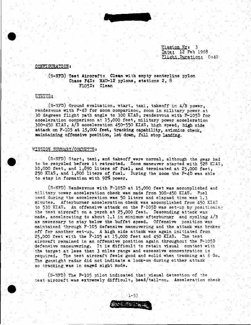
•
•
•
CONFIQURA TI ON 1
1::UM.ion Nra 3 Dat~t 12 Feb 1968 Fli glll_Dura ti ~U.! 0:40
(S-NFD) Teat !irorafta Clean with empty oenterline pylon Chase F4Da MAu-12 pylons, stations 2, 8
Fl05Da Clean
(S-NFD) Ground evaluation, start, taxi, takeoff in A/B power, rendezvous with F-4D for zoom comparison, zoom in military power at 30 degrees flight path angle to 300 KIAS, rendezvous with F-105D for acceleration comparison at 15,000 feet, military power acceleration 300-450 KIAS, A/B acceleration 45o-550 KIAS, high speed, high side
··attack on F-105 at 15,000 feet, tracking capability, avionics check, maintaining offensive position, let· down, .1'ull stop landing.
1~gQWJmU':'~I
(S-NFD) Start, taxi, and takeoff were normal, although the gear had to be recycled before it retracted. Zoom maneuver started with 528 KIAS, 10,000 feet, and 1,890 liters of fuel, and terminated at 25,000 feet, 250 KIAS, and 1,800 li tars of fuel. Dllring the zoom the F-4D was able to stay in formation with 9~ power.
(~-NFD) Rendezvous with F-105D at 15,000 feet was accomplished and military nower acceleration check was made from 300-450 KIAS. Fuel used during the acceleration was 50 liters and elapsed time was 1.3 minutes. Afterburner acceleration check was accomplished from 450 KIA.S to 530 KIA~. An offensive attack on the F·l05D was set-up by positionin:: the test aircraft on a perch at 25,000 feet. Descending attack was mad~, accele~ating to about 1.1 in minimum afterburner and cycling A/3 as necessary to stay below the buffet speed. Offensive position was maintained through F-105 defensive maneuvering and the attack was broken off for another set-up. A high side attack was again initiated from 25,000 feet with the F-105 at 15,000 feet and 450 KIAS. The test aircraft remained in an offensive position again throughout the ~105D defensive maneuvering. It is difficult to retain visual contact with the target at less than 3 miles range and excessive concentration is required. The test aircraft feels good and solid when tracking at 6 Gs. The gunsight radar did not indicate a look-on during either attack so tracking was in caged sight mode.
(S-NFD) The ~105 pilot indicated that visual detection of the test aircraft was extremely difficult, head/tail-on. Acceleration check
l-53

Man Nr 3 in military power indicated little performance difference in the two aircraft. Due to A/B ignition delay on the afterburner· aooeleration, the F-105 initially started to separate. After the test aircraft obtained afterburner light-off, the acceleration performance appeared equal to the F-105D. During defensive maneuvering, the F-105 pilot had a tendency to overestimate the range to the test aircraft because of its very small size. A 4·0 level turn by the F-105 into the attacker did not produce an overshoot and a level break turn in afterburner power only resulted in excessive airspeed bleed-off for the F-105.
(S-NFD) The second attack by the test aircraft was initiated at 25,000 feet. The F-105 accelerated to .9 IMN at 15,000 feet and started a descending hard ~urn as the attacker called missile launch, terminated A/B and continued a high G roll underneath. Visual contact was lost during this roll and effectiveness of the maneuver was compromised. The test aircraft remained in an offensive, tracking position throughout the F-105 defensive maneuvering. During the attack, the test aircraft attained 7 Gs while remaining in the offensive posture. The test aircraft produced a very noticeable afterburner puff at altitudes above 15,000 teet when engaging and disengaging the afterburner.
•
•
•

•
•
•
CONFIGURffiONa
Mission Nra 5 Datea 18 Feb 1968 Flight Durationa Os45
(S)Test Aircrafta Clean with empty centerline pylon F'-4D Participant 1 MAU-12 pylons, stations 2,8 F-4D Chases MAU-12 pylons, stations 2,8
EVENTS:
(S) Ground checks, start, taxi, af~erburner power takeoff, military power climb to 20,000 feet at • 9 nm, level defensive maneuvering against high speed, high side attack by F'-4D, defensive maneuvering and wings level afterburner power zoom, offensive maneuvering for photo analysis, simulated flameout approach to landing, full stop landing
lU,~SION SUMMARY /Q.QMMENTS 1
(S) Taxi and takeoff were normal although several recycles were necessary before the gear would retract. Military power climb to 20,000 feet at .9 IMN was made and rendezvous was .effected with F-4D for defensive combat maneuvering.
(s) The test aircraft stabilized at 20,000 feet, .9 IMN, for the first attack. The F·4D initiated the attack from 25,000 feet and a~celerated to 1.2 IM}l with an initial TCA of 30 degrees. 1lissile er:velope was achieved by the F ·4D and simulated missile launch was called. The test aircraft turned into the F-4 and continued attempting ~o negate the attack. The F-4D closed into gun envolope, tracked thA test aircraft with 6.8 G, and was not forced to overshoot.
(s) The second maneuver's initial conditions were established similar to the first. The F-4D attacker accelerated to 1.2 nm during the initial situation at 30 degrees TCA. Reversal was made as missile envelope was reached and TCA decreased to about 10 degrees. Tracking required 7 Gs and the test aircraft generated a hard turn into the attack and caused an oveshoot. As the F'-4 overshot high and outside the test aircraft, visual contact with the F'-4D was lost and the third maneuver was set-up.
(S) Initial conditions for the third maneuver were the same as previous attacks. At missile launch range, the test aircraft started a level 3 G turn into the attacker and increased to 5.5 Gs. The attacking F-4D was forced to overshoot and both aircraft execu~ed a wings-level zoom •
a;"f '.··~ ..
l-55

Men Nr 5 (S) Conditions for the fourth maneuver were established with the
test aircraft initiating an attack on the ~4. The ~4D defender was stabilized at 15,000 feet and Mach .9. The attack was started by the test aircraft at 25,000 feet and 450 KIAS from a high perch position. A simulated missile launch was called at 1.5 miles range and the ~4 executed a hard turn at 3 Gs increasing to 7 Gs. An overshoot resulted and the test aircraft was forced outside the turn and pulled high. The test aircraft attempted to pull back down and inside the ~4 to continue offensive maneuvering' however, the F-4D reversed as the overshoot occurred and set up a scissors type maneuver. Maneuvering was terminated before the engagement progressed to low speed scissors.
(U) The test aircraft returned for simulated forced landing pattern and full stop landing.
(s) By using afterburner modulation, speed brakes, and G load for airspeed control, the F-4D sucessfully maintained an offensive posture during the first attack. With similar initial conditions on the second offensive engagement, the ~4 did not reduce power during the attack and was forced to overshoot high and to the outside of the test aircraft. Poor rearward visibility from the test aircraft caused loss of visual contact with the attacker and subsequent maneuvering for an offensive position was not possible.
(s) As an overshoot was generated on the third engagement, the ~4 pilot called for a wings-level zoom to be executed. With about equal flight conditions at entry into the zoom maneuver, both aircraft performed a maximum performance zoom in afterburner power. It was determined that the ~4 attained 2,000 - 3,000 feet more altitude than the test aircraft and could have maintained an offensive posture.
(S) Defensive maneuvering by the F-4 during the last engagement caused the test aircraft to overshoot. A 7 G, nose high reversal by the F-4D permitted attainment of an offensive posture. Radar lock-on indications wer~ not obtained by the test aircraft during this attack.
l-56
•
•
•

•
•
•
C01JFI GTJii4TI O:r:J: 1
Uission !Ira 7 ~~ 19 Feb 1968 Flight Duration: 0:30
(S)~est Aircraft: Clean, with empty centerline pylon Participants&
F-4D Ur la MATT-12 pylons, stations 2 and 8, missile launcher AHD AD~-4D 'I'm.: F-4D :~r 2: ~.'ATJ-12 pylons, sta:ions 2 and 8, LAU-7/A missile launchers and 4/ AIM-9B missiles.
(s) Grou~d check~, start, taxi, afterburner power takeoff, mili~ary nower climb to 15,000 feet, offensive maneuvering with two F-4D aircraft at 15,000 feet, IR signature documentation, reversal charact~ri~tics, straight·in simulated flameout landing approach, full stop landing.
(s) Start, taxi and ground checks were n\lr;,al; however, i~. 1ras nece~c:;ary to rec7cle the gear handle before gear retraction occ;1rred. '2:'he first attack was head-on at co-altitude with the F-4D's at 16,000 feet, .9 nm. 'rhe F-4 formatif'ln W<MS spread, simulating two elements. As visual contact was obtained, the test aircraft initiated a level turn toward the F-4's and p~~led to about 7 Gs, attempting to achieve a rear hemisphere position on the !~r 2 F-4 who was low. Both F-4' s started turning toward the test aircraft, using maximum pow·er. ~Tr 2 F . executed a climbing turn and Ur 1 F-4 turned down (split plane ma:;euvering). As the test aircraft attempted to achieve a kill position on the ~·!r 2 F-4, lead F'-4 rolled high, executed a ";,-o-;ro" and closed to gun kill position while trackine the test aircraft. '::'~P lest aircraft was unable to track 1Tr 2 F'-4 at any time during the engagement.
(S) The second engagement was initiated \Vith the test aircraf"' in offensive posture and the F-4's in fighting wing formation, a~ 16,000 feet and • 9 T!.!N. During the high side attack, the test aircraft selected the wingman ('Jr 2 F'-4) and pressed the attack. F-4 lead called for a split and started a climbing turn as 1!r 2 F'-4D turned down in a high G, full power spiral. The attacker was able to track ini"!:iall;;t, but could not match the F-4's performance thr0ugh the spiral, and because of energ·r lost could not track. Lead F'-4 turned in behind the test aircraf:, clcsed to 1,000 feet while tracking, and achieved a kill.
(::;) ,he third engagement started \Vi th the test aircraf"':. ini tia :ir.f a hich side attack, once again with the two F'-4's a-t 16,000 feet, .9 ::::-:::, in element formation. The attacker closed from 4 o'clock to 4,000 feet
l-57
-- ---------------~-----------------

Man Nr 7 range as tae 11'·4 element maneuvered into a hard right turn. The attacker was tracking in a lead pursuit curve with 3.5 ·oa .as F-4 Nr 1 initiated a defensive split. As the split occurred with F-4 Nr 2 descending, the test aircraft changed his attack to F-4 Nr 1. As the range decreased to about 2,000 feet, F·4 Nr 1 performed a hith G roll underneath and caused the attacker to overshoot. Lead F-4 (Nr 1) then reversed and became offensive as the test aircraft was forced into the forward hemisphere.
(S) As the test aircraft returned for a simulated flameout approach, IR tone signatures were recorded by AI~4D and Ait~9B missiles. A.malfunction in the AI~4D prevented discernible tone shift at cooling. The A1~9B tone was good on the test aircraft and there was no appreciable tone difference in the test aircraft and the F-4D chase aircraft.
(C) A straight-in, simulated flameout pattern was performed by the test aircraft, followed by a full stop landing.
1-58
•
•
•

•
•
•
CO~TFIGTJRATIOU I
Mission lir 1 8 ~~ · 19 Feb 1968 Flight Duration: 0:35
(s) Test Aircrafta Clean with empty centerline pylon 2/F-105DI Clean
EVENTS1
(s) Ground evaluation, start, taxi, takeoff, military power climb to 10,000 feet, acceleration checks in military and afterburner power with F-105D defensive maneuvering at 16,000 feet, offensive maneuvering defensive vertical maneuvering, photo documentation, simulated flameout approach, go-arcund, full stop landing.
liTS~,IO~T 8t1MMARtLCm.MJH~§:
(S) The acceleration check was performed at 10,000 feet in military power from 400 to 500 KIAS. As the test aircraft reached 500 KIAS, the F-105D was indicating 494 knots and was abcut 300 feet behind. Speed brakes were extended to compare deceleration performance and it was immediately obvious that the ~105 was superior. Afterburner acceleration check was started at 400 knots and terminated about 500 KIAS. Again, the acceleration performance of the two aircraft was very close, with a slight margin in favor of the test aircraft. This check was performed with a fuel wieght of 5,500 pounds for the F-105, and 2100 liters (3723 lb) in the test aircraft.
(S) E~gagement numbe~ 1 for the mission was set-up with the test aircraft in a defensive posture at 16,000 feet and .9 nm. The element of F-105D's initiated a high speed attack from 6 o'clock. A simulated missle launch was called at 6,000 feet range and the test aircraft entered a 4 G turn. The attackers continued closing for a gun attack to 2,000 feet range. All aircraft were operating in afterburner power and the test aircraft increased the turn rate to 5 Ga. The attackers were forced into a slight overshoot and elected to disengage by performing an unloaded acceleration. The F-105's reversed, unloaded, and accelerated away as the test aircraft attempted a high G reversal. Visual contact with the attackers was lost and .their separation was successful.
(3) The second engagement was initiated with the test aircraft in an offensive mode. The two ~105D aircraft were in formation, simulatinb a strike force element, at 15,000 feet, 450 KCAS. The at~acker closed on the F-105 element from 5 o'clock with about a 100 knot closure ra:e. As the test aircraft closed to missile range, the F-105 1 s started a hard right turn and split, with the wingman descendin~ and the lead climbing. The attacker pressed for the low aircraft (number 2), who
1-59

f.: ..
Msn Nr 8 engaged afterburner and increased the G load to maximum. The attacker maintained a 6 o 1olook position on ~105 number 2, but could not track smoothly. The lead '-105, through split plane maneuvering, was able to effect a "yo-yo" and attain a lethal gun position on the test aircraft and maintained the offensive posture for an effective kill.
(s) The last engagement was performed with the test airoraft in defensive posture at 16,000 feet and .9 IMN. P-105 element was positioned directly astern at 6,000 feet range for a simulated missile launch. As this launch was called, the test aircraft entered a full power, 3.5 a, climbing spiral. The F-105 element could not match the turn-climb performance and would have dissipated energy to an unacceptable level. The engagement was terminated.
(S) Photo documentation was accomplished as the test aircraft positioned for a simulated flameout approach. The approach was performed at 250 XIAS, then 350 KIAS, as a steeper descent to a point 1.5 miles short of the landing runway was established. Flare was started at about 1,000 feet for the low approach.
(U) A go-around was executed, followed by a full stop landing.
(S) This mission demonstrated that the P-105, using a lag pursuit attaok, could press for a suooesstul kill if an initial offensive advantage existed. The ~105's oould separate successfully and could use the high G break turn to negate an attaok. P-105 level acceleration performance at 10,000 feet in military and afterburner power was comparable to the test airoraft.
1-60
•
•
•

•
•
•
CONFIGURATION a
Mission Nr I 9 Date1 20 Feb 1968 Flight ]urationa 0145
(s) Test Aircrafta Clean, with empty centerline pylon P-105Da AIM-9], outboard stations
EVENTSt
(s) Ground evaluation, taxi, mn~mwn afterburner, takeoff, military power climb to 15,000 feet, set-up head-on flight OODditions for air combat maneuvering with P-105D, high speed attack on P-105 during dive bomb run and attempt gun kill, attack F-105 at 15,000 feet from astern ~osition, record IR signature, ~erform simulated flameout approach to landing, go-around, and full stop landing.
MISSION SUMMARY/COMMENTSt
(s) The first engagement was initiated with the test aircraft and F-105 maintaining head-on track from long range (20 NM). ]oth aircraft were established at 15,000 feet, .9 IMN. As both aircraft passed line abreast with about .5 miles separation, each started a turn toward the other, attempting to secure an offensive kill position. The P-105 accelerated to 1.02 in afterburner on the initial turn-in. After 180 degrees of turn had been completed, the teet airc~aft and P-105 were still essentially in a head-on standoff. As the maneuvering progressed, the teet aircraft pilot momentarily lost eight of the P-105 and reacquired the chase F-4 aircraft mist~:enly, and oriented his ACM on the F-4 chase. As this occurred, the F-105 attained a kill position on the teet aircraft.
(S) The second engagement was started with the teet aircraft attacking the F-105 while it was on a simulated dive bomb attack. As the F-105 pulled out of the 45 degrees dive bomb run at 580 KIAS, the test aircraft acquired about 550 KIAS attempting to close to a lethal range. Hard "jinking" action by the P-105 allowed the teet aircraft to close to gun range and traak momentarily.
(S) The test aircraft was positioned astern the P-105 for a high speed attack at 15,000 feet. As "missile away" was called, the F-105 initiated a 3 G turn to defeat the missile. The teet aircraft continued closing to gun range and tracked the P-105 briefly. The test aircraft then rolled out of the tracking turn and attempted a level separation in afterburner power. The F-105 reversed his defensive turn and had the c~ability :o launch a missile at the separating aircraft •
l-61
' (

Man Nr 9 (s) IR signatures were documented by the Aiif:-9B equipped F-105.
Missile tone increases in pitch and intensity as the teet aircraft engages afterburner.
(U) A random simulated flameout pattern and low approach was accomplished by the test aircraft and a full stop, normal landing was made.
(s) High longitudinal stick forces reduce the test aircraft's maneuvering potential at airspeed over 500 knots. If the F-105 had elected to Reparate at an airspeed over 600 KIAS, it is felt that this maneuver would have been successful, because of the maneuvering and structural limit of the test aircraft. A straight-ahead acceleration without violent "jinking" action may be a more appropriate separation/ defensive maneuver.
1-62
•
•
•

•
•
•
CO~TFIGURATIO~J:
~:ission Nr: 13 Dater · 18 Feb 1968 Fiiiht DurationJ. o :40
(s) Test Aircraft: Clean with empty centerline pylon F4Dr tiAU-12 armament pylons, stations 2,8
EVENTS:
(S) Ground checks, taxi, takeoff, military power climb to 10,000 feet rendezvous wi~h F-4D, comparative military power acceleration from 300 to 450 KCAS, maximum power zoom comparison, unloaded maximum power acceleration performance comparison, turn performance comparison with F-4 at 35,000 feet and 20,000 feet, military power zoom comparison Dm.!with F'-4 at 20,000 feet, 400 ICIAS, Am.~ with defensive F'-4D at 10,000 feet, 400 KCAS, letdown, full stop landing •
.ru_sroN SUMMARYLcotnE:N'T~:
(s) Acceleration performance of the test aircraft compared with the ?-4D was investigated at 10,000 feet. Both aircraft stabilized line abreast at 300 KIAS and applied ~<11 military power while maintaining l9vel flieht. ~he F-4D reached 450 KCAS after 38 seconds elapsed time and the test aircraft required 51 seconds to accelerate to 450 KlAS.
(~) Zoom comparison was initiated at 15,000 feet, .8 ~~r, in afterburn~r ~ower with both aircraft line abreast. A standard pitch rate wa~ p~rformed to achieve a 30 degree flight path angle climb. A~ the zoor.~ wa!"! terminated b:.r the tes-:. aircraft at 28,000 feet, 270 KIA3, the ~·4 had a:tained 32,000 feet and indicated 300 KCAS.
(s) From 40,000 feet at 260 KIAS, both aircraft in line abreast position star.!;e'd a maximum power, descending acceleration. At 1.1 IMN, the F·4D accelerated ahead of the test aircraft and was 300 feet i'1 front at 1.2 n.?.r. A wind-up maximum performance turn at 35,000 feet was initiated by both aircraft, which resulted in the test aircraft's attaining about 5.60 and rolling out after 360 degrees of turn with 230 KIAS. The F'-4 attained 6 G's initially and rolled out after 360° of turn with 300 KCAS. ·
(s) '.Vhile descending to 20,000 feet at .9 nm' anot!ler wind-up maxi~1m performance turn was accomplished. The test aircraft reached 6 G's initially, which dissipated to 3 G1s as the airspeed bled off. The F'-4 attained 6.5 G's initially and bled off to 4 G's as the turn progressed. Both aircraft rolled out of the turn simultaneously and the F'-4 had 80 KCAS more than the test aircraft •
l-63

Men Nr 13
(s) A military power comparative zoom climb was performei starting at 10,000 feet, .9n~;. A ~tandard 2.5 G pitch rate to 30 degrees flight path angle was accomplished with both a~rcraft line a~reast. At simultaneous zoom termination, the test aircraft at 19,500 feet had 300 KIAS; the F-4D at 21,500 feet had 320 KCAS.
(S) ACl~ was initiated with the F·4D offensive. A high side pass at 1.1 was started by the F-4 at 25,000 fee~. The test aircraft was established at 20,000 feet, 400 KIAS. As the attack progressed to missile range, the defender rolled into a 6 G, afterburner power turn. By modulating speed brakes and afterburner, the F·4 attacker maintained a pursuit curve without being forced into an overshoot.
(s) The second engagement was performed \'fi th the F-4D in a defensive !JOSture at 10,000 feet, 400 KCAS. A high side attack was started b~; the test aircraft accelerating in afterburner 7-o about 500 KIA3. '!'he F-4 initiated a 3 G turn at missile launch, increased to 7 G's as the attacker decreased range. The test aircraft was forced to -:he outside of the turn and the F-4 rolled wings level and performed a vertical zoom. As the zoom ~aneuver was started, the test aircraft attempted to follow, but because of low airspeed, could not maintain a tracking position behind the F-4. The engagement was terminated.
(1T) The test aircraft returned to base, performed an idle letdown with speed brakes extended, normal full stop landing.
:-6L
•
•
•

••
•
•
CONFIGURATION:
~.:i §l§.ion Nr s 22 Dat~z 24 Feb 1968 Flight Duration! Or35
(s) Test Aircraft& Clean with centerline pylon 4/~4D
EVENTS:
(S) Ground checks, taxi, takeoff in mJ.nJ.murn afterburner power, climb to 23,000 feet while ~8 obtains IR documentation, establish track for head-on engagement at .9 I1nT, repeat set-up for similar engagement, attack four F-4's from rear hemisphere at 20,000 feet, maximum IAS, photo data, letdown to initial approach, full stop landing.
l·:IT 8 8 I Q!L~.1JMMAR y I COUMS!IT§.t
(S) The first engagement was set-up with the flight track established by the test aircraft at 23,000 feet, • 9 UniT. The flight of F·4's did not detect the test aircraft on radar during about 30 miles of head-on convergence. The test aircraft visually acquired the F-4's, converted to a rear hemisphere attack and completed a gun attack on F-4 number 2, who had performed a hard turn at 5 G. Al'ter tracking for several seconds, the test aircraft switched his attack to F-4 number 1, who had increased the hard turn to about 6.5 G•s. Tracking of F-4 number 1 was accomplished by the test aircraft at about 6.8 G's maximum. Airframe buffeting was experienced by the test aircraft at 15,000 feet, 520 KIASJ however, power reduction eliminated the buffet. Turn reversals were accomplaihed effectively at 170 KIAS by the test aircraft. As F-4 element (numbers 3 and 4) obtained a rear hemisphere position on the teat aircraft, this engagement was terminated.
(s) Similar initial conditions were set-up on enga59ment 2 and the ~4's acquired the test aircraft simultaneously on radar and visually at 2-3 miles. ~4 numbers 1 and 2 maneuvered vertically to the rear hemisphere of the test aircraft who had not acquired the ~4's visually. ~his engagement was terminated as the ~4's closed to lethal gun range because of the inability of the teat aircraft to visually acquire the attackers.
(S) Initial conditions for the third engagement were established by the F-4's in pod (ECM) formation at 20,000 feet, 450 KIAS. The teat aircraft, executing a simulated GCI high-sp'3ed a"ctack from the rear of the ~4 flight~ closed to gun range on F-4 ~umber 4. D~i~g this closure, the test ~ircraft experienced light b~ffeting at 18,000 feet, 500 KIAS, and obtained vis~al acquisitio~ o~ :he F-4 1 s at about 8 miles. F-4'e performed a 7G desoe:1ding t'..:.rn/break and the
::.-65

Man Nr 22 aircraft maneuvered into the vertical, rolled off, and back down on F-4 number 4 for a gun kill. F-4'e number 1 and 2 were able to effect a sandwich maneuver and become offensive as the engagement terminated.
(S) Radar and visual search natterns proved to be inadequate during this mission and further analysis is required. Vertical maneuvering by the F·4'e with superior zoom, and sustained G made it possible to gain an advantage on thetest aircraft. Once the teet aircraft is in a lethal rear hemisphere position, a maximum performance break appears to be necessary to negate the immediate attack. Support of second element or wingman is necessary to insure survival against re-attacks, since a low energy state exists after the maximum--performance, last-ditch, break maneuver.
(C) Limited visibility rearward from the test aircraft is a severe restriction that should be capitalized upon.
:-66
•
•
•

•
•
•
CONFIGURATION:
Mission Nra 25 Date: 25 Feb 1968 Flight Purationa 0:35
(S) Test Aircraft: Clean with-empty centerline pylon F'-lOODa Clean
EVENTS:
(s) Ground checks, taxi, takeoff in m~n~mum afterburner, military power climb to 15,000 feet, head-on engagement with F'-100, .9IMN, rear hemisphere attack on the F-100 at 15,000 feet, line abreast position for Am~, letdown, full stop landing.
~§.ll.Q..'J STJMMAR y L CONJ.!m_!lr§.:
(s) After military climb to 15,000 feet, conditions for the first engagement were established at .9IMN. A head-on flight path was set-up and after visual acquisition at 3 miles, each aircraft entered a maximum performance turn. After 180 degrees, the test aircraft appeared to have turned about 20 degrees more than the F-100. At the end of 360 degrees of F-100 turning, the test aircraft had gained a significant advantage. Both aircraft were operating in afterburner power and after the ma.ximum·.~performance turn had lost considerable energy. A slow speed, turning situation was apparent and this engagement was terminated. The test aircraft assumed the offensive mode for the second engagement and initiated a high speed attack from the F'-lOO's rear hemisphere. Range was decreased through missile range and into gun range as tracking was accomplished. The F-100 performed a hard turn to negate the missile and maximum performance break to thwart the gun attack. The test aircraft was forced to overshoot and the F'-100 reversed as it ·occurred. A "yrryo" was executed by the test aircraft into the vertical and the engagement was terminated during this temporary stalemate.
(S) Initial conditions for the third engagement were set-up with the F-100 in an offensive posture and test aircraft at 15,000 feet, 450 KIAS. An attack was initiated by the F'-100 from 6 o'clock with about 75 knots~elosure rate. Although the test aircraft performed a hard turn in military power at missile launch, the F'-100 continued to maintain a stead;,• closure while tracking. A "yo-yo" into the vertical was executed by the F'-100 to prevent an overshoot, which was followed by a roll-off and further offensive positioning. The test aircraft lost visual contact with the F-100 at simulated missile launch.
(S) Th~ fourth engagement was initiated with the aircraft in line abreast position at 1.5 miles range. Vertical maneuvering was si~~ltaneously initiated as each aircraft attempted to gain an·offensive
2.-67

Men Nr 25 ~oeture as the test aircraft executed an unloaded acceleration and vertical zoom.
(s) The F-100, with an initial position advantage (rear hemisphere) is capable of completing a successful attack on the test aircraft. However, it is not capable of out-performing the test aircraft in a sustained maneuvering engagement. An overshoot by the test aircraft can be obtained by the F·lOO's performing a maximum performance break turn. Rear visibility restriction in the test aircraft is a significant tactical disadvantage that should be exploited.
" I~ .L-Cc
•
•
•

~--------------------~--------------------------------------------
•
•
•
QQliuqtffi~TI.Q~t
1.1ission Nrt 27 D~: 26 Feb 1968 Flight Dura~ion: 0:40
(s) Test Aircraft: Clean with emp~y centerline pylon F-lllAa Clean
EVE~r.'S:
(s) Ground checks, taxi, minimum afterburner takeoff, mili~ary power climb to 15,000 feet, rendezvous with ~111 and initiate a high side a-+;~ack, attack ~111 from abeam position at 15,000 feet, defensive maneuvering with F-111 at 15,000 feet and attempt to become offensive, letdown, full stop landing.
vrssr mr Sl:J!.:!.".A.'ZY /cm~!ENTS a
(S) Rendezvous was accomplished \Vi th the F-111 at 15,000 feet and the test aircraft established conditions for a high side attack. The test aircraft started the attack from the 7 o'clock position of the F-111 and accelerated to 525 KIAS. Simulated missile launch was called at 1 to 1-1/2 miles and the F-111 started a moderate, descendine left turn at 3-1/2 G's. Afterburner was engaged by the F-111 and after abnut 270 de£Tees of turn, the wings were swept to attempt high !.Tach separation. iJisual contact with the attacker was lost. The test aircraft maintained a gun tracking position on the F-111 for about 30 seconds, and the F-lll 1s separation maneuver was not effective until reaching an airspeed above 560 KCAS. At this point, it was apparent that the test aircraft could no longer maintain position, du~ to the airframe buffet at high indicated airspeed.
(::-;) For ~he second engagement, the F-111 maintain9d 450 K:'A3 at 15,000 feet and the te~t aircraft set-up an attack from the 3 o'clock nosition. The attacker S3lected afterburner power and accelerated to 525 KIAS during the initial pursuit. Since the attack was oriented from the right side of the F-111, the right seat pilot commanded the airplane. He started a hard right turn and called for 16 degrees wing sweep. Due to cockpit confusion, the F-111 left seat pilot aircraft commander interpreted the call as 60 degress and selected ~he full aft position on the wings. The test aircraft overshot due to the 70 degrees '::CA and pulled into ~he vertical for a high "yo-yo" maneuver. The F'-111 reversed the ~urn as the overshoot occurred in an a~tempt ~o scissors the test aircraft. Cloud conditions prevented further maneuvering during this engagement.
(S) Test aircraft flight conditions for the ~hird engagement were established at 15,000 feet, 450 KIAS. The F-111 initiated the attack
1-69

Men lrr 27 4 o'clock position, co-altitude, and accelerated to 1.1. n'::J prior to reaching missile range. A climbing, hard right turn in afterburner was performed by the test aircraft and the P-111 closed to gun range, selected 26 degrees wing sweep and momentarily tracked the test aircraft at maximum gun range (3,000 feet). As the zoom maneuver progressed, the test aircraft achieved separation and the engagement was terminated. 1!.inimum fuel was reached and the test aircraft returned to base for full stop landing.
(S) ~o generate an over shoot, the F-111 must initiate a maxi~~ performance turn while the attacker is out of gun range and immediately effect separation by an unloaded acceleration at full power. At a low enere:r state in a maneuvering engagement with the test aircraft,, the F·lll is extremely vulnerable. Poor rearward visibility and side-by-side seating further degrade the F-lll's air-to-air capability. If initially in an offensive rear hemisphere position, the F-111 can effect a missile a~- tack and probably convert to a gun attack. As the test aircraft maneuvers vertically, the F-111 should attempt to separate.
l-70
•
•
•

•
•
•
CONFI GTffiATI OlT 1
!.~ission Nr 1 30 ~ate: 27 Feb 1968 Flight Puration1 0130
(s) ~est Aircraft: Clean with empty centerline pylon. F-4E: Clean
EVENTS:
(S) Ground checks, taxi, takeoff in m~n~mum afterburner power, mili tar;r power climb to 30 ,coo feet' establish track at 1. 2 nrn for head·on ACt! with F-4E, repeat first engagemen·t at 15,000 feet, 550 KIAS, scissors comparison at 20,000 feet, letdown, full stop landing.
WISSI<)J!..§.ID~.~Y/C0!.!1.1ENTS:
(S) The first engagement was initiated with the F·4E and test aircraft on opposing tracks at 30,000 feet, 1.2 IMN. Visual detection for both aircraft occurred at about 4 miles range and simultaneous turns were started toward each other. Initial lateral separation was two miles and as the aircraft turned towards each other, the test aircraft crossed the F-4 track at 110 degrees. Continued hard maneuvering through a series of zooms, turns, and "yo-yo" resulted in the F'-4E 1s becoming defensive and the :est aircraft in a position for a gun kill.
(S) Initial oonditons for the second engagement were established with each aircraft at 15,000 feet, 550 KIAS, on opposing flight tracks. Visual detection was not obtained and each aircraft performed a 18Q-degree turn-around. During the turn, visual acquisition by the P-4E was established and the F-4 "yo-yoed~ high, turning toward the 6 o'clock position of the· test aircraft. The test aircraft did not acquire the attacking F-4E d~e to the limited rearward visibility, and the engagement was terminated with the F-4E in gun tracking range and position.
(S) A scissors comparison was accomplished on the third engagement and both aircraft were initially established line abreast, co-speed, 20,000 feet. On the first turn in, the F-4E established a higher climb angle than the test aircraft and gained an altitude advantage as TCA was 90 degrees. Two more reversals were executed and the F-4E, maintaining an·offensive postcore, attempted to track the test aircraft for a gun kill. Energy dissination during the tracking attempt by the F·4, and a nose-high rolling maneuver by the test aircraft resulted in the test aircraft's achieving an offensive position in the rear hemisphere of the F-4E. The F-4 fuel was 2,000 pounds, significantl7 below tha~ required in a normal corebat situation. Flaps were not used, although afterburner was used intermittently. "Bingo" fuel was called and all aircraft returned to base •
l-71

Men Nr 30
(s) The test aircraft demonstrated superior performance in the high altitude engagement. It would have been to the F-4E's advantage to force the flight ~o low altitude. Rear visibility limitation of the teet aircraft again was apparent as visual detection of the F-4 attacker in the rear hemisphere is difficult. A slow speed scissors with the test aircraft should be avoided.
1-72
•
•
•

•
•
•
CONFIGURATIOn:
Mission Nr: 37 Date: 29 Feb 1968 Flight Duration: 0:35
(S) Test Aircraft: Clean with empty centerline pylon F4Es Clean
· EVENTSa
(S) Ground checks, taxi, takeoff in m~n~mum afterburner power, military power climb to 20,000 feet for head-on ACM with P-4B, ACM at 15 ,ooo feet with F-4E on head-on set-up, defensive maneuvering with F-4E attacking from 4 o'clock at 15,000 feet, letdown, full stop landing.
li!ISSION SUM!.'!ARY /COMMENTS:
(s) An opposing track with the ~4E was established at 20,000 feet, 1.2 I'f.N· Visual detection was obtained (no radar) as both aircraft passed abeam at two miles range. Each aircraft maneuvered into the vertical and turned in towards each other. The F-4E achieved about 30° flight path angle, then turned down inside the test aircraft, which pulled up to about 500. As the test aircraft topped the zoom maneuver at a higher altitude, the F-4 continued turning toward the adversary and pulled up again into the vertical as the test aircraft unloaded and turned down into the F-4. Track c~ossing angle was 180°. Two more zooms in the vertical were performed by the test aircraft and each time, the F-4E maneuvered to achieve 180° of TCA. The engagement was terminated with neither aircraft gaining an advantage.
(S) Head-on conditions were established at 15,000 feet, .95 nm, for the second·engagement. Maneuvering started as each aircraft passed line abreast at 1 mile. The P-4E and test aircraft pulled into the vertical and achieved about a 70° flight path angle. Floating over the top of this zoom at 100 KIAS, the test aircraft lost visual contact with the F'-4 and turned in a direction which allowed the P-4 to roll into the rear hemisphere and assume a kill posture. The engagement was terminated.
(S) The P-4E initiated a high side attack on the test aircraft at 15,000 feet, 450 KIAS, for the third engagement. The F-4 accelerated in afterburner power to 1.2 IMN and at 3-4 miles range with 70° TCA, at~empted a barrel roll attaok which turned into a high "yo-yo" and a rolloff. A turn into the attacker was initiated by the test aircraft and the F-4 lost visual contact during the high rolloff. An unloaded acceleration was accomplished by the F-4 to separate. As 1.2 nm was obtained, the F'-4E pulled up for a vertical zoom at 80° flight ~ath angie •
l-73

Msn Nr 3"7 The test aircraft in the rear hemi~phere outside of g~n range could not match the F-4's zoom performance. A slow reversal by the F-4 at the apex of the zoom set-up a rolloff ~o the blind cone of the test aircraft. The engagement was terminated with the F-43 in a lethal missile envelope. "Bingo" fuel was called and each aircraft returned to base fer landing.
(s) Vertical maneuvering by the F-4 must approach 90° to be effective. Determined maneuvering toward the test aircraft's blind cone instead of pressing for lead or pure pursuit appears to be advantageous and should be investigated further.
1-74
•
•
•

•
•
•
CONFIGURATION a
Mission Nr: 39 Date: 1 March 1968 Flight Duratio1.: 0:35
(S) Test Aircrafta Clean with empty centerline pylon F-4Ea MAU-12 armament pylons, stations 2 and 8, 2/A~9B missiles
EVENTS a
(s) Ground cheeks, taxi, takeoff in m~n~mum afterburner, military power climb to 20,000 feet, defensive combat maneuvering with F'-4E initiating high side attack at 1.2 IMN, head-on engagement at 15,000 feet, 450 KIAS, defensive maneuvering at 15,000 feet, 450 KIAS, repeat previous engagement, letdown, land.
l'J:SSION SUMMARY/COMMENTS 1
(s) For the first engagement, the F-4E with two AI1~9B missiles (inert) initiated a high side attack at 20,000 feet, 1.2 IMN. The test aircraft mQintained 450 KIAS until called clear to maneuver as the F'-4E reached missile range. At 3 miles range, the test aircraft initiated a turn toward the attacking F'-4. The F'-4 performed a high, vertical barrel roll inside the test aircraft and oriented the ACM toward the blind cone of the test aircraft. The F'-4 maintained an offensive position throughout the engagement and was able to simulate a missile and gun kill.
(S) The second engagement was a he~d-on, co-altitude set-up 11:t 15,000 feet, 450 IIAS. 1~neuvering was started as each aircraft passed line abreast. The test aircraft initiated a climbing turn and the F-4 performed a descending turn. A head-on missile launch was possible by the F-4 after 180° of turn in two instances. The engagement was terminated after the teet aircraft lost visual contact with the F-4E.
(3) Initial conditions for the third engagement were established at 15,000 feet, 450 KIAS, with the P-4E on a high p~rch for an attack. A dGscending turn toward the test aircraft was accom?lished in maximum ~ower, accelerating to 1.2 I~.:r. The attack was pressed to the rear blind area of the test aircraft in a lag nursuit technique. The test aircraft turned into the F-4 attacker and the P-4 executed a barrel-t:~e maneuver, remaJ.nJ.ng on the inside of the turn generated by the test aircraft. The F-4 was successful in closing to missile range and subsequently to gur. range for a tracking, simulated gun kill.
(s) The F-4E was again in the offensive mode for-the fourth engasement and the test aircraft was established at 15,000 feet, 450 KIAS. The F-4E accelerated to 1. 2 IMN and rolled tcmard the target, establishing a 600 TCA. The test aircraft was cleared to maneuver and
l-75

Msn Nr 39 performed a hard level turn into the attacker. To prevent an overshoot, the F-4 pulled into ~he vertical and executed a barrel roll ~o the outside, attempting to enter the test aircraft's blind area. Two re~~rsal~ occurred and during each, the F-4 directed the maneuvering toward the test aircraft's rear blind cone. An offensive position was maintained by the F-4 and a gun kill could have been achieved.
(U) 11l3ingo" fuel was called, and all aircraft returned to base.
(S) The bar~el roll attaok appears to be successful if executed toward the inside of the test aircraft. Lag pursuit, or orienting the maneuvering t:c:mard the test aircraft 1 s rear blind cone, produced desirable results.
l-76
•
•
•

•
•
•
CONFIGURATIOns
Mission Nrs 40 Dates 1 Mar 1968 Flight Durations Os35
(S) Test Aircrafts Clean with empty centerline pylon F-4E 1 ~.!.AU-12 armament pylons, s"ta tions 2,8 and 4/.<i:L,t-9B missiles
(s) Ground checks, taxi, minimum afterburn~r takeoff, military power climb to 10,000 feet, rendezvous with F-43 for zoom comparison, defensive maneuvering with F·4E at 20,000 feet, repeat at 15,000 feet, 450 KIAS, head-on engagement and ACU at 15,000 feet, letdoi7n, landing.
b1,SSIOU SLP..,::ARY /CO?.rr.t::UTS:
(S) Comparative zoom performance was evaluated starting at 10,000 feet, .9 I!=:, using full afterburner power. Both aircraft were positioned line abreast and established an equal pitch rate to achieve 40° flight path angle. Tne test aircraft initiated zoom termination at 250 KIAS. At the termination call, the ~4 had 2,000 feet higher altitude and 280 KIAS.
(S) Ini:ial conditions for the first engagement were established with the ~4 offensive and the test aircraft defensive at 20,000 feet, 450 KIAS. An attack was started with the ~4 accelerating to 1.25 Tin~ and rolling out toward the target with 50° TCA. u~neuvering by the test aircraft was started as the attacker entered the rear blind cone. A high G pull into the vertical, turning toward the direction of the attacker, was performed by the test aircraft. The ~4E was forced to overshoot and continued turning toward the test aircraft's rear hemisphere. A TCA of 100° resulted as the test aircraft turned dawn and into the attacker. A reversal and continued maneuvering by the F'-4 toward ~be target's blind cone resulted in the ~4 1 s maintaining a rear hemisphere position; however, a missile or gun attack was not possible because of the excessive TCA. The ACI~ was terminated.
(S) Conditions for the second engagement were aircraft at 15,000 feet, 450 KIAS, defensive, ~4E initiating a lag pursuit attack from 8 o'clock. The F-4 oriented the attack toward a point 3,000-4,000 feet behind the teet aircraft as a bard defensive turn was performed into the attack. The F-4 executed a pull-up into the vertical and a barrel roll to the outside of the target's turn. As the test aircraft pulled up vertical:y and turned toward the attacker, visual contact was lost with the Y-4. Visual re-acqt:.isition was obtained on the
l-77

Men Nr 40 F-4 ohaee aircraft instead of the F-4E attacker and the engagement was terminated.
(S) Head-on conditione were established for the third engagement at 15,000 feet, 450 KIAS. Radar oontaot was obtained by the F-4E at a range of 7 miles and visual acquisition was obtained at 3 miles. Maneuvering started as the test aircraft passed abeam eaoh other and the test aircraft pulled up to about 80° flight path angle, turning toward the ~4E, and then descending. After 180° of turn by the test aircraft, the ~4 had progressed through only 150° and the test aircraft gained a slight advantage. Energy in the 6•5 turn resulted in airspeed bleed-off to '310 KIAS for the test aircraft. The ~4, with 450 KCAS, pulled vertical into a zoom maneuver. Unable to oatoh the zoom, the test aircraft was forced to recover at a lower altitude than the F-4. A roll-off by the ~4 resulted in an offensive rear hemisphere position with 30° TCA at 1.5 miles.
(Ti) "Bingo" fuel was reached and all aircraft returned to base.
(S) The barrel roll attack produced desirable results and the lag pursuit technique appears valid. Zoom performance of the F-4E and olean teet aircraft demonstrated superior ~4 capability.
l-78
•
•
•

•
•
•
CONFIGURATION a
Mission Nr; 42 Date: 2 Mar 1968 Flight nurationa 0:35
(S) Test Aircraft: Clean with empty centerline pylon F'-4D: MAti-12 armament pylons, stations 2 and 8, with 4/LAti-7 missile launchers, S~l6 gun pod station 5.
EVENTS:
(S) Ground checks, taxi, mlnlmum afterburner takeoff, military power climb to 10,000 feet, rendezvous with F-4], zoom comparison, head-on AaM with F'-4 at 15,000 feet, offensive maneuvering with F'-4 at 15,000 feet, letdown, recovery.
MISSION STTMM4RY/CO'Ml@NTS 1
(S) A normal takeoff and climb to 10,000 feet was accomplished and rendezvous with the F'-4D was made. The zoom comparison was initiated at 10,000 feet, .9 IMN, both aircraft line abreast in afterburner power. A pull-up to 400 flight path angle was accomplished and with full power the relative position remained the same throughout the zoom •
(S) Engagement number 1 was set up with each aircraft in an opposing flight path at 15,000 feet, 450 KIAS. Maneuvering was started as the aircraft passed abeam at 1.5 miles. Each aircraft performed a descending turn in maximum power which resulted in the F'-4's gaining about 20° after 180° of turn. The test aircraft experienced airframe buffeting in the transonic regime, was forced to· reduce power Slightly, and after 360° of turn, the F'-4 maintained a slight advantage. The engagement was terminated.
(s) Engagement number 2 conditions were established with the F'-4 defensive at 15,000 feet, 450 KCAS, and the test aircraft initiating an attack at 1.05 IMN with 30° TCA. Simulated missile launch was called at 2 miles range and the F'-4 performed a climbing turn in afterburner power. The test aircraft closed to about 1/2 miles and tracked the F'-4 during the climbing turn. G load was increased to the maximum by the F'-4 at a 200 KCAS apex and the test aircraft overshot, to a position higher than the F-4. As the overshoot occurred, the F'-4 unloaded and accelerated momentarily, then pulled into a climbing turn toward the attacker, generating a 90° TCA. Continued maneuvering toward the test aircraft blind cone resulted in the F-4 attaining an offensive position in the rear hemisphere of the test aircraft. Missile/gun kill was not obtained as the engagement termnated.
(U) ''Bingo" fuel was rea~:-.9d b:.· tte test a.i:-cra.i't and reco\rery was effected •

!.:sn :rr 42
(s) Airspeed bleed-off by the ~4 to a low energy level on the first engagement was due to pilot misjudgment and the situation deteriorated to defensive. F-4 airspeed during ACM should not fall below 450 KCAS. Vertical maneuvering by the F-4 followed by roll-offs to the blind cone of the test aircraft proved to be very effective.
l-80
•
•
•

•
•
•
CONFIGURATION a
Miasion Nra 43 Dates 2 Mar 1968 Fi'i'i'ht Duration a 0 a40
(S) Teat Aircraft - Clean, with empty centerline pylon. 2/F-4E MAu-12 armament pylons, stations 2 and 8; 4/AIM-9B missiles.
EVENTS a
(s) Ground oheoka, taxi, takeoff in minimum afterburner, military power climb to 15,000 ft, converging track for enga~ement with F-4's at 450 kt, head-on set-up at 25,000 ft, .9 IMN, offensive posture for high aide attack on F-4's, letdown, landing.
MISSION SUMMARY/COMMENTSa
(U) Normal takeoff in minimum afterburner and military power climb to 15,000 tt was accomplished.
(s) Initial conditions for the first head-on engagement were established at 15,000 tt, 450 KCAS. No radar contact was obtained by the F-4's throughout the 40 mile converging track. Visual contact was not established and a 180° level turn was executed by the F-4's and the test aircraft. During this turn-around, the test aircraft sighted the F-4's and initiated an attack, closed to missile range on F-4 Nr. 2, overshot and switched the attack to F-4 Nr. 1. The F-4's were unable to visually acquire the teet aircraft until missile launch was called. F-4 lead then called for a hard turn reversal as the test aircraft overshot F-4 Nr. 2. After a series of vertical maneuvers, the test aircraft remained in an offensive posture and the engagement was terminated.
(s) A converging flight track was set up for the second engagement with the test aircraft at 25,000 ft, .9 IMN, and the two F-4E's at 15,000 and 20,000 simulating two elements in fluid four formation. F-4 Nr. 1 achieved a ~adar lock on the test aircraft at 15 miles and turned toward the target. A climbing attack into the test aircraft was performed by both F-4's and after several cycles of vertical "yoyo's", both F-4E aircraft were in the rear hemisphere of the test aircraft. Nr. 1 F-4 obtained an auto radar acquisition at 3,500 ft and closed to gun range.
(s) The third engagement was initiated at 15,000 ft with the test aircraft in the offensive and initiating the attack from an abeam position of the F-4 element. At 3 miles range, TCA of 6oo, the F-4's turned into the attacker. A defensive split was performed by the F-4's as the attacker closed to 3-4,000 ft range. F-4 Nr. 2 started a high G descending spiral and F-4 Nr. 1 pulled into a climb while waiting for the attacker to become committed to one target. Test aircraft elected to
1-81

Men Nr. 43 pu:.·sue the descending F-4 Nr. 2 and F-~ !r. 1 reversed down and effected. a aandwioh ~th the attacker. After 360~ of turn, the test aircraft and. F-4 Nr. 2 maintained a 180° TCA and F-4 Nr. 1 was able to sandwich and achieve a missile and gun kill position o~ the test aircraft.
(C) ":Bingo" fuel level was called by the test airoraft and it returned. to base for a normal landing.
(s) Radar detection was successful in the second engagement as the test aircraft was 5000 ft higher than the F-4's providing a look-up aspect. The defensive split was successful as the subsequent sandwich achieved a kill. During the high Q defensive spiral by F-4 Nr. 2 in the split, the test aircraft was unable to achieve a traoking solution. The auto radar acquisition was used with success; however, to be more useful, the effective range capability of this mode should be expanded to 5 miles.
l-82
•
•
•

•
•
•
CONFIGURATIONs
Mission Nrt 44 Dates 3 Mar 1968 Fi:Lght Durations Os50
(S) Test Aircraft - Clean, with empty centerline pylon. 4/F-4D-M10.12 armament pylons, stations 2 and 8J 4/AIM-9B mia*ilea.
EVENTSt
(S) Ground checks, taxi, minimum afterburner takeoff, military power climb to 25,000 ft for head-on set-up with F-4's, repeat head-on setup at 20,000 ft and ACM, high side attack on F-4's and AOM, letdown, landing.
MISSION SUMMABY/COMMENTSt
(s) After a normal takeoff and cl:r..Qto 25,000 ft, the teat aircraft set-up an opposing flight track with the F-4 1s. Lead F-4 element was established at 15,000 ft and F-4's Nr. 3 and 4 were positioned in fluid four formation at 18,000 ft, .9 IMN. During the 30-mile convergence, radar contact was not obtained by the F-4's (3 radar sets were operable).
(S) All aircraft reversed their flight path and another converging situation was established. The test aircraft descended to 20,000 ft. Radar contact was established at 12 miles by F-4 Nr. 3. F-4 Nr. 1 then acquired radar lock-on at 9 miles, as Nr. 3 initiated an acceleration for visual identification. F-4 lead performed a slight "jink" turn for additional separation, and turned toward the target as the ID was accomplished by F-4 Nr. 3. Loss of radar contact by F-4 Nr. 1 prevented a missile attack, and a close-in visual engagement developed. The test aircraft attempted to achieve an offensive position on the high element (F-4's Nr. 1 and 2); however, when it became app~ent that it was going~ require maneuvering into the vertical to a very low airspeed, the test aircraft attempted to disengage by an unloaded acceleration to maximum airspeed. The engagement was terminated.
(s) The next engagement was initiated by the test aircraft at 25,000 ft, attacking the flight of F-4's at 15,000 ft in fluid four formation. Rolling in from 8 o'clock to the F-4's, the test aircraft descended, orienting the attack on the high F-4 element (Nr. 3 and 4). Afterburner was engaged by the F-4' s as they performed a hard turn toward the attacker. An overshoot caused by the test aircraft being unable to match the F-4's turn rate occurred, and the F-4's reversed appropriately. The test aircraft then pulled up into a vertical zoom attempting to position on F-4' s Nr. 3 and 4•. This zoom resulted in the teet aircraft dissipating airspeed, and at a very low energy level, maneuvering ability was marginal. F-4's Nr. 3 and 4 were able to achieve an offensive position during the roll-off. The engagement was terminated with all four of the F-4D's in the rear hemisphere of the test aircraft •
l-83

Man Wr 44
(s) The search pattern used on this particular engagement was briefad &sl Wr. 1 and Wr. 3 radar operator search from slightly below the horizon to above the hori~on in map B mode. Nr. 2 and Nr. 4 radar operators in r&d&r mode were to overlap their search are&sJ however, their primary responsibility was visual soan. The visual coverage was to be standard as published in current tactical manuals. The visual coverage proved successful on the second engagement. Visual contact was acquired at the initiation of the attack and was never lost throughout the engagement. The ~4 elements did not maneuver in the same relative plane after the ACM was started. One element climbed and one element descended and through a aeries of high speed or anergy-maintaining turns (at least 450 KIAS), the entire flight of four was able to position to the rear hemisphere of the test aircraft and obtained missile shots and gun tracking solutions. During the engagement the opportunity developed for the ~4's to dive toward the blind area of tbe test aircraft. This resulted in offensive positioning by the F-4's.
All aircraft returned to base for recovery.
l-84
•
•
•

•
•
•
I
COHFTGURATION;
llission Nr; 45 Date; 3 Mar 1968 Flight ~ation; 0:35
(S) Test Ail"craft- Clean, with empty centerline pylon. 4/~4D 1 s- l~U-12 armament pylons, stations 2 and 8; 4/AIM-9B missiles.
(S) Ground checks, taxi, takeoff in m1nunum afterburner pov1er, mili tar:v 'Dower climb to 25 ,000 ft, bead-on ACM with F-4 1 s, abeam attack and ACM at 15.000 ft, reneat, letdown, full stop landing.
MISSION SUMMARY/COMME~S:
(S) The test aircraft establish~d an opnosing flight track with the 4/F-4 1s at 25,000 ft, .9 Jl~T. Fluid four formation was maintained by the F-4's at 15,000 and 18,000 ft, 450 KCAS. F-4 Nr 4 obtained radar lock-on with the test aircraft at 21 miles range. F-4 nr. 1 looked on the target at 18 miles and initiated an acceleration for visual identification. Positive identification was madP- at 3 mil~s range by F-4 Nr. 1 and the element was cleared for the attack. Minimum range prevented F-4 1 s Nr. 3 and 4 from missile launch ann Nr. 3 started to maneuver for a gun kill. F-4 leader and wingman, after the visual identification, maneuver~d directly into the vertical (Immelmann) and achieved a 6-mile trail position on the test aircraft. The test aircraft turned into F-4 1s Nr. 3 and 4 and a descending Lufbery dP.veloped for two 3600 turns, followed by a vertical "yo-yo". During the "yo-yo", P'-4 !rr. 3 closed to a gun tracking Position by performing a rnll-off and the engagemAnt was terminated.
(~) The tP.st aircraft initiated an attack from 3 o'clock to the four F'-4 1s on the second engagement. Flight conditions for the F-4 1 s were 15,000 ft, 450 KCAS. The attack was oriented toward the high element, F-4 1s Nr. 3 and 4, and a turn was started toward the attacker. Afterburner was selected by the lead F-4 and win~an as the null-up into a climbing turn was performed. A hard turn executed bv the Nr. 3 and 4 did not negate the attack, and the test aircraft closed for a missile launch. During the turning maneuver lead F'-4 and wingman closed to a gun range and tracked the test aircraft for an 8-second period. This engagement was terminated.
(S) For the last engagement, the test aircraft initiated an attack on the F-4's in fluid four for~tion at 15-18,000 feet, 450 KCAS. The attacker crossed over the lead F-4 element. to close on the high, trailin,g F'-4 1 s Nr. 3 and 4. Lead element turned toward the test
1-85

Men Nr 45
aircraft and achieved a rear hemisphere position, but could not obtain a missile or gun kill. Nr 3 and 4 F-4's did not visually acquire the attacker, but performed a defensive hard descending turn at the direction of F-4 lead. The test aircraft followed the descending F-4 1 s briefly and achieved a gun-tracking position, but due to excessive airspeed dissipation in the high G turn, was foroed to overshoot. ACM was terminated. A letdown and normal full stop landing was then accomplished.
(S) The technique of maintaining 450 KCAS minimum in a descending defensive break in full afterburner, then maneuvering in the vertical after the test aircraft has lost energy and maneuvering potential, appears to be valid. r.ru.tual support with coordinated element maneuvering proved to be a decisive factor.
1-86
•
•
•

•
•
•
CONFIGURATTON:
Mission Nr: 46 Date: 3 Mar 1968 Flight Duration: 0:45
(S) Test Aircraft- Clean, with emnty centerlinA nylon. 2/~4D's- l!AU-12 armamAnt nylons, stations 2 and 8; 4/AIM-9B missiles.
EVENTS a
(S) Ground checks, taxi, takeoff in m~n~mum afterburner, military power climb to 25,000 ft. for visual identification and attack on ~4 element, repeat, letdown, normal landing.
MISSION SJJMMARY/COMMEN'flSa
(S) Normal takeoff and climb to 25,000 ft was accomplished and rendezvous was made with the 2/P-4D participants. The P-4's in normal element formation (wingman slightly low, 15-30° aft, out 1,500 ft) at 15,000 ft, 450 KCAS, initiated defensive maneuvering as the attackAr rolled in at 4 o'clock, 3-4 miles range. A descAnding turn into the teet aircraft was pe~formed which resulted in a 180° TCA. As the teet aircraft and P-4's passed. the P-4 1s continued the descending turn, the pulled nearly vertical (90° flight path angle). A zoom maneuver was also executed by the test ai~craft; however, the resultin~ &PAX was l,ooo-2,000 ft lower than the ~4's and maneuvering airspeed was dissipated. A dive towards the attacker's blind area put the F-4's in an offensive rAar hemisphere Position. Further maneuvering, as the test aircraft set-up a high G spiral then a vertical zoom, resulted in the P-4 1s closing the 2,500 ft ran~e for a simulated gun kill. This engagement was terminated.
(s) Similar initial connitions were established fnr the second engagement, and the attacker closed on the P-4 1s from·a 3 o'clock Position. Turning hard right, the F-4 element passed the attacker with about a 180° TCA. After passing abeam the test aircraft, the F-4 1 s initially started turning level toward the test aircraftJ however, the level turn was reversed and a hard climbing chandelle was pArformed. Visual contact by the test ai~craft and thA P-4 1 s was lost, and the P- 4 's seParated at 1. 3 nm. The engagement terminate d.
(U) Due to low fuel state, all aircraft returne.d to base for recovery.
(S) The ~4 element was successful in converting a defensive situation to an offensive posture by maintaining a hi~h energy level and maneuvering in the vertical. WingmAn were able to maintain a good fighting wing position throughout the maneuvering. When a disengage-
1-87

Msn Nr 46
ment was desirable, the high-s-peed, low-altitude sepe.ration was executed suooesefUlly.
l-88
•
•
•

•
•
•
CONl"'IGU:a.&.TIONa
Miasion Nr1 47 ~~ 4 Mar 1968 Flight Duaration: 0:45
(S) Test Aircraft - Clean, with empty centerline pylons. 2/F-4E - MAU-12 armament pylons, stations 2 and 8; 4/AIM-9B
missiles.
EVENTS a
Ground checks, taxi, takeoff in minimum afterburner power, climb to 30,000 ft in military power, set-up head-on track with F-4's for radar passes, head-on setup for ACM at 35,000 ft with 2/F-4E's operating as two elements, defensive maneuvering at 20,000 ft with element of F-4's attacking from peroh positions, letdown, full stop landing.
MISSION SUMMARY/COMMENTSa
(S) The first two passes were head-on with 40 miles initial separation. Positive radar identification and radar look-one by both aircraft were accomplished at 15 miles. The altitude separation was about 2,000 ft. The third pass was a 90° abeam radar detection pass. Radar oor.tact was acquired from this beam area at about 40 miles; however, radar lock-on was not maintained and the wrong target was attacked by the lead aircraft. The Nr. 2 F-4 maintained look on the proper target from 15 miles range until passing within 4 miles of the target.
(s) The test aircraft was difficult to acquire on radar head-on, even knowing the target's altitude and aspect. Narrow soan and Map B mode was used the majority of the time. The beam contact waei of course, a better radar return. The first maneuver accomplished was a bead-on pass at 35,000 ft with the 2 F-4's acting as independent elements. Maneuvering started as the aircraft passed line abreast, and the F-4 acting as lead element pulled into the vertical plane, while the Nr. 2 F-4, maintaining fluid four formation, turned down. The test aircraft initially pulled up and then dived toward descending Nr. 2 F-4. The Nr. 2 F-4 performed defensive turns, using 450 IIAS as a minimum airspeed. The high energy turns produced two head-on passes, (180° TCA), with the test aircraft as it attempted to press the attack toward the low descending F-4. The lead F-4 (Nr. 1) subsequently sandwiched the test aircraft and was in a missile envelope shortly after 180° of turn. Nr. 1 F-4 maintained this envelope until the engagement was terminated.
(s) The next engagement at 20,000 ft, was conducted with the F-4 established on a perch at 4 miles range. The F-4, as a fighting element cleared the teat aircraft to maneuver as the attack was initiated. '
:>89

,....------------------------------ ---- ------ ------------
Msn Nr 47
A TCA of about 150° resulted, and the F-4's pulled into the vertical and executed a barrel-roll attack. A high TCA was produced, and vertical Lufbery-type maneuvering ensued. As the flight descended, the test aircraft wae reducing TCA on the P-4 wingman (Nr. 2) without positive advantage being gained by either adversary.
(s) The test aircraft has superior turning capability at 35,000 ft; however, it loses airspeed while attaining a small turn radius. The F-4, by forcing the flight to low altitude and maintaining a high energy level, will eventually gain an advantage. With a supporting element, an advantage canm quickly gained, as the attacker is forced to become committed on one element, leaving the other free to maneuver offensively. ~ Tbe ability of the test aircraft to depart the area once the initial attack is started is only effective before hard maneuvering and subsequent loss of airspeed.
1-90
•
•
•

•
•
•
CONFIGURATION a
Mission Nra 48 Datea 4 Mar 1968 Fliiht Durationa Oa50
(S) Test Aircraft - Clean, with empty centerline pylon. 2/F-4E's - KAU-12 armament pylor.s, stations 2 and 8; 4/AIM-9B
missiles.
EVENTS a
(s) Ground checks, taxi, minimum afterburner takeoff, military power climb to 30,000 ft, head-on convergence with 2 F-4's for radar signature, repeat, 900 beam radar detection by F-4's and A~, head-on engagement at 20,000 ft, letdown, full stop landing.
MISSION SUMMAR!/COMMENTSa
(S) After normal takeoff and climb to 30,000 ft, a head-on track was established from 40 miles toward the converging F-4E's for radar detection analysis. Flight conditions for the F-4E's were established at 28,000 ft, .9 IMN. Radar detection range for both F-4's occurred at 22-25 miles, and full system lock-on was acquired at 15 miles.
(S) The second pass resulted in radar detection of the test aircraft under similar flight conditions at 22 and 20 miles range. Lock-on was accomplished by F-4 Nr. 2 at 15 miles and visual detection occurred at 3 miles range. F-4 Nr. 1 achieved lock-on at 3 miles range.
(s) Conditions for the third pass were established with the test aircraft on a 90° TCA with the F-4's at a range of about 30 miles. The 900 beam radar detection was achieved at 25 miles by F-4 Nr. 2 and lock-on ooourred at 15 miles. Scope difficulties in the rear cockpit of F-4 Nr. l precluded full system lock-on, although detection occurred at 15 miles. Element lead was assumed by F-4 Nr. 2, who pressed for the kill. The test aircraft entered a descending turn as missile launch was called by F-4 Nr. 2. Visual detection of the F-4 attacker by the test aircraft did not ooour. Defensive maneuvers, including a high G spiral and vertical zoom, were performed by the test aircraft, but two simulated missile launches were called by the F-4 before the engagement ended.
(S) The next engagement was initiated at 20,000 ft, .9 IMN, with the F-4 element and test aircraft converging from 30 miles range. Heavy black engine smoke allowed the test aircraft to acquire the F-4's visually at 15 miles range, while the F-4's achieved visual contact at 5 miles. After passing abeam, !CM was started. The test aircraft
l-9l

Msn Nr 48 pulled up into a slicing, m&ximum-perfor~ance turn, and the F-4's performed a hard descending turn in element formation (fighting wing). After 270° of turn, the F-4's had reduced the TCA to about 45° and it was possible to simulate an AIM-9 launch. Vertical maneuvsring by the test aircraft did not negate the offensive F-4's attaok, and 2 more simulated miasile launches were called. The engagement was terminated and all aircraft returned to base for landing.
(S) Radar ietection of the test aircraft in a head-on aspect will probably not occur beyond 20 miles. Beam aspect will increase this expected range slightly.
(s) Determined effort by the F-4's to maintain airspeed above 450 KCAS as much as possible, and maneuvering into the vertical produced successful results. By performing lag pursuit attacks and maneuvering toward the blind area of the test aircraft, a kill position can normally be achieved. The F-4's can control the engagement through energy management, vertical maneuvering, lag pursuit, or high speed separation.
l-9~
•
•
•

•
•
•
--------- ~---------
CONFIGURATION a
Mission Ura 50 ~~ 7 Mar 1968 Flight Durations Oa50
(S) Test Airorafta Clean with empty centerline pylon. F-105Da
(S) Ground checks, taxi, takeoff in minimum afterburner power, military climb to 20,000 ft for rendezvous with F-105, RR!W analysis during cannon/missile radar ranging mode, establish head-on ACM at 15,000 feet, 450 KI!S, repeat at 10,000 feet, letdown, full stop landing.
MISSIOr~ SUimARY}COMMENTS a
(S) After level-off at 20,000 feet, 450 KIAS, a head-on converging flight track was established with the F-105. ACM was not performed as APR-25 operation with test aircraft's X-band range-only ra1ar was investigated. At a range of about 5 miles, head-on, the F-105 obtained a 3-1/2 ring strobe on the APR-25, X-bandrange-o~ly li}hts, an~ ve~y loud audio. The second pass by the test aircraft was oriented from 8 o'clock to the F-105 and at 4 kilometers (missile mode), the F-105 APR-25 equipment indicated a 3-1/2 ring strobe, X-band range - only light, and audio. Several similar passes produced the same indications. When operating in cannon mode, the X-band radar of the test aircraft produces an 18 degree, vertically-polarized beam and APR-25 indications do not occur until range is reduced to less than 3 kilometers. Missile mode employs a horizontally-polarized, 6 degree beam.
(s) Flight conditions for the first maneuvering engagement were established with the F-105 and test aircraft at 15,000 feet on opposing head-on flight paths. Maneuvering for offensive positioning started as the aircraft passed line abreast at 1 mile range. The F-105 was visually acquired by the test aircraft at 5 miles range. Initial airspeed of the F-105 was 500 KIAS and as maneuvering started, a descending acceleration in afterburner power was accomplished. At 550 KIAS, a hard level turn toward the test aircraft was performed. The test aircraft initiated a climbing 6-1/2 G turn toward the F-105, maneuvering into the vertical and rolling oft toward the rear hemisphere of the F-105. Continuing the hard, level turn, the F-105 estimated that the test aircraft would be forced to overshoot if a high G roll were executed. At 300 KIAS, the F-105 executed a high G roll, attempting to force the overshoot. The overshoot did not occur, since the test aircraft was at a maximum oannon range and had maneuvering potential to negate the
l-93

Msn Nr 50 overshoot. At the completion of the F-105'e high Groll, a reversal by the test aircraft resulted in obtaining steady tracking for a simulated cannon kill.
(S) Similar initial conditions were established at 10,000 !t for the second engagement. The first maneuver by the F-105 as the aircraft passed abeam was a hard climbing turn towards the test aircraft. TCA as the aircraft passed was 180 degrees. Both aircraft performed climbing turns resulting in a classic slow speed scissors as each attempted to reach an offensive position. As airspeed dissipated, the test aircraft continued to improve its offensive position. Minimum airspeed during the scissors was about 200 KIAS for the F-105 and 160 KIAS for the test aircraft. The engagement was terminated and each aircraft returned to base.
(S) Mutual support, high airspeed, and low altitude should be advantageously employed by the F-105 when maneuvering with the test aircraft. If the engagement posture deteriorates to defensive maneuvering, the F-105 should separate at high speed. Separation can be accomplished successfully if the initial airspeed is high (450 KIAS). If airspeed has been dissipated to a low energy level during a scissoring type engagement, attempted separation by the F-105 will probably not be successful. Below 300 KIAS, the test aircraft, with its superior turning capability, will gain the advantage.
l-9 ....
•
•
•

.----------------------------~--~---~----
•
•
•
Mission Nrr 53 ~~ 9 1'!&1' 1968 Flight Puration: Or40
C Q'!ITFI GURATI ON 1
(S)Test Aircraftr Wing pylons, 2/AIM-9B missiles, empty centerline nylon F-4Dt MAU-12 armament pylons, stat.ions 2 and 8, 4/AIM-9B missiles, camera pod.
EVENTS:
(S) Ground checks, taxi, minimum afterburner power takeoff, military Power climb to 20,000 feet, rendezvous with P-4 military power acceleration check, afterburner power acceleration check at 25,000 feet, stability investigation, handling quality analysis, letdown, full stop landing.
tiTSSION SUMMARY/COMMBNTSt
(s) After military climb to 20,000 feet, rendezvous was effected with the P-4D for acceleration performance comparison. Both aircraft stabilized in line abreast, close formation at 19,700 feet, 224 KIAS, and simultaneously applied full military power. The following table depicts simultaneously-recorded airspeeds. This acceleration check was terninated as the test aircraft reached 447 KIAS (1,500 liters fuel).
Test Aircrafta P-4Dr
START STOP 224 300 350 400 430 224 320 370 425 450
Military 2 Minutes
An afterburner power accelerat.ion check was performed next at 20,000 feet from 275-430 KIAS. Afterburner power was selected simultaneously with the aircraft in line abreast, close formation. The following airspeed conditions were simultaneously recordeda
Test Aircraft: F-4:
START 275 275
324 360
Afterburner power applied
350 380
380 410
400 430
STOP 430 460
25 seconds
(s) At 25,000 feet, the third acceleration check was accomplished. With full afterburner applied simultaneously, the following conditions were recorded:
START STOP Test Aircraft: 280 350 400 460 F-4 280 370 440 480
Afterburner Power Applied 1 minute
l-95
--~~----~------------------------------

Msn Nr 53 This acceleration terminated as the test aircraft experienced airframe buffeting at 1.1 IMN, 510 KCAS.
(S) The P-4 demonstrated superior acceleration performance in military and afterburner power up to 25,000 feet. The margin of superiority decreased with an increase in altitude.
1-96
•
•
•

•
•
•
CONFIGURATION a
Mission Nr: 56 Date: 10 Mar 1968 Flight Duration: 0:40
(S) Test Airoraftt Wing pylons, 2/AIM-9B missiles, empty centerline pylon 2/F-4Dt Ulu-12 armament pylons, stations 2 and B, 4/AIM-9B missiles
EVENTS a
(S) Ground checks, taxi, minimum afterburner takeoff, military power climb to 20,000 ft, afterburner zoom oheck with F-4D, head-on set-up at 35,000 ft, .9 !MN, for ACM with F-4'~ repeat at 20,000 feet, defensive maneuvering with F-4's initiating high speed attack at 20,000 feet, letdown, recovery.
MISSION SUMMARY/COMMENTSt
(s) Rendezvous was accomplished with the 2/F4D aircraft and initial conditions established for a zoom comparison. At 20,000 feet, .9 IMN, in line abreast spread formation, the test aircraft and one F-4D performed a pull-up to 40 degrees of climb in afterburner power. During the zoom, the F-4 demonstrated a slight superiority and at termination, the F-4 was 1,000 teet higher, with 20 knots of airspeed advantage.
(s) An ACM engagement was set up at 35,000 feet, .9 IMN, with the F-4D's, simulating two elements, converging head-on with the test aircraft. As the test airoratt passed abeam the F-4's at 2-3 miles, a descending turn toward F-4 number 1 (closest) was established. F-4 number 1 selected afterburner power and entered a descending turn toward the test aircraft, producing a 180 degree TCA as the aircraft passed. F-4 number 2 maneuvered vertically when it was apparent that the test aircraft was descending. After about 270 degrees of turn, F-4 number 2 was in a rear hemisphere, missile launch position on the test aircraft. Continued maneuvering through a series of turns and "yo-yo's" resulted in the test &iroraft's reaching missile launch parameters on F-4 number 1. F-4 number 2, meanwhile, had closed to a gun kill position. The engagement was terminated.
(s) For the aeoond engagement, the test aircraft was established at 20,000 feet, .8 IMN, and the F-4's, simulating two elements, were at 20,000 and 24,000 feet, .9 IMN. A head-on set-up resulted in the test aircraft's passing F-4 number 1 with about 3,000 feet of lateral separation. F-4 number 1 pulled up to 90 degrees of pitch, topping at 37,000 feet, 110 KCAS, and rolled off toward the test aircraft's 6 o'clock position. F-4 number 2 pulled into a 30 degree climbing turn and was able to roll into a rear hemisphere position. Due to the low initial airapeed of the test aircraft, it was not possible to maneuver vertically
l-97

llan Nr 56
with the P-4's. A level turn wae executed, during which visual contact was lost with both ~4's. Subsequent maneuvering by the teat aircraft was defensive and the engagement was stopped.
(s) Conditions for the teat aircraft on the third engagement were 20,000 feet, 450 KIAS. The ~4's, in fighting wing position, initiated an attack from 5 o'olook at 1.2 IMN. The teat aircraft was cleared to maneuver as the range reached 1.5 miles. At that time, a descending hard turn was performed and the attacking F-4 1 a pulled into a high "yo-yo" to prevent an overshoot. .A. descending "yo-yo" established the P'-4 1 s in the test aircraft's blind cone and gun'traoking was possible. The teat aircraft executed a maximum performance break turn and the F-4 1 s were forced to "7e""Yo" high to the outside. A low speed "yo'yo" by the attackers again resulted in a gun-tracking solution and the engagement ended.
(U) All aircraft returned to base for recovery.
(S) Vertioal maneuvering by the F-4 after an initial turn has dissipated the teat aircraft's airspeed again proved to be successful. Lag pursuit technique to become established in the blind cone is a prime consideration and pilot discipline is required to sacrifice a questionable pure or lead pursuit solution in favor of lag pursuit for improved offensive positioning.
l-98
•
•
•

•
•
•
CONFIGURATION a
Mission Nr 1 68 Datet 15 Mar 1968 Flight Durations Oa40
(S) Test Aircrafta Wing pylons with 2/AIM-9B missiles, empty centerline pylon. RF-1011 Clean
EVENTS a
(S) Ground checks, taxi, minimum afterburner takeoff, military power climb to 15,000 feet for rendezvous with RF-101, military power acceleration check, repeat with afterburner power, initiate attack from rear hemisphere at 15,000 feet, repeat, letdown, recovery.
MISSION SUMMARY/COMMENTSa
(S) After a normal takeoff and climb, rendezvous was accomplished with the RF-101 at 15,000 feet, and a military power acceleration check was performed. Accelerating from 300 to 500 KIAS, both aircraft appeared to have equal performance. Acceleration time was 1 minute, 40 seoonds through this speed range.
(S) At 15,000 feet, an afterburner acceleration check from 350-540 KIAS indicated slightly superior perfcrmance by the teat aircraft. The test aircraft accelerated in level flight through this speed range in 1 minute, while the RF-101 required 1 minute, 4 seconds.
(S) The first engagement was set up with the RF-101 at 15,000 feet, 440 KIAS (540 XTAS) and the test aircraft positioned at 6 o'clock for a high speed attack. At 1 mile range, the test aircraft called missile range and the RF-101 initiated a 3.5 G descending turn, unloaded, and accelerated in the 30 degree dive to above 550 KIAS. One reversal was made during this acceleration. The test aircraft was able to maintain a tracking solution and close as the pursuit progressed below 8,000 feet. As the test aircraft reached 530 KIAS, moderate airframe buffet was experienced and no further acceleration was possible. During the reversal of the RF-101, the test aircraft cut-off on the inside of the turn and closed momentarily; however, after rolling out of the turn, the range increased steadily and the engagement was terminated.
(S) Similar conditions were established for the second engagement and when missile range was called, the RF-101 initiated a descending break turn, engaged afterburner, unloaded, and acceler,ated for defensive separation. Du=ir~ the break turn, the test aircraft re~uced range to 4,000 feet and was able to track throughout. As the RF-101 ceased turning and acce:erated in a straight 60 degree dive, the separation increased steadily t.o beyond missile range and at tern;ination of th:..s er.ga.gement, the RF-101 indicated 650 knots airspeed •
>99
"'-

Man Nr 68
(U) All aircraft returned to base for landing.
(S) High airspeed by the RP-101 while operating in a MIG threat area is very important and. if an attack is detected while outside of missile range, an unloaded acceleration straight away is effective. If the attacker closes to missile range, the RF-101 should perform minimum defensive maneuvering to negate the missile, descend to minimum altitude, and attempt separation.
(S) Because of heavy longitudinal stiok forces above 500 XIAS, the teat aircraft cannot achieve a high pitch rate. This makes the pilot reluctant to enter steep descents at low altitude while accelerating to the buffet limit. The fear is that once a steep dive is established and high airspeed is at,ained, control power may not be sufficient for recovery before ground impact.
1-100
•
•
•

•
•
•
C C1!FIG:BA':'I O!J:
1:ission 17r, : 72 Date: 18 V.ar 1968 rrrght Duration: 0:35
( S) Test Aircraft: ':ling pylons with 2/ AII.:-9:3 missiles, empty centerline pylon ?-105D: Clean
( S) Ground checks, t~i, takeoff in m1n:.mur.1 afterburner, military power clil':'lb to 15,000 feet, rendezvou::; Ylith ~-105 for APR-25 a.nalysi::;, afterburner acceleration check, attach F-105 from rear quarter at 15,000 feet, defensive maneuvering with F-105 attacker, letdown, normal landing,
l':I s SI ON S'm:!llAR y I c Ot!MENT s :
(S) Rendezvous with the F-105 was accocplished at 15,000 feet and analysis of APR-25 capability was started, 7!ith the test aircraft operating in missile mode, radar locked on the F-105 at 2,5 kilometers from the rear hemisphere, At lock-on, the F-105 APR-25 indicated 1-1/2 ring strobe at 6 o'clock, steady audio, and X ~and range only light, As the range decreased to 1,5 kilometers, a 2 ring strobe was produced, ::tadar of the test aircraft continually broke lock at 3 kilometers when 6 o'clock to the F-105,
(S) Steady lock-on at 3,2 kilometers in missile mode produced: APR-25 1-1/2 ring strobe, steady audio, X Band range only licrht, In all cases, the test aircraft produced a low-pitched chirp on the F-105's APR-25 audio.
( S) A:tl afterburner power, level a:::celeration performance check was performed at 15,000 feet, ~oth aircraft stabilized in line abreast formation at 300 KIAS, simultaneously selected afterburner power and accelerated to 500 KIAS, There was little difference in acceleration perfor~ance of the F-105D and test aircraft,
(S) Initial conditions for the first enea.gement were established with the F-105 at 15,000 feet, 450 KIAS, An attack was started by the test aircraft, rolling in at 5 o'clock, from 3 miles range and accelerating to 1,1 IMlT, At missile range, the F-105 performed an unloaded ( 1/2 G) acceleration to 1. 1 um to achieve separation, Due to the Q limit of the test aircraft, further closure was not possible, Maximum attainable air speed was 540 KIAS in a 30 degree dive while attempting to pursue the F-105. Airframe buffet became severe and the test aircraft was forced to reduce power and decelerate, After separating to a range of 3.5 - 4 miles, the F-105 initiated a 60 degrees climbing left turn, topping at 22,000 feet and 350 KIAS, During this maneuver, the test aircraft closed to 1/2 miles range, and moved to ths outside
1-101

!!sn Nr 72 of the F-105's turr.., anticipating a reversal and subseq_uent scissors r1aneuvering. The F-105, however, did not elect to r ever:;e, but u01loaded again in a maximum performance acceleration to 1.1 I!r.N. Thi::> iefe!"lsive separation wa:; ::mccessful and the enga;er:e!':t ·::as terminated.
(s) The second engagemer..t was set-up with the test aircraft ir.. a defensive posture at 15,000 feet, 450 KIAS, and the F-105 initiating an attack from 18,000 feet. A descending turn by the F-105 was performed in maximum power, accelerating to • 97 I!.:r while close on the test aircraft. Defensive maneuvering was started as the test aircraft per~ormed a 6 G climbing spiral atternptir..g to force ~~ overshoot. The F-105 did not overshoot and succeeded in closing to gun range while tracking. A cloud condition caused the test aircraft to terminate the engagement.
(U) All aircraft returned to base for landing.
(s) The F'-105D successfully perforned a high-speed, low-altitude spearation in two instances. If an attacker is detected at 2 miles or more, or a high TCA occurs at close range, the F'-105 can effectively disengage and separate. ·.Then offensive, the F-105 using afterburner, speed brakes, and high G as necessary, was able to achieve a successful kill on the test aircraft. Lag pursuit techniq_ue to the blind area can be used advantageously, If the F-105 attacker attempts a prolonged maneuvering engagement, it becomes vulnerable to follow-up attacks as the offensive situation deteriorates due to loss of energy and maneuvering potential.
l-1C2
•
•
•

•
•
•
CONFIGURATION a
Mission Nra 75 Datea 19 Mar 1968 Fi"ig'ht Duration• Oa40
(S) Test Aircrafta 2/AIM-9B missiles simulating ATOLL F-104a Clean
EVENTS a
(s) Military power climb to 17,000 feet, stabilize at 300 KIAS, military power acceleration comparison from 300 KIAS to 500 KIAS, full afterburner zoom comparison, initial conditions 450 KI.AS, 18,000 feet, 3-1/2 G onset rate to 40 degrees pitch attitude, first maneuver the F-104 defensive, 25,000 feet, .9 IMN, test aircraft making high speed rear quarter attack; second maneuver, test aircraft defensive, 20,000 feet, .9 IMN, the F-104 making high speed hit-and-run attack from rear quarter; third maneuver, F-104 defensive, 25,000 feet, .9 IMN, the test aircraft making a high speed attack from~e rear quarter followed by a zoom maneuver; fourth maneuver was a high airspeed 180 degrees maximum performance turn comparison.
MISSION SUMMARY/CO~~Sa
(s) The military power acceleration check was set-up at 17,000 feet, 300 KIAS, side by side, not allowing the test aircraft's slow engine response as a factor. The F-104, at the termination speed of 500 KIAS, was 2,00Q-3,000 feet ahead of the test aircraft, whose termination speed was 490 KIAS. These results indicate the F-104 has a slight advantage in military acceleration.
(s) The zoom comparison began at 18,000 feet, 450 KIAS, rotating at 3-1/2 G onset rate to 40 degrees of pitch in full afterburner power. The F-104 gained about 2,000 feet advL~tage in this zoom maneuver, which indicates that the F-104 is slightly superior under these tactical conditions.
(s) The first tactical engagement began with the F-104 defensive at 25,000 feet, .9 IMN, the test aircraft performing a rear quarter attack with Mach .3 speed advantage. The F-104 was capable of closing to lethal gun range and two seconds of tracking with a subsequent unloaded separation without the test aircraft being capable of bringing his offensive armament to bear upon the F-104. This confirms the highspeed, hit-and-run tactics to be valid for the F-104.
(S) 1'he third tactical engagement began with the F-104 defensive, at 25,000 feet, .9 IMN, with the test aircraft performing a high-speed, rear quarter attack with Mach .3 speed advantage. The F-104 psrformed
1-103

~---------------
Msn Nr 75 a break turn into the attack at 1.5 miles with a subsequent unloaded descending acceleration for separation. Once positive separation was accomplished, the F-104 pulled into the vertical plane in an attempt to gain an offensive position. This could n~t be accomplished, although the test aircraft could not attain as much altitude, it was able to maintain an offensive position and gain missile launch range during the maneuver.
(s) A full afterburner acceleration check was then performed, starting line abreast, 17,000 feet, 350 KIAS, accelerating to 550 KIAS. The F-104 gained about 1 mile longitudinal separation during this check.
(S) The final maneuver consisted of checking the maximum turn capability of the F-104 and test aircraft starting at 550 KIAS, 17,000 feet. The test aircraft turned 180 degrees holding 6.5 G, bleeding to 330 KIAS. The F-104, in the same time increment, turned 130 degrees holding 6 G, bleeding to 500 KIAS.
(S) The results of the data obtained during this flight indicate the following&
(1) The F-104 can separate or disengage when attacked by the teat aircraft by an unloaded, descending acceleration when the test aircraft is detected at sufficient range. If necessary, a break turn into the attack is successful, followed by an unloaded acceleration
for separation, keeping in mind that above 595 KIAS will insure separation below 15,000 feet.
(2) The F-104 should use high-speed, hit-and-run tactics against the test aircraft.
(3) The F-104 should avoid prolonged turning engagements with the teet aircraft, especially at low airspeed.
1-104
•
•
•

•
•
•
CONFIGURATIOU:
Mission Nr: 78 D~te: 20 Uar 1968 Flight Duration: 0:40
(s) Test Aircraft- '•Ving pylons with 2/AIM-9B missiles; empty centerline pylon.
B-66 - Clean.
EVEW:rS:
(S) Ground checks, taxi, takeoff in minimum afterburner power, military climb to 30,000 ft, rendezvous with B-66, attack from rear hemisphere and maintain offensive position, air-to-ground attack with cannon firing, F-4 and F-105 radar analysis for signature of test aircraft, letdown, recovery.
MISSIO!T SU1.2!.ARY lcom~
(S) Rendezvous was accomplished with the B-66 at 30,000 ft, 450 KTAS. An F-4D ch~.se aircraft was positioned as escort and initiated a typical weave pattern in the rear hemisphere of the B-66 at 2 miles range, .83 I!!N. An attack was started on the B-66 by the test aircraft, acceleratin~ to 1.2 I!nr. As the attacker's range decreased to 2.5 miles with a 20° TGA, the F-4D excort aircraft called for the B-66 to initiate a left break turn. The test aircraft pressed the attack to missile and subsequently to gun range as the B-66 performed a descending 3 G spiral.through 720° of turn. As the B-66 r~lled out of the spiral at 300 KIAS, the test aircraft was in·a 6 o'olock tracking position at 1,500 ft range. During this maneuvering, the F-4 achieved a lethal position on the attacker by crossing behind the test aircraft, rolling to the outside, and closing to gun range. It was not possible for the escort F-4 to negate the successful attack on the B-66.
(s) The break maneuver by the B-66 did not force an overshoot, and the attacker had little difficulty maintaining a tracking solution throughout the defensive spiral. A steeper descending spiral (60° dive) may have been more effective; however, the B-66 is totally dependent upon the F-4 escort for st~vival. Visibility restrictions make it difficult or impossible to visually detect an attacker from the B-66, and defensive maneuvering should be directed by the escort.
(S) The test aircraft simulated an air-to-ground attack, firin~ 10 rounds of REI ammunition.
(s) Radar signat'..tres were imrestigaged with the F-4 and F-106 aircraft. Tail aspect lock-on was accomJlished, and the test aircraft separated to 21 miles range before F-106 radar bre~~-lock occ~rred. Lock-on was mAintained by the F'-4] (APQ-120) to a range of 23 miles •
l-105
'

rsn !!r 78
Head- on aspect lock-ens were normally achieved by the ~4 at 15 miles ran~.
(u) "Bingo" fuel state was reached and all aircraft returned to base.
1-106
•
•
•

•
•
•
CONFIGURATION:
Mission Nr: 81 Date: 21 Mar 1968 FIIBht Duration: 0:40
(S) Test Aircraft- Wing pylons with 2/AI~9B missiles, empty oe.nterline ~ylon.
2/~4D- 1~U-12 armament pylons, stations 2 and 8, with 4/AIM-9B missiles.
EVENTS:
(s) Ground checks, taxi, m~n~mum afterburner power takeoff, milita~y power climb to 25,000 ft, radar acquisition analysis head-on with 2,F-4D 1s, gun fire, haad-on enga~ment at 15,000 ft, repeat, letdown recovery.
MISS IOU SUMMARY /COMr~NTS:
(S) After leveling off at 25,000 ft, the test aircraft established a head-on opposing flight track with the F-4 1s. The F-4's were in an element formation at 23,000 ft and ~4 llr. 2 renorted his radar as being inoperative. Radar contact was acquired by ~4 Nr. 1 at 25 miles range and full look-on was possible at 20 miles. Radar then became inoperative on F'-4 Nr. 1 and the test aircraft performed simulated ground attack with live cannon firing.
(S) Conditions for the first engagement were established with the F'-4 1 s simulating two elements in flui~ four formation at 15,000 ft and 18,000 ft, .9 Ilflf. The test aircraft set-up an opposing flight track, co-altitude at .9 IMN, and started maneuvering as the aircraft passed line abreast. A hard climbing left turn was executed by the test aircraft, F'-4 Nr. 1 entered a descending left turn, and F'-4 Nr. 2 initiated a climbing left turn. The test aircraft oriented the attack towards F'-4 Nr. 2 and F'-4 Nr. 1 reversed, attempting a sandwich maneuver. F'-4 Nr. 2 executed a descending acceleration, maintaining 3 miles separation with the test aircraft. As F-4 Ur. 1 closed on the test aircraft, a radar look-on was accomplished at 45° TCA. A reversal arid low speed scissors was attempted by the test aircraft; however, F'-4 Nr. 1 elected to senarate with a m~~imum performance acceleration. F'-4 Nr. 2, meanwhile, had repositioned for a missile attack and achieved a radar look-on within missile launch parameters. The engagement was terminated.
(S) The second engagement was set-up with similar initial conditions. As the test aircraft passed line ab~east, maneuvering started with a
l-lC7 --

N.sn Nr 81
steep, high a, climbing turn. ~4 Nr. 1 once again performed a descending military power turn, and ~4 Nr. 2 established a climbing turn toward the test aircraft. ~4 Nr. 2 then accelerated in a descending turn as the test aircraft achieved a rear hemisphere offensive position. As the engagement ended, the test aircraft was closing for a gun kill on ~4 Nr. 2 while bein~ pursued by ~4 Nr. 1.
(U) All aircraft returned to base for landing, due to a low fuel state.
(S) Radar signatures of the ~104 and test aircraft are nearly the same in a head-on aspact. Once again, full radar look-on was achieved in the 2Q-mile range area, with initial con tao t at 25-30 miles, knowing the approximate target location.
(S) Split plane maneuvering, mutual suppo~t, and defensive separation were the significant maneuvers during these engagements.
1-108
IJ
•
•
•

•
•
•
CON'FTGURATI OlJ:
Mission Nr a 87 Date: 23 ~ar 1968 Flight Duration: 0:35
( S) Test Aircraft: l,Ving pylons, 2/ AH1-9B missiles simulating ATOLL, and empt7 centerline pylon F-5!-T: 2/AIM-9 pylons, one on each wing tip
EVENTS:
( S) Ground checks, taxi, m1n1mu.rn afterburner pmver takeoff, military power climb to 10,000 feet, rendezvou~ with F-5, military power acceleration check, deceleration check with speed brakes and idle, afterburner power acceleration, afterburner power zoom, afterburner EM acceleration, turn comparison, EM acceleration, turn comparison, head-on maneuvering engagement, letdown, full stop landing,
1!IS3IOU SUMM.ARY/COA-mNTS:
(s) After a military climb to 10,000 feet, rendezvous was effected with the F-5 for a military power acceleration check, The aircraft were very closely matched on this check from 300 to 450 KIAS, with the F-5 gaining two to three ship lengths, During the deceleration with idle power and speed brakes, the F-5 was superior and at completion of the maneuver was in a position four to five ship lengths behind the test aircraft. The afterburner acceleration check at 10,000 feet from 350 KIAS to .9 IM!J indicated the F-5 is slightly superior. The afterburner zoom, starting from 10,000 feet, .9 IMN using a 3-1/2 0 onset rate to 30 degrees of pitch, demonstrated that the test aircraft is slightly better (500 to 1,000 feet higher, same airspeed at termination). The Eril acceleration using full afterburner power, 0 - 1/2 G, from 35,000 feet, 200 KIAS, resulted in the test aircraft's being four to five ship lengths ahead when reaching 1,2 IMN, The 7 G turn comparison accomplished at. 1.2 nm, 22,000 feet, demonstrated the aircraft are very evenly matched, The EM, unloaded, full afterburner acceleration from 25,000 feet, 200 KIAS, resulted in the test aircraft's gaining about 500 feet, a very slight advantage, Both aircraft obtained 7-1/2 G at 15,000 feet, .9 IMN, and were closely matched throughout the turning maneuver, The aircraft were nearly equal in performance during the first ACM engagement, Initial conditions were: 15,000 feet, .75 nm, and anti-parallel flight track, The test aircraft pilot did lose sight of the F-5 shortly after the preliminary turns, This resulted in the F-5's obtaining lethal missile/gun position very shortly thereafter,
(S) The acceleration, turn and zoom comparisons indicate the F-5 and test aircraft are closely matched out to the maximum ~ach capability of the F-5 up to 30,000 feet. The two aircraft are equal in
ILt;:.'· ~ .... -r:.
1-109

J:~
Man N:r 87 size and present the same difficulties for visual o:r :radar acquisition. The F-5 has better cockpit vieibilit7 and can exceed the MIG-21 Q limit at low altitude. It appears that the F-5 will closely simulate the MIG-21 up to 1.2 IMN and 30,000 feet, and could be extremely effective for dissimilar engagements in advanced ACM training.
1-110
•
•
•

•
•
•
ANNEX :B
MAINTENANCE SUMMARIES (U)
1-111 . THIS PAGE IS UNCLASSIFIED

I
ATTAOHMENT 1
( S) SUMMARY OF TEST AIR CRAP!' MAINTENANCE DISCREPANCIES DURING PERIOD
8 FEB 1968 THROUGH 30 MAR 1968
1. Fue 1 Leak:
2. Radar Will Not Look-on in Missile Mode
3. Cabin Pressure Gage Read • 99 in Flight
4. Fuel Booster Pump #1 Inoperative
5· Gear Would Not Retract on First Attempt
6. Tires ~eed Rotating
7. UHF Failed to Transmit Twice
8. Hydraulic Pressure Cap Leaking
9. EGT Fluctuating
10. Booster s,-stem Hydraulic Leak:
11. ~akes Weak
12. Radar Ranging Inoperative
13. Gun Sight Radar Light Inoperative
14. ~alee Cable :Broken
15. UHF Failed to Transmit Channel 3
16. No Radar Lock-on
17. Excessive Nose Wheel Shimmey
18. No Radar Lock-on
19. EGT ~luctu.ating
20. Main Tires Worn Beyond Limits
21. Oil System
22. Radar Over-Sensitive
1-112
•
•
•

•
•
•
23.
24.
25.
26.
27.
28.
29.
30.
Brakes Require Mere Applioation for Right Turn
Rivet Popped on Leading Edge of Wing Fenoe
Brakes Grab
EQT Fluotuating
Tires Need Rctating
Radar Power Light Inoperative
Nose Tire Needs Replaoing
Canopy Binge Disoonneoted During Opening
31. Cannon Fire Light Inoperative
32. Drag Chute Button Cover :Broken
1-113

ATTACHMENT 2
(S) smiJI.!ARY OF F-4D (~~RCRAFT #1) :.lAINTE~A!~CE DISCREPA!rGIES :mmiNG PERIOD
8 FEB 1968 THROUGH 29 MAR 1968
1. Inertial navigation equipment produced excessive error (11 NM).
2. Radar antenna soan not level.
3. Six bit targets in back bias.
4. Radar power circuit-breaker popped at 4 Ga.
5. Inertial navigation equipment produced excessive error (200 NM).
6. Radar bit 1 showei only nine targets.
7. Radar gain control lost intermittently.
8. Antenna elevation strobe indicates 10 degrees too high.
9. Roll reference on sight reticle cocked 10 degrees left.
10. Flap position indicator fluctuates.
11. Boost pump and radar power circuit-breakers popped.
12. Right engine afterburner has excessive ignition delay.
13. WRCS bit cheCk in offset bomb mode is oft 40 degrees right.
14. Right engine afterburner has excessive ignition delay.
15. A.GM-45 bit cheCk no go.
16. :SDu-12:S would not release.
17. BDU-12:S would not release.
18. UHF radio erratic in manual mode.
19. Radar operates intermittently.
TOTAL SORTIESa 46
1-11.4
•
•
•

•
•
•
ATTACHMENT 3
( S) STJ1.~MARY OF F'-4D (AIRCRAFT #2) l!ATITTENANCE DISCREPANCIES DURING PE£li_OD
8 FEB 1968 THROUGH 28 MAR 1968
1. Right main gear anti-Skid inoperative.
2. Yaw damper produces directional oscillation.
3. Altimeter stioks intermittently.
4. Left generator dropped off line several times in flight.
5. Fuel tape and counter fluctuates.
6. Radar antenna bangs violently against stops when radar is in stand-by and operate modes.
1·
e. 9·
10.
11.
12.
13.
14.
15.
16.
17.
18.
19.
20.
21.
Radar presentation and ASE circle jitters up and down.
Yaw damper produces yaw oscillation at low altitude.
Left generator dropped off line during flight.
Left generator dropped off line four times in flight.
Yaw damper bad .8 to .84 below 15,000 feet.
Puel gage erratio below 5,000 pounds.
Sight retiole roll tabs ooOked 8 degrees right.
Fuel leak panel 101 L.
Left generator light oame on ten times (generator dropped off line) during flight.
Pitoh damper causes pitch oscillations continually.
Automatic temperature oontrol inoperative.
Throttles mismatched one-half inoh.
.U/AJB7 gyro tumbled.
Inertial platform will not align.
Pitch damper produces oscillations.
1-115

22. Radar bit 3 inoperative.
23. Pitoh oscillations produced by pitch damper.
24. Right external fuel tank feed light inoperative.
25. Speed brake tela-light operates intermittently with speed brakes up.
26. Gun camera inoperative.
27. UHF transmitter inoperative.
28. Pitch damper does not dampen oscillations.
29. Fuel counter produces erroneous readings.
30. TACAN inoperative.
31. Radar scope camera inoperative.
32. Inertial navigation equipment had excessive error (60 NM).
33. Fuel counter tape erratic.
34· AN/AJ»-7 gyro tumbled on landing.
35· HSI and ADI rotate continually.
36. Gun camera inoperative.
37. TA.CAN emergency light illuminated throughout flight.
38. Standby compass 25 degrees in error.
39. Autopilot will not hold desired bank.
40. Radar inoperative.
41. Fuel leak in left wing aileron during dump.
42. Fuel tape indicates 10,000 pounds and counter drops to onehalf the correct indication.
43. Emergency power light on TA.CAN illuminates duri~ flight.
44. WRCS control E-W knob does not control counter digits.
45· Left outboard fuel tank does not feed.
l-ll6
•
•
•

• 46. Standby compass inaccurate.
47. Engine Nr 1 will not start.
48. TACAN inoperative.
49· Persistency not adequate on rear radar scope.
50. Bit 1 has only 13 targets.
51. Radar magnetron current reads 1.9 in long pulse.
52. AN-AJB7 gyro tumbled 15 minutes after takeoff.
53. UHF has loud •quelch tone.
54. Tachometer, left engine, rear cockpit, is inoperative.
TCYI'AL SORTIES1 59
•
• 1-117

ATTACHMENT 4
(S) SUMMARY, Fl05D AIRCRAFT MAINTENANCE DISCREPANCIES DURJNG
PERIOD 8 FEB 1968 THROUGH 25 MAR 1968
1. Gun would not fire.
2. TACAN heading 180° off.
3. No radar returns in 6 mile modes.
4. Ra.dar does not paint any target at all on the ground.
5· Radar has severe under pedestal and memory shift between range scales.
6. Sweep sticks on R-14 display.
7• UHF channel 3 pre-set inoperative.
8. Fuel quantity knob loose.
•
9. DC generator light one-half out on master caution. •
10. Air-to-air radar mode erratic, will not lock-on. Ranging runs continuously from maximum to breakaway.
11. UHF transmitter failed after 30 minutes.
12. Transmitter is inoperative. Radio clicks but no modulation.
13. ILS glide slope inoperative.
14. TBL test is not normal. Light sequence is wrong.
15. CoCkpit utility light (gooseneok) inoperative.
16. Drag ohute did not deploy.
17. Speed brake hori~ontal pedals came open on takeoff roll.
18. Trailing edge flaps would not retract normally after takeoff.
19. On start, fuel flow goes to 2200 PPH and EGT hit 345 degrees.
20. At idle, temperature and fuel flow return to normal. Full military, at 10,000-15,000 feet gives EGT of 610-615 degrees.
1-118 •

•
•
•
21. Right wing tank vent starts pouring out fuel when aircraft internal at 6,000 pounds.
22. UHF transmitter and receiver garbled on all changes for about ten minutes before landing.
23. UHF receiver and transmitter extremely scratchy and broken up from takeoff through engine shut down; completely inoperative on some channels (intermittent report write-up).
24. TBC self-test does not give correct light sequence, if any.
25. UHF receiver (possibly transmitter, too) failed completely.
26. UHF channels 2 and 3 were weak and scratchy prior to landing.
T<YrAL SORTIES1 49
1-119

ATTACHMENT 5
(s) SUMMARY, Fl05F (WILD WEASEL) AIRCRAF'r MAINTENANCE DISCREPANCIES
DURING PERIOD 21 FEB 1968 THROUGH 28 MAR 1968
1. UHF in rear cockpit receiver inoperative.
2. Left landing gear safe indicator light, rear coCkpit, inoperative.
3. Battery high charge light came on after start recycle.
4. Audio for APR-25 inoperative i~ front cockpit.
5· Green ball ground display for combining glass inoperative.
6. APR-25 right rear strobe inoperative in press-to-test.
7• Right rear test strobe missing, both cockpits, APR-25·
8. All modes ER-142 audio weak.
9· Sight cage knob, front coCkpit, 180° out.
10. No breakaway until past the target in SjA.
11. Gun purge inoperative.
12. Fuel flow indio~tor hangs up, then jumps 3,000-4,000 pounds when throttle is advanced or retarded rapidly.
13. APR-25 intermittent display E band both billboard and vector, only got indications when very close to site.
14. APR-25 press-to-test launch light will not extinguish.
15. Radio very weak in transmitting and receiving.
16. Fuel probe, left pylon tank, inoperative.
17. AZEL cables appear to be cut and are not properly positioned, bind on antenna.
18. Ground spoil returns received in pencil.
19. Pitch meoh adv becomes inoperative at Mach .90 at 5,000 ft AGL at -540 CAS.
20. No release in BTIP mode.
l-120
•
•
•

•
•
•
21.
22.
23.
24.
25.
26.
27.
28.
29.
30.
31.
~---------- -----------------------~~-----~·
Doppler off 20° in heading.
Heading markers stuck most of the mission.
Doppler stayed in memory for ten minutes after takeoff.
TA could not be calibrated.
Doppler present position is in error from 20 to 55 NM after five minutes of flight.
Standby altimeter, front cockpit, sticks, then jumps 300-400 feet at a time.
APR-25 E SAM lights (hi and lo) did not respond to simulator signal.
Vector appears intermittent.
Left drop tank fuel gage indicates 1,000 pounds left in tank.
Four write-ups; no 781A available.
External tank quantity indicators do not press-to-test properly and are erratic until the tanks are fed out •
32. APR-25 forward right test pattern strobe missing.
38.
39·
40·
41.
42.
43 •
Wing tip nav light out.
SIF weak and intermittent.
APR-25 uprar right strobe missing on all bands.
Radar power switch safety wired-off in both cockpits.
Autopilot force switches will not disengage altitude hold on air/ground or in the air.
IFF weak and intermittent oode 304.
Radar goes fuzzy on both scopes at or below 7,200 feet.
Loss of range oon•ole and horizontal pips.
Could get only 590° EOT at fUll military power.
Takes approximately one minute, EPR was 2.45, 15,000 feet.
Left 450 g~e stuCk on 500 pounds remaining.
1-121

44• Gunsight in S/A gives breaka~ signal as soon as it looks-on to a target. All other modes give very weak targets on scope.
45· Instrument marki~on P2 and utility gages worn ott.
46. Right wing tip formation position light inoperative.
47. Standby magnetic compass off 500 from runway heading and HSI.
48. ADI cooked at 35° bank and will not fast erect.
49. APR-25 hood in front oookpit missing.
50. F/C attitude indicator atioks intermittently in 35° left bank indication.
51. Doppler present position off 13 miles in latitude, 12 miles in longitude.
52. After 200 mile leg, ER 142 right forward antenna inoperative.
53. APR-25 upper right test missing all buttons.
54· Canopy open light remained illuminated until approximately 45 minutes after takeoff.
55· Thrust decay stioks closed intermittently.
TOl'ALa 33 Sorties
l-122
•
•
•

II
•
COCKPIT EVALUATION stJMM.ARIES (U)
•
THIS PAGE IS UNCLlSSiri!D • 1-123

• .A ~'":ii'''r ~
' J• J. ·"'~ ,,
( s) COijKFTT '!::! A!.TJ.;.T:r n~: s~~~:r..t; .. ::r~s
G - Good 'l;l - Fair r - I'oor
Pilot A Pilot ::1 Pilot ,.,
Pilot D .... O?c'h68 P.?eb68 10!.:ar6P 2.1!.:a.r68 1 H;er6~
::anopy Control::; G p :<' 'l;l G
r~] ct .seat: ';ornfor.t '!::' 'l;l F 7 F ";;! /,,
... , ,.J
iTisibili ty p p ::' F p r/"" Je~triction~/ ,.. '!;1 ~ ":1' p ,.z
:lea:!·c:nce Ar_jun tl"'!en t G G t; 0 '!::'
'Sjection Limi tatior~ (j G .... G "" G '·~ ·J
Rarnen:-; Lock G 0 G 'li' G ,.. '.1
J!':;trument Panel '?l ieh t Instrunent::>:
Grouping p ? p p '? F Jeadabil i ty G G 7 ? ':':' ,., • '·' Ade~uacy '!" G G G r r .?ositionine r l"j F ~ ';;' r
~;1:;ine I::s truments Grouping '1 G
,.. F
,., .... '·' IJ ·.r
1::eadahil i ty ,.. ';;' ? G F G '.J
~rleq,uacy ,..
G "" G ? G 'r '·' Positioning G F p 7 F
,..., \.J
'.'la;.·ning Light:> Logic 7 F r "' p ,...,
'J
Sontrols 'l;l r G . Placards G :;' G ":;' F G Swi tche!'3 G p G F G G
Console/Pedestal •:::antral::; G F ":;' G ';;'
Switches G ,. F G " ,_. Guards G G ,.. ,..
\J ·.~
ID of Sv;' .... h I ,..~ ~c es/ F F p F ? "' Controls
Accessibility G ? p ,.. '?'
,.. v v
'"' .f' • factor .... F F .... on. us~on \1
Flacarris G ? F F '!;' ,., .r
Arran~enent '!;' F' ,.. '!;' ';;' p u
Lie:-. t::> .... F F p • 1-124

• A c D
Flight Controls Rudder:
Break-out force G F F Travel F F G G G Adjustment p p p G p Trim Clearance p F p F G Stop G F p F G Friction G G G G G
Aileron "Break-out force G G G G Travel G G G F Adjustment Trim Clearance G F Stop G Friction G
Stabilator Break:-·out force G G Travel G Adjustment G • Trim· G G G Clearance G G Stop G G Friction G G G
Stick Grip: Controls G p F p F ... v
~ergency Controls Accessibility G F F F F G Ease of use G F F F F p Arrangement G p p !" G p Position G p p F F p
Throttle and Controls G F F F F G
System Controls F'uel:
Ease of use G G F G G G Accessibility G G F G G G
Elect :Sase of use G G G G G Accessibility G G G G G
•

c D • • Hyd
Ease of use F P' F 0 p p 0 Aooessibility 0 P' 0 0 F 0
Gear Ease of use F P' F p p F Accessibility G G G G F 0
Flaps Ease of use G G F F G Accessibility G G G G F G
~
Ease of use G G G F G Accessibility G G G G G
Egress Normal G F F G F G Emergency G G G G G
Engine Start Complexity G 0 G G Support required G G G G G • Time to idle 45 55 47 45
Taxi Visibility F F p F ! :Brakes F p p F F rpm required idle idle idle idle Steering p p p p F
Run-up Eng response p p p p Controls G G G G :Brakes F p F F F Stalls none none none none Throttle feel F F F F
Engine Acceleration p p p p
Throttle adjust (friction)
P' P' 0 P'
• 1-126

•
•
•
ANN1X D
',7EAP01IS EFFECTS (U)
TRIS PJ.OI IS UNCLASSIP'IED
1-127

ANNEX D
(S/NFD) WEAPONS EFFECTS
The bulldozer shown in Figures 1-6 through l-9 was fully operational before test firing. The front blade was missing before the test. The pictures show the extent of damage sustained by the bulldozer after being hit by two (2) rounds of 30mm HEI fired by the test aircraft. The bulldozer was considered damaged beyound repair.
1-128
•
•
•

•
• __.......;....~~·-·-- ..
~!,)'; . 'I
·~
I ~
•
.. I j
I i ,.
~ ~
UNCLASSIFIED
'·
' : ''00 ...:...--~I
UNCLASS!FIED
•
·. ·(v· . .. . ; ~.
. " . . . -;t. '~ •
! .. ~ ·.;-.- .~ 1 \1 •• . . ~);·.-,. , .. . , . ~·
.·, .. ·, ~ .,. 'I ·. ~
:·· 1 ..
; I .
' ..
I,
,.,
•\; .;
• .•

UNCLASSIFIED
•
•
. :· "'" "- ',• -
" ,.;.~.: ..::.::..~ .. :~:.-.:. -~~-·';.:;;i_~;,;.; .i~~"tj-);;~:·~,.,' ;.;:..l,~~t.lll • t•u ,..l t. ~S'FIFD· ..... £x- l""'t..tJ • -
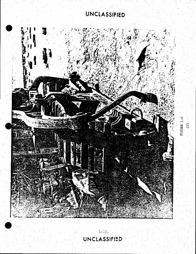
• . I i I ,_ . •*
,;: f ~ ., ,, . ". ,. . (•1 • ...
~~ . ·r·
.J I ., :;-,. ;t· .
•
UNCLASSIFIED
1 .... • • ",~ ,;
. (l• ••• . ' ... ": , \ J ,..,. • . .. ,. r· 1 '·, .
' v .. ' ... ..... .
l-l3l
UNCLASSIFIED
·, . .. .,

UNCLASSIFIED .,
• UNCLASSIFIED

•
•
•
SUPPLEMENT 2
PROJECT RAVE DOUGHNUT
REPORT OF TACTICAL
EVALUATION OF PROJECT AIRCRAFT
AS DETERMINED :BY
TEE UNITED STATES NAVY
(This page Unclassified)
(Reve:::"se Ela.nk)

•
•
•

•
•
•
"CONDUCT AN OPERATIONAL INVESTIGATION OF TBE TACTICAL
EMPLOlliENT 011' NAVY COMBAT ilRPLANES AND THEIR
ASSOCIATED WEAPONS SYSTEMS AGAINST TBE MIG-21"
2-l

List of References
(a) Foreign Technology Division, U.S. Air Force Systems Command 765-243266 Secret publication of 19 November 1965
6 "Fishbed
Weapon System (U)".
(b) Defense Intelligence Agency ST-E3A-1-64, Secret publication of 1 July 1961 6 "Sino-Soviet Bloc A I C Technical Characteristics and Performance Handbook (U)".
(c) NAVAlR 01-245FDB-1, of 1 November 1966, "NATOPS Flight Manual F-4B (U)".
(d) NAVAIR 01-245FDB-1A, Confidi:mtial publication of 1 November 1967, "Supplement to NATOPS Flight Manual (U)".
(e) NAVAIR 01-245FDD-1, of 15 Jun 1967, "NATOPS Flight Manual F-4J (U)".
(f) NAVAIR 01-245FDD-1A, Confidential publication of 15 June 1967, "Supplement to NATOPS Flight Manual F-4J (U)".
(g) NAVAIR 01-245FDB-1 T, Confidential publication of 1 July 1967, "F-4 Tactical Manual (U)".
(h) NAVAIR 01-235FDB-1T(A), Secret publication of 1 July 1967, "Supplement to F-4 Tactical Manual (U)".
(i) NAVAIR 01-45HHD-1, of 1 November 1964, "NATOPS Flight Manual F-8D/E (U)".
(j) NAVAIR 01-45HHD-1B, Confidential publication of 1 May 1965, Supplement to NATOPS Flight Manual F-8D/E (U)".
(k) NAVAIR Ol-45HHA-1T, Confidential publication of 15 April 1967, "F-8 Tactical Manual (U)".
(1) NAVAIR 01-45HHA-1T(A), Secret publication of 15 April 1967, "Supplement to F-8 Tactical Manual (U)".
2-2
Ut~LASSfiED
•
•
•

•
•
•
(m) NAVAIR 01-40ABE-1, of 15 February 1967, "NATOPS Flight Manual A-4/TA-4 (U)".
(n) NAVAIR 01-40AV-1T, Confidential publication of 1 April1967, "A-4/ TA-4 Tactical Manual (U)".
(o) NAVAIR 01-85ADA-1, of 1 December 1967, "NATOPS Flight Manual A-6A (U)".
(p) NAVAIR 01-85ADA-1T, Confidential publication of 15 December 1967, "A-6 Tactical Manual (U)".
(q) NAVAIR 01-45AAA-1, of 1 January 1968, "NATOPS Flight Manual A-7 (U)".
(r) NAVAIR 01-45AAA-1 T, Confidential publication, of 15 April 1968, "A-7 Tactical Manual (U)".
(s) Weapons System Evaluation Group (WSEG) Secret Report #116, of 20 October 1967, "Account of F-4 and F-8 Events prior to March 1967 (U)".
(t) Defense Intelligence Agency ST-HB-05-1-66INT, Secret publication of 1 June 1966, "Radar Handbook Eurasian Communist Countries (U)''.
(u) Air Proving Ground Center TR-66-4 Vol II (Part 4), Secret Publication, of December 1966, "Energy Maneuverability: USAF and USN Aircraft in Clean Configuration (U)".
(v) Air Proving Ground Center TR-66-4 Vol II, (Part B), Secret Publication, of December 1966, "Energy Maneuverability: USSR Aircraft in Clean Configuration (U)".
(w) TAC Analysis Bulletin Vol 67·5, Secret Publication of 27 July 1967 (U)" •
2-3
~~pJIIED

Previously Known Data
(S) References (a) and (b) provided detailed technical information on the MIG-21. Various performance and weapons system capabilities were delineated.
(U) References (c) and (d) provided aircraft and weapons· system description and operating limitations for the F-4B airplane.
(U) References (e) and (f) provided airplane and weapons system description, and operating limitations for the F-4J airplane.
(U) References (g) and (h) provided F-4 air combat tactics and recommended weapons system employment against the MIG-21.
(U) References (i) and (j) provided airplane and weapons system description and operating limitations for the F-8E airplane.
(U) References (k) and (1) provided F-8 air combat tactics and recommended weapons system employment.
(U) References (m) and (n) provided airplane description, operating limitations, and recommended defensive maneuvers for the A -4 airplane.
(U) References (o) and (p) provided airplane description, operating limitations, and recommended defensive maneuvers for the A-6 airplane.
(U) References (q) and (r) provided airplane description, operating limitations, and recommended defensive maneuvers for the A-7 airplane.
(S) Reference (s) provided a large sampling of air-to-air engagements with MIG type airplanes in SEA (Southeast Asia). It indicated extensive use of the MIG-21 as a point interceptor and showed relatively few engagements where the MIG-21 was employed at maximum performance in a prolonged, close-in, turning flight, In addition,
2-4
•
•
•

•
•
•
reference (q) provided guidance in determining altitude parameters for typical encounters during this project.
(S} Reference (t) was used to determine the characteristics and capabilities of the High Fix radar (KVANT) installed in the MIG-21 and to acquire information relative to the radar target size of the MIG-21.
(S) References (u) and (v) compared maneuvering capabilities of Soviet airplanes to USN I USAF airplanes and was used to assist in determining points of relative strength and weakness of the MIG-21 during this project. Reference (v) indicated that the MIG-21 possessed a zoom capability equal to or greater than any Free World fighter.
(S) Reference (w) characterized the MIG-21 as a point interceptor, possessing little or no slow speed maneuvering capability. It was based on pilot opinion, after two flights, with limited knowledge of the airplane's handling characteristics •

List of Acronyms and Abbreviations
A/B
ACM
AERO-lA
AFFTC
AGL
AIM-7E
AIM-7E-2
AIM-9B/D
AMCS
ANIAPR-25
APG-59
APQ-72
APQ-94
ATOLL
AWG-10
Bingo
BIN
CNO
COMOPTEVFOR
Afterburner
Air Combat Maneuvering
F-4B Missile Control System
Air Force Flight Test Center
Above Ground Level
SPARROW Ill Missile
SPARROW III (dogfight) Missile
SIDEWINDER Missile
Airborne Missile Control System
Radar Homing and Warning System
F-4J Radar
F-4B Radar .
F-8E Radar
Soviet Air-to-Air Infrared Missile
F-4J Missile Control System
Minimum fuel state required for safe return to base
Bombardier IN avigator
Chief of Naval Operations
Commander Operational Test and Evaluation Force
2-6
~-~~~A $~FIE 0
•
•
•

• CRT
cw
DIA
DRV
EGT
EI
FFAR
Free F-4
FTD
g
• Have Doughnut
HEI
I Band
IMN
IR
KCAS
KIAS
KTAS
MBC
MIG-21
•
UNCLASSIFIED
Combat Rated Thrust
Continuous Wave
Defense Intelligence Agency
Democratic Republic of Vietnam
Exhaust Gas Temperature
Electronic Intelligence
Folding Fin Aircraft Rocket
Tactical Wingman
Foreign Technology Division of Air Force Systems Command
Acceleration due to gravity
Project Title
High Explosive Incendiary
Radio Frequency Energy (8. 000 to 10.000 KC)
Indicated Mach Number
Infrared Radiation
Knots Calibrated Airspeed
Knots Indicated Airspeed
Knots True Airspeed
Main Be am Clutter
MIG-21 F-13 (Fishbed C/E)
2-7
UNCLASSIFIED

MM
NATC
NATOPS
NM
Oblique Loop
Padlock
PLM
PPS
PRF
PD
q
SEA
TAC
TAC LEAD
TAC WING
TCA
UHF
VA
UNCLASSIFIED
Millimeter
Naval Air Test Center
Naval Aviation Training and Operational Standardization Program
Nautical Miles
An overhead maneuver performed just off the true vertical. An angle of bank is held to facilitate maintaining visual contact with a target in the rear hemisphere.
A ~ookout technique that requires looking solely at the target once it has been visually acquired.
Pilot Lock-On Modification
Pulses Per Second
Pulse Repetition Frequency
Pulse Doppler
Dynamic Pressure
Southeast Asia
Tactical Air Command
Tactical Lead
Tactical Wing
Track Crossing Angle
Ultra High Frequency (Radio)
Fixed wing, heavier than air, attack airplanes
2-8
UNCLASSIFIED
•
•
•

UN ci.A;SS1F4fo
• Vc Closing Velocity
VF Fixed wing, heavier than air, fighter airplanes
VID Visual Identification
•
•

DESCRIPTION OF MATERIAL
1. (S) MIG-21 F-13 FISHBED C/E
A. The MIG-21 is a small, single place, Mach 2, clear air mass interceptor and ground support airplane. The overall design philosophy of the MIG-21 is one of engineering simplicity and reliability. The airplane is configured with a 57 degree swept delta wing and swept horizontal and vertical tail. Figure 2-l illustrates the MIG-21's plan form.
......, . ') ., .rlgure c:.-.L
?ISE3E:D E Plan ?orr.1
(S-Gr-1)
2-lC;
•
•
•

•
•
•
The fuselage is 41.1 feet long (without pitot boom) and the wing span is 23.5 feet. Empty i'l'eight is ll ,100 lbs. A three position, translating, double angle inlet cone is installed for supersonic flight. The cone extends from the retracted position to an intermediate position at 1.5 IMN and to the full forward position at 1.9 IMN. The cone is normally automatic, however, it may be manually positioned by the pilot from the retracted position to the 1.5 or the 1.9 IMN position.
B. The MIG-21 power plant is a Type 37F twin spool turbojet equipped with a variable thrust afterburner. The engine is 181 inches long with a diameter of 35.7 inches. The engine develops approximately 8,450 lbs of thrust at military power and approximately 12,650 lbs of thrust at maximum afterburner power.
C. The MIG-21 flight control system consists of a manual rudder, hydraulically boosted manual ailerons, and an irreversible horizontal stabilizer. The main hydraulic system operates at 1200-1400 psi and powers the aileron boost and horizontal stabilizer. No manual back-up control is provided to the horizontal stabilizer. To prevent over controlling at high speeds, an automatic control alters the gear ratio from the control level to the stabilizer to decrease the range of deflection required of the stabilizer . No stability augmentation, aileron trim, or rudder trim is provided.
D. The hydraulically actuated speed brakes are located on the underside of the fuselage, two forward and one aft.
E. The landing gear is conventional tricycle type with selectable two or three wheel, air-operated brakes. Braking is actuated by a lever on the control stick and is controlled by rudder to the desired wheel.
F. The fuel system capacity is approximately 4,500 pounds of JP-5. The fuselage cells are non self-sealing bladder type. Wing fuel is stored in a "wet wing."
G. The airplane uses a simple, single button, selfcontained, electrical battery starting system.
H. The airstart system incorporates an autonomous oxygen supply and is designed fo: restarts~up t~~3~ 1 ~~0 feet. Sufficient oxygen is avai~able for LOUr ~~ ·:~=~~~~~ airstarts of 30 secon~s duration each. During ~~: 1 ~~a~ 1
v.:.•·o
cycle, aviation gasollne is supplied from a spev.:.a._ GanK .
2-ll

I. The MIG-21 cockpit is armor plated. Armor plating is installed behind the pilot's seat, forward of the instrument panel and aft of the forward wind screen.
J. The MIG-21 engine compartment is protected by a flame detecting and fire extinguishing system. The system was designed to detect visible flame and not heat. The operation of the sensor is based on the ability of a flame to conduct an electrical current due to ionization accompanying the chemical reaction which occurs when flame is formed. When a flame appears, an airgap becomes electrically conductive and closes a circuit to actuate the alarm. The signal from the sensors is amplified and a warning light in the cockpit indicates a fire. Pilot actuation of the fire extinguisher button in the cockpit fires a squib valve releasing fire extinguishing fluid which is disbursed by a steel annular spray ring located around the engine.
K. The canopy is pneumatically operated by controls on the left canopy sill and externally from the left forward nose section. The pilot positions two levers to lower and lock the canopy and pressurize the canopy seal. There is no warning light to indicate a canopy unlock condition. Canopy movement occurs approximately 10 seconds after selection. The canopy is designed to semi-encapsulate the pilot during the normal ejection sequence. Alternate controls allow for separate jettison of the canopy. The flap above the pilot's headrest shields the pilot's head from the canopy during ejection.
L. The MIG-21 cockpit reflects the Soviet concept of design simplicity. The grouping of switches, controls, instruments, and warning lights is poor, giving the cockpit a cluttered appearance. Close pilot attention is required when moving switches, yet little pilot monitoring or control of airplane systems is required.
M. The MIG-21 is configured with a KVANT, range only radar, designated SRD-5MK. This set is known as HIGH FIX within the intelligence community. The High Fix ARO (Aircraft Range Only) radar set operates in the I-band range (nominal 9370 MC) with a radio frequency power output of 5.7 kw. A pulse width of 0.5 microseconds at a pulse repetition rate of 800 ± 100 PPS (Pulses Per Second) is employed. Two modes of operation are available. Mode A, with a beam width of 18 degrees and a maximum range of 1.6 NM (Nautical Miles), is utilized for determining target range when firing the ~annon or rockets. Mode B, with a 6-degree beam width and a 3.7 NM maximum range, is used for ranging when firing ATOLL missiles.
2-12
•
•
•

•
•
•
N. The sight system in the MIG-21 is an ASP-5ND lead computing gunsight. In the cannon or rocket mode of operation, range information is supplied by the High Fix radar to the gyro pipper. In event of radar failure, fixed range inputs are available from 650 to 6600 feet.
0. Fixed armament on the MIG-21 is one NR-30 30-mm cannon faired into the fuselage under the right-ha~d side of the pilot's cockpit. The cannon has a linear action with a mechanical feed chute which roughly follows the contour of the airplane's outer fuselage skin between the skin and the internal fuel tank. Firing rate is 850 rounds per minute with a muzzle velocity of approximately 2,500 feet per second.
P. External stores are provided on two wing-mounted stations and one centerline station. Each removable wing station is capable of carrying one ATOLL missile, or one bomb up to 1100 pounds, or one 16-shot FFAR (Folding Fin AircraftRocket) pod. The permanently mounted centerline station is capable of carrying one 130-gallon jetisonable fuel tank or an 1100-pound bomb. Tail warning receiver (SIRENA) was not installed. Additional airplane description is contained in references (a) and (b).
2. (C) F-4B PHAN~OM II
A. The F-4B is a two-place, supersonic, long range, carrier-based, all-weather fighter, built by McDonnellDouglas Corporation. It is designed for intermediate and long range, high altitude interception using missiles, and for intermediate or long range attack missions delivering nuclear or conventional weapons. It is powered by two single rotor, variable stator, General Electric J79-GE-8 axial-flow, turbojet engines, each producing 10,900 lbs of thrust at MRT (Military Rated Thrust) and 17,000 lbs at CRT (Combat Rate Thrust). The airplane features a low-mounted, swept back wing with positive dihedral at the wing tips and a one piece stabilator with cathedra~ mounted low on the fuselage. The wings have hydraulically operated leading and trailing edge flaps, ailerons, spoilers and speed brakes. All control surfaces are positioned by irreversible, hydraulic powered, control cylinders to provide desired control effectiveness through the entire speed range. A selfcharging pneumatic system provides normal and emergency canopy operation, as well as emergency operation of the landing gear and wing flaps. The pressurized cockpit is enclosed by two aft hingeing clamshell canopies .

B. The AMCS (Airborne Missile Control System) consists of: the radar set AN-APQ-72, radar set group AN/APA-157, and missile firing circuits. The airplane is capable of carrying a missile armament load of six AIM-7E (Sparrow III) missiles or a mixed load of four AIM-7E and four AIM-9B/D (Sidewider) missiles. Sparrow missiles are carried on four semi-submerged fuselage stations and two wing pylons. The fuselage stations employ AER0-7A guided missile launchers and are used for AIM-7 missiles only. LAU-17 pylons are AMCS provides the necessary pre-launch tuning signals to the AIM-7 missile, supplies the pilot with steering and launch range information, and illuminates the target with the CW (Continuous Wave) energy necessary for AIM-7 guidance after launch. Two AIM-9 missiles can be carried on each wing pylon by attaching LAU-17A or AER0-3A missile launchers. In addition the AMCS provides the pilot with steering information that can be used to maneuver the airplane into an AIM-9 launch zone. The AMCS will locate, acquire, and track a selected airborne target under all weather and countermeasures conditions.
C. The F-4B used in this test was configured with PLM (Pilot Lock-On Modification). PLM allows the pilot, by visually boresighting the target, to lock-on any target out to 5 miles and attain a full system track independent of RIO action. The system is initiated by actuation of the nose gear steering button and features a 5-miles radar scope presentation and automatic range gate sweep, the direction of which is selectable from the cockpit (in or out). This feature allows the range gate to acquire the target prior to reaching the altitude line.
D. An AN/APR-25 radar homing and warning receiver was installed.
E. Physical dimensions of the F-4B airplane are.
Wing Span Length Height (to top of fin) Basic Operating Weight (Dry) is
38 feet 5 inches 58 feet 3 inches 16 feet 3 inches 29,000 pounds
Mor~ detailed information is contained in references (c) and (d).
3. (C) F-4J PHANTOM II
A. The F-4J airplane is a two place, supersonic, long range, all weather fighter built by McDonnell-Douglas Corpo~ation. The airplane is designed for intermediate and long range hlgh altitude interceptions, using missiles as the principle armament and for intermediate or long range attack missions, to deliver nuclear or conventional weapons. The airplane is powered by ~wo
2-1.4.
~ .•' ~ p- •
•
•

•
•
•
single rotor, axial flow, variable stator, turbojet J79-GE-10 engines with afterburner. J79-GE-10 engines develop 11,870 pounds of thrust at military power and 17,900 pounds of thrust at full afterburner. Other airframe characteristics are similar to the F-4B.
B. The missile control system is designated AN/AWG-10 and consists of AN/APG-59 radar set, OA-6822/AWG-10 missile control group, and missile firing circuits. The F-4J is capable of carrying the same missile load as the F-4B. The primary purpose of the AN/AWG-10 is to provide the necessary pre-launch tuning signals to AIM-7 missiles, supply the pilot with steering and launch zone information, and illuminate the target with CW energy necessary for guidance after launch. The AN/AWG-10 will locate, allow lock-on, and track a selected target under all weather and countermeasures conditions.
C. The AN/APG-59 is an airborne intercept radar which incorporates characteristics of several different types of radars; coherent high-prf pulse doppler radar, long range pulse radar with pulse expansion and compression (chirp) features, short range pulse radar, monopulse radar, and a CW illuminator for AIM-7 missile guidance. The pulse mode provides range and azimuth information to a particular target. The pulse doppler search mode provides velocity and azimuth target information. Pulse doppler allows radar discrimination between low flying targets and ground return .
D. Dimensions of the F-4J are identical to the F-4B. Basic operating weight (dry) is 30,280 pounds. More detailed information is contained in references (.e) and (f).
4. (C) F-8E CRUSADER
A. The F-8E is a single place, single engine, carrier based, supersonic fighter airplane manufactured by Ling-Temco Vought. It is powered by a J-57-P-20A engine which produces 11,400 pounds of thrust at MRT and 18,000 pounds at CRT. Flight controls are fully powered and irreversible. Air-to-air weapons include four MK12, 20 MM cannons, each with a firing rate of 1,000 rounds per minute. Approximately 500 usable rounds can be carried. In addition, up to four AIM-9 Sidewinder missiles can be carried on external fuselage stations. Two detachable wing pylons permit carriage of bombs and rockets. Fuselage stations may be used for rockets when AIM-9 missiles are not carried.
B. The airplane is equipped with the APQ-94 rada~. In addition to normal search a~d track capabilities, the B~: (Boresight Acquisition Tracking) mode of ope~ation locks ~he antenna on radar boresight and allows the ra~ge strobe tc automatically sweep from 60C feet tc 5 ~~les. The radar auto~atically locks up and shifts to full tra~k when a target is

detected in the sweep. A missile launch computer illuminates an in-range light when within aerodynamic range of the missile carried. The radar also provides range information to the lead computing gunsight.
c. Principal dimensions are.
Length 55 feet Wing Span 35 feet Height 16 feet Weight 19,000 pounds
D. A more detailed description may be found in references (g) and (h).
5. (U) A-4F SKYHAWK
A. The Navy Model A-4F is a single place, single engine, carrier based, attack airplane with a modified delta planform wing manufactured by McDonnell-Douglas Corporation. It is powered by a J52-P-8A gas turbine engine producing a sea-level static thrust rating of 9,300 pounds. Designed as a high performance, light weight attack airplane, it mounts two 20 MM guns internally and carries a variety of external stores. The test was conducted using the A-4F with a 300 gallon centerline drop ·tank.
( m).
B. Principal dimensions are.
Length Wing -span Weight Height
39 feet, 8-1/2 inches 27 feet, 6 inches 19,000 pounds 16 feet
C. A more detailed description may be found in reference
6. (U) A-6A INTRUDER
A. The A-6A is a subsonic, two place, all weather, carrier based attack airplane manufactured by Grumman Aircraft Engineering Company. The airplane is powered by two J52-P-8A, axial flow, turbojet engines; each providing 8,200 pounds military rated static thrust. The design of the airplane provides for an extremely low-level attack capability to minimize the effectiveness of enemy defense systems based on radar derived target information. The basic airplane is configured with four wing pylons and a centerline store station. The wing pylons also have mounting provisions for guided missile launchers.
2-16
••
•
•
•

•
•
•
B . Dimensions:
Length 54 feet, 9 inches Height 16 feet, 2 inches Wing Span 53 feet Weight 28,600 pounds
c. A more detailed description ( o).
may be found in reference
7. (U) A-7A CORSAIR II
A. The A-7A is a single place, single engine, carrier based, light attack airplane manufactured by Ling-Temco Vought. The airplane has a swept, shoulder mounted wing with a marked degree of negative dihedral. The wing contains an integral fuel cell and has flaps on the leading and trailing edges. An all moving unit horizontal tail provides longitudinal control. Fixed armament consists of two 20 MM cannons.
B. Dimensions.
Length Height Wing Span Weight
39 feet, 7 inches 14 feet, 6 inches 46 feet 15,978 pounds
8. (C) AIM-7 GUIDED MISSILES. The AIM-7 missile is a supersonic air-to-air homing missile. Guidance is supplied by the transmitted CW signal from the launching airplane. The missile compares the CW signal received from the launching airplane with CW signal reflected from the target to lock-on and track the target by means of proportional navigation.
9. (C) AIM-9 GUIDED MISSILE. The AIM-9B/D missiles are supersonic air-to-air homing missiles employing passive infrared target radiation for guidance. The missiles use the infrared energy emitted by the target to lock-on and track the target. An audible tone is provided to the aircrew when target detection is achieved.
10. (C) RADAR HOMING AND WARNING SET AN/APR-25. The AN/APR-25 is a passive ECM (Electronic Countermeasures) set and consists of warning receiver, threat indicators, and an audio system. The radar homing and warning set indicates threat bearing relative to airplane heading, relative signal strength, and the type of emitting activity. Threat signals are discriminated from non-threat signals by radio frequency signal strength, pulse repetition frequency, and antenna scan rate. Threats are displayed on the strobe display scopes and en threat indicatcrs in each cockpit .
2-17

PURPOSE OF THE TEST
1. (S) The purpose of the test was to conduct an operational investigation of the tactical employment of Navy combat airplanes and associated weapons systems against the MIG-21 F-13 FISHBED E airplane. The specific objectives of this evaluation were:
A. To determine the effectiveness of existing tactics employed by Navy combat airplanes and associated weapons systems against the MIG-21.
B. To exploit the tactical capabilities and limitations of the MIG-21 in the air-to-air environment when employed against Navy combat airplanes.
C. To optimize existing tactics and develop new tactics as necessary to defeat the MIG-21.
D. To evaluate the design, performance, and operating characteristics of the MIG-21.
CONDUCT OF THE TEST
1. (S) This test was conducted to investigate the capabilities of Naval combat airplanes and associated weapons systems when employed against the MIG-21. The test investigated a limited area of air-to-air warfare to determine the areas of comparative strength and weakness, validate existing tactics, and determine future tactical doctrine.
2. (S) CHRONOLOGY. The MIG-21 was first flown on 8 February with the final flight on 30 March 1968. During the project, 134 sorties were scheduled and 102 were flown. Of the sorties not flown, 11 were cancelled because of maintenance. The relatively high number of weather cancellations were due to the stringent weather requirements for the tactical evaluation. The operating area had to be clear of clouds below 20,000 feet with 5 miles visibility. Weather during the first 10 days of the project accounted for the great majority of weather cancellations. Several sorties cancelled because of maintenance were preventative in nature; due, in part, to lack of familiarity with the MIG-21 systems. A summary of the scheduled and the cancelled flights is contained in Table 2-1.
3. (S) Forty-six tactical flights were flown with the MIG-21 flying against USN/USAF fighter and attack airplanes in a high q, high g, maneuvering environment simulating the combat conditions existing in SEA. The remainder of the flights were devoted to flight test and technical intelligence collection missior.s. Tactical mission briefs, in-flight comments by participat~ng aircrews, post mission briefs and mission summaries were tape recorded and analyzed.
····"•' ~18 .. ( :t ~:'_. a .-e:
•
•
•
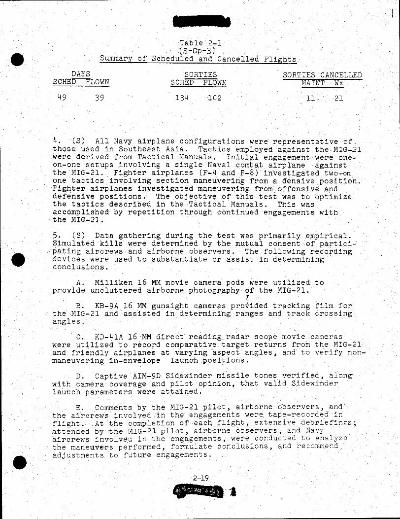
•
•
•
Table 2-1 (S-Gp-3)
Summary of Scheduled and Cancelled Flights
DAYS SCHEo--FLOWN
SORTIES SCHED FLOWN
SORTIES CANCELLED MAINT Wx
49 39 134 102 11 21
4. (S) All Navy airplane configurations were representative of those used in Southeast Asia. Tactics employed against the MIG-21 were derived from Tactical Manuals. Initial engagement were oneon-one setups involving a single Naval combat airplane against the MIG-21. Fighter airplanes (F-4 and F-8) investigated two-on one tactics involving section maneuvering from a densive position. Fighter airplanes investigated maneuvering from offensive and defensive positions. The objective of this test was to optimize the tactics described in the Tactical Manuals. This was accomplished by repetition through continued engagements with the MIG-21.
5. (S) Data gathering during the test was primarily empirical. Simulated kills were determined by the mutual consent of participating aircrews and airborne observers. The following recording devices were used to substantiate or assist in determining conclusions.
A. Milliken 16 MM movie camera pods were utilized to provide uncluttered airborne photography of the MIG-21.
r B. KB-9A 16 MM gunsight cameras provided tracking film for
the MIG-21 and assisted in determining ranges and track crossing angles.
C. KD-41A 16 MM direct reading radar scope movie cameras were utilized to record comparative target returns from the MIG-21 and friendly airplanes at varying aspect angles, and to verify nonmaneuvering in-envelope launch positions.
D. Captive AIM-9D Sidewinder missile tones verified, along with camera coverage and pilot opinion, that valid Sidewinder launch parameters were attained.
E. Comments by the MIG-21 pilot, airborne observers, and the aircrews involved in the engagements were tape-recorded in flight. At the completion of each flight, extensive debriefin~s; attended by the MIG-21 pilot, airborne observers, and Navy aircrews involved in the engagements, were conducted to analyze the maneuvers performed, formulate conclusions, and recorr~e~d adjustments to future engagements .
2-19

F. During the course of the project, the conduct of future flights was greatly influenced by the results of previous flights. The tactics employed as the project progressed were the result of past experiences with the MIG-21.
6. (S) All tactical engagements were planned to closely approximate engagement criteria encountered in SEA. The MIG-21 engaged at fuel weights expected within 75 NM of his home base and F-4/F-8 airplanes engaged at fuel weights normally on board over the DRV. "Bingo" fuel states assumed a 50-75 NM flight to home base for the MIG-21 and a 90-110 NM flight to an aerial tanker for Navy airplanes.
7. (S) Standard rules of engagement prevailed where applicable. A positive visual identification was required prior to a simulated missile or gun shot. A satisfactory shot was assumed when a missile was locked on and in-envelope parameters were attained. A satisfactory gun shot was assumed when the attacking airplane was tracking within 2,000 feet of the target. Not all engagements were terminated following the first successful missile or gun shot. Engagements were terminated if two-way communication was lost or the objective was attained.
RESULTS AND DISCUSSION
MIG-21
1. ( S) The MIG-21 F-13 FISHBED E is a simple and highly reliable Mach 2 airplane. The Air Force Flight Tes~ Center completed a ground test and performance and stability evaluation of the MIG-21. See Have Doughnut Vol I, Technical for this report.
2. (S) No rna or maintenance malf~nctions occurred durin the 102 MIG-21 flights. Enclosure 1 contains a summary of the maintenance effort expended on the MIG-21 during the project. The tires, wheel brakes, and engine oil filter were changed after approximately 50 flights. Three minor engine EGT (Exhaust Gas Temperature) system problems occurred. One small hydraulic leak was noted. Some difficulty was experienced during the initial flights with landing gear retraction, but did not affect airplane availability. The canopy operating system was potentially weak, but failure was minimized by careful actuation of the canopy controls. ·
3. (S) MIG-21 servicing requirements were minimal. A crew of six men was assigned to service and maintain the MIG-21. Servicing between flights was often completed in 30 minutes without difficulty. All servicing receptacles were readily accessible through individual access panels.
2-20
•
•
•

•
•
•
4. (S) The MIG-21 systems were unsophisticated and were designed for high reliability. No complicated servicing equipment was required. The MIG-21 had a self-contained electrical starting unit. The main and booster hydraulic systems were pressurized to a maximum working pressure of 3100 psi, but normally operated at 1200 to 1400 psi; as compared to constant high pressures in U. S. airplanes. The pneumatic system was a ground charged, highly reliable system rated at 1800 psi. The fuel system was gravity filled and pressurized by sixth stage engine compressor air. One boost pump supplied fuel directly to the fuel control. The 28V electrical system contained a battery, starter-generator and an inverter. Emergency electrical power was available from two batteries.
5. (S) The MIG-21 was corrosion free. The skin of the airplane was coated with a clear, lacquer type covering that did not crack, peel, or deteriorate. This substance was placed under analysis by the Foreign Technology Division, U. S. Air Force Systems Command.
6. (S) The MIG-21 cockpit noise level was low .. Cockpit pressurization and air conditioning were provided by compressor air and heat exchanging. The automatic cockpit temperature control was preset prior to take off and could not be reset in flight. Manual air temperature control was available to the pilot in flight. No fog or snow was blown into the cockpit through the system on any flight. The cockpit noise level was much lower than the F-4 or F-8 airplanes.
7. (S) . The MIG-21 pilot seat positioning appeared to enhance pilot g tolerance. When seated in the cockpit the pilot's knees are raised and his legs pointed more forward than down. As a result the pilot's g tolerance appears to be raised approximately 1 g. Figure 2-2 ~llustrates the MIG-21 pilot's seating position.
8. (S) The MIG-21 had poor cockpit visibility. The combination of a bullet proof glass plate, the gunsight combining glass, and the canopy restricted visibility through the forward windscreen to 3 to 5 NM against F-4/F-8 sized targets. Visibility through the forward side panels and the remainder of the forward hinged, clamshell canopy restricted the pilot's head movements resulting in a 50 degree blind cone to the rear. The canopy rails were much higher than in U. S. airplanes and limited look down at the 3 and 9 o'clock positions to 20 degrees. Excellent forward visibility was obtained in the MIG-21 by "S" turning and looking through the forward side panels .
2-21

...
Figure 2-2
MIG-21 Pilot Seating Position
(S-Gp-3)
9. (S) The MIG-21 cockpit layout and seat mechanization were classed as generally poor. A ladder was necessary to gain access to the cockpit. The pilot stepped on the seat, which contained the parachute; supported himself on the canopy rails; and carefully positioned his feet on the rudder bars. -He then-lowered himself into the seat. Great care was taken as the pilot positioned his feet on the rudder bars because of the limited space between the leg restraint mechanism, center pedestal, and the lower instrument panel. Rudder bars were manually adjusted by maintenance personnel prior to pilot entry. Seat comfort was marginal due to the parachute harness back strap arrangement. Seat adjustment was accomplished by an electrical actuator which moved the seat up and down. The canopy had to be closed when taxiing. Limited over-the-nose vision and reduced acuity through the forward windscreen resulted in poor visibility when tracking. The narrow canopy restricted head movement. Ejection triggers on each armrest appeared easy to operate and were readily accessible. Donning the parachute and integral seat restraint harness required one to two minutes. Ea8h leg strap on the seat-type parachute was positioned over the leg and threaded through a harness loop and seat pan slot at the rear of the seat, then into a central harness connector. Finally, the pilot snapped the right shoulder strap into the connector and attached the oxygen, anti-g
•
•
•

•
•
•
suit, and communications leads. The personnel lead group, although bulky, did not restrict pilot movement or cause discomfort. A ratchet handle located on the right side of the seat allowed the pilot to tighten the harness and restraint mechanism to a high tension. Shoulder harness slack was adjusted by a release/locking lever located on the left side of the pilot seat.
10. (S) The MIG-21 cockpit switches were considered poorly located. With slight slack in the shoulder harness, all switches and controls could be actuated by the pilot. With the shoulder harness locked in the fully retracted position, the pilot had . some difficulty reaching the forward left and right extremities; i.e., landing gear panel and indicator light dimmer control. Identifying placards for switches located on the right vertical console were positioned above each switch. This inconsistency was confusing to an inexperienced MIG-21 pilot and caused identification difficulty. Guards and covers for switches and buttons were good. Armament switches, controls, and monitoring lights for bombs, rockets, cannon, and missiles were located at random throughout the cockpit. Despite this scattered switch location, very little pilot action was required to set up the desired armament. When converting from a missile to cannon attack, the pilot had to reposition the following:
A. Missile- Cannon switch to "cannon."
B. Sight cage lever - Uncage (this can be accomplished by alternate use of the electrical cage function).
11. (S) The MIG-21's instruments were poorly grouped and located.
A. Pilot crosscheck required total panel scan instead of localized scanning. The Mach meter, vertical speed, and turn indicators were positioned on the right half of the instrument panel; while the attitude indicator, airspeed, altirnete~, and compass were on the left. Engine instrument grouping was good. The engine monitoring gauges (tachometer, EGT, oil pressure and fuel totalizer) were located on the right lower half of the instrument panel. Readability and interpretation of these instruments were good.
B. Warning lights were poorly located and difficult to interpret. Landing gear warning lights were on the lower left subpanel. The marker beacon, nose cone position i~dicator, "stabilizer ratio set for land" light, and trim war:li'1~ placards were i::1 the center warning panel. Fire warni!lS a~d ::~e~ lights were in t~e upper right portion of the instru~snt pa~~:. D ~ ~ ..... . ·n ~~g~'-s ove""' ~t ,+» •• -;~ ~ ........ -~.....--.!-.•• ,.,,_.,~-,...; ..._mneSS 0 .. :..,:le I·Ia.n:::L g .i..o. ·.l.., , '"' ·• a. .:.~~- -·:·~--"-- :: ,' vo::.~.:-c:::..-
interpretation iiff!~u!ty. Coler coding ~~= ~~c=~=~~:e~: throug~out the war~in;/nonitor indicators a~d ~e~-~:l:~ei
2-23

warning light may or may not have been a normal condition. The monitoring and warning light system was adequate for providing vital information to the pilot.
C. Controls and switches located on the left and right consoles and center pedestal were generally rated good to fair. Identification and accessibility of switches on the center pedestal was marginal because the control stick blocked the pilot's view. Left console switches were provided with a "gang bar" to facilitate pilot actuation. Switches were arranged so that the ON position was either a forward or upward movement of the switch control. Pressure gauges on the vertical instrument subpanels were difficult to interpret. Figure 2-3 illustrates the MIG-21 instrument panel.
Ins~rument Panel
(S-Gp-1)
2-24
•
•
•

•
•
•
D. Manual control of the nose cone, stabilizer ratio, and intake shutter doors provided pilot override capability for these normally automatic systems. Emergency airstart and landing gear controls were adequate, but required conc~ntrat~d effort to actuate. An emergency hydraulic pumplng unlt was incorporated for limited stabilizer control in the event of primary and boost pump failure. This system was automatically actuated or could be manually selected by the pilot. Aileron control was effected by manual action if the booster system was lost.
E. Speed brake, gunsight electrical cage, and trim armament fire buttons were located on the control stick grip. Actuation of electrical cage, when pressing the trigger, was somewhat awkward; but did not necessarily limit the pilot's ability to operate the systems. The trigger was normally stowed in an upright position and was unfolded for operation. The brake handle arrangement was poor and of antiquated design.
F. Throttle controls were rated good to fair. The positive lock lever for idle was good since inadvertent stopcocking of the engine was nearly impossible. The afterburner engaging locking levers initially caused difficulty for the pilot because of the determined effort required to engage and disengage afterburner. Figure 2-4 illustrates the MIG-21 throttle quadrant .
12. (S) The MIG-21 appeared to have a high speed ejection capability. By semi-encapsulating the pilot with the canopy during ejection, high speed bailouts appeared to be possible without serious pilot injury. The system was designed to operate at speeds up to 595 KIAS (at sea level) and up to 2.05 INM at altitude. Figure 2-5 illustrates the ejection system sequence.
13. ( S) The MIG-21 pilot was protected by armor platin$. Armor plating around the pilot was present as indicated below:
Headrest Rear Plate Front Plate Glass Shield
.68 inches
.63 inches
.4 . inches 2.5 inches
thick thick thick thick
Review of all available combat gun camera film indicated that, although the MIG-21 had a tendency to explode when hit by cannon/missile fire (probably due to wet wing design), the pilot ejected successfully in most cases. Effectiveness of this armor plating apparently contr1butes to the high pilot survivability ~ate. Figure 2-6 illustrates the MIG-21's protective armor &rrangement .
2-25

Retainer of Sight Range Input Data Handle
"CUTOFF" Stop
"IDLING RATING" Stop
Retainer of "CUTOFF" Stop and "IDLING RATING" Stop
Button for M Number Stop Emergency Release
Holding Lever
Slide of Air Brake
~--- Retainer of "MAXIMUM" and "AUGMENTED" Stops
"MAXIMUM RATING" Stop
"MINIMUM AUGMENTED RATING" Stop
"FULL AUGMENTED RATING" Stop
Electro Magnet ZM0-212
Figure 2-4
Throttle Quadrant
(S-Gp-3)
2-26
•
•
•

•
•
1. THE PILOT SQUEEZES THE ARMREST TRIGGERS, ACTU· ATING THE FIRING MECHANISM FOR THE SHOULDER HARNESS AND THE SEAT EJECTION.
2. AFTER SEAT MOVES 1.5 INCH, THE DROGUE CHUTE FIRING MEDiAN ISM IS ENGAGED, DRIVES OUT THE CANOPY PLUG AND PUSHES OUT THE CHUTE.
3. THE SEAT ENGAGES THE CANOPY COVERING THE PILOT. THE TIMING MEDiAN ISM STARTS.
4. THE DROGUE TURNS THE SEAT FOR DECELERATION FORCES.
S. THE MAST WITH THE DROGUE CHUTE IS DISENGAGED AND THE FRONT CANOPY LOCKS RELEASE.
6. THE CANOPY IS TURNED UP AND DISENGAGED FROM THE SEAT. PILOT RESTRAINT LOCKS ARE RELEASED.
7. PILOT'S CHUTE OPENS AUTOMATICALLY AT 13,100 FEET («XXI METERS).
Figure 2-5
Ejection Sequence
(S-Gp-3)
2-27

2
G) -\ . .---··
\
: ) } : . _}
··---I. FRONT ARMOR PLATE 2. BULLET-PROOF GLASS 3. ARMOR PLATED HEADREST
4. REAR ARMOR PLATE
Figure 2-6
Protective Armor (S-Gp-3)
14. (S) A three wheel braking system was incorporated in the MIG-21 design. The nose wheel brake was selected at the pilot's option. This increased the total system braking energy by 20 percent. After landing gear retraction, an automatic feature applied the wheel brakes to prevent tire rotation in the wheel wells.
15. (S) The MIG-21 gunsight radar capabilities were verified. A 3.7 NM maxfmUm detection range in the missile mode and a 1.6 NM maximum detection range in the guns mode were obtained.
16. (S) The MIG-21 gunsight was~ineffective during maneuvering flight. Manual ranging of the gunsight was not smooth or precise. System hysteresis and friction made it virtually impossible to prevent overcontrol of the sight reticle diameter size with the throttle twist grip. Pipper jitter during cannon firing was in excess of 20 mils. Gyro drift when tracking air targets was excessive. At g loads greater than +2.5 the sight reticle drifted to a point near the bottom of the sight combining glass. At very high g loads, the sight reticle disappeared entirely. The sight electrical cage functional was sluggish and slow to respond. During air-to-air tracking, it was necessary to hold the electrical cage button (on the stick grip) until radar lock on occurred. The
2-28
•
•
•

•
•
•
electrical cage button was poorly positioned and difficult to actuate when preparing to fire the cannon. Over-the-nose visibility restrictions limited the useful mil depression to 95 mils. Large lead angles during air-to-ground attacks with bombs, cannon, or rockets were not available. It was not possible to depress the gunsight in the cannon mode of operation as may be required for ground attack at long slant ranges.
17. (S) The MIG-21 30 mm cannon was 100 percent reliable. The gun was fired on five different sorties. On each sortie, ten HEI (high explosive incendiary) rounds were loaded and fired out in a single burst in near one g flight at a ground target. No jams or failures to fire were encountered. The muzzle flash was readily visible at one mile in daylight.
18. (S) The lethality of the 30 mm cannon was demonstrated. A ground attack mission was conducted against a standard, U. S. manufactured bulldozer. The bulldozer was rendered inoperative and irreparable after being hit with one round of 30 mm HEI ammunition.
19. (S) The MIG-21 engine demonstrated slow acceleration, slow afterburner ignition, and minimum smoke emission. The engine of the MIG-21 required approximately 55 seconds from commencing start to idle RPM. Idle to 100 percent RPM required 15 seconds. Afterburner ignition required 2 to 3 seconds from initiation to full CRT. In flight, acceleration from 85 percent to 100 percent RPM required 10 seconds. The afterburner did not ignite until 100 percent RPM was attained. If the throttle was not placed in the full afterburner detent for ignition, a delay of up to 9 seconds was experienced. The fuel used by countries operating the MIG-21 closely approximates U, S. grade JP-1 fuel. During the project, JP-5 fuel was used. The MIG-21 left virtually no smoke trail during the first four flights and the turbine and exhaust sections were free of residue and carbon deposits. Figure 2-7 illustrates the reduced amount of smoke emitting from the MIG-21. After the fifth flight, the MIG-21 started to leave a progressively more visible smoke train at military power and the turbine/exhaust sections began to accumulate carbon deposits similar to those found in all U. S. engines. Afterburner ignition and termination puffs were visible above 15,000 feet and were approximately one-third the size of an F-8E afterburner puff.
20. (S) The MIG-21 VN diagram was verified. Qualitative data points on the MIG-21 VN diagr&~ were reached during the tactical maneuvering phase of the project. Figure 2-8 illustrates the MIG-21 VN diagram .
2-29

• (!) •
• 8
7
8
4
2 v·· I
0....,.,.. j,•"'
......... )',
I
I'. 2
3
I I
/ 1/'
"-.1
j
Figure 2-7 (S-Gp-1)
Smoke Emission
.1 / ,.,
./
.
.... __
. 0 &0 100 1&0 200 2&0 300 3&0 400 460 &00 11110 800 8&0 700
CA!.IBRATED AIRSPEED VN DIAGRAM 30,000 FT.
Figure 2-8 (S-Gp-1)
MIG-21 VN Diagram
2-30
•
•
•

•
•
•
21. (S) The MIG-21 was extremely difficult to acquire visually. From a 0 to 180 degree aspect angle the MIG-21 was most difficult to acquire visually beyond 2 miles. The ability to visually identify the MIG-21 at these aspects beyond 1 NM was remote. No successful head on, simulated AIM-7 missile firings were made once the MIG-21 was engaged. The MIG-21 compared in size to the A-4 and F-5 airplames from a 90 degree aspect angle. Comparative measurement of the MIG-21 and the F-4/F-8 airplanes are as follows.
Wing Span
Fuselage Length
Empty weight (Approx)
MIG-21
23.4'
44.6 1
11,000 lbs
F-8
35.6'
55'
19,800 lbs
F-4
38.4'
58.2'
29,000 lbs
22. (S) The MIG-21 demonstrated a maneuvering capability at speeds as slow as 115 KIAS. Repeated slow speed engagements between the F-4/F-8 airplanes and the MIG-21 demonstrated that the MIG-21 could obtain a higher g loading at comparable airspeeds and maintain controlled flight at slower airspeeds. A comparison of F-4/F-8 and MIG-21 VN diagrams substantiate this performance .
23. (S) The MIG-21 demonstrated no noticeable decrease in performance when two Sidewinder missiles were attached. Two AIM-9B missiles, having the same drag index as two ATOLL missiles, were installed on the MIG-21. The MIG-21 was flown with and without missiles during the tactical exploitation tests with no noticeable performance change. Lateral stability at slow speeds appeared to be slightly improved with missiles installed.
24. (S) The MIG-21 experienced moderate to heavy vibrations below 16,000 feet at airspeeds in excess of .93 IMN. Undetermined airframe or engine vibrations occurred when exceeding .93 IMN, below 16,000 feet, without a centerline tank installed and increased in severity as Mach number was increased. The vibrations at .98 IMN prevented accurate readings of most cockpit instruments. No engine malfunctions were noted during the vibrations. With the centerline tank installed, vibrations did not commence until approximately .98 IMN.
25. ( S) The MIG-21 stick forces per g were extremely high below 16,000 feet at speeds above 510 KIAS. The horizontal stabilizer was controlled through a system of rods, bell cranks and a two-chamber hydraulic booster which was tied ir.to each half of the horizontal stabilizer, to provide equivalent movement on each side. The butto~ for trimming the horizontal stabilizer was located on the control stick. To prevent overcontrol at high speeds, at autoF.atic control, designated ARU-3V,
-~ •· 2-31

,_ was installed in the horizontal stabilizer system. This automatic control altered the gear ratio from the control lever to the stabilizer to decrease the range of deflection required of the stabilizer. At altitudes up to 16,400 feet (5,000 meters), the stick force required depended entirely on flight speed. At altitudes between 16,400 and 32,800 feet (5,000-10,000 meters), the ARU-3V operated as a function of both g and airplane altitude to reduce the control stick forces and deflect the stabilizer to a greater angle as the stick is moved . The ARU-3V was disconnected at altitudes over 32,800 feet (10,000 meters) and at airspeeds under 240 KIAS, regardless of altitude. Under these conditions, the control stick/feel mechanism and control stick/stabilizer transmission ratios corresponded to the minimum loading of the stick and to the maximum deflection of the horizontal stabilizer. The large arm of the ARU-3V was used for takeoff and landing, when flying at 240 KIAS or less at any altitude, or at altitudes above 32,800 feet at any airspeed. At other times, the small arm was engaged. The position of the ARU-3V was indicated on a panel in the cockpit and by a signal light, which indicated stabilizer in position for landing. The ARU-3V unit operated automatically from dynamic and static pressures sensed by the pilot static tube. The unit operated smoothly through its program; however, the pilot occasionally felt the operation. Manual selection control of the mechanism for takeoff and landing was provided. If hydraulic pressure is not available to the stabilizer, control of the stabilizer is not possible.
26. (S) The MIG-21 vulnerability to combat damage appeared to be very high. The combination of non-sealing fuel cells, lack of systems armor plating, light weight metals used in the fuselage structure, unprotected engine and high pressure air bottles indicated a high kill probabil~ty over 85% of the total airframe. Figure 2-9 depicts the MIG-21 fuselage and areas of vulnerability.
27. (S) The F-4 airplane in a fighter combat configuration (missiles only) had superior level MRT/CRT acceleration when compared to the MIG-21. In side-by-side, medium altitude accelerations depicted in Figure 2-10; the F-4 repeatedly out accelerated the MIG-21 from loiter speeds up to low supersonic speeds. Accelerations above 1.2 IMN were not checked. Afterburner ignition in the F-4 occurred sooner than in the MIG-21 when both pilots simultaneously selected CRT. Accelerations were compared after simultaneous lights were obtained.
2-32
•
•
•

•
•
•
-~~~~~---------~~-
•i If •' '' '"';. . a
Figure 2-9 (S-Gp-3)
MIG-21 Vulnerability
Figure 2-10 (S-Gp-1)
MIG-21 and F-4 in Flight
2-33
., .. -

28. (S) The F-4 level deceleration capabilities were comparable to the MIG-21 airplane. Speed brake effectiveness of'the MIG-21 was approximately equal to the F-4. Higher profile drag gave the F-4 slightly greater deceleration rates when idle engine power was used.
29. (S) The F-4 had less velocity deceleration at high loading than the MIG-21 (Speed Brakes In). In repeated engagements with the MIG-21, the MIG-21's rate of energy loss in a high g turn appeared to exceed that of the F-4 airplane at the same airspeed and load factor.
30. (S) The F-4 had less instantaneous g available than the MIG-21 at any speed below placard g limits. Figure 2-11 compares the VN diagram of the MIG-21 and F-4 airplanes. The F-4 had a larger turn radius and lower turn rate than the MIG-21 at any speed below the MIG-21 placard g limits.
0
9 1-
i ..J
I I I
7
i' I • ,.~ / II
./ / 4
/ ,. .. ..v :s v ,
z / v: ,
V' I
"!:': .. v 0~ .........
'-..;,; I I'-:: '·-, z
'· """-· ' . . . ·-:s
0 110 100 1110 200 2110 300 3110 400 4110 1100 IIIlO 1100 1110 700 CALIBRATED AIRSPEED
VN DIAGRAM 30,000 FT.
Figure 2-11
MIG-21 and F-4 VN Diagram
(S-Gp-1)
2-34
,. ____ _ lUI-·-
•
•
---------------------------------,---------------------------,
•
•
•
31. ( S) The F-4 could not success fully turn close-in at medium to slow speeds against an aggressively flown MIG-21 . Of particular importa~ce was the higher instantaneous g available to the MIG-21 throughout the speed envelope. The MIG-21 had a 50-55 psf (pounds per square foot) wing loading compared to 90-95 psf for the F-4. Thrust-to-weight ratios were comparable. During the project, the MIG-21 was able to gain offensive positions against the F-4 whenever the pilot of the F-4 elected to maneuver at soeeds below 450 KCAS in a close in, turning engagement. ·
32. (S) The F-4 hadi superior zoom performance up to 32,000 feet when compared to the MIG-21. Zoom comparisons were initiated at altitudes ranging from 10,000 to 25,000 feet. Airspeeds at the commencement of the zoom maneuvers were varied from 250 KCAS to 500 KCAS. Pitch-up angles varied from 10 to 50 degrees. All F-4 series airplanes were able, in most fighter combat configurations (without MER/TER racks or centerline tank), to sustain a higher airspeed and reach a higher altitude than the MIG-21. Against F-4 airplanes configured with the equivalent drag of four AIM-9 missiles mounted on wing pylons and centerline tank, the MIG-21 had equal zoom performance. The superior zoom capability of the F-4 airplane was further verified during the tactical engagements.
33. (S) The F-4 demonstrated a higher sustained ~ capability than the MIG-21 below 16,000 feet at speeds above 25 KCAS . Qualitative data obtained through side-by-side maneuvering comparisons revealed the F-4 had a higher sustained g available below 16,000 feet at speeds above 425 KCAS. Quantitative data on sustained g, obtained through the flight test performance evaluation, is included in the AFFTC final report.
34. (S) The F-4 demonstrated superior longitudinal control response above 510 KCAS below 16,000 feet. Full aerodynamic control of the F-4 is available up to placard limits of 750 KCAS. The inherent design of the longitudinal control system of the MIG-21 reduced total airplane maneuverability, by limiting g available above 510 KCAS below 16,000 feet.
35. ( S) The F-4 had significantly higher q limits than the MIG-21 below 16,000 feet. Published airspeed placard limits of the MIG-21 indicated a maximum allowable airspeed of 595 KIAS below 16,000 feet. The F-4 airplane had an airspeed placard limit of 750 KCAS below 30,000 and 710 KCAS or Mach 2.1, whichever occurs first, above 30,000 feet. The MIG-21 encountered heavy airframe vibrations at . 93 H1N increasing in severity at .96 IMN, which limited flight at or abcve these Mach numbers .

36. (S) The F-4 airplane time on station for air combat maneuvering was comparable to the MIG-21. During all tactical sorties, the MIG-21 was engaged with a full internal fuel load affected by a 50-75 NM flight from horne base. The F-4's engaged with full internal fuel loads depleted by a 90-110 NM flight. Bingo fuel was based on these ranges. The time available for ACM was a function of the altitude of the engagement and the amount of afterburner required during the engagement. Normally, three engagements were flown, each one lasting from 3 to 5 minutes. Total time spent on tactics and positioning for engagements was 20 to 25 minutes. Based on these conditions, the F-4 and MIG-21 airplanes had comparable combat time available and bingo fuels were usually reached simultaneously. The MIG-21 centerline tank and the F-4 centerline tank were carried empty on some sorties, but did not noticeably change the combat time available.
37. (S) Due to its small radar target return (comparable to F-104/A-4), the MIG-21 was difficult to detect and acquire on APQ-72 radars operated in a high ground clutter environment. Weather conditions were not considered to be a factor nor were atmospheric ducting conditions investigated. Based on approximately 50 runs, the average and maximum detection and track ranges for the APQ-72 radar in two representative altitude bands were as listed in Table 2-2.
Low to Medium Alt. (5-15 K)
Medium to High Alt. (15-30 K)
Table 2-2 (S-Gp-3)
Detection Maximum Average
32 NM 20-25 NM
40 NM 30-35 NM
Track Maximum Average
18 NM 15 NM
27 NM 25 NM
In all cases, the chase F-4 or F-8 airplane was detected well before the MIG-21. On several occasions, F-4 chase airplanes were detected at twice the range of the MIG-21.
38. (S) Detection and track ranges in the pulse mode of the APG-59 were slightly less than the APQ-72 at all altitudes. The APQ-72 performance was superior at higher altitudes. At lower altitudes, the higher contrast radar scope of the APQ-59 facilitated detection of targets in a high ground clutter environment.
39. (S) The operation of the APG-59 radar in the pulse doppler mode minimized the effects of the small radar target return of the MIG-21 in the forward quarter. The pulse doppler mode of the APG-59 was relatively immune to ground clutter in a forward qu ~ter aspect with high closing velocities. In the same ground clutter environment, pulse radars were operated at receiver gain settings less than maximum with resultant shorter detection ranges. The APG-59 radar in pulse doppler
•
•
•

•
•
•
,_ mode demonstrated average forward quarter detection ranges in excess of 45 NM with a maximum detection range of 62 NM (the longest apportunity afforded). On two occasions, the MIG-21 was detected, acquired, and tracked immediately after takeoff at ranges of approximately 50 miles from 15,000 feet altitude.
40. (S) The capability of the AWG-10 missile control system was partially degraded by the inherent weaknesses associated with the tactical employment of the ~ulse doppler mode of the APG-59 radar. Targets close to MBC Main Beam Clutter) were often lost by a small change in target aspect. Targets in the clutter region (Vc lower than fighter ground speed) were difficult to detect due to scope presentation. Velocity search offered no immediate range information. After acquisition, FM ranging was somewhat slow and erratic. Mutual interference between co-channel and adjacent channel radars resulted in a degraded radar scope presentation, reduced radar detection, erratic steering information, and reduced track capability. On one occasion during a VID maneuver, adjacent channel interference prevented one of the attacking F-4Js from obtaining a valid lock-on until inside AIM-7 minimum range.
41. (S) PLM was utilized effectively in ACM encounters against the MIG-21. The primary advantage of PLM was the capability of the pilot to position the radar on target and initiate acquisition and track without reference to the radar scope. PLM further improved the capability of the F-4 by eliminating a great deal of inter-cockpit communication, permitting the RIO to devote more attention to visual search, and allowing the pilot and RIO to hear UHF transmissions from the other airplane in the section. Numerous automatic lockens were accomplished using PLM that would have been impossible for the RIO using "canopy code" coaching from the pilot because of rapidly changing target positions and the high g forces associated with ACM. The mechanization of PLM in the F-4B using back bias receiver operation, coupled with automatic range gate sweep, also permitted acquisition of targets that would have been obscured by ground clutter in automatic search or manual acquisition modes. In order to eliminate the need for the pilot to look inside the cockpit, RIO's assisted in determining the direction of range ·gate sweep and verified a valid lock-on.
42. ( S) The pulse doppler automatic acquisition feature of the APG-59 radar in the F-4J demonstrated a limited capability during encounters with the MIG-21. Automatic acquisition permitted acquiring a high Vc target anywhere within the gimbal limits of the radar. Switch positions selected by the RIO were, 2-bar, narrow antenna scan, gyro out, and pulse doppler automatic acquisition. Standard Tactical Manual "canopy code" coaching procedures were employed by the pilots. Automatic acquisition was limited by the following factors .
2-37

a. A target Vc greater than the fighter ground speed was required. This eliminated beam or stern acquisitions.
b. Target range discrimination was not available.
c. Frequent switching to pulse mode for acquisition of maneuvering targets was required.
d. The cluttered switch grouping of the radar set control made it difficult to change modes of the APG-59 without looking inside the cockpit or away from the radar scope.
43. (S) In ACM against the MIG-21, the RIO had to devote the ma orit of his time and effort toward maintainin visual contact with the MIG-21. The chance of visually acqu ring a MIG~21, head on or tail on, beyond 1 1/2 to 2 NM ~as found to be virtually nil. This fact, coupled with the poor rearward field of wiew from the front cockpit of the F-4, made "padlock" lockout doctrine mandatory for the RIO. The relative freedom of movement and better rearward visibility available in the rear cockpit, enabled the RIO to keep the pilot continually informed of the MIG-21's position and maneuvers after visual contact from the front cockpit had been lost. As the MIG-21 again approached the pilot's field of view, the RIO continued to report bogey clock position until the pilot confirmed visual acquisition was confirmed and the MIG-21 was within ±45 degrees of the F-4's nose.
44. (S) The MIG-21's pulse doppler radar return was characterized by the presence of extensive turbine and compressor modulations. Turbine and compressor modulations (multiple, false velocity targets displayed at the same azimuth as a real velocity target) were· evident during numerous pulse doppler radar runs against the MIG-21. As displayed on the APG-59 radar scope, the MIG-21 turbine and compressor modulations were visibly distinct from other type·airplanes. In head-on runs (±15 degrees target aspect angle), compressor modulations appeared in velocity search and on the expanded velocity display in automatic track at a range of 25 NM. No attemp~ was made to determine the maximum detection range of turbine modulations from the stern area. At ranges of 5 to 10 NM, at 0 or low Vc (clutter region), turbine modulations were detected in a 40-degree cone about the tail of the MIG-21. Acquisition and tracking of turbine modulations in the stern area produced accurate range, bearing, and elevation. However, erroneous range rate displays resulted in incorrect simulated doppler inputs to the AIM-7 missile. Tracking of turbine or compressor modulation varied from a few seconds to as much as 10 seconds, but retention of radar lock appeared to vary with the proximity of acquired turbine modulations to the true range rate between the MIG-21 and the F-4. · At times, lock-on was of sufficient duration to permit rapid relock to the pulse mode. In some instances, the lock-on appeared to shift from the turbine modulation to the real velocity target. In some cases, lock-on was lost. Figures 2-12 through 2-15 depict turbine modulations as indicated.
2-38
•
•
•

•
• -
•
•
Figure 2-12
F-4 C:::>mpressor Modulation "A"
(S-Gp-3)
.. • -- ...
:~ B~ ._;f
• 1
Figure 2-13
/
-
MIG-21 C:::>mpressor Modulations ,. A·· F-4 Compressor Modulations "B"
(S-Gp-3)
·.'· .... ••
-

..
... . .-. ..
< .... __ -
8 .. ......
Figure 2-14
F-8 Target Blip "A" MIG-21 Compressor Modulation "B"
(S-Gp-3)
'o -- .
Figure 2-15
rnG-21 Compressor Modulation 2xpanded Velocity Display "A 1' and ''B 11
Real MIG-21 Velocity Target 11 C11
(S-Gp-3)
•
•
•

•
•
•
45. (S) The AN/APR-25 demonstrated a limited capability to detect the presence of a MIG-21's High Fix radar in the presence of other I-Band emitters. The strobe displayed on the APR-25 was smaller than those associated with APQ-72 and APQ-94 radars. Any of the above emitters, on a bearing close to that of the MIG-21 or in proximity to the APR-25 airplane, would partially or completely mask indications of High Fix emissions.
46. (S) The F-8 had inferior level MRT acceleration when compared with t2e MIG-21. No timed acceleration runs were made. In side-by-side, medium altitude, level, MRT accelerations, as depicted in Figure 2-16, the F-8 would slowly drop back, unless CRT was selected. Since engine acceleration from cruise power to MRT was much slower in the MIG-21, the F-8 had the initial acceleration advantage from reduced power settings. Engine accelerations from 85 to 100 percent required approximately 10 seconds in the MIG-21 compared to 5 seconds in the F-8 .
Figure 2-16
~IG-21 and F-8 in Flight
(S-Gp-1)
2-41

47. (S) The F-8 CRT level acceleration was approximately equal to the MIG-21 in the subsonic region but was inferior above 1.1 IMN. In a level acceleration from 0.6 to 1.1 IMN the MIG-21 gained approximately 200 feet on the F-8. Above 1.1 IMN, the MIG-21 had a noticeable acceleration advantage. Afterburner ignition in the F-8 wa& quicker than the MIG-21 when both pilots simultaneously selected CRT. The MIG-21 had to be at 100 percent RPM before the afterburner would ignite. Due to the difference in afterburner ignition times, accelerations were compared from simultaneous afterburner lights.
48. (S) The F-8 had superior level g deceleration when compared to the MIG-21. In side-by-side level deceleration comparisons, it was determined that speed brake effectiveness of the MIG-21 was substantially less than the F-8.
49. (S) The F-8 had less velocity deceleration at high g loading than the MIG-21 (Speed Brake In). In repeated engagements with the F-8, the MIG-21's rate of energy loss appeared to be greater under high load factors at speeds below 400 KIAS.
50. (S) The F-8 had less instantaneous g available than the MIG-21 at any speed below 4oo KIAS. Figure 2-17 compares the VN diagram of the MIG-21 and the F-8 airplanes. From this comparison, it can be determined that the F-8 had an initially larger turn radius and slower turn rate than the MIG-21 at any speed below MIG-21 placard g limits.
51. (S) The F-8 could not successfully turn close in at medium to slow speeds with an aggressively flown MIG-21. The MIG-21 had a higher instantaneous g available throughout the speed range than the F-8. The MIG-21 had a 50 to 55 psf wing loading compared to 70-75 psf for the F-8. In tactical engagements below 510 KIAS, the MIG-21 was able to gain an advantage if the F-8 attempted a close in turning engagement. This held true at speeds below 220 KIAS with the F-8 wing up or down. In no case was it necessary for the MIG-21 to use flaps to maintain this advantage.
52. (S) The F-8 and MIG-21 airplanes had comparable zoom performance up to 36 2 000 feet. The results of side-by-side zoom climbs initiated at 10,000 feet, 500 KIAS, were approximately equal. Two sidewinder missiles were carried on the MIG-21 and on the F-8. Comparatively zoom tests resulted in a maximum vertical separation of 1, 000 feet between airplanes with the MIG-21 having the slight advantage if the zoom did not exceed 36,000 feet altitude.
2-42
•
•
•

•
•
•
• 7 • I
I I // I I
,; I
• 0 • ' I V;l '
' v~ I
4
_/ / Fa _____ _
/ //
2 MIG_,_
l/: ,./ I
~ ~7 --_,,..-
........ F-~ t-.,
I
"~. ', ' 2
~ ',, s . . ·-........
' ' ... 0 10 100 1!10 200 2110 liOO SilO 400 4110 500 &110 1100 e&O 700
CAUIIIATED AIRSP!!D
VN DIAGRAM 30,000 FT.
Figure 2-17
MIG-21 and F-8 VN Diagram
(S-Gp-1) 53. (S) The F-8 had a hi~her sustained g capability than the MIG-21 below 16,000 feet,OO KIAS. Qualitative data, obtained on side-by-side comparisons, revealed that the F-8 sustained a higher g below 16,000 feet at 400 KIAS. Above 450 KIAS, the F-8 appeared thrust limited and the MIG-21 was able to sustain .5 g more than the F-8. Quant~tative data obtained through the flight test performance evaluation is included in the final AFFTC report. .
54. (S) The F-8 had superior longitudinal control above 510 KIAS below 16,000 feet~ Full longitudinal control of the F-8 is available up to placard limits of 750 KCAS. The design of the longitudinal control system in the MIG-21 limits total airplane performance above 510 KIAS below 16,000 feet .
2-43
. ------------------------------------
55. (S) The F-8 had a higher q limit than the MIG-21 below 16,000 feet. Published placard limits of the MIG-21 indicated a maximum allowable airspeed of 595 KIAS below 16,000 feet. The F-8 had an airspeed placard limit of 750. KIAS below 25,000 feet. In addition to published placard limits. the MIG-21 encountered airframe vibration of considerable magnitude · beginning at .93 and increasing in severity to .96 IMN, which limited flight at or above these Mach numbers.
56. (S) The F-8 airplane time on station for ACM was comparable to the MIG-21. During all tactical sorties the MIG-21 was engaged with a full internal fuel load affected by a 50 to 75 NM flight from horne base while the F-8's engaged with full internal fuel loads depleted by a 90 to 110 NM flight. Bingo fuel was based on these ranges. The time available for ACM was a function of the altitude of the engagement. Normally three engagements were flown, each lasting from 3 to 5 minutes. Total time spent on tactics and positioning for engagements was 20 to 25 minutes. Based on these conditions, the F-8 and MIG-21 airplanes had comparable combat time available and bingo fuels were usually reached simultaneously.
57. (S) The MIG-21 looked very similar to an A-4 airplane in size and shape. When both airplanes were in the same area, all pilots commented on the difficulty in determining one from the other.
58. ( S) A-4F, A-6A, A-7 A airplanes possessed sufficient maneuverability in an initial break turn to thwart a MIG-21 attack. During every engagement where the MIG-21 attatked, VA (attack) airplanes forced the MIG-21 into a high yo-yo maneuver or an overshoot. VA airplanes, while executing the break turn, lost considerable energy and g available. This allowed the M·IG-21 to reattack with cornparati ve ease if the VA airplane elected to remain in the fight at slower speeds than the MIG-21.
59. (S) VA airplanes had no control over the MIG-21's ability to disengage at any time throughout an engagement. The MIG-21's higher thrust to weight ratio allowed the MIG-21 pilot the option of continuing the engagement or disengaging at his discretion. As long as the MIG-21 pilot elected to remain engaged, VA airplanes were forced to counter his offensive maneuvers.
60. (S) A-4F and A-6A airplanes demonstrated an ability to reverse an~tain a uick sna -shot if the MIG-21 overshot close-in at a hi~h_TCA 500 or more . When the MIG-21 overshot close-in, the A- and A-6, by using a maximum performance rudder reversal, were able to attain a position behind the MIG-21 within the AIM-9D launch envelope. Speeds for the A-4 and A-6 after completing this maneuver were very low (on the order of 130 KIAS). The A-7A did not appear to have the thrust available necessary to complete this nose high maneuver.
2-44
•
•
•

•
(THIS PAGE IN'l'ENTIOi~ALLY BLANK)
•
• 2-45

OPERATIONAL APPLICATIONS
1. (S) Project flights were conducted in an attempt to duplicate the Air Combat Maneuvering environment encountered in SEA. Factors contributing to test results that did not simulate this environment include:
A. Participating pilots were briefed on maneuvers to be performed prior to each flight.
B. Two-way UHF radio communication was maintained between participating pilots.
C. Engagements were terminated when unusual flight characteristics were encountered.
t •
D. Bingo fuel weights were adhered to.
E. A life and death situation was not present; however, participating airplanes were constantly flown to. maximum performance.
F • Only airplane performance was evaluated since missiles and guns were not fired during engagements.
2. (S) The following general fighter tactics apply when engaging a MIG-21:
A. Be aggressive. Use sound tactics while maneuvering for the advantage.
B. Determine your opponent's ability. Assume that the "Red Baron" has been engaged until proven otherwise.
C. Utilize the Combat Spread Formation when flying a hostile area to provide visual coverage of each airplane's stern area. Engage as a section to provide mutual support. The MIG-21 is extremely difficult to see due to its small size. The MIG-21 will normally be under GCI control, positioned for a stern area attack.
I
•
•
•

•
•
•
D. Maintain a minimum of 450 KIAS while patrolling. This airspeed will allow instantaneous application of maximum g.
E. Maintain a high energy level while engaged. Trade airspeed for altitude only and do not attempt a slow speed scissors. If necessary, dive away to regain airspeed for a reattack or to execute an escape maneuver.
F. Force the fight to low altitudes to take advantage of the MIG-21's airspeed limitations and high stick forces below 16, 000 feet.
G. Use lag pursuit maneuvering close-in. Because of the MIG-21's superior turning performance, a close-in overshoot is highly probable if lead pursuit is utilized to close for a minimum range missile or gun shot. As the MIG-21 initiates a defensive hard or break turn, maneuver to a point 3, 000 to 5, 000 feet astern and outside the MIG-21's radius of turn. This will prevent a close-in overshoot, r.educe energy bleed-off, and place you in his blind cone. Continue maneuvering in the stern area until it appears that the MIG-21 has lost visual contact then close for the kill.
H. Maneuver into the MIG-21's blind cone during all offensive maneuvering to capitalize on the MIG-21's visibility restrictions and to arrive in the aft hemisphere missile envelope.
I. A void dissipating energy by using hit and run attacks and yoyoing high. Do not strive for a rapid close-in shot.
J. If a close-in overshoot is imminent during offensive maneuvering, instead of performing a high yo-yo to counter the overshoot, execute a high g roll away to position for a lag pursuit attack. This will eliminate the possibility of being caught in a slow speed scissoring situation.
K. Use an oblique loop maneuver for reciprocal course changes below 16, 000 feet once engaged; vice horizontal, high-yo-yo, or low yo-yo type turns. The oblique loop allows the attacker to keep sight of the MIG-21 during the maneuver while capitalizing on the F-4/F-B's superior performance in the vertical plane. This maneuver was repeatedly utilized as an effective positioning maneuver .
2-47
'
L. When a MIG-21 is sighted, turn to engage head-on. Reduce lateral separation and jink to avoid cannon fire while closing. If range is such that an engagement head-on cannot be made, turn to position the MIG-21 at a high TCA. Maintain this high TCA while accelerating for separation. Be prepared to break into an ATOLL missile or to negate a gun firing pass and force an overshoot. If a wingman is present, he must separate in the vertical to present two targets and employ loose deuce maneuvering in an attempt to sandwich the attacker.
M. If committed to a head-on attack, reduce lateral separation between airplanes to a minimum. A MIG-21 can convert any lateral separation into a decreasing TCA.
N. When passing the MIG-21 head-on, delay the turn back into him up to 5 sec or 90° of bogey turn. This delay allows the F-4/F-8 to accelerate and provides sufficient lateral separation to again meet the MIG-21 head-on after the reversal. If the turn is initiated immediately after passing, energy will be lost and the MIG-21 will gain TCA in the turn. As subsequent head-on high energy passes continue, the turning MIG-21 will dissipate energy and become vulnerable.
o. When a section maneuvers offensively to engage a MIG-21, it should close until the MIG-21 initiates a defensive maneuver. When the MIG-21 maneuvers, the wingman must separate vertically. One airplane must keep the MIG-21 engaged, while the other employs loose deuce maneuvering in an attempt to close for the kill.
P. If the MIG-21 closes to gun tracking range (within 3, 000 feet/ 30 degrees angle offt escape becomes difficult. Execute a nose low break into the attacker, accelerating to above 595 knots at maximum g for that speed; keeping the attacker in sight to effect an escape maneuver. If being fired upon, vary the g load and yaw on the airplane to negate tracking solutions. If the attacker follows you down into the high q low altitude region, a re-engagement may be considered. If the attacker rides high, do not pull back up to re-engage. Separate to evaluate the situation.
3. In addition to the tactics recommended in the General Fighter Tactics Section, the following tactics are pertinent to the F-4 weapo.ns system.
2-48
t
•
•

• A. Visual retention of the MIG-21 beyond 2 miles was very
difficult. AIM-7E/ E-2 trigger squeeze minimum range thumb rules in the forward quarter are 3 miles and 2 miles respectively. Prior to firing an AIM-7 missile, radar lock-up must be held for 4 seconds to allow radar settling and missile speedgate tuning. Resultant minimum ranges to allow for radar lock-up in the forward quarter are 4/3 miles for the AIM-7E/E-2 respectively. Since the probability of visual detection of the MIG-21 at 3-4 miles in the forward quarter aspect proved remote, successful simulated AIM-7 forward quarter firings resulting from an initial visual detection of the target did not occur. This did not include VID (visual identification) formation forward quarter simulated firings or ere authorized firings.
B. If the MIG was visible with 3-4 miles lateral separation, a successful simulated AIM-7E-2 shot was possible during the turn back, if the lock-on was accomplished prior to 45° to go. The time delay from radar lock-on with 45 degrees to go prior to roll out at 2 miles, head-on, approximates 4 seconds. This is normally sufficient time to launch an AIM-7E-2 missile head-on. The rapidly changing bogey azimuth and elevation in this aspect requires a high level of crew
• proficiency.
•
C. The F-4 two man crew has a significant advantage over single seat fighters. Once engaged, the RIO is available to and must concentrate on keeping sight of the attacker/ attackers until radar acquisition is possible. The RIO repeatedly proved to be invaluable to the success of the engagements. Padlock lookout is mandatory against airplanes as small as a MIG-21,
D. The energy advantage of the F-4 below 16, 000 feet and above 450 KCAS allowed the F-4 to gain and maintain the offensive if the teclmiques of lag pursuit, vertical reversal, and slash attacks described in the General Fighter Tactics Section were employed.
E. If the MIG-21 is sighted in the forward area closing, turn to meet him head-on with minimum lateral separation. If the MIG-21 does not turn to meet you head-on, assume he does not see you and turn for lateral off-set in an attempt to convert to an aft hemisphere attack. Maintain rigid lookout doctrine during the turn to avoid turning in front of a trailing wingman .
2-49

F. If the MIG-21 turns toward you prior to passing abeam, turn into him to reduce lateral separation. Jink as necessary to negate a head-on gun attack. While closing, radar search the area behind the MIG-21. As the MIG-21 passes close abeam, drop a wing as necessary to keep the MIG-21 in sight. Maneuver in a maximum performance oblique loop to re-engage. Analyze the MIG-21 pilot's ability in this first turn. If he is not maneuvering aggressively, position yourself for a kill. If he maneuvers aggressively and has gained any advantage in the reversal, attempt to again meet him head-on. On passing, delay the turn back slightly, approximately 5 seconds {keeping the bogey in sight), to insure that sufficient lateral separation is available to compensate for turn radius and to insure a subsequent head-on pass. If the MIG-21 maneuvers and aggressively reverses on each pass, his energy level will dissipate.
G. If engaged above 16, 000 feet force the fight to low altitude. Below this altitude, utilize the oblique loop to effect a turn reversal. The vertical reversal capitalizes on the F-4 energy advantage in the zoom and will force the MIG-21 to work the vertical and dissipate his energy. The F-4 speed on top is normally 250-300 KCAS. The MIG-21 does not regain his energy in the dive as rapidly as the F-4. When the MIG-21's energy level has dissipated and/ or an advantage is gained, continue to press the attack but do not rush it. Capitalize on your performance and exploit the MIG-21's limitations. Continue to perform slashing attacks, employing yo-yo's until a missile launch position is achieved. In the event a close-in over-shoot appears imminent, execute a barrel roll or roll off maneuver to the MIG-21's blind area, approximately 1 mile aft in a lag pursuit attack. Retain your energy level. If a close-in overshoot develops, roll to effect separation as rapidly as possible, unload, keep the bogey in sight, and re-engage on your terms.
H. When a MIG-21 is sighted and separation is available to meet him head-on, proceed as above. If a head-on meeting is not possible, turn to keep the MIG-21 in sight, place him at a high TCA and accelerate. As the bogey closes, be prepared to break into a missile. Continue to keep the MIG-21 in sight, place him at a high TCA until a break turn is necessary to negate a gun attack and force a high angle overshoot. The MIG-21 will most probably yo-yo high to conserve energy and maintain the offensive.
2-50
•
•
•

•
•
•
(1) If he overshoots flat and slides out ahead, a reversal or roll over is possible to arrive at his 6 o'clock position. Use extreme caution if immediate success is not achieved. Be prepared to immediately unload into him and accelerate for separation. The MIG-21 is far superior at close-in maneuvering than the F-4. Close-in maneuvering should never be attempted unless it is apparent that the MIG-21 pilot is incompetent or a definite position advantage is held. The MIG-21 repeatecily demonstrated the ability to counter a high angle overshoot and rapidly regain a gun tracking position, if the U.S. fighter reversed into him as he overshot. Maneuver to his blind area, achieve a missile launch position, and immediately regain your energy level. Be sure the MIG-21 is not a decoy feinting poor performance. A competent MIG-21 pilot can turn an apparently defensive situation for him into a very sudden offensive position. If a scissor situation is imminent, dive into his blind area and accelerate for separation.
(2) If the MIG- 21 yo-yo's high, accelerate nose down, drive the fight to low altitude, and exceed the q limit of the MIG-21 (595 KlAS). Keep the MIG-21 in sight. Obtain sufficient lateral separation to reverse back into the MIG-21 to effect a head-on engagement. Attempt to acquire the MIG-21 on radar in the turn for a possible Sparrow shot. The RIO must remain padlocked on the MIG- 21 until it is well within radar gimbal limits (45 degrees and the pilot has confirmed visual contact). When the RIO goes to the radar scope, the pilot must be padlocked on the MIG-21 and coach the RIO on his position. As the MIG-21 approaches the nose, PLM may be employed if the RIO was unsuccessful in acquiring a radar lock-on. Feel out the MIG-21 during subsequent maneuvering and effect a kill when and if the opportunity is presented.
r. Three rules were established as essential to successful F-4 section tactics against the MIG-21 or any small, low wing loaded airplane. They are:
(1) All crewmen must maintain visual contact with the bogey. The RIO should not return to the scope until the bogey is within approximately.± 45 degrees of the nose and the pilot has confirmed visual contact. The small size of the MIG-21 requires padlock lookout doctrine .
2-51

(2) Engage only in section. It is very easy to split the F-4 section, lose mutual support, and fight two separate one-on-one engagements. In combat, when the possibility of multiple bogies exists, splitting the section can be disastrous.
(a) A steady flow of information must take place within the F-4 section. Relative position to each other, relative position of the bogey, intentions, and tactical orders must be relayed.
(b) Mutual support between F-4's engaging a MIG-21 dictates that each airplane in the section be able to protect and support the other during an attack. Each member of the section must have sufficient but not excessive separation to launch missiles at any threat posed. In addition, the F- 4 section must be positioned to prevent the bogey from working both F-4's as a unit, while maintaining contact with each other. The following guidelines apply:
l· Maximum separation between F-4's - 3 miles on VID formation.
£. Maximum separation between F-4's abeam, coheading - 1 mile.
].. Desirable heading offset on the offensive - about 90 degrees. This sets up a two-on-one offensive attack that forces the bogey to meet threats from divergent angles.
1_. After a head-on pass, the F-4 section must maneuver as necessary to maintain mutual support and visual contact.
J. From a combat spread of 1 mile, the F-4 section meeting the MIG-21 head-on should immediately select afterburner, accelerate, and separate to effect a VID maneuver or commence loose deuce maneuvering. The MIG-21 must be forced to pick one F-4. At that point, the engaged F-4 should complete a head-on pass followed by an oblique loop as described in the one-on-one tactics. The second F-4 is free to maneuver and should immediately press for the offensive (also described in the previous section). The F-4 making the head-un passes, should attempt to keep the MIG-21 engaged while the free F-4 maneuvers into a missile launch position. It is essential that the "free" F-4
2-52
•
•
•

•
•
•
maneuver rapidly in a different plane to strive for a rear quarter attack. If the MIG-21 switches to the free F-4 during the engagement, the F-4's will also switch positions making the previously engaged F-4 the free F-4.
K. When both F-4's reach an astern position on the MIG-21, the basic tactics as described in the one-on -one section apply to the attacking F-4. While one F-4 is committed to. an attack the other should position himself out of the plane of the maneuver, preferably in a high cover position, and be ready to conduct a slashing attack. Since the MIG-21 has a high rate of turn and small turn radius, an F-4 high yo-yo can easily result in a head-on pass coming down from the apex of the yo-yo.
L. Section integrity for mutual support in the tactical environment is mandatory. The team must be proficient in AC M and familiar with the maneuvers described in the F-4 Tactical Manual. Defensive maneuvering by the attacked F-4 is described in one-on-one tactics. Early Separation in the vertical by the free F-4 to provide mutual support is necessary to gain a missile launch position and sandwich the attacker. If the MIG-21 switches and attacks the higher F-4, the high F-4 must break down into the attack, inform his teammate of the switch, direct the teammate to ease turn, and execute on oblique loop. Passing through the vertical, the pilot should sight his teammate passing underneath on a near reciprocal heading, with the MIG-21 pursuing or remaining high and switching his attack. If the MIG-21 pursues the low F-4, the low F-4 continues separating while the high F-4 completes the loop behind the MIG-21. If the MIG-21 remains high, the high F-4 calls the switch and directs the free F-4 to execute an oblique loop. The engaged F-4 must generate a large overshoot then dive for sufficient separation to allow a reversal for a head-on pass, while the free F-4 maneuvers for the kill.
M. If multiple bogies are encountered, the same basic tactics apply. Section integrity, lookout doctrine and mutual support are mandatory. The more complicated the tactical situation, the tighter the section maneuvering becomes. Split plane, vertical maneuvering must still be employed once the attacked bogey aggressively maneuvers defensively, or when the section is attacked .
2-53

4. The following tactics apply to the F-4 radar system.
A. In order to eliminate tracking problems through MBC after initial detection in pulse doppler, F-4J aircrews should initiate rapid relock to the pulse mode. Rapid relock should be initiated as early as possible, contingent upon the following factors:
(1) Range. Rapid relock on a suspected MIG-21 target should be delayed until range is well inside the expected detection range of the MIG-21 by the pulse radar system.
(2) Differential altitude. Target look down angle should be eliminated prior to initiating rapid relock. ·
(3) Intercept geometry. Target drift should be stopped prior to a rapid relock attempt, unless a rapidly changing Vc indicates that target contact will be lost in main beam clutter. In this case, an immediate attempt to relock in pulse mode is mandatory.
(4) Target maneuverability. Pulse relock would eliminate the possible loss of radar illumination as a maneuvering target enters the main beam clutter notch. Ideally, pulse acquisition should be accomplished and acknowledged prior to 2 0 NM during a VID maneuver.
(5) Continual center of the split elevation strobe and expanded velocity display is mandatory prior to rapid relock to Pulse. Periodic use of the pulse mode should be made during BARCAP/TARCAP operations to offset the difficulty in detecting low Vc targets (i.e., Vc 'lower than F-4J TAS).
B. The extensive turbine modulation of the MIG-21 should not be ignored as a possible aid to pulse doppler detection of low Vc MIG-21 targets. Aircrews must be aware of the erroneous Vc information that is presented, but use it to assist in rapid relock.
C. Whenever possible, assignment of co-channel and adjacent channel APG- 59 radars to the same section or CAP station should be avoided. When unavoidable, exclusive use of pulse doppler mode will best reduce the effect of mutual interference.
2-54
•
•
• ---------------------------------------

•
•
•
D. F-4's equipped with pulse-only radars, should be aware of the short range contacts probable during overland operations at current BARCAP/TARCAP altitudes. In an area of known MIG activity, visual search and random heading changes aimed at thwarting a GCI controlled MIG-21 intercept should take precedence over radar search.
E. Due to pilot field of view restrictions in the F-4 and the small size of the MIG-21, it is essential that RIO's utilize "padlock" lookout technique while engaged in ACM. No attempt at radar acquisition should be made until the MIG-21 is within approximately .:t 45 degrees of the nose and the pilot has confirmed visual contact to eliminate unnecessary position calls that might block out UHF transmissions from the accompanying F-4.
F. RIO's should be thoroughly familiar with all phases of ACM to assess an enemy maneuver and provide proper directive commentary if the pilot loses visual contact for a protracted period.
G. During actuation of PLM, the RIO should switch his attention to the radar scope and assist the pilot in determining the proper direction of range gate sweep, based on the relative positions of the target and altitude line. When lock-on is accomplished the RIO should verify valid target track by noting correct Vc, illumination of range track light and AIM dot and elevation strobe deflection. He should notify the pilot and call the range to the target. If a false lock-on is obtained, he should break lock and tell the pilot to re-acquire. Timely and accurate information from the RIO can reduce the possibility of launching an AIM-7 out of envelope.
H. Due to rapidly changing target aspects. the pulse doppler mode should be used only as a secondary mode of operation during ACM. If conditions warrant. automatic acquisition can be employed. However. spurious automatic lock-ons should be anticipated on other airplanes in the area or beyond visual range.
I. In an area where a number of friendly !-band emitters are present, visual and radar search should take precedence over APR-2 5 indications for evidence of.MIG-21 activity. Under no circumstances should an APR-25 !-band track indication be ignored if the source is unknown. Conversely, attention to APR-25 search should not detract from other means of detecting the presence of MIG-21, i.e .• visual and radar search .
2-55

5. In addition to the tactics recommended in the General Fighter Tactics section the following tactics are pertinent to the F-8 weapons system:
A. If a MIG-21 is sighted head-on, immediately push over and attempt to descend into its forward quarter blind area. Turn away to gain approximate'ly one mile lateral separation. If the MIG-21 does not turn, maintain the lateral separation until approaching abeam and then initiated a hard turn towards the MIG-21's after hemisphere, positioning for a missile/ guns attack. Maintain a rigid lookout during the turn to prevent turning in front of a trailing wingman. As soon as weapons are fired, execute a hard turn to clear your 6 o'clock. If the MIG-21 turns towards you prior to passing, indicating that you have been seen, immediately turn hard into the MIG-21 to reduce all lateral sep§l:_ration for the reasons stated in general tactics. Jinking may be required to prevent any forward quarter cannon tracking by the MIG-21 prior to passing. As the MIG-21 passes close abeam, drop a wing as necessary to keep the MIG-21 in sight and execute an oblique loop back towards the MIG-21. If the MIG-21 counters aggressively the F-8 may not be able to attain an offensive position. If the first reversal results in another head-on pass or loss of position advantage, do not immediately reverse back into the MIG-21 with a reduced energy level. If the F-8 slows down while attempting to turn with the MIG-21, it will only be a matter of a few turns before the MIG-21 will be on the inside of the turn and tracking. Turn only enough to keep in sight after passing, and unload to gain energy (minimum of 450 KIAS) prior to reversing back toward the MIG-21. This delay in reversing allows the F-8 to regain a sufficient energy level to perform a maximum performance turn reversal and sufficient separation to complete the 180 degree turn prior to again passing the MIG-21. The time delay before reversing the turn depends upon the F-8 1s speed when passing the MIG-21, but should not exceed approximately 5 seconds, or visual.contact with the MIG-21 may be lost. During these head-on passes the MIG-21 should be rapidly dissipating energy on his reversals. Continue engaging the MIG-21 using the tactics described above and in general tactics until an offensive position is attained or disengagement is necessary.
B. When the F-8 is attacking from the MIG-21's stern area attempt to take advantage of the MIG-21's poor rearward visibility by approaching the missile envelope from a low 6 o'clock position. If the missile launch is unsuccessful and the MIG-21 has not initiated a
2-56
•
•
•

•
•
•
a break turn, close for a guns attack but avoid a close in overshoot. If the MIG-21 turns into the F-8 while closing for a guns attack, do not pull lead and attempt to close the MIG-21 to minimum range. Do not become over anxious to complete the kill. The MIG-21's high rate of deceleration with g applied and its superior turning capability may place the F-8 in an uncontrollable overshoot situation. Use lag pursuit maneuvering as described in general tactics and barrel roll type maneuvers to stay in the MIG-21's blind cone as he reverses. If these maneuvers are performed properly, the F-8 can maintain an offensive position until the MIG-21 is destroyed.
C. When the MIG-21 is attacking from the stern area, attempt to turn and meet the MIG-21 head-on by executing a hard, CRT turn into the MIG-21. If successful, perform the tactics described above for the head-on situation. If unable to meet the MIG-21 head-on, continue turning into the MIG-21 with your nose slightly down, maintaining a minimum of 450 KIAS. Keep the MIG-21 at a high TCA. Be prepared to break into the MIG-21 to force an overshoot or to counter an Atoll missile launch. If the MIG-21 reverses its turn nose low away from the F-8, indicating it is disengaging,· immediately reverse and attempt to reacquire the MIG-21 before it opens beyond missile maximum range . If the MIG-21 yo-yo's high, indicating it is countering the overshoot and is positioning for a reattack, do not reverse into the MIG-21. Perform the tactics described in general tactics for this situation.
D. The section tactical team has been proven to be an absolute necessity in a hostile area. The team must be proficient and well trained in the tactics discussed above. The relative positioning of the two F-8's during offensive maneuvering should be as described in the F-8 Tactical Manual for combat spread patrolling, tactical wing formations, and loose deuce maneuvering. Attacking in the TAC Wing, the wingman must separate vertically when the MIG-21 begins defensive maneuvering. The F-8 actually pressing the attack on a MIG-21 should keep the MIG-21 engaged while the wingman maneuvers for the kill.
E. A MIG-21 is most difficult to acquire visually in excess of 2 NM. For this reason, a rigid section lookout doctrine is mandatory if the section expects to operate successfully in .a hostile area. Section loose deuce maneuvering, separated in the vertical plane, is most effective formation for converting a defensive situation to the offensive .
2-57

The teammate sighting the MIG-21 will call a hard section turn into the MIG-21 to create a high angle off. The F-8 being attacked will turn hard down into the attack, selecting afterburner to maintain airspeed. The teammate will select afterburner, pitch up to gain vertical separation and present two separate targets. If the MIG-21 presses the attack on the low F-8 and overshoots, the high F-8 will barrel roll toward the MIG-21's stern and press for a kill. If the MIG-21 switches to the high F-8, the high F-8 calls the switch and directs the low F-8 to ease turn and execute an oblique loop. The high F-8 will break down into the MIG-21 to create a high TCA at passing and accelerate for energy and separation. As the F-8 performing the oblique loop passes through the vertical, the pilot should sight his teammate passing underneath on a near reciprocal heading, with the MIG-21 pursuing or remaining high and switching its .attack to the high F-8. If the MIG-21 pursues the low F-8, continue separating while the high F-8 completes the loop behind the MIG-21 and presses for a kill. At least one F-8 must have the other F-8 and .MIG-21 in sight at all times and the proper voice calls must be initiated for this section tactic to be successful.
6. Attack airplane Tactical Manual defensive maneuvers were employed against the MIG-21 and were proven to be effective. All maneuvers were validated in one-on-one engagements. Lookout doctrine must be stressed. A tactical section must be maintained to provide mutual support and to enhance lookout doctrine.
7. The .following tactics are pertinent to the A-4F weapons system:
A. Vary headings along a base course, and jink as necessary to maintain lookout doctrine. When an attacking MIG-21 is sighted, the threatened A-4 should jettison ordnance, turn to put the MIG-21 at a high TCA, and accelerate nose low. Be prepared to break into a missile attack or to force an overshoot as the MIG- 21 approaches cannon range. If the MIG -21 overshoots high, an escape maneuver, nose low away, is possible. The MIG-21 must be kept in sight. If the MIG-21 yo-yo's high, a reversal nose high is possible for a snap Sidewinder launch or gun attack. The A-4, at this point, will be at a low energy level, and must execute an escape maneuver away from the MIG-21; unl~ss a close in, slow speed maneuvering situation has developed. The A-4F demonstrated an ability to turn level with the MIG-21 at slow speeds. If the MIG-21 overshoots level and nose to tail
2-58
•
•
•

•
•
•
separation is available, a reversal is possible in an attempt to gain the offensive. In a prolonged slow speed scissors, the A-4F was able to maintain a nose up attitude and maneuver more effectively than the MIG-21.
B. Section tactics were not investigated during the test, but must be employed in the tactical situation to provide mutual support and lookout doctrine.
8. The following tactics are pertinent to the A-6A weapons system:
A. Vary headings along a base course and jink as necessary to maintain lookout doctrine. The maneuvering performance of the A-6A was greatly improved when spin assist was engaged. When an attacking MIG-21 is sighted the threatened A-6A should jettison ordnance, turn to put the MIG-21 at a high TCA, and accelerate nose low. Be prepared to break into a missile attack or to force an overshoot as the MIG-21 approaches gun range. If the MIG-21 yo-yo's high, a nose high reversal is possible for a Sidewinder launch. The A-6A, with spin assist engaged, demonstrated an ability to keep his nose high and pointed toward the MIG-21. This had the effect of forcing the MIG-21 into a head-on situation on subsequent passes. The A..;6A demonstrated an excellent ability to turn with the MIG-21 at slow speeds, close-in. In a level scissors maneuver, the A-6A has the ability to out maneuver the MIG-21. Pilot visibility aft on the right side of the A-6 was enhanced when the pilot's seat was in the full up, full forward position and the BN's (Bombardier-Navigator) seat full aft.
B. Section tactics were not investigated during the test, but must be employed in the tactical situation to provide mutual support and lookout doctrine.
9. A-7A. The following tactics are pertinent to the A-7A weapons system:
A. Vary headings along a base course and jink as necessary to maintain lookout doctrine. When a MIG-21 is sighted and an attack appears imminent, jettison ordnance, turn to put the MIG-21 at a high TCA, and accelerate nose low. Be prepared to break into a missile
2-59

attack or to force an overshoot as the MIG-21 approaches cannon range. If the MIG-21 overshoots high, an escape maneuver nose low and away is possible. The MIG-21 must be kept in sight. If the MIG-21 overshoots level and nose to tail separation is available, a reversal is possible to acquire a snap Sidewinder launch or gun attack. The A-7 A did not have sufficient energy available, after a break turn to reverse the turn nose high for a snap shot at a MIG-21 in a high yo-yo. The A-7A did demonstrate an ability to turn level with the MIG-21 at slow speeds. In a scissors maneuver, the A-7A was not successful in maintaining a nose up attitude and could not effectively scissor with a MIG-2l
B. Section tactics were not investigated during the test but must be employed in the tactical situation to provide mutual support and lookout doctrine.
C. The A-7B was not available for tests during the evaluation.
2-60
•
•
•

~ CONCLUSIONS
~
1. ( S) It is concluded that:
A. The MIG-21 is extremely difficult to visually detect and keep track of in the ACM environment.
B. The MIG-21 has a definite tactical advantage due to its small size.
C. The MIG-21 is a highly maneuverable airplane capable of high g, low speed flight.
D. The MIG-21 has a Mach 2 capability at high altitude.
E. A clean MIG-21 encounters heavy airframe buffet at .96 IMN below 16,000 feet.
F. The MIG-21 maneuvering flight characteristics are limited by high stick forces at speeds above 510 KIAS below 16,000 feet.
G. The MIG-21's turning ability is impressive due to low wing loading and high thrust to weight ratio.
H. The MIG-21 flown to maximum performance will out turn an F-4 and F-8 series airplane in a close-in turning engagement.
I. The MIG-21 zoom performance up to 25,000 feet is inferior to the F-4 fighter, configured without a centerline tank.
J. The MIG-21's zoom performance is comparable to an F-fighter configured with a centerline tank.
K. The MIG-21 zoom performance is comparable to the F-8 below 25,000 feet.
L. The MIG-21 on station ACM time is comparable to the F-4/F-8 series airplanes with a similar percentage of total fuel on board.
M. The MIG-21 gun sight system tested has limitations in the ACM enviro~~ent.
N. The MIG-21 airspeed bleed-off in a high q turn is ~ rapid below 400 KIAS.
2-61

0. The MIG-21's total performance is degraded only slightly when Sidewinder type missiles are installed.
P. The MIG-21's engine acceleration is slow from 85 percent to 100 percent.
Q. The MIG-21 leaves little or no smoke trail at military or afterburner power settings.
R. The MIG-21 cockpit visibility is seriously degraded through the forward windscreen, below the canopy rails and in a 50 degree cone aft.
s. The MIG-21 30 MM cannon is effective and reliable.
T. The MIG-21 is an extremely vulnerable airplane.
u. The MIG-21 is easy to maintain.
v. The MIG-21 sortie rate is high.
w. The MIG-21 is capable of being recycled in 30 minutes.
X. The F-4/F-8 series airplanes have a tactical disadvantage in the ACM environment because of their large size and prominent smoke trails.
Y. F-4/F-8 series airplanes are capable of exceeding the MIT-21's q limit at low altitude.
z. F-4/F-8 series airplanes have better CRT acceleration performance than the MIG-21 below 1.2 IMN at low and medium altitudes.
2-62
'
•
•
•

•
•
•
RECOMMENDATIONS
1. (S) Commander Operational Test and Evaluation Force r·ecommends that:
A Navy fighter airplanes engage a MIG 21 in section.
B Section integrity be maintained throughout the engagement for mutual support.
C. Str·ict lookout be maintained at all times and "padlock" lookout technique be utilized by the engaged airplane.
D. In a threat area, weave and vary headings along the base course.
E. All engagements be forced to low altitudes at high speeds.
F. The MIG-21 pilot's ability be determined early in the engagement.
G. A close-in, slow speed engagement be avoided if the MIG-21 is flown at or near maximum performance.
H. Offensive maneuvering be oriented toward exploiting MIG-21 weaknesses rather than rushing for a quick kill .
I. An attacking MIG-21 be kept at high TCA.
J. Aircrews be aware of situations or conditions that would warrant disengaging from a MIG-21 encounter.
K. Only sound, proven tactics be employed.
L. ACM be practiced under controlled conditions against small airplanes with low wing loading, e.g., A-4F, F-5.
M. Aircrews be thoroughly familiar with and aware of their weapons system limitations.
N. The limitations of the enemy be exploited.
0. Whenever possible, radar intercept and air combat training be conducted over land.
P. AIM-7E attacks on a maneuvering MIG-21 be made in the pulse mode of the APG-59 radar.
Q. During PLM employment, RIO's inform the pilot of a valid lock-on target range, and target azimuth .
2-63 ...

R. "Canopy code" coaching be practiced at all times; even when not engaged in ACM.
S. Squadron level training of RIO's/BN's be intensified in the area of air combat tactics.
T. ACM training of attack aircrews be intensified.
U. Attack airplanes be configured with , Sidewinder missiles on all combat flights.
V. External air-to-ground ordnance possessing no air-to-air capability be jettisoned when attacked by a MIG-21.
W. Continued exploitation of foreign airplanes be pursued.
2-64
•
•
•

•
•
•
BASIC CONCLUSIONS
(S) The aircraft was easy to fly with no dangerous characteristics. Complexity was avoided whenever possible in the design of the vehicle; particularly noteworthy was the fact that no stability augmentation was employed.
(S) The acceleration and thrust-limited turning performance of the airplane, although less than predicted, was good throughout the flight envelope.
(S) Basic airplane stability, with the exception of lateraldirectional damping, was good. The airplane exhibited excellent lift-limited maneuvering characteristics.in terms of both the available load factor and handling qualities near the stall. Roll rates and roll response were good through the flight envelope.
(S) In turbulent conditions, the aircraft was not an acceptable platform for weapons delivery or instrument flying because of weak lateral-directional damping combined with slow engine response.
(S) At low altitude in the transonic region (0.96 to 1.15 indicated Mach number), the airplane vibrated to such an extent as to preclude its use as a weapons delivery platform. The intensity of the vibration at a given Mach number increased with decreasing altitude; below 15,000 feet the cockpit instruments vibrated to the point where they were almost completely blurred.
(S) Engine response was poor; the engine accelerated slowly even at high power settings. The poor engine response precluded precise formation flying.
(S) The cockpit design was antiquated. It was not possible to enter the cockpit with any degree of urgency because of the time-consuming tasks associated with donning the parachute harness and hooking up the necessary personnel leads. Forward visibility was poor. Labeling of the switches in the cockpit was inconsistent; the labels on the right side were above the switches, whereas the labels on the left side were below .
2-65

DAILY MAINTENANCE FLIGHT SUMMARY OF THE MIG-21 • Flights Flights Flight Date Scheduled Flown No. Remarks
Feb 8 1 1 1 9 1 0 CNCL Wx
10 1 0 CNCL Wx 11 2 1 2 #1 FLT CNCL Wx ... Fuel drain "0"
ring replaced 12 2 1 3 #2 FLT CNCL Wx 13 2 0 CNCL Wx 14 2 1 4 #1 FLT CNCL Wx 15 2 0 CNCL Wx 16 2 0 CNCL Wx 17 2 0 CNCL Wx 18 3 3 5- 7 19 3 3 8-10 20 3 3 11-13 21 3 2 14-15 #2 FLT CNCL Wx 22 3 3 16-18 23 3 2 19-20 #2 FLT CNCL Maint. EGT gage fluctu- • ation1 found frayed wire lead. 24 3 3 21-23 25 3 3 24-26 26 2 2 27-28 27 .3 3 29-31 28 4 4 32-35 Brake cable found frayed after last hop. 29 3 2 36-37 #1 hop CNCL Maint. 1 manufacture of
above brake cable
Mar 1 3 3 38-40 2 3 3 41-43 Nose tire changed after FLT #42 3 3 3 44-46 EGT gage fluctuated-frayed wire as
before. 4 3 3 47-49 Brakes becoming worn. 5 3 0 CNCL Maint. I engine oil in tailpipe,
sludge found in oil. Resolved to dirty oil filter.
7 3 3 50-52
• 2-66

• Flights Flights Flight
Date Scheduled Flown No. Remarks
Mar 8 3 0 CNCL Wx. AIM-9is hung on pylons. 9 3 2 53-54 #3 FLT CNCL Wx
10 3 3 55-57 11 4 2 58-59 #3 & 4 CNCL Maint. EGT system
broken wires 12 3 3 60-62 13 3 0 CNCL Wx 50 hr. check started. 14 4 3 63-65 #4 CNCL Maint. Loose canopy. 15 4 4 66-69 16 Maint. 50 hr. check. Required approx.
25 working hrs. In addition manufac-tured & replaced leaking air line.
17 18 3 3 70-72
• 19 3 3 '73-75 20 3 3 76-78 Gun fired. 21 3 3 79-81 22 3 3 82-84 23 3 3 85-87 Nose tire changed.
24 3 3 88-90 25 2 2 91-92 26 3 3 93-95 27 2 2 96-97 EGT system wire repaired.
28 1 1 98 29 3 3 99-101 Thrust measurements.
30 1 1 102
• 2-67

Daily Flight Summary of Project Have Doughnut Flight Flight Participating A I c No. Duration DATE A~;;encl No. Tl~e MISSION
1 0:30 8 Feb TAC 1 F-40 Pilot Familiarization 1 F-8E
2 0:35 11 Feb TAC 1 F-40 Evaluation of handling characteristics. Avionics 1 F-8 Equipmen\ etc •• Climb comparison with F-40.
3 0:40 12 Feb TAC 1 F-1050 F-1 05 Defensive rna neuvering. 4 0:35 14 Feb TAC 2 F-8 F-8 Offensive and defensive maneuvering
(One-on-one).
5 0:45 18 Feb TAC 1 F-40 Evaluation of F4D offensive and defensive maneuvers 6 0:30 18 Feb USN 2 F-4J 1. VIDmaneuver with AWG-10; 2. F-4Jdefensive
3. Scissors maneuver vs. MIG-21. 7 0:30 19 Feb TAC 2 F-40 Offensive/defensive tactics from even and defen-
sive positions. in fighting wing and Fluid-Four. 8 0:35 19 Feb TAC 2 F-1050 F-105 Offensive and defensive tactics. 9 0:45 20 Feb TAC 1 F-1050 F-105 Offensive and defensive tactics. 10 0:40 19 Feb USN 1 F-4B EI plus pilot familiarization and limited F-4
F-4J defensive maneuvering. 11 0:40 20 Feb USN 2 F-4.1 VID and F-4J defensive maneuvers from combat
spread. 12 0:35 20 Feb USN 2 F-8 F-8 defensive maneuvering and loose deuce
maneuvering. 13 0:40 18 Feb TAC 2 F-40 Repeat of flights 1 and 2 plus F-40 offensive and
defensive maneuvering. 14 1:00 21 Feb AFFTC Stability and performance evaluation. 15 0:40 21 Feb AFFTC Stability and performance evaluation .
• • •

• • • Flight Flight Participating AT C No. Duration DATE Agencz No. Tyl!e MISSION
16 0:40 22 Feb AFFTC Stability and Perfonnance evaluation 17 0:35 22 Feb AFFTC Stability and Perfonnance evaluation 18 0:35 22 Feb AFFTC Stability and Perfonnance evaluation 19 1:10 23 Feb AFFTC Stability and Perf a mance evaluatim 20 0:40 23 Feb USN 1 A-6 A-6 Defensive maneuvers 21 0:50 24 Feb AFFTC Stability and Perfonnance evaluation 22 0:35 24 Feb TAC 4 F-40 Radar detection, visual detection and Pod Conn-
ation tactics. 23 1:00 24 Feb USN 2 F-4J Electronic Intelligence (AWG-10) 24 0:40 25 Feb AFFTC Stability and Perfonnance 25 0:35 25 Feb TAC 1 F-lOOD F-100 Defensive tactics 26 0:40 25 Feb USN 1 A-4 A-4 Defensive tactics 27 0:40 26 Feb TAC 1 F-IllA F-111 Defensive tactics 28 0:35 26 Feb USN 1 A-7A A-7A Defensive tactics 29 0:40 27 Feb AFFTC Stability and Perfonnance evaluaticn 30 0:30 27 Feb TAC 1 F-4E F-4E Offensive and defensive tactics (close-in). 31 0:35 27 Feb USN 2 F-8 F-8 tactics from head-on engagement and scissors
maneuver. 32 0:55 28 Feb AFFTC Stability and performance evaluation. 33 0:55 28 Feb AFFTC Stability and perfonnance evaluation. 34 0:40 28 Feb AFFTC Stability and performance evaluation.

Flight Flight Participating Ale No. Duration DATE Agenc;r No. T.r~ MISSION
35 0:45 28 Feb AFFTC Stability and Performance evaluation.
36 0:40 29 Feb USN 2 F-4J F-4J oCfensive and defensive tactics.
37 0:35 29 Feb TAC 1 F-4E F-4E offensive maneuvering and tactics from head-on start.
38 0:35 1 Mar USN 2 F-S F-8 offensive and defensive tactics.
39 0:35 1 Mar TAC 1 F-4E AIM-9 attacks and lag pursuit maneuvering.
40 0:35 1 Mar TAC 1 F-40 Zoom comparison and F-4.Doffensivemaneuvering,
41 0:35 2 Mar USN 2 F-4J VID, one-on-one engagement from head-on F-4Js on defense in combat spread and two-on-one tactics.
42 0:35 2 Mar TAC 1 F-40 Zoom comparison and high q maneuvering
43 0:40 2 Mar TAC 2 F-4E Fluid-Four defensive and radar search tactics.
44 0:50 3 Mar TAC 4 F-40 Radar search tactics and VID maneuver.
45 0:35 3 Mar TAC 2 F-40 Radar search tactics and VID maneuver.
46 0:45 3 Mar TAC( 2 F-4D Defensive tactics by element (pod formation)
47 0:47 4 Mar TAC 2 F-4E Radar signature documentation.
48 6:50 4 Mar TAC 2 F-4E Radar signature documentation and 90° beam missile attack.
49 1:50 4 Mar USN 2 F-8 Evaluate F-8 section "Loose Deuce" tactics on defense.
50 0:50 7 Mar TAC 1 F-105 Evaluate APR-25-F-105 Defensive tactics.
51 0:40 7 Mar TAC/USN 1 F-40 Pilot Familiarization
52 0:55 7 Mar USN 1 F-4R El and lR data; performance characteristics F-8 with missile aboard.
• • •

• • • Flight Flight Participating A7 C No. Duration DATE Agencl No. T,l(!e MISSION
53 0:40 9 Mar TAC 1 F-4D Performance characteristics of MIG-21 with missiles aboard.
54 0:40 9 Mar AFFTC Stability and performance evaluation.
55 0:35 10 Mar USN 2 F-8 Tactical wing defensive tactics, zoom comparison and acceleration comparison (F-8).
56 0:40 10 Mar TAC 2 F-4D Zoom comparison simulate "Fluid-Four" offensive tactics.
57 1:05 10 Mar TAC Photographic documentation
58 1:00 11 Mar AF/USN 1 T-39 IR signature flight
59 0:50 11 Mar AF/USN 1 T-39 IR signature flight
60 1:00 12 Mar AF/USN 1 T-39 IR signature flight
61 1:00 12 Mar AF/USN 1 T-39 IR signature flight
62 1:00 12 Mar AF/USN 1 T-39 IR signature flight
63 1:15 14 Mar AF/USN 1 T-39 IR signature flight
64 1:10 14 Mar AF/USN 1 T-39 IR signature flight
65 1:00 14 Mar AF/USN 1 T-39 IR signature flight
66 1:05 15 Mar AF/USN 1 T-39 IR signature flight
67 0:50 15 Mar AF/USN 1 T-39 IR signature flight
68 0:40 15 Mar TAC 1 RF-101 R F-1 01 Defensive tactics.
69 0:35 15 Mar USN 2 F-4J F-4J en defense one-on-one; F-4 section on offense; F-4J/MIG-21 scissors.
70 0:45 18 Mar AFFTC Stability and performance evaluation

Flight Flight PartiCipating A.Tc No. Duration DATE Agenc,r No. T~e MISSION
71 0:35 18 Mar USN 2 F-8 Sustained g comparison; F-8 combat spread tactics (offensive and defense).
72 0:35 18 Mar TAC 1 F-105 APR-25 evaluation; CRT acceleration comparison
73 0:30 19 Mar AFFTC Stability and perfonnance evaluation.
74 0:35 19 Mar USN 2 F-8 F-8 defensive in combat spread; attempt to gain offensive position.
75 0:40 19 Mar TAC 1 F-104 Acceleration comparison, zoom comparison, .;
offensive and defensive tactics. ~~~ ... 76 0:45 20 Mar AFFTC Stability and performance evaluation.
77 0:30 20 Mar USN 2 F-4J Offensive and defensive combat spread tactics; Scissors vs. MIG-21.
78 0:40 20 Mar TAC 1 F-40 Evaluate F-4/B-66 escort tactics; obtain radar B-66
F-106 signatures; MIG-21 gun firing.
79 0:45 21 Mar AFFTC Stability and perfonnance evaluation
80 1:00 21 Mar USN EI and pilot familiarization
81 0:45 21 Mar TAC 2 F-4D Radar search tactics; MIG-21 gun firing
82 0:35 22 Mar AFFTC Stability and perfonnance evaluation
83 0:35 22 Mar USN 1 . A-6 A -6 defensive tactics.
84 0:35 22 Mar TAC 1 F-106 F-106 offensive and defensive maneuvers; comparative perfonnance.
85 0:35 23 Mar AFFTC Stability and perfonnance evaluation
86 1:05 23 Mar USN EI
87 0:35 23 Mar TAC 1 F-5 Comparative performance; F-5 offensive and defensive tactics .
• • •

• • •
Flight Flight Participatiltg AT c No. Duration DATE Asencl No. Tl~ MISSION 88 1:00 24 Mar AFFTC Stability and performance evaluation 89 1:00 24 Mar USN EI 90 1:00 24 Mar USN F-Ill ground abort; USN used flight for EI. 91 1:00 25 Mar AFFTC Stability and performance evaluation _, 92 0:35 25 Mar TAC 4 F-106 93 1:10 26 Mar AFFTC Stability and performance evaluation 94 0:35 26 Mar TAC 4 F-106 Radar attack 95 0:35 26 Mar TAC 4 F-106 Radar attack plus offensive and defensive tactics. 96 0:40 27 Mar AFFTC Stability and performance evaluation 97 0:35 27 Mar AFFTC Stability and performance evaluation
., ""~·t· 98 1:10 27 Mar TAC/USN 1 RF-4C R F-4C Chaff evaluation; USN EI
' 99 1:05 29 Mar SAC 1 B-58 Check lR tones of AIM-4D 100 1:05 29 Mar SAC 1 B-52 Determine B-52 active ECM capability vs.
MIG-21 radar. 101 1:00 29 Mar AFFTC Stability and performance evaluation 102 1:10 30 Mar AFFTC Stability and performance evaluation

EXTERNAL CONFIGURATION:
(S-NFD) MIG-21 - Clean F-4D - Clean
Mission Nr: 1
F-8E - Camera Pod on left Wing pylon; AIM-9D missile on single fuselage pylon.
MISSION:
A. (U) Pilot familarization
B. (U) Investigate:
1. Cockpit procedures 2. Ground start 3. Taxi 4. Takeoff 5. Flap response 6. Trim response 7. Control response 8. Engine response 9. Speed brake response
10. Visibility 11. Landing
C. (S-NFD) Perform MIG-21 comparison with F-4D and F-8E airplanes to evaluate:
1. Military power climb. 2. 10,000 foot level acceleration in MRT and CRT
from 300 to 550 KIAS. 3. Deceleration - power and speed brakes. 4. Turn comparison. 5. Infrared tone. 6. Visual identification characteristics.
SUMMARY:
A. (S) Pilot strap-in was cumbersome and required the assistance of a plane captain. Pre-start cockpit checks were simple but required concentration due to the cluttered switch panels and similarity of switches. Engine start was accomplished by turning on the battery, generator, engine instrument selection
2-74
•
•
•

•
•
•
Mission Nr: 1
switches, and fuel pump switches; moving the throttle to idle and depressing the electric start button. Idle RPM was attained approximately 55 seconds after depressing the electric start button. Post-start checks were simple and logical. The air operated canopy required approximately 10 seconds to close after actuation. Locking and seal pressurizing were manually accomplished. The canopy had to be closed prior to moving the airplane.
B. (S) Taxiing required concentration to avoid over controlling the hand actuated brake lever which metered air to the wheel brakes. Directional control was accomplished by positioning the rudder pedals which controlled the amount of air supplied to each main wheel brake. Three wheel brakes were selected .... for engine run-up. Engine run-up prior to take-off required 15 secGnds from idle to military power. Rudder control became effective in approximately 30 KIAS. Directional control on take-off was sensitive. Afterburner ignition occurred 3 to 5 seconds after selection. Rotation was accomplished at 140 KIAS and lift-off occurred at approximately 170 KIAS. Flaps were raised at approximately 230 KIAS. Minor trim changes were necessary. Longitudinal trim was comfortable and appeared to be well integrated into the control system. Rudder throw was adequate throughout the entire flight envelope. Lateral control was light and responsive. The longitudinal control system was excellent. Longitudinal stick forces were moderate at airspeeds up to 510 KIAS, below 16,000 feet. Below 16,000 feet, at speeds above 510 KIAS, longitudinal stick forces became extremely heavy.
C. (S) Engine response was slow in all areas. Speed brake effectiveness was poor. Visibility aft was severely limited by the ejection seat headrest windscreen and armored glass combination.
D. (S-NFD) A 350 KIAS MRT climb was made to 12,000 feet. The F-4D chase flew wing at a power setting of 92 to 93 percent. The F-8E, in trail, could not maintain position at MRT and began to drop back .
2-75

Mission Nr: 1
E. (S-NFD) At 12,000 feet, a level MRT acceleration was made from 300 KIAS to 450 KIAS. The F-4D, flying along side, passed the MIG-21. The F-8E could not match the MIG-21's acceleration. Acceleration time was 50 seconds.
F. (S-NFD) At 12,000 feet, a level CRT acceleration was made from 300 KIAS to 550 KIAS. Afterburners were selected on signal. The MIG-21 A/B ignition delayed approximately 9 seconds. No A/B puff was observed. The F-4, flying along side passed the MIG-21. Half-modulated A/B in the F-4 was used to maintain position. F-8E CRT acceleration was also superior to the MIG-21. The MIG-21 deselected A/B at 550 KIAS due to engine surging and/or airframe buffet. Vmax at this altitude is published as 595 KIAS.
G. (S-NFD) Deceleration was accomplished with speed brakes. F-4D and MIG-21 deceleration characteristics were similar. F-8E deceleration characteristics were superior to the MIG-21.
H. (S) A 180 degree turn was initiated at 550 KIAS and 5.5 g. The MIG-21 had adequate horizontal stabilizer available throughout the turn. Left wing dip and longitudinal control lightening were experienced at 5.2 g.
I. (S-NFD) A clear AIM-9D tone on the MIG-21 was held by the F-8E at 1.5 miles out to a 60 degree TCA.
J. (S) Low speed turns to buffet onset were performed at 250 KIAS (1.8 g left- 2.0 g right). Light buffet was experienced at 2.2 g.
K. (S) Straight and level, clean stalls were performed at 78 percent RPM. The MIG-21 encountered light buffet at 185 KIAS, wing rock at 175 KIAS and left wing roll off at 150 KIAS. Approximately 500 to 800 feet was lost in stall recovery, due partially to slow engine acceleration .. During recovery, in slightly unbalanced flight, the MIG-21 rolled off in the direction of adverse yaw at 175 KIAS. The pilot of the MIG-21 felt comfortable at 300 to 500 KIAS. Below 200 KIAS, "the airplane feels sguirrely." He felt only a well-experienced pilot would attempt scissors, reversals, etc. Completely coordinated control must be maintained in this area to avoid unstable flight and subsequent departure.
2-76
•
•
•

•
•
•
Mission Nr; 1
L. (S) In flight, the MIG-21 was extremely small and difficult to see. There was no smoke trail apparent at any power setting.
M. (S) Return to base was uneventful. A low approach was made, followed by a final landing. Speed brakes are used to maintain high engine RPM during the approach. Landing gear and flaps were extended to 250 KIAS. In the landing configuration, longitudinal control lightening occurred at 140 KIAS followed by wing roll-off. The base leg was flown at 200 KIAS with 170 KIAS on final. Touch down was normal. The drag chute was actuated after touch down at 140 KIAS and deployed at 110 KIAS. Two wheel braking was selected prior to turning off the runway. Engine shutdown was normal .

EXTERNAL CONFIGURATION:
(S-NFD) MIG-21 F-4D F-8E
MISSION:
Clean Clean
Mission Nr: 2
Camera pod on wing station and 1 AIM-9D on fuselage pylon.
A. (U) The data collected on flight controls, flaps, trim response, wheel brakes, speed brake operation, and engine response will be repeated. Taxi, run-up, and take-off will be the same.
B. (S-NFD) The MIG-21 will fly a MRT climb schedule at 485 KIAS to .88 IMN holding .88 IMN to 30,000 feet. The F-4D will fly in close formation for an MRT climb performance comparison.
C. (S) At 30,000 feet, an acceleration test from .8 to 1.2 at CRT will be performed. Flight control responses will be investigated. This will be the first supersonic flight of the MIG-21. After each level acceleration, the MIG-21 pilot will estimate the g capability, either sustained or maximum, at this altitude.
D. (S-NFD) The MIG-21 pilot will evaluate the MIG-21's radar lock-on capability, manual ranging, and ability to track using the lead computing sight. The F-4 will position in front of the MIG-21 and a series of passes will be made while descending to low altitude.
E. (S-NFD) The F-4D will be between 400 to 450 KCAS at 15,000 feet. The MIG-21 will be on a high perch 30 degrees aft of abeam, and accelerate to gain 50 to 100 knots closure. The MIG-21 will call missile launch at or near 2 miles and continue to press the attack for a cannon tracking solution. The F-4D will perform a hard turn into the missile attack and then a break turn with a reversal at the overshoot. At this point, the relative positions, angle off, range, and possibilities of defensive or offensive positioning by either airplane will be noted.
2-78 ,.
•
•
•

•
•
•
Mission Nr: 2
SUMMARY:
A. (U) Engine response in all regimes was poor.
B. (S-NFD) In a military climb from take-off to 30,000 feet at 485 KCAS to .88 IMN, the F-4D maintained position on the MIG-21 and had excess power available throughout the climb. MIG-21 afterburner selection and deselection produced a small white puff.
C. (S-NFD) During the military power acceleration from .8 Mach to .96 IMN at 30,000 feet, the F-4D was able to stay with the MIG-·21, utilizing approximately 95 percent RPM on each engine. During the afterburner acceleration from .8 to 1.2 IMN at 30,000 feet, the F-4D stayed with the MIG-21 using less than full A/B. Comparing acceleration of the MIG-21 to the F-4D, at 10,000 feet in military power and afterburner power, indicate that the energy-maneuverability diagrams in 1 g flight are optimistic for the MIG-21.
D. (S) The gun sight, which obtains an input from the range-only radar, would not lock on a target. The MIG-21 pilot did not like tpe tracking capabilities at low g. Considerable pipper jitter existed.
E. (S-NFD) During the single attack by the MIG-21 on the F-4D, conditions were 15,000 feet for the F-4D at 400 450 KCAS. The MIG-21 attacked with a 20 degree TCA at 520 to 550 KIAS. The MIG-21 easily turned inside the F-4D in a hard turn. The MIG-21 pilot broke off the attack and slid to the outside of the turn in a slight overshoot. The MIG-21 pilot, at this time, believed he could have selected full A/B and zoomed well out of range of the reversing F-4D. On the other hand, the F-4D pilot indicated that, had he reversed abruptly towards the overshooting airplane, there was a possibility he could have obtained an offensive position. This situation requires investigation. The F-4D crew stated that visual acquisition of the MIG-21 is difficult because of the small size. The MIG-21 pilot indicated that, at slow speeds, reversals would not be an effective maneuver due to adverse yaw .
2-79

EXTERNAL CONFIGURATION:
(S-NFD) MIG-21 Clean
Mission Nr: 4
F-8E - 2 AIM-9D missiles mounted, one each, on single pylons.
MISSION: Single plane F-8 offensive and defensive tactics.
A. (S) An F-8 will join the MIG-21 at 10,000 feet and attempt to match the MRT climb of the MIG-21 to 30,000 feet.
B. (S-NFD) F-8 #1 will perform a gunsight tracking exercise to determine the F-8's ability to maintain an offensive position within 20 MM cannon range.
1. The MIG-21 will commence maneuvering from 30,000 feet at .95 IMN. Maneuvers will consist of maximum performance turns, reversals, and high g barrel rolls while descending to 15,000 feet.
2. F-8 #1 will commence tracking the MIG-21 at 30,000 feet from 2,000 feet astern.
C. (S-NFD) Evaluate F-8E defensive maneuvers against a MIG-21 that is within cannon fire range.
1! The MIG-21 will perform a cannon attack from 3.000 feet astern with 20 to 30 degrees TCA at 450 to 500 KIAS. The MIG-21 pilot will evaluate airplane maneuvering and gunsight tracking.
2. The F-8, when attacked by the MIG-21, will be at 15,000 feet and 450 KIAS; and will perform defensive maneuvers, including high g barrel rolls, in an attempt to progress into a vertical scissors.
D. (S-NFD) Evaluate F-8E defensive maneuvers against a MIG-21 within Atoll missile range.
1. The MIG-21 will attack the F-8E from a 5 or 7 o'clock position, 2 miles range at 500 KIAS. The MIG-21 will attempt to maintain an offensive position.
2-80
•
•
•

•
~.
•
Mission Nr: 4
2. The F-8E will be at 15,000 feet, 450 KIAS. As the MIG-21 approaches 1 to 1-1/2 miles, the F-8E will break down into the MIG- 21, accelerate to 550 to 600 KIAS and execute a barrel roll up into the attack attempting to force an overshoot.
E. (S-NFD) Evaluate F-8E offensive maneuvers (hi and low yo-yo) against a MIG·21. Initial conditions:
1. The MIG-21 will be at 15,000 feet, 450 KIAS. The defensive maneuvers will include:
Note:
a. A break turn level, for approximately 360° turn.
b. A break turn down, for approximately 360° turn.
The F-8 will call all breaks.
2. The F-8E will be at 500 KIAS, 3,000 feet from the MIG-21 at a 30 degree TCA. The pilot of the F-8 will call for the MIG-21 to break and will evaluate the maneuvers required to regain an offensive tracking position.
F. (S-NFD) During descent, the F-8 will perform low speed gunsight tracking exercises with turn reversals against the MIG-21.
SUMMARY:
A. (S-NFD) F-8 #2 joined on the MIG-21 at about 10,000 feet to monitor the military climb. The F-8 could not maintain a fixed position on the MIG-21 without intermittent use of A/B. At 30,000 feet, the F-8 was indicating Mach 1.0, while the MIG-21 was indicating Mach .94, it is not known which airspeed indicator was correct.
B. (S-NFD) At 30,000, F-8 #1 joined in 2,000 foot trail on the MIG-21. With the MIG-21 maneuvering at maximum performance, the pilot of F-8 #1 evaluated his airplane's gunsight tracking and maneuvering potential. Maneuvers performed by the MIG-21 included maximum performance turns, reversals, and high g barrel rolls. The F-8 was able to maintain an offensive position
2-81

Mission Nr: 4
throughout the exercise. At times, the g required to maintain position temporarily precluded accurate gun tracking. The pilot of the MIG-21 noted that the airplane has a very slow reversal rate. It was described as feeling "jerky and very unstable." During reversals, the F-8 pilot deselected A/B to avoid overrunning the MIG-21.
C. (S-NFD) F-8 #1 assumed a defensive position, at 15,000 feet, 450 KIAS. The MIG-21 attacked from a high perch position at 500 KIAS, into a position 3,000 feet aft of the F-8 at a TCA of 10 to 15 degrees. The F-8 broke into the MIG-21. After 135 degrees of turn, the MIG-21 overshot and went into a high yo-yo. As the MIG-21 overshot, the F-8 reversed and barrel rolled up into the attack. The F-8 attained an offensive position at the MIG-21's 6 o'clock, 4,000 to 5,000 feet.
D. (U) The third exercise commenced at 1-1/2 to 2 miles with the same initial conditions as the second. The results were the same.
E. (S-NFD) The fourth exercise placed the F-8E on offense against the MIG-21. As the F-8 closed to gun range, the pilot called for the MIG 21 to break. On the initial left break, the F-8 was able to track through 90 to 120 degrees of turn, before a high yo-yo was performed. At the completion of the yo-yo, the F-8 drove to the inside of the MIG-21's turn and resumed tracking. The F-8 repeated the yo-yo maneuver and maintained an offensive position throughout the turn.
1. The fourth exercise was continued with the F-8 again on offense afainst the MIG-21. Initial conditions placed the MIG-21 and the F-8 at 15,000 feet, 450 KIAS, 2 miles abeam. As the F-8 closed to gun range, the MIG-21 pilot was told to break. The MIG-21 broke down and into the attack for 180 degrees of turn and reversed when it appeared the F-8 was overshooting. The F-8 was able to track the MIG-21 during the initial 90 degrees of turn and was still inside the turn when the MIG-21 reversed. Effective utilization of speed brakes and power enabled the F-8 to match the MIG-21's maneuvers throughout this exercise.
F. (S-NFD) General comments on this flight included:
1. The maximum roll rate of the MIG-21 was poor. When maneuvering offensively against the MIG-21, the F-8 pilot was forced to decrease his roll rate in order to match the MIG-21's.
2-82
•
•
•

•
•
•
Mission Nr: 4
The F-8 pilot felt that the maximum roll rate of the MIG-21 was approximately 1/2 that of the F-8.
2. The MIG-21 was a difficult airplane to acquire and maintain visually during ACM. The side and head on views were comparable to A-4 series airplanes. Side on and plan views from a low stern quarter position were similar to an F-8. A MIG-21 and an F-8, flying side by side, are extremely difficult to distinguish from each other when viewed from abeam or in the 4:30 or 7:30 o'clock positions at a range of 2 NM. The MIG-21 was extremely difficult to see in a head-on or tail-on aspect. From these aspects the wings of the MIG-21 were virtually impossible to see beyond 1 NM. The cross sectional area of the fuselage was smaller than an F-104.
3. The F-8 has superior subsonic CRT acceleration but inferior supersonic CRT and subsonic MRT acceleration when compared to the MIG-21.
4. Both the MIG-21 and the F-8 emitted a fuel vapor puff when afterburner was selected or deselected. JP-5 was used as fuel for the MIG-21 during the project. Countries now flying the MIG-21 use the equivalent of the JP-1 fuel. The difference in fuel may account for the presence of A/B puffs in the MIG-21 .
2-83

EXTERNAL CONFIGURATION:
(S-NFD) MIG-21 Clean
Mission Nr: 6
F-4J -Station: 2 - 2 AIM-9D missiles on a LAU-17 Pylon 8 - Camera Pod on a LAU-17 Pylon 3 - 1 AIM-7E missle 7 - 1 AIM-7E missile 5 - Empty Centerline Tank
MISSION: (U) Single and section F-4J tactics from a neutral or defensive initial condition to include evaluation of APG-59 radar effectiveness.
A. (S-NFD) The MIG-21 will be at 20,000 feet, 450 KIAS. The F-4J's will perform a head-on VID maneuver commencing at 15,000 feet, 450 KCAS with 40 to 50 NM separation.
B. (S-NFD) A single F-4J will be on defense at 15,000 feet, 450 KCAS with the MIG-21 attacking from 5 o'clock. The F-4 will break when the MIG-21's range reaches 1 to 1-1/2 NM.
C. (S-NFD) One F-4J and the MIG-21 will perform a slow speed scissors, starting on parallel courses at 15,000 feet, 450 KCAS, with 1/2 NM separation. Neither airplane will employ flaps.
SUMMARY:
A. (S-NFD) First engagement. The F-4J section commenced a forward quarter visual identification maneuver at 15,000 feet with the MIG-21 at 20,000 feet, 450 KIAS. The initial APG-59 radar detection and lock-on was in pulse doppler mode at 55 miles, 5 to 10 degrees left. The TAC Lead RIO intentionally broke lock in an attempt to separate the test airplane from the chase. No separation was observed and the target was reacquired at 37 miles, 5,000 feet low. FM ranging became erratic at 20 NM so lock-on was intentionally broken and the MIG-21 was not reacquired. Confusion regarding the chase and the MIG-21 positions spoiled the run. The next engagement was at close range (lock-up at 12 miles) and resulted in head-on pass in combat spread formation. The MIG-21 maneuvered in a level turn against the TAC Wing for three reversals. On each pass, TAC Wing was able to meet the MIG-21 head-on. TAC Lead maneuvered into the MIG-21's 6 o'clock for a simulated missile launch.
•
•
•

• ' Mission Nr: 6
B. (S-NFD) Second engagement. An F-4J was on defense at 15,000 feet, 450 KCAS; with the MIG-21 attacking from 5 o'clock. The engagement was terminated after the first reversal because both airplanes lost visual contact.
C. (S-NFD) Third engagement. (F-4 gross weight was 34,000 pounds.) A scissors maneuver was performed at 15,000 feet, 450 KCAS, with 1/2 mile initial lateral separation between the F-4J (TAC Lead) and the MIG-21. The F-4J gained an altitude advantage on the first turn. Both airplanes were using afterburner. The F-4J maintained an altitude advantage and, after three nose-high full rudder reversals, the F-4J decelerated (below military power) and simulated AIM-9D launch. Neither airplane used flaps and speeds did not go below 200 KCAS.
D. (S-NFD) General comments regarding the flight included:
1. APG-59 radar was effective in the pulse doppler mode. Initial lock-on of the MIG-21 (and F-8 chase) was at 55 miles, 5 to 10 degrees left, in the pulse doppler mode.
• 2. The MIG~21 pilot did not see the F-4's (in A/B)
•
during the head-on approach until two miles. The MIG-21 pilot also had difficulty keeping the F-4 in sight during encounters because of cockpit/windscreen design deficiencies.
3, The small size and virtual lack of engine smoke of the MIG-21 required "padlock" lookout. Keeping track of this small airplane in an ACM environment from an F-4 cockpit would be very difficult without a second crewman. The RIO is essential in the ACM environment.
4, When the MIG-21 is not flown at maximum performance in the vertical plane, it can be defeated by a well-trained F-4J crew. The 6 o'clock position, achieved by the F-4J in the scissors maneuver would have presented an excellent gun kill situation, had one been aboard .

EXTERNAL CONFIGURATION:
(S-NFD) MIG-21 F-4B F-4J
Mission Nr: 10
Clean Station: 2 - 1 AIM-7E missile Station: 5 - 1 600-gallon fuel tank
3 - 1 inert AIM-7E missile
MISSION: (U) Pilot familiarization and Electronic Intelligence gathering,
A. (S-NFD) The MIG-21 will take off and climb to 20,000 feet. After the climb out, an F-4B and an F-4J will make head-on runs against the MIG-21. The F-4B will be gathering electronic intelligence data by making a full system radar run with a telemetered captive Sparrow III missile. The F-4J will make runs to measure and record turbine modulation with the pulse doppler radar.
B. (S-NFD) After completion of the intercepts, the MIG-21 pilot will evaluate the flying qualities of the MIG-21 by maneuvering with the F-4B in a tail chase position. The MIG-21 will then make offensive maneuvers against the F-4B flying at 15,000 feet, 450 KCAS. The MIG-21 will attack at 500 KIAS, from 20,000 f~et at a 30 degree TCA, calling the break at 1 to 1-1/2 miles. Following the break turn, both airplanes will maneuver to attain an offensive position.
SUMMARY:
A. (U) Take-off and climb to 20,000 feet was uneventful.
B. (S-NFD) After the completion of the radar intercept portion of the flight, the MIG-21 engaged in mild maneuvering flight. Attacks were commenced on an F-4 target from above and behind in a classic gun attack. A tracking position was maintained during the break until an overshot was imminent. At that point, a hi yo-yo was performed followed by a half roll on top dropping into a tail chase on the F-4. The MIG-21 handled well during the maneuvers and was responsive to all control inputs. Engine response was poor, and changes in power settings had to be anticipated. Afterburner ignition was slow. Seating position was very low, with limited visibility aft. The previously known areas of buffet, stick force per g, etc., were investigated. Landing approach and touch-down were uneventful. Wheel brake control was sensitive.
2-86
•
•
•

•
•
•
EXTERNAL CONFIGURATION:
(S-NFD) MIG-21 - Clean F-4J 1 s -Station:
Mission Nr: 11
2 - Camera pod mounted on LAU-17 pylon
8 - 2 captive AIM-9D's on LAU-17 pylon
3 - Inert AIM-7E missile 7 - Inert AIM-7E missile
MISSION: (U) F-4J Section Tactics (Transition and Defensive Zone)
A. (S-NFD) Engagement # 1 will be a head-on VID maneuver. The 2 F-4J's will meet the MIG-21 head-on, perform a VID maneuver, and continue to engage until an envelope stern area missile position is obtained by an F-4 or the MIG-21 is tracking an F-4. The two F-4's will attain 70 NM separation, be in combat spread formation at 15,000 feet, 450 KCAS searching with the APG-59 radar. The MIG-21 will proceed towards the F-4's at 20,000 to 30,000 feet, 450 KIAS. The MIG-21 pilot will determine the range at which an F-4 can be visually detected in the forward quarter area . If radar contact with the MIG-21 is held by both F-4's, the VID spread will be commenced at 20 NM. Minimum A/B will be initiated at 12 miles range to the MIG-21. TAC Lead will identify the MIG-21 and TAC Wing will maneuver for a forward quarter AIM-7E launch position. When crossing with TAC Lead, the MIG-21 will maneuver to engage TAC Lead and, at the same time, will attempt to keep TAC Wing from attaining a missile launch position on him.
B. (S-NFD) Engagement # 2 will be a defensive engagement for the two F-4J airplanes. The F-4J's will be at 15,000 feet, 450 KCAS in combat spread formation. The MIG-21 will be at 20,000 feet, 450 to 500 KIAS, parallel heading, at either a 4 or 8 o'clock perch position. The MIG-21 will commence a stern area tracking run on the inside F-4. The inside F-4 will break down accelerating under moderate to high g loading, in an attempt to attain 600 KCAS and force the MIG-21 to overshoot. When an overshoot occurs, the near F-4 will commence a nose high barrel roll reversal. At the start of the break, TAC Wing (outside F-4) will maneuver to obtain an AIM-9D launch position on the MIG-21. The time from the break to achieving AIM-9D launch parameters will be recorded. The purpose of this engagement is to determine if an overshoot can be established against the MIG-21, while accelerating in the vertical plane, and to determine :~e time required for TAC Wing to obtain an AIM-9D launch pasitio~ .
2-87

Mission Nr: 11
C. (S-NFD) Engagement # 3 will have the F-4's on defense. The F-4's will be in combat spread formation at 15,000 feet, 450 KCAS. The MIG-21 will attack the F-4 section from 20,000 feet, 4:30 to 7:30 position, at 550 KIAS. The MIG-21 will initially engage the inside F-4, When an overshoot appears imminent, the MIG-21 will switch his attack to the far F-4. TAC Wing (outside F-4), when he is aware that the MIG-21 has disengaged from the inside F-4, will call a reversal for the inside F-4 and maneuver to keep the MIG-21 from gaining a firing position. The inside F-4 will attempt to sandwich the MIG-21.
D. (S-NFD) Engagement # 4 will be a head-on, combat spread engagement. The two F-4's will be at 15,000 feet, 450 KCAS. The MIG-21 will be on a reciprocal heading to the F-4's and will pass head-on at 15,000 feet, 450 to 500 KIAS. The two F-4's will engage from a combat spread formation and the engagement will continue until two successful missile launch positions have been obtained by one F-4, or until the MIG-21 is tracking one F-4.
SUMMARY:
•
A. (S-NFD) The first engagement evaluated the head-on VID • formation maneuvering as described in the F-4 Tactical Manual. The MIG-21 was initially detected by the APG-59 radar at a range of 50 NM, looking down 12,000 feet. The VID maneuver was successful and resulted in a forward quarter Sparrow III launch position being attained by the TAC Wing. After the initial crossing at speeds of 500 KCAS, the MIG-21 and the TAC Lead engaged head-on, while TAC Wing maneuvered successfully for a stern area missile firing position.
B. (S-NFD) The second engagement commenced with the F-4 section in combat spread formation at 15,000 feet, 450 KCAS. The MIG-21 attacked the near fighter from a high perch position at 550 KIAS. The near fighter maneuvered to keep the MIG-21's TCA as high as possible, while maintaining a high energy level. As the MIG-21 approached cannon range (4,000 feet), the near fighter broke nose low into the attack and attempted to force the overshoot. The MIG-21 commenced a high yo-yo which was interpreted by the near fighter as a rapid overshoot. The near fighter reversed, enabling the MIG-21 to roll off to a 6 o'clock position within the gun firing envelope. TAC Wing, on the break, initiated a nose high barrel roll maneuver into the MIG-21. Sixteen seconds after commencing this maneuver, a Sidewinder tone was held on
2-88 •

•
•
•
'Mission Nr: 11
the MIG-21. This forced the MIG-21 to break off the attack on the near fighter (TAC Lead) long enough to permit the near fighter to meet the MIG-21 head-on. Maneuvering, thereafter, was a series of turns and reversals with the MIG-21. During this engagement TAC Wing approached to within 300 to 400 feet of the MIG-21 as he commenced his slow speed reversals at the top of his maneuvers.
C. (S-NFD) On engagement number three, the F-4 section was in combat spread formation at 15,000 feet, 450 KCAS. The MIG-21 attacked the inside fighter from a high starboard perch. The intent of the engagement was to have the MIG-21 switch from the inside to the outside fighter~ rather than perform a high yo-yo to maintain position on the inside fighter. However, the MIG-21 found that there was very little difficulty in tracking the inside fighter who had approximately 5.5 g in buffet. After approximately 120 degrees of tracking, the MIG-21 commenced a nose high port turn towards the outside fighter. The MIG-21 was definitely slower than the outside fighter and the outside fighter was able to roll around the MIG-21 to his stern area. The MIG-21 then reversed back down to the inside fighter (TAC Lead), and the maneuvers that followed consisted of the MIG-21 attempting to track TAC Lead while TAC Wing sandwiched the MIG-21.
D. (S-NFD) The fourth engagement was commenced with the F-4's at 15,000 feet, 450 KCAS. The MIG-21 passed to the outside of TAC Lead (9 o'clock). TAC Lead unloaded, accelerated to 1.1 IMN and performed a nose high "chandelle" type maneuver. The RIO switched to pulse doppler mode on the APG-59 radar and, as soon as the MIG-21 returned to within the limits of the APG-59, automatic acquisition mode acquired the MIG-21. TAC Wing commenced a barrel roll maneuver and was not held visually by the MIG-21. This enabled the TAC Wing to tail in behind the MIG-21.
CONCLUSIONS:
A. (S-NFD) General comments on this flight included:
1. A forward quarter VID maneuver can be performed successfully against the MIG-21. This maneuver is identical to that described in the F-4 Tactical Manual.
2. The MIG-21 is very difficult to see from the forward or rear quarter aspects unless he rolls a wing up and presents a
plane form view .

Mission Nr:
3. Approximately half of the simulated missile launches attempted were outside of established in-envelope parameters.
11
4, The MIG-21 bleeds off air speed in a high g turn at a very rapid rate. As the MIG-21 approaches a cannon firing position, a maximum performance turn must be initiated into the attack to preclude the possibility that the MIG-21 will be able to track inside the break turn and end up at a comparable airspeed, after bleed off occurs.
5. The APG-59 radar functioned as advertised. Lookdown detection capability and target acquisition at 50 miles over mountainous terrain was demonstrated. The automatic acquisition mode functioned as advertised on this flight.
•
•
•

•
•
•
Mission Nr: 12
EXTERNAL CONFIGURATION:
Clean (S-NFD) MIG-21 F-8 2 AIM-9D missiles on single fuselage pylons
MISSION: (U) F-8 section tactics employing loose deuce maneuvering.
A. (S-NFD) The F-8's and MIG-21 will commence a head-on engagement at 30,000 feet, F-8 speed will be 0.95 IMN and MIG-21 speed as desired. Maneuvering will commence upon visual detection.
KIAS from when
B. (S-NFD) The F-8's will be on defense at 15,000 feet, 450 in combat spread. The MIG will commence a slashing attack 5 to 7 o'clock at 1.0 IMN. The F-8's will maneuver defensively the MIG-21 reaches Atoll missile range (approximately 1-1/2 NM).
C. (S-NFD) The F-8's will attack the MIG-21 from astern in combat spread formation at 15,000 feet, 450 KIAS. The MIG-21 will commence defensive maneuvering when the F-8's reach 2 NM.
SUMMARY:
A. (S-NFD) The F-8 section rendezvoused with the MIG-21 during climb to 30,000 feet at military power. The F-8's required intermittent AlB to maintain position with the MIG-21.
B. (S-NFD) The first engagement commenced head-on at 30,000 feet .99 to 1.1 IMN. Both airplanes pitched high into the vertical and met again head-on. The second reversal was a descending buffet turn with airspeed bleeding off. Again, both airplanes met head-on. During the third reversal, F-8 # 2 experienced control difficulty which assisted the MIG-21 in gaining angle off. During the fourth reversal, nose low, the MIG-21 was able to position into a cannon tracking solution on F-8 #2. The control difficulty reduced the performance of the F-8, but it is felt that the MIG-21 would have gained the advantage regardless. The F-8 and MIG-21 zoom maneuvers appeared to be equal. The MIG-21 was able to overtake the F-8 during the reversals in the speed range of 250-400 KIAS.
C. (S-NFD) The second engagement commenced with the F-8's in combat spread at 15,000 feet, 450 KIAS. The MIG-21 made an astern, high side run with the F-B's breaking at 1-l/2 miles. The MIG-21 started to track and immediately reversed, unloaded, and dived for seca~ation. The F-8's reversed to the ~IG-2l's headi~g, but were unable to locate the MIG-21. The break away by the MIG· 21 appeared to be outside Atoll maximum range and contributed
2-91

Mission Nr:
to the excessive separation between the MIG-21 and the F-8's after they turned to the MIG-21's heading.
D. (S-NFD) The third engagement commenced at 15,000 feet
12
with the F-8's at 550 KIAS attacking the MIG-21 at 450 KIAS from astern. The MIG-21 broke into the formation. F-8 # 1 closed to 2,000 feet and tracked through the first 90 degrees of turn. While F-8 # 1 continued tracking, F-8 # 2 came by, on the inside, and tracked the MIG-21 into minimum range with considerable closing velocity, F-8 # 2 broke off the attack too late and overshot the MIG.21. Following a series of rolling scissors, the MIG-21 moved in behind the F-8 # 2 at 300 feet, 80 degrees nose down, while F-8 # 1 was tracking the MIG-21 from 500 feet astern.
E. (S-NFD) The fourth engagement was similar to the second, except that the MIG-21 was to press the attack instead of disengaging at 1 to l-l/2 NM. The F-8's broke into the MIG-21 at 1 to 1-1/2 NM as the MIG-21 attacked F-8 # 1 (inside fighter). During the first 270 degrees of turn, the MIG-21 closed to approximately 4,000 feet without any overshoot, but could not track. F-8 # 1 performed a series of high and low yo-yo's at CRT, but the MIG-21 remained on the inside and aft of the F-8 at military power due to fuel state. The F-8 could go higher, gain some lateral separation and gradually gained an advantage. If the MIG-21 had used afterburner, he could have easily attained a tracking position. F-8 # 2 was not able to attain a firing position. The MIG-21 is capable of maintaining an offensive position behind the F-8.
F. (S-NFD) General comments on the flight included:
1. The MIG-21 can fly in the slow speed regime and turn with the F-8.
2. Due to high probability of an overshoot, an F-8 should press an attack into minimum range using extreme caution.
3. The MIG-21 will have little difficulty disengaging from an Atoll missile attack, and opening to a point beyond AIM-9D maximum range.
•
•
•

•
•
•
EXTERNAL CONFIGURATION:
(S-NFD) MIG-21 - Clean F-4D - Clean
,MISSION:
Mission Nr: 13
A. (S-NFD) Performance comparison between a clean F-4D and the MIG-21, will include:
1. Level MRT acceleration from 300 MCAS to 450 KCAS at 10,000 feet MSL.
2. CRT climb starting at 450 KCAS, 10,000 feet MSL, 2.5 g pullup to 30 degrees pitch.
3. CRT energy maneuverability acceleration at 40,000 feet MSL from 260 KCAS to 1.2 IMN.
4. MRT climb starting at 10,000 feet MSL, 0.9 IMN . Rotate to 30 degrees of pitch at 2.5 g. Compare times, airspeeds, and altitudes at 5,000 foot intervals.
B. (S-NFD) F-4 will attack from high abeam while the MIG-21 at 20,000 feet, 400-450 KIAS takes defensive action.
C. (S-NFD) MIG-21 will attack the F-4 at 15,000 feet, 0.9 IMN. F-4 will take defensive action at MIG-21's missile launch range.
A. (S-NFD) Times for the MRT acceleration to 450 KIAS at 10,000 feet were:
1. F-4 38 seconds MIG-21 51 seconds
2. Results of the CRT zoom climb comparisons from 10,000 feet were:
MIG-21 F-4D
20,000 MSL 21,800 MSL
25,000 MSL 27,000 MSL
27,000 MSL 32,000 MSL
2-93

The terminating airspeeds were:
MIG-21
F-4D
Mission Nr: 13
280 KIAS at 27,000 MSL 300 KIAS at 32,000 MSL
3. CRT acceleration at 40,000 feet was approximately equal from 260 KIAS to 1.1 IMN, after which the F-4 had a slight advantage. The F-4 was 300 feet ahead of the MIG-21 at 1.2 IMN.
4. Results of the MRT zoom from 10,000 feet were:
MIG-21
15,000 MSL
19,500 MSL
The terminating airspeeds were:
MIG-21
F-4D
F-4
15,600 MSL
21,500 MSL
300 KIAS at 19,500 MSL
320 MCAS at 21,500 MSL
B. (U) The F-4 attacked from 25,000 feet at 1.1 IMN and was able to track. through the hard turn maintaining 750 to 1,000 feet in trail.
C. (S) The MIG-21 maintained a position in the rear hemisphere.
•
•
•

• Mission Nr: 22
EXTERNAL CONFIGURATION:
(S-NFD) MIG-21 Clean F-4D' s - Station: 2 - 1 AIM-9B missile on MAU-12
Pylon Station: ·s - 1 AIM-9B missile on a MAU-12
Pylon
MISSION: (S-NFD) F-4 Fluid-Four and Division ECM (Pod) Tactics. The purpose of this mission is to determine radar and visual detection ranges of a MIG-21 target and evaluate pod formation tactics.
A. (S-NFD) The division of F-4D airplanes will be in Fluid-Four formation at 25,000 feet, 0.9 IMN. The MIG-21 will initially approach the formation from the forward hemisphere with 40 NM separation. The MIG-21 will attempt to convert to a rear hemisphere attack. The F-4's will attempt to acquire the target on radar and perform a radar attack. If the rear hemisphere by the MIG-21 occurs, the division of F-4's will try to defend
• as two separate elements utilizing Fluid-Four tactics.
•
B. (U) The second engagement will be identical to the first.
C. (S-NFD) On the third engagement, the F-4's will be in the ECM pod formation, 1,500 feet between airplanes, 500 feet altitude separation at 450 KCAS. The MIG-21 will be free to engage from any quadrant, attempt to launch a missile, and press for a gun kill. Visual contact, missile launch, and gun tracking ranges will be noted throughout each of these engagements.
SUMMARY:
A. (S) On the first engagement the conditions were as briefed. No radar contact on the MIG-21 was obtained. The MIG-21 converted from a head-on approach to a rear hemisphere attack and was successful in obtaining gun tracking film on the # 2 wingman of the first element. The MIG-21 switched from the wingman performed an 8.5 g defensive break turn. The MIG-21 pilot stated that he probably could not have matched this maximum performance break. The MIG-21 pilot called tracking on the leader of the first element which was maneuvering toward the MIG-21's stern area. The engagement ended at this pc~nt .
2-95

Mission Nr: 22
B. (S-NFD) On the second engagement, the conditions were the same as the first, except for separation which was reduced to 15 NM. Simultaneous radar and visual contact by the F-4's occurred at 2 to 3 NM. The MIG-21 did not have visual contact with the Fluid-Four division. The lead element pulled into the vertical plane, maneuvered to the rear hemisphere of the MIG-21 and maintained this position throughout the engagement. The MIG-21 performed a number of reversals and hard turns, but did not see the F-4 airplanes in trail. The second element followed high, in trail on the first and maintained a supporting position.
C. (S-NFD) On the third engagement, the F-4's were in pod formation at about 20,000 feet, 450 KCAS. The MIG-21 converted a beam attack to a rear hemisphere attack and was in tracking position on the low element. The MIG-21 countered the F-4's initial hard turn with a zoom maneuver. The zoom maneuver was followed by a roll-off into position on the second element flying high. The first element (already attacked by the MIG-21) was successful in getting behind him.
D. (S-NFD) General comments on this flight included:
1. When the MIG-21 is in a lethal position at 6 o'clock it will be extremely difficult to negate this position. The support of another element or another airplane is mandatory in this situation. When the MIG-21 is defensive the inability of the MIG-21 pilot to see rearward is a definite MIG-21 disadvantage. Once an F-4 stabilized in the rear hemisphere, 50 degree blind cone on a MIG-21, it maintained this position.
2. The radar detection ranges were poor. Further investigation of head-on detection ranges using the APQ-109 and 120 will be investigated in flights which follow MSN # 22. The visual lookout pattern established in the Fluid-Four was not satisfactory on this flight. With the F-4's zoom capability, sustained g advantage, and excess power at low altitude, vertical maneuvering is required to gain an offensive position.
2-96
•
•
•

•
•
•
EXTERNAL CONFIGURATION:
(S-NFD) MIG-21 Clean
Mission Nr:
A-4F - 300 gallon centerline tank
26
MISSIOlJ: (S-NFD) A-4F Defensive maneuvers against the MIG-21.
A. (S-NFD) On the first engagement, the A-4 will be at 15,000 feet, 400 KIAS with a fuel state of 4,000 pounds. The MIG-21 will attack from 6 o'clock at 500 KIAS, simulating a missile attack and attempt to press for a cannon kill. The A-4 will initiate a break turn at approximately 1 NM.
B. (S-NFD) On the second engagement, the A-4 will again be at 15,000 feet, 400 KIAS. The ~1IG-21 will perform a guns attack from an 8 o'clock low position. The A-4 will break into the attack, generate an overshoot, and attempt to reverse on the MIG-21.
C. (U) The third engagement will be a scissors maneuver commencing with both airplanes at 15,000 feet, 1 to 1-1/2 NM abeam, 400 KIAS. The scissors will continue until one airplane gains the advantage.
D. (U) On the fourth engagement, both airplanes will be at 15,000 feet 400 KIAS and will pass head-on. Upon crossing, both airplanes will reverse. The engagement will terminate when either airplane gains an advantage.
SUMMARY:
A. (S-NFD) The A-4 was at 15,000 feet, 400 KIAS and 4,000 pounds of fuel. The MIG-21 approached from the 6 o'clock position. At one milej the A-b started a slightly nose low break to the left. Maximum g was 5.0. The A-4 pilot could not maintain visual contact with the ~IG-21 d~ring the break. The MIG-21 tracked for 30-50 degrees cf t~rr: with 6.2 g. Airspeed began to dissipate so g was relaxed and a ~igh yo-yo was started. As the MIG-21 called "off," the A-4 reversed nose high at a very slow airspeed and saw the KIG-21. The A-4 used 1/b flaps in an attempt to maintain a nose high attitude. The M!G-21 stayed high mome~tarily, before :c~ti~~i~g a series of slashir:g attacks. The A-4 maintained a pasitio~ benea:h :he MIG-21
d d ~ ... "' ibl -r +-he'·~.,.,.., ')"1 ~~ "'"'·~l '"'"'"' ·o"""'"'""c· --·ne Au an rna e.._ .... ~mooss e _or"'- !' • .1..'.1-- .• ~'- -v.:._ ~-'· ~"'-··· v .-.
A scissors sit~ation deve1oned ar:d :~~ A-C gai~e~ nose to tail
2-S7

Mission Nr: 26
separation after 3 to 4 crossings. The MIG-21 was maneuvering high in the vicinity of 150 KIAS but could not get slow enough to match the speed of the A-4. The MIG-21 did demonstrate the capability of relaxing g and accelerating or climbing away. During the scissors, the A-4 could not get his nose high enough for a gun or missile shot,
B. (S-NFD) The second engagement was set up as described in paragraph A. The MIG-21 approached from the 5 o'clock position at 520 KIAS and called 4,000 feet. The A-4 did not have the MIG-21 in sight and executed a break to the right on call. The MIG-21 tracked through 40 degrees of turn then yo-yo'd high in the pure vertical gaining approximately 10,000 feet. As the A~·4 progressed toward the flight path of the MIG-21, the MIG-21 half rolled across the top and in behind the A-4, rounding out slightly below. The MIG-21 continued up to the altitude of the A-4 for another gun attack. The A-4 again broke into the MIG-21. The MIG-21 attempted another high yo-yo but did not gain sufficient altitude since his energy level was reduced. A scissors ensued and the A-4 began to gain nose to tail after four scissors. The A-4 pilot experienced difficulty in keeping the MIG-21 in sight during the engagement. On engagement A and on this engagement, the A-4 pilot did not have the MIG-21 in sight during the initial attacks.
C. (S-NFD) The third engagement was a scissors maneuver. The A-4 and MIG-21 were positioned 1 NM abeam for the turn in. The MIG-21 passed over the A-4 on the first reversal. Two more reversals were performed. During these reversals, the MIG-21 executed the reversal in an unloaded condition to gain more rapid control response. A full stall developed at 135 KTS during one reversal. Recovery was accomplished by unloading the MIG-21 with neutral ailerons. The airplane recovered from the stall but the nose dropped and a pendulum effect began. Control was regained and the scissors resumed. The A-4 gained a definite nose to tail advantage after 4 reversals. The A-4 has been the most successful airplane to date in scissoring with the MIG-21. The MIG-21 demonstrated the ability of rapidly gaining an altitude advantage at the start of a scissors maneuver. A rapid loss of energy follows, but control is maintained.
D. (S-NFD) The fourth engagement was set up head-on. The MIG-21 approached low. On passing, both airplanes reversed at maximum performance in the vertical. Three head-on passes resulted. On the fourth reversal, the A-4 began to pick up a slight angle on the MIG-21. The engagement was terminated at this time due to low fuel state in the MIG-21.
•
•
•

•
•
•
EXTERNAL CONFIGURATION:
(S-NFD) MIG-21 Clean
Mission Nr: 28
A-7A- Six wing pylons; 2 AIM-9B missiles fuselage pylons (Gross weight 24,000 lbs)
MISSION: (U) A-7A Defensive Maneuvering
A. (S-NFD) For the first engagement, the A-7 will be at 400 KIAS at 14,000 feet, The MIG-21 will commence a missile attack from the A-7's 5:30 position at 500 KIAS. The A-7 will execute a shallow turn to maintain visual contact as the MIG-21 commences his run. When the MIG-21 calls l - 1 l/2 NM, the A-7 will start a hard right turn slightly nose down. As the MIG-21 overshoots, the A-7 will perform a nose high reversal.
B. (S-NFD) In the second engagement, the A-7 will be at 14,000 feet at 400 KIAS. The MIG-21 will commence a gun attack from a 5 o'clock level position at 500 KIAS. The A-7 will commence a right break when the MIG-21 calls 4,000 feet and tracking. Once an overshoot is imminent, the MIG-21 will yo-yo high and the A-7 will reverse attempting to get beneath him . The A-7 will try to meet the MIG-21 for a head-on shot with guns.
C. (S-NFD) In the third engagement, the A-7 will be at 300 KIAS at 14,000 feet. The MIG-21 will perform a missile attack from 7 o'clock at a speed of at least 450 KIAS. When the MIG-21 approaches one mile, the A-7 will execute a nose-low left break. As the MIG-21 overshoots, the A-7 will continue a barrel roll underneath using 18 to 19 units angle of attack and avoiding the use of top rudder.
SUMMARY:
A. (S-NFD) The first engagement commenced with the A-7 at 14,000 feet 400 KIAS. The MIG-21 attacked from 5:30 at 540 KIAS. The A-7 pilot put in a slight angle of bank to maintain visual contact. As the MIG-21 approached missile range, the A-7 increased his turn to 4 g's. At estimated cannon range, the A-7 executed a right break turn at 6 g's. The MIG-21 tracked through 30-40 degrees at approximately 6.9 g's, then rolled off into a high yo-yo as the A-7 reversed, using 18 units angle of attack and left rudder to position ~he nose. The MIG-21 continued into a low g ba~rel roll type ~aneuver and ~~ined
2-99

Mission Nr: 28
nose to tail separation. However, the MIG-21 was in a steep nose down attitude behind the A-7 and could not bring a weapon to bear. The A-7 was still in horizontal flight, so the MIG-21 overshot his altitude and started back up at him, maintaining 4,000 to 5,000 feet of nose to tail separation. This pattern continued throughout the engagement. Each time the MIG-21 attained missile or cannon range, the A-7 would break, precluding an in-envelope missile shot. The MIG-21 would pull up into a high yo-yo and roll off behind the A-7 into a nose attitude. At times during the engagement, the A-7 was able to generate a TCA as large as 120 degrees.
B. (S-NFD) In the second engagement, the starting parameters for the A-7 were the same as described above. The A-7 executed a break turn slightly early, at about 6 g's. The MIG-21 yo-yo'd high and had excessive nose-to-tail separation. The A-7 pilot estimated the overshoot and reversed using full aft stick and full left rudder. The MIG-21 reversed his bank angle as the A-7 crossed under him, pushed forward in a negative g descent, and went about 40 degrees nose down. The MIG-21 gained nose-to-tail separation, pulled to the inside of the A-7's turn, called "tracking," and overshot slightly. The A··7 had lost visual contact, but when the MIG-21 called his position the A-7 again broke into him. The remainder of the encounter repeated what had occurred in the first engagement; where the A-7's break turn generated a TCA that precluded missile employment by the MIG-21.
C. (S-NFD) The third engagement commenced with the A-7 at 14,000 feet, 300 KIAS. The MIG-21 began his attack at 4 miles from the A-7's 7:30 position. The A-7 broke as the MIG-21 approached missile range, using little or no rudder and allowing the nose to drop low. The MIG-21 yo-yo'd high, turning left toward the A-7. The A-7, after about 270 degrees of turn, had brought his nose back to the horizon using 18 units angle of attack and started back up toward the MIG-21. The MIG-21 elected to make a slashing attack because the vertical separation (7000-8000 feet) allowed the A-7 to increase TCA to almost a head-on pass. After passing, both airplane~ reversed. The MIG-21 was flying a much wider area than the A-7, and there was a great deal of lateral separation on subsequent meetings. After three reversals, the engagement was terminated.
2-100
•
•
•

•
•
•
Mission Nr: 28
Note: Cloud cover prevented the MIG-21 from using full zoom capability.
D. (S-NFD) General comments on this flight included:
1. The A-7 turns approximately like the A-4, and can generate a high angular rate in a break turn using full rudder and full aft stick. The MIG-21 had to close to cannon range prior to the A-7's break, or he cannot match the turn. If the MIG-21 elects to get slow with the A-7, he loses his zoom capability. In general, the MIG-21 must be satisfied with slashing attacks, at high TCA's.
2. Because of the low thrust-to-weight ratio and high drag associated with the A-7, no attempt should be made to hold the nose up with top rudder during a break turn. Eighteen units angle of attack should be used to pull the nose back to the horizon after the MIG-21 has overshot. The A-7 must avoid slow speed nose high attitudes and maintain sufficient energy to execute the full rudder, full aft stick break against repeated slashing attacks by the MIG-21 .
2-101

EXTERNAL CONFIGURATION:
(S-NFD) MIG-21 - Clean F-4E - Clean
MISSION: (U) F-4E close in, one on one tatics.
Mission Nr: 30
A. (S-NFD) On the first engagement, the F-4E and the MIG-21 will engage at 30,000 feet, at 1.2 IMN. The F-4E will initially maneuver in the vertical plane with whatever bank angle is required to keep the MIG-21 in sight. The MIG-21 will also maneuver in the vertical plane.
B. (S-NFD) On the second engagement, the F-4E and the MIG-21 will meet head-on at 15,000 feet, 550 KIAS. The F-4E will turn in the vertical plane with sufficient bank to keep the MIG-21 in sight. The MIG-21 will pull in the vertical plane and attempt to maneuver towards the F-4E's rear hemisphere.
C. (U) On the third engagement, a scissors maneuver will be commenced from 15,000 feet, 350 KIAS, and one NM abeam on parallel headings.
SUMMARY:
A. (S-NFD) The first engagement resulted in the MIG-21 gaining an initial offensive position and maintaining it throughout the engagement. On the initial pass, the MIG-21 performed an immediate hard turn into the F-4 and forced the F-4 to a slow speed. From that point on, the MIG-21 moved steadily toward the F-4's 6 o'clock position.
B. (S-NFD) The second engagement, a head-on, 550 KIAS, 15,000 foot setup was lost because each airplane failed to visually acquire the other. After reversing course, the F-4E sighted the MIG-21 and maneuvered to his 50 degree blind cone. The MIG-21 pilot could not maintain visual contact with the F-4 behind him and thus could not maneuver to negate the F-4 attack.
c. (S-NFD) A slow speed scissors developed when the MIG-21 and the F-4E turned into each other from the initial conditions of 20,000 feet, 300 KIAS, and one mile abeam. The MIG-21 appeared
2-102
•
•
•

•
•
•
Mission Nr: 30
to be slightly ahead of the F-4E after the first crossing. From that point on, the MIG-21 steadily gained on the F-4 until the engagement was terminated with the MIG-21 directly behind the F-4 in cannon tracking position.
D. (S-NFD) General comments on the flight included:
1. At 30,000 feet the MIG-21 has a smaller turn radius than the F-4E. Conserving energy and dragging the flight to low altitude still remain very important for successful offensive maneuvering. At low altitude, the F-4E's ability to zoom should be utilized to its maximum, always trying to position in the rear hemisphere. An immediate advantage is not apparent until this rear hemisphere blind area is obtained. The slow speed scissors is not a recommended F-4 maneuver against the MIG-21 •
2-103

Mission Nr: 31
EXTERNAL CONFIGURATION:
(S-NFD) MIG-21 - Clean F-8 # 1 - 2 AIM-9D missiles mounted one each on
single fuselage pylons. F-8 # 2 - 1 AIM-9D missile mounted on a fuselage
pylon, 1 camera pod mounted on the left wing pylon
MISSION: (U) F-8 one-on-one tactics.
A. (S-NFD) The first engagement will commence with the MIG-21 at 1.05 IMN passing the # 1 F-8 at .95 IMN head-on at 30,000 feet. After passing head-on, the MIG-21 and the # 1 F-8 will maneuver for a tactical advantage.
B. (S-NFD) The second engagement will be head-on at 15,000 feet with N 1 F-8 at 450 KIAS and the MIG-21 at 500 KIAS. The N 1 F-8 will attempt to mainta~ a high energy level and strive for a point 1,500 feet aft of the MIG-21.
c. (S-NFD) The third engagement will be at 15,000 feet, 300 KIAS, with the MIG-21 and the # 1 F-8 4,000 feet abeam to evaluate the relative performance in a scissors maneuver. The F-8 will attempt to attain a gun tracking position.
SUMMARY:
A. (S-NFD) The first engagement commenced at 30,000 feet with the MIG-21 at 1.1 IMN and the F-8 at 1.0 IMN. The # 2 F-8 flew a chase position on the MIG-21. Number 1 F-8 had approximately an 80 degree TCA on the MIG-21 instead of the planned head-on. The MIG-21 pitched up a high yo-yo; while the F-8 completed a horizontal turn reversal and pitched up behind the MIG-21, in a shallow starboard turn, to close as he reversed nose down. Both airplanes passed close abeam on reciprocal courses. The MIG-21 commenced an immediate port high yo-yo and was reversing back down with its nose o~ the F-8 as the F-8 was starting up from a low yo-yo. As the F-8 pitched up, the MIG-21 cut across the bottom and closed. This greatly assisted the MIG-21 in reaching a tracking solution. The difficulty of keeping the MIG-21 in sight, when the aspect is head-on, beyond 2 miles was a tremendous tactical advantage for the MIG-21. The !ncreased rate and small radius of turn by the MIG-21 at the top of the high yo-yo, at low speed, was superior to that of the F-8 or F-4.
2-104
•
•
•

•
•
•
Mission Nr: 31
B. (S-NFD) The second engagement was initiated at 15,000 feet head-on with F-8 # 1 at ~50 KIAS and the MIG-21 at 525 KIAS. The first turn reversal into each other was a very high yo-yo with the MIG-21 coming out of the turn before the F-8. This allowed the MIG-21 to gain lateral separation and to turn approximately ~0 degrees toward the F-8 prior to passing. A series of three more high and low yo-yo's and descending maximum performance reversals were performed, with the MIG-21 decreasing the TCA on the F-8 a few degrees on each passing. The engagement was terminated at very low altitude and it appeared the MIG-21 would have been able to gain a cannon tracking solution following one more series of reversals. The turn performance and CRT acceleration of the MIG-21 in the medium speed range is superior to the F-8.
C. (S-NFD) The third engagement commenced at 15,000 feet 325 KIAS with the MIG-21 and F-8 # 1 abeam at 4,000 feet for a scissors maneuver in military power. Both airplanes pitched up into each other with the F-8 gaining an immediate advantage. Two reversals were completed with the F-8 gaining nose to tail separation and almost in phase with the MIG-21 due to slow speed control problems. A rudder lock was experienced in the MIG-21 • Recovery was accomplished by unloading with neutral ailerons.
D. (S-NFD) The fourth engagement was a repeat of # 3. The first two reversals were very similar but the F-8 felt he would have had to raise the wing to attain a satisfactory gun tracking position. The wing was raised and the F-8 moved into an excellent gun tracking position at 500 feet. Burner had to be used periodically to maintain position with the wing up. The F-8 can definitely scissors satisfactorily with the MIG-21 in military power at slow speeds •

EXTERNAL CONFIGURATION:
(S-NFD) MIG-21 - Clean
Mission Nr: 36
F-4J's -Station 2 - 2 AIM-9D missiles 8 - Camera pod 7 - Inert AIM-7E missile 3 - Inert AIM-7E missile
MISSION: (U) F-4J one-on-one tactics.
A. (S-NFD) The first engagement will commence with a head-on pass at 15,000 feet, both airplanes at 500 KCAS. Upon crossing, the F-4 will maneuver vertically to gain an advantage. The MIG-21 will be free to maneuver in any plane.
B. (S-NFD) The second engagement will commence with the MIG-21 attacking F-4J I l from .a 7 o'clock position. The F-4 will be at 15,000 feet, 500 KCAS. The F-4J will start an easy turn into the attack as the MIG-21 closes to 1-1/2 NM, gradually increasing the turn to 7 g as the attacker closes to 3,000 feet separation.
C. (U) The third engagement will be a repeat or event # l, with the F-4J I 2 as the participating airplane.
Note: F-4's will utilize the vertical plane to maneuver and maintain a high energy level on all encounters.
SUMMARY:
A. (S-NFD) On the first engagement a head-on pass between the MIG-21 and F-4J I 1 was executed at 15,000 feet (500 KCAS both airplanes). The F-4J pitched to approximately 70 degrees and reversed over the top inverted. The MIG-21 also reversed in the vertical but was well separated from the F-4 and topped out well below the F-4. A series or head-on passes were executed with the F-4 remaining in the vertical plane with a high energy level. The MIG-21's energy level decreased and the F-4 was able to roll into a 6 o'clock position, attaining AIM-7E and AIM-9D envelope parameters. The AIM-7E launch was at 7 o'clock, 1-1/2 miles. The F-4 passed the MIG-21 at about 90 degrees TCA, executed a high yo-yo, and obtained full system lock at 2 miles. An AIM-9D launch position and a solid tone were attained at 5 o'clock, 1-1/2 miles. The MIG-21 did not maneuver to maximum during this engagement.
2-106
•
•
•

•
•
•
Mission Nr: 36
B. (S-NFD) The second engagement was defensive for a single F-4J at 15,000 feet, 450 KCAS, with the MIG-21 attacking at 500 KIAS at approximately 30 degrees TCA. The F-4J executed an increasing g turn as the MIG-21 closed from 1-1/2 miles to about 4,000 feet. A full afterburner, slightly nose down, 7 g break by the F-4J caused the MIG-21 to overshoot. The F-4J reversed into a nose high barrel roll and achieved a head-on pass at the next crossing. The MIG-21 separated to gain energy. When the F-4J completed its reversal (nose high. at 150 KCAS), the lateral separation was 3 to 4 miles. Aa the F-4J recovered nose low, the pilot attempted an afterburner light. Both J-79-10 engines experienced severe compressor stalls and the engagement was terminated. The F-4 had a chance for a 90 degree to 120 degree TCA AIM-7E launch at 2-3 miles.
C. (S-NFD) The third engagement was head on at 15,000 feet, 500 KCAS, between F-4J I 2 and the MIG-21 in full afterburner. Both airplanes pitched into the vertical and reversed, passing with about 3/4 mile lateral separation. On the next reversal, the F-4J elected to stay high and the MIG-21 gained the offensive. Failure of the F-4 to attain maximum performance at high energy levels allowed the MIG-21 to gain the advantage •
D. (S-NFD) General comments on this flight included:
1. Starting head-on at 15,000 feet, at 500 KCAS, a single F-4J gained the advantage over the MIG-21 by maintaining a high energy level, working the vertical and waiting for a clear advantage. The MIG-2.1 purposely did not maneuver to maximum performance. (Slow speed scissors maneuvers were avoided.)
2. The RIO was invaluable in keeping sight of the MIG-21.
3. The F-4 should not press a stern attack unless the following conditions are in his favor:
a. Position advantage. b. Energy advantage.
4. Do not rush the attack if conditions are not ideal; separate for a new set-up.
5. One F-4J experienced compressor stalls in both engines while attempting to light afterburner at 25,000 feet and 150 KCAS, nose low, after a vertical reversal .
2-107

EXTERNAL CONFIGURATION:
(S-NFD) MIG-21 - Clean F-4E - Clean
Mission Nr: 37
MISSION: (S-NFD) Air combat maneuvering F-4E vs. MIG-21
A. (S-NFD) The first engagement will commence when the F-4E and the MIG-21 turn into each other from 2 NM abeam, 20,000 feet, at 1.2 IMN.
B. (U) Engagement number one will be repeated at 15,000 feet, .95 IMN 1 NM abeam.
C. (S-NFD) The F-4E will utilize a barrel roll attack from 3 NM at 70 degrees TCA to engage the MIG-21. Initial altitude for the MIG-21 will be 15,000 feet. Both airplanes will be at 450 KIAS.
SUMMARY:
A. (S-NFD) Both airplanes pulled up into each other from a line abreast position, 2 NM abeam. The F-4 performed a 30 degree climbing, high g turn for 50 degrees of heading change and then a descending turn in an attempt to get inside of the turning MIG-21. The MIG-21 climbed higher in his zoom maneuver. The airplanes passed head-on. The MIG-21 turned down into the F-4, and a second 180 degree TCA was obtained. This terminated the maneuver ~ith neither airplane gaining an advantage.
B. (S-NFD) Separation between the F-4E and the MIG-21 at the start of the second engagement was approximately 1 NM. The F-4 and the MIG-21 attained pitch attitudes of 70 degrees. The two airplanes passed close aboard at a TCA of 120 degrees. The MIG-21 lost sight of the F-4, went much higher and slower, and turned away. The F-4 reversed immediately, and at the termination of this engagement, was in the rear hemisphere blind area of the MIG-21.
C. (S-NFD) The F-4E was 3 to 4 NM on a perch with a 70 to 90 degree TCA. As the attack was started, the F-4E dove below the MIG-21 and accelerated to 1.2 IMN. The MIG-21 started an easy turn into the attacking F-4. The F-4 attempted to perform a barrel roll attack, but had difficulty in maintaining visual contact with the MIG-21. The F-4 commenced a high yo-yo, and attempted to roll off the apex of this maneuver into the MIG-21's blind cone. Loss of visual contact forced the F-4 to roll away, unload, and accelerate away from the engagement. The MIG-21 maneuvered toward a 6 o'clock position outside of
2-108
•
•
•

•
•
•
Mission Nr: 37
gun, but within missile range. The F-4E attempted a vertical zoom at a 60 to 80 degree pitch attitude, and gained separation. The slow speed reversal on top and dive for the 6 o'clock area on the lower flying MIG-21 was successful, and the engagement terminated with the F-4 in the rear hemisphere blind area of the MIG-21 within missile range.
D. (S-NFD) General comments on this flight included:
1. The first engagement ended in a stalemate as a result of low vertical maneuvering by the F-4.
2. The second engagement proved high vertical maneuvering to be advantageous for the F-4. Use of .the vertical plane by the F-4 caused the MIG-21 to lose visual contact and become defensive. Air-speed throughout these maneuvers was as high as could be maintained.
3. On the third engagement, the MIG-21 initially gained an advantage, but became a possible victim of the F-4 at termination of the engagement. High speed vertical maneuvering below 15,000 feet was required for the F-4 to gain an offensive advantage.
4. The exploitation of the blind area of the MIG-21 is significant .
2-109
Mission Nr: 38
EXTERNAL CONFIGURATIONS: (S-NFD) MIG-21 -Clean F-8 #1 - 2 AIM-9D missiles
mounted, one each, on fuselage pylons
F-8 #2 - 1 AIM-9D missile fuselage mounted, 1 camera pod on the left wing pylon
MISSION: (U) F-8 Tactics, one-on-one.
A. (S-NFD) The first engagement will be initiated from a head-on pass at 15,000 feet at 1.0 IMN. Both airplanes will maneuver to attempt to gain a tactical advantage. If unable to attain an offensive position behind the MIG-21, the F-8 will attempt to stalemate the engagement by meeting the MIG-21 head-on at each passing. If unable to stalemate the engagement, the F-8 will perform an escape maneuver, and attempt to regain the offensive. ·t;
B. (S-NFD) The second engagement will commence at 15,000 feet with the F-8 at 450 KIAS. The MIG-21 will attack the F-8 from a level 90 degree TCA at 500 KIAS. Both airplanes will attempt to attain an offensive position.
C. (U) The third engagement will be initiated at 15,000 feet abeam with 1 NM separation at 325 KIAS. Scissors maneuvering in CRT will be performed by both airplanes in an attempt to gain a gun tracking position astern. The F-8 will maneuver wing up, if necessary, in attempting to gain an offensive position.
SUMMARY:
A. (S-NFD) The first engagement was initiated head-on at 15,000 feet with the MIG-21 at 1.1 IMN and #1 F-8 at .99 IMN. Both airplanes immediately pitched into the vertical with the MIG-21 going higher than the F-8. The MIG-21 completed the 180 degree turn prior to the F-8, allowing it to gain lateral separation, and reducing TCA prior to passing abeam. After the second passing, the F-8 delayed the turn reversal and continued opening. The F-8 accelerated to 500 KIAS, pitched up, and reversed towards the MIG-21. The delayed reversal by the F-8 increased the distance between the airplanes during the turn reversal, allowing the F-8 sufficient time to complete the turn and meet the MIG-21 head-on with no lateral separation. This negated the MIG-21's prior advantage. The engagement descended to below 10,000 feet. Two more maximum performance, vertical reversals were performed with the airplanes meeting head-on. On the subsequent reversal
2-110
•
•
•

•
•
•
Mission Nr: 38
at low altitude, the MIG-21 was able to decrease the TCA on the F-8. The F-8 elected to commence an escape maneuver, vice another reversal, due to the low altitude. The F-8 unloaded and accelerated to 550 KIAS in a 4 g turn. The F-8 observed the MIG-21 close to one NM pulling to the inside. The F-8 increased g to 6.5 and performed a high g barrel roll over the top. The MIG-21 overshot laterally with a considerable overtaking speed. The MIG-21 continued in a high yo-yo and lost sight of the F-8. The F-8 completed a 360 degree turn and sighted the MJG-21 high at 12 o'clock in excess of 4 NM.
B. (S-NFD) The third engagement was set up 1 NM abeam for a scissors maneuver at 15,000 feet, 325 KIAS, at CRT. During the first two reversals, the MIG-21 was gaining an altitude advantage and gradually forcing the F-8 to overshoot with airspeed aproaching 200 KIAS. The F-8 was forced to raise the wing on the third reversal and appeared to regain what it had lost. As the speeds decreased to below 130 KIAS in very heavy buffet, the F-8 continued to ease out in front. Although the MIG-21 was able to sustain flight, 1-2 knots slower than the F-8, and gain nose-tail separation, it could not get in phase for a satisfactory gun attack .
C. ( S-NFD) General comments on this flight inc 1 uded:
1. The F-8 can successfully defend itself against the MIG-21 if:
a. All turns are conducted in the vertical plane at maximum performance.
b. A high energy level is maintained (in excess of the MIG-21, if possible).
c. The F-8 drags the fight to low altitudes.
d. After passing head-on, the reversal is delayed 3 to 5 seconds to accelerate and gain additional separation to insure another head-on pass.
e. The F-8, when losing the advantage, immediately performs an escape maneuver to disengage.
2. The MIG-21 can scissors with the F-8 and gradually gain an advantage at CRT.
3. The F-8 is able to out-accelerate the MIG-2~ at subsonic speeds, particularly when unloading from slow speeds .

Mission Nr: 38
4. While diving for separation with the MIG-21 close behind, a continuous jinking maneuver should be performed while opening to 4,000 feet to destroy a gun tracking solution.
2-112
•
•
•

•
•
•
EXTERNAL CONFIGURATION: (S-NFD)
MISSION: F-4E one-on-one tactics.
MIG-21 F-4E
Mission Nr: 39
Clean Station:
Station:
2 -
8 -
2 AIM-9B missiles on MAU-12 pylon 2 AIM-9B missiles on MAU-12 pylon
A. (S-NFD) The MIG-21 will be at 20,000 feet, 450 KIAS. The F-4 will attack with a 70-90 degree TCA, at approximately 3 NM. A barrel roll attack will be used in an attempt to fly into the MIG-21's blind cone.
B. (U) The second engagement will be head-on commencing at 15,000 feet, 450 KIAS. Both airplanes will be free to maneuver after the initial crossing. The F-4E will attempt to conserve energy.
SUMMARY:
A. (S-NFD) The F-4 was at a 70 degree TCA, 3 to 4 NM separation at the start of the engagement. The F-4 rolled in, dove below the MIG-21's line of flight, obtained 1.2 NM and cleared the MIG-21 to begin a defensive maneuver. The MIG-21 pulled up and turned into the attacking F-4. The F-4 performed a nose high barrel roll inside and behind the MIG-21. The F-4 was able to maneuver to the MIG-21's blind area attaining in-envel0pe, missile and gun parameters.
B. (S) The second engagement was continued for two reversals. Each crossing resulted in a head-on pass. The F-4 attained a radar lock-on at 3-1/2 NM in the forward quarter on the first reversal and 3 miles in the forward quarter on the second reversal. The AIM-7E-2 is the only missile capable of functioning at these ranges and aspects.
C. (S) On the third maneuver, lag pursuit maneuvering proved successful. Continually diving for the MIG-21's blind area resulted in attaining in-envelope missile and gun parameters .
.2-113

EXTERNAL CONFIGURATION:
(S-NFD) MIG-21 - Clean
Mission Nr: 40
F-4D - Station 2 - 2 AIM-9B missiles on MAU-12 pylon
MISSION: (S-NFD) F-40/MIG-21 side-by-side comparison and oneon-one tactics.
A. (S) The first maneuver will be a zoom comparison. The conditions at the start of the zoom will be .9 IMN at 10,000 feet. Pitchup will be to 40 degrees. The MIG-21 will call every 5,000 feet. Final airspeed and altitude will be noted by both airplanes.
B. (S-NFD) The first tactical engagement will investigate the barrel roll attack will cross through the MIG-21's flight path. Initial conditions will have the MIG-21 at 20,000 feet, 450 KIAS. The F-4 with 3 to 4 NM separation, will have a 70 degree TCA. As the F-4 dives towards the MIG-21, the MIG-21 will be cleared to turn into the attack. The F-4 will pull up into the vertical plane and barrel roll away from the MIG-21. The MIG-21 will attempt to negate this maneuver.
C. (S-NFD) On the second engagement, lag pursuit maneuvering will be investigated. Initial conditions will place the MIG-21 at 15,000 feet 450 KIAS. The F-4 will attack from 17,000 feet, 450 KCAS, attempting to attain a 60 degree TCA at 1 NM. The F-4 will .aim for an area 3,000 to 4,000 feet behind the MIG-21. When the F-4 has attained these parameters, the MIG-21 will maneuver to negate the attack.
D. (S-NFD) The third engagement will be head-on with the MIG-21 and the F-4 crossing at 15,000 feet, 450 KIAS. At crossing, the F-4 will perform a 135 degree, modified split-S maneuver; the MIG-21 will maneuver high. The F-4 will attempt to attain forward quarter missile firing parameters.
SUMMARY:
A. (S-NFD) The F-4 performed a zoom comparison with a clean MIG-21 from 10,000 feet at .9 IMN at CRT using 40 degrees of pitch. The zoom terminated when the MIG-21 reached 250 KIAS. The MIG-21 was 2,000 feet below the F-4. Final airspeeds were 250 KIAS for the MIG-21, 280 KCAS for the F-4.
2-1.:.4
•
•
•

•
•
•
Mission Nr: 40
B. (S-NFD) On the first engagement, the MIG-21 was at 20,000 feet, 450 KIAS. The F-4 performed a barrel roll attack to the outside of the MIG-21's flight path. The MIG-21 continued the turn into the attack. The F-4 had considerable difficulty maintaining an offensive position, but at the termination of the maneuver was approaching in-envelope, stern quarter missile parameters.
c. (S-NFD) On the second engagement, the F-4 performed a high speed, lag pursuit attack aiming for a position 3,000 to 4,000 feet behind the MIG-21. The MIG-21 broke into the attacking F-4. The F-4 rolled to the outside and maintained an offense position throughout the ensuing maneuvers.
D. (U) On the third engagement, the F-4 acquired a marginal AIM-7 forward quarter launch position •
2-115

Mission Nr: 41
EXTERNAL CONFIGURATION:
(S-NFD) MIG-21 - Clean F-4J's -Station 2 - 2 AIM-90 missiles on LAU-17
pylon Station 8 - 1 camera pod on LAU-17 pylon Station 3 - 1 AIM-7E missile Station 7 - 1 AIM-7E missile
MISSION: F-4J section and one-on-one tactics.
A. (S-NFD) The section of F-4J airplanes will perform a forward quarter VID maneuver. The MIG-21 will be at 15,000 to 20,000 feet, 450 KIAS. The F-4J airplanes will be at 500 KCAS, in combat spread formation, 10,000 to 15,000 feet. The MIG-21 will maneuver to engage. The engagement will terminate when an F-4J attains a stern area missile launch position on the MIG-21 or when the MIG-21 tracks an F-4J.
B. (S-NFD) The second engagement will be head-on, one-on-one.
•
The MIG-21 and one F-4J will be 3 to 4 NM abeam, on a parallel course, at 15,000 feet, 500 KIAS. On signal, a turn to meet head-on at 15,000 feet, 500 KIAS, will be initiated. The MIG-21 will • maneuver at will. The F-4 will concentrate on vertical maneuvering. The engagement will terminate when either airplane attains a stern area weapon launch position.
C. (S-NFD) The third engagement will place the F-4 section on defense in combat wing formation. The F-4 section will be at 15,000 feet, 500 KCAS. The MIG-21 will attack from the 4:30 or 7:30 level position at 500 KIAS. The F-4 section will break down 40 degrees and accelerate to 600 KCAS. If the MIG-21 overshoots, the F-4 will reverse nose high into the attack. The engagement will terminate when the MIG-21 attains a tracking position on one F-4, or when an F-4 attains a stern area missile launch position.
SUMMARY:
A. (S-NFD) The forward quarter VID engagement was successful. The MIG-21 maneuvered to meet TAC Wing head-on while TAC Lead completed an ID and attained a minimum range, forward quarter AIM-7 launch position. Total time or the engagement after the visual identification was 30 seconds. The APG-59 radar in pulse doppler mode achieved full system lock-up at 45 miles. The F-4J 1 2 RIO had considerable adjacent channel interference while in the pulse doppler mode.
2-116 •

•
•
•
Mission Nr: 41
B. (S) The even start engagement was a head-on encounter at 15,000 feet, one-on-one, with both airplanes in A/B. Although F-4J # 1 lost sight after the first reversal for 5-10 seconds, he was able to gain a clear advantage by working the vertical plane and unloading to accelerate when possible.
C. (S-NFD) The last engagement was at 15,000 feet with the F-4J section on defense at 450 KCAS, and the MIG-21 closing at 550 KIAS with approximately 30 degrees TCA. The MIG-21 initially attacked the inside F-4J (#1), but switched to F-4J # 2 before F-4J # 2 could attain a stern area missile launch position. F-4J # 2 and the MIG-21 met in a series of head-on passes, while F-4J # 1 maneuvered to the stern area of the MIG-21, achieving a satisfactory AIM-9D launch position. Although initially on the offensive, the MIG-21 was unable to track either airplane during the engagement.
D. (S-NFD) General comments on this flight included:
1. The VID maneuver as published in the F-4 TACMAN is sound and was effective against the MIG-21.
2. The F-4 is capable of defeating the MIG-21 in a one-one-one engagement, provided the following rules are observed:
a. Maintain high energy. b. Force the fight below 16,000 feet. c. Use the vertical plane and avoid slow speed
reversals. d. Do not rush the fight, but use the initial
turn, to gain an energy advantage and to evaluate the MIG-21 pilot's competence.
3. This flight demonstrated the capability of the APG-59 radar to detect, acquire, and track a head-on, high Vc, low altitude target over rugged terrain using the pulse doppler mode. It should be noted that the radar in the TAC Wing airplane was degraded approximately 50% because of adjacent channel interference (Channels 17 and 18). The TAC Lead radar was affected only slightly, but TAC Wing was denied pulse doppler detection and lock-on capability until a point so late in the VID maneuver that it would have precluded a successful forward quarter AIM-7 launch. VID tactics with AWG-10 equipped airplanes must be modified to take co-channel and adjacent channel interference into consideration. This mission also illustrated the serious need for an automatic switch-over capability from pulse doppler to pulse ~ode :~ :he APG-59 radar while maintaining a lock-on .
:?-117
flm.fld -

Mission Nr: ~3
EXTERNAL CONFIGURATION:
(S-NFD) MIG-21 - Clean F-4E - Station 2 - 2 AIM-9B missiles on MAU-12
pylon Station 8 - 2 AIM-9B missiles on MAU-12 pylon
MISSION: (U) Fluid-Four Tactics
A. (S-NFD) The F-~s will simulate an element and fly FluidFour formation. Initial conditions will place the MIG-21 at 15,000 feet, ~50 KIAS with ~0 NM separation on the F-4s. The F-4s, flying Fluid-Four spread formation at 15,000 feet, 450 KCAS, will engage the MIG-21 head-on.
B. (S) The second engagement will be the same as the first except that the MIG-21 will be at 25,000 feet, .9 IMN.
C. (S-NFD) The third engagement will place the F-4s in element formation at 15,000 feet, 450 KCAS. The MIG-21 will attack from a high perch position at 20,000 feet, 450 KIAS. As the MIG-21 closed to 4,000 feet, the free F-4 will attempt to sandwich the MIG-21 while the threatened F-4 maneuvers to thwart the attack.
SUMMARY:
A. (S-NFD) On the first engagement, both F-4s were at 15,000 feet, 450 KCAS. The MIG-21 with 40 NM separation, was at 15,000 feet, 450 KIAS. Radar contact with the MIG-21 was not accomplished on the first head-on pass. As the airplanes crossed, the MIG-21 acquired visual contact with the F-4s and converted the attack to a rear hemisphere, missile firing position. The high element turned into the MIG-21 as he called "missiles away". The MIG-21 pulled off the high element and positioned to the rear hemisphere of the low element. After a series of high speed vertical maneuvers, the MIG-21 called "missiles away" on the low element.
B. (S-NFD) On the second engagement, the MIG-21 was at 25,000 feet, .9 IMN. The F-4s were at 15,000 to 20,000 feet simulating elements flying Fluid-Four formation. A fifteen NM radar contact was obtained. High speed, vertical maneuvering resulted in both elements ending up in trail on the MIG-21. Missile and gun parameters were attained.
• ~ .
•
•
•

•
•
•
Mission Nr: 43
C. (S-NFD) The third engagement was Fluid-Four element defensive maneuvering. The MIG-21 was on a high perch at 20,000 feet, 450 KIAS. -The F-4s were in element formation at 15,000 feet, 450 KCAS. The MIG-21 initiated a high speed attack on the F-4s. The F-4s turned into the attack; and, when the MIG-21 reached 4,000 feet range, a vertical split was called. The MIG-21 elected to pursue the low man who was in a descending, high g spiral. The high element sandwiched the MIG-21 and attained AIM-9B missile launch and gun firing parameters prior to the time the MIG-21 attained a tracking position on the low F-4.
D. (S) General comments on this flight included:
1. The MIG-21 is extremely hard to detect on radar at ranges beyond 15 NM.
2. When on defense, a descending, high g turn greatly complicates the MIG-2ls tracking problem •

EXTERNAL CONFIGURATION:
(S-NFD) MIG-21 Clean
MISSION NR:
F-4D - Station 2 - 2 AIM-9B on MAU-12 pylon Station 8 - 2 AIM-9B on MAU-12 pylon
MISSION: (U) F-4D Fluid-Four tactics.
44
A. (S-NFD) The first and second engagements will evaluate radar tactics. Initially, the MIG-21 will be between 20,000 and 30,000 feet, .9 IMN, and will have approximately 40 NM separation. The F-4's flying Fluid-Four formation, will attempt to contact the MIG-21 on radar and perform a head-on VID radar attack. The flight will record radar detection and lock-on range, missile parameters, and the resulting maneuvers after the initial engagement.
B. (S-NFD) On the third engagement, the MIG-21 will perform a high speed beam attack agains the F-4's flying in a Fluid-Four formation. The MIG-21 will attack from 25,000 feet, 450 KIAS, 4 or 8 o'clock high position against the division of F-4s at 15,000 feet, 450 KCAS.
SUMMARY:
A. (U) On the first and second passes, no radar contact was made.
B. (S-NFD) On the third head-on pass, radar contact was made at approximately 15 NM and a radar attact was accomplished. The resulting engagement was a matter of mutual support and, eventually, the divison of F-4's were in trail on the MIG-21. The MIG-21 did not have an opportunity to launch a missile or perform any gun tracking on the F-4s.
c. (S-NFD) Because of low fuel, the fourth engagement was started with the MIG-21 at 25,000 feet; the F-4s at 15,000 feet in Fluid-Four formation. A high speed attack was initiated on the high element. The high element turned up into the attack. The MIG-21 overshot and lost sight of the F-4s. The F-4s attained a stern quarter offensive position on the MIG-21.
D. (S) General comments on this flight included:
2-120
•
•
•

•
•
•
Mission Nr: 44
1. The search pattern used on this particular flight called for I 1 and I 3 radar operators to be free to search from slightly below the horizon to above the horizon in Map B. Number 2 and I 4 radar operators were to be in radar mode and were to overlap the search area, but their primary responsibility was visual search. The visual noverage proved worthwhile in the second engagement. Visual contact was acquired at the initiation or the attack and was never lost throughout the engagement. Through a series or high speed or energy-maintaining turns (at least 450 KCAS), the entire flight of four was able to position to the rear hemisphere of the MIG-21 and attained missile and gun tracking solutions •
2-121

EXTERNAL CONFIGURATION:
(S-NFD) MIG-21
F-8's
Mission Nr: 55
2 AIM-9B missiles on wing pylons
2 AIM-9B missiles on single fuselage pylons
MISSION: (U) F-8 Tactics, two-on-one
A. (S-N~D) The F-8's will join the MIG-21 at 10,000 feet, 300 KIAS. When positioned abeam, a CRT level acceleration to 500 KIAS will be executed. The MIG-21 will zoom at 40 degrees pitch, and the F-8's will attempt to match the MIG-21's performance. At 250 KIAS, unloaded acceleration performance will be evaluated.
B. (S-NFD) The first tactical engagement will be initiated with the F-8's in combat spread, 15,000 feet, 450 KIAS. The MIG-21 will attack head-on at 1.0 IMN. Using loose deuce maneuvering, one F-8 will keep the MIG-21 engaged head-on, while the other F-8 maneuvers for the kil.
C. (S-NFD) The second engagement will be initiated with the MIG-21 attacking the F-8's from a high perch position, pressing to a 30 to 40 degree TCA at 1 NM. The F-8's will start the engagement using the tactical wing formation. As the MIG-21 closes, the inside F-8 will break into the attack using a nose-down turn while accelerating to 550 KIAS and keeping the MIG-21 at maximum TCA. The outside F-8 will maneuver as high as necessary to engage the MIG-21.
SUMMARY:
A. (S-NFD) The first engagement evaluated side by side performance .. at CRT in a level acceleration from 300 to 500 KIAS at 10,000 feet; a zoom from 10,000 feet at 500 KIAS to 37,000 feet at 250 KIAS, with 40 degrees of pitch; and unloaded acceleration at 0.5 g from 250 KIAS to 1.3 IMN. The F-8's lost approximately 800 feet during the level acceleration. In the zoom, the F-B's clim~.twith the MIG-21 but dropped aft approximately 1,000 feet. The F-8's maintained position · during the subsonic part of the unloaded acceleration, but had fallen approximately 1,000 feet aft when the accelerat~on was terminated·. Although the MIG-21 gained a very slight advantage, it should be noted that the participating F-8's engines are down-trimmed due to their training mission.
•
•
•

•
•
•
Mission Nr. 55
B. (S-NFD) The first tactical engagement was initiated at 15,000 feet, head-on. The F-8's were in combat spread at 450 KIAS, and the MIG-21 at 500 KIAS. After passing, the MIG-21 broke port and the F-8's broke starboard. The MIG-21 and F-8 # 1 met approximately head-on after 180 degrees of turn. F-8 # 1 reversed port and, after 270 degrees of turn, closed and overshot the MIG-21 on a 90 degree TCA. F-8 # 2 continued starboard and after 450 degrees of turn, picked up the MIG-21 at 12 o'clock and closed for a Sidewinder shot at a 70 degree TCA. The MIG-21 engaged F-8 # 1, while # 2 was free to maneuver for a Sidewinder shot.
C. (S-NFD) The second engagement was initiated with the F-8's in tactical wing, 15,000 feet, 450 KIAS. The MIG-21 attacked from a high perch at 4 o'clock. When the MIG-21 had approached 1 NM, 60 degrees TCA, the F-8 section broke starboard to increase TCA. After approximately 90 degrees of turn, F-8 # 1 rolled port and over the top to counter the MIG-21 ,who was in a high yo-yo. Although F-8 # 1 met the MIG-21 ·nearly head-on with minimum lateral separation, the MIG-21 was able to roll port and reverse back-up in a 7 g turn to a 0 degree TCA approximately 2,000 feet aft of the # 1 F-8.· On the initial turn, F-8 # 2 continued in the starboard turn for approximately 180 degrees, pulled over the top, and dropped to 6 o'clock, 1-1/2 NM on the MIG-21 for a simulated Sidewinder kill. During the ensuing tail chase, F-8 # 1 unloaded and accelerated to 600 KIAS and high g barrel rolled over the top. The MIG-21 did not follow the F-8 down, but remained high and again closed astern of F-8 # 1 as he completed the barrel roll.
D. (S-NFD) General comments on this flight included:
1. The F-8 and MIG-21 are equal in performance in:
a. Level acceleration in the low and medium speed ranges.
b. Zoom maneuvers, excepte at very high altitude and unloaded accelerations out to approximately 1. 3 IMN.
2. A section of F-8's in combat spread can successfully engage the MIG-21 with one attacking head-on while the other is positioning for the kill.
3. If a MIG-21 attacks a section of F-8's ir. tac:ical wing from astern, the F-8's must separate in the ve~tical plane to present two separate targets and employ locse deuse maneuvering if any success is to be expected in des:rcyi~g the attacker .
Mission Nr: 69
EXTERNAL CONFIGURATION:
(S-NFD) MIG-21 - 2 Atoll missiles on wing pylons F-4J - Station 3 - 1 AIM-7E
Station 7 - 1 AIM-7E Station 2 - 2 AIM-9D missiles on LAU-17 pylon Station 8 - 1 Camera Pod on LAU-17 pylon
F-4B - Same as F-4J
MISSION: (U) F-4 offensive and defensive section tactics at medium altitudes. Performance comparisons between APG-50 and APQ-72 radars.
A. (S-NFD) The F-4 section will be on defense 15,000 feet, 450 KCAS, in combat spread formation. The MIG-21 will attack from 7 o'clock level at 520 KIAS. The threatened F-4 will break to force the overshoot and will reverse with a nose high barrel roll when called for by the free F-4.
B. (S-NFD) The F-4 section will attack the MIG-21 from 7:30
•
o'clock level at 15,000 feet, 500 KCAS. The MIG-21 will be at • 450 KIAS. At one NM the MIG-21 will break. The F-4 will execute a roll away maneuver, rather than a high yo-yo, to try to position himself in the MIG-21's 50 degree blind cone, 2,000 to 4,000 feet aft. TAC Wing will attain a high cover position, 2,000 to 4,000 feet from TAC Lead and stepped up to provide support and maneuver for slashing attacks.
c. (S-NFD) On the third engagement, the F-4J and the MIG-21 will engage head-on at 25,000 feet. The MIG-21 will be at 530 KIAS, the F-4 at 450 KCAS. Both airplanes will maneuver for offensive positioning.
D. (S-NFD) The fourth engagement will be a slow speed scissors, commencing from 1 NM abeam at 300 KCAS. The F-4B and the MIG-21 will be at 15,000 feet at the start of the engagement.
SUMMARY:
A. (S-NFD) The first engagement placed the F-4's on defense at 15,000 feet, 450 KCAS, in level flight. The MIG-21 attacked from 7 o'clock at about 440 KIAS. As the MIG-21 approached one NM to the threatened F-4 I 1, F-4 I 1 broke into the attack about
2-124 •

•
•
•
Mission Nr: 69
25 degrees nose down, accelerating to 600 KCAS at 6.5 g's in a descending spiral. After approximately 120 degrees of turn, F-4 I 2 called F-4 I l's reversal and F-4 I 1 performed a hard port, high g barrel roll up and into the MIG-21. The MIG-21 did not follow F-4 I 1 through the spiral maneuver. Instead, he performed a high yo-yo after about 60 degrees of turn. When F-4 I 1 came out of high g barrel roll reversal, the MIG-21 was well above him and was able to stay high. The MIG-21 waited for F-4 I 1 to top out with approximately 200 KCAS, and then rolled off into F-4 I l's 6 o'clock. The F-4 maneuver was unsuccessful because the MIG-21 did not follow F-4 # 1 through the maneuver. F-4 I 1 dissipated a considerable amount of energy before reengaging, and also lost sight of the MIG-21 while executing a nose low spiral. The reversal must be called by the wingman. A re-run of the first engagement was set up immediately, and F-4 # 1 broke into the attack and down into a descending spiral. F-4 I 2 called a reversal after about 60 degrees of turn. At this point, F-4 # 2 called a reversal after about 60 degrees or turn. At this, F-4 I 1 had about 550 KCAS and 6 to 6.5 g's. The barrel roll reversal was executed while maintaining the g. In this case, F-4 I 1 was able to meet the MIG-21 headon at 300 KCAS. F-4 I 1 unloaded to regain energy and attain separation. During the initial part of the run-out, the MIG-21 might have had a missile launch opportunity. F-4 I 1 accelerated in CRT, nose-low, achieved approximately 2 to 2-1/2 miles separation and terminated the engagement at this point. With this amount of separation, another head-on encounter could have been obtained.
B. (S-NFD) The second engagement placed the F-4 section on the offensive with F-4 I 2 in the lead. Altitude was 15,000 feet, speed was 500 KCAS. The MIG-21 was at 450 KIAS when F-4 I 2 reached approximately 1 NM at the MIG-21's 7:30. The MIG-21 broke; F-4 I 2 rolled away from the MIG-21 into his blind cone, instead of executing a high yo-yo. This blind area is a 50 degree cone aft, and the optimum maneuvering ranges are from 2,000 to 4,000 feet. At ranges closer than 2,000 feet the MIG-21, because of its turning ability and rapid deceleration, will be able to throw an F-4 into the beam position or out front. In subsequent maneuvering, F-4 I 2 was able to hold between 2,000 and 4,000 feet on the MIG-21. With F-4 # 2 in his trail position, the MIG-21 lost visual contact and was unable to maneuver effectively. In following the MIG-21's maneuvers, F-4 # 2 occassionally rolled away from the MIG-21's turn to stay in the blind cone. It was
')_-'").; - ---,.;

Mission Nr: 69
necessary to roll to the outside of the turn when the range was near ~,000 feet keeping g on during the first 90 degrees of roll, relaxing during the next 180 degrees of roll, and then rapidly re-applying the g to pull the nose onto the MIG-21. F-~ # 2's airspeed did not get below 380 KCAS except when the MIG-21 performed a slow nose-high reversal. During this maneuver, the F-4 # 2 followed the MIG-21 on the outside and slowed to 250 KCAS. F-4 # 1 executed a series of slash attacks and attained in-envelope missile launch positions three times during the engagement, while F-~ N .2 was within the AIM-9D lethal cone. The engagement terminated after it was clearly established that the F-4 could, once in an offensive position, maintain it against the MIG-21.
c. (S-NFD) The third engagement was a head-on engagement at 25,000 feet between the MIG-21 at approximately 530 KIAS and F-4 # 1 at approximately 450 KCAS. The MIG-21 pulled nose-high and achieved a 2,000 to 3,000 foot height advantage over F-4 # 1 at a distance of about 1 NM. The MIG-21 rolled inverted, pulled
•
his nose down into the vertical, and achieved a 30 to 40 degree TCA advantage on F-4 N 1 as they crossed. F-4 # 1 erred in this situation by not pulling up into the MIG-21 to achieve a head-on pass. The intent of F-4 # 1 was to drive the MIG-21 to low altitude and he hesitated to pull the F-4 into the vertical at • 25,000 feet on the initial pass. The MIG-21 continued into a split-S overshoot below F-4 # 1 as F-4 I 1 accelerated away, slightly nose down at CRT. F-4 # 1 accelerated to above 600 KCAS, achieved 3 to 4 NM separation, and commenced a reversal without afterburner. The RIO was able to maintain visual contact with the MIG-21 throughout the run-out and reversal; but maintaining visual contact with the MIG-21, in the head-on aspect, was extremely difficult. F-4 I 1 lost sight during the 6 g reversal and when contact was re-established, the MIG-21 was about 3,000 feet behind with a 60 degree TCA. Had the crew of F-4 # 1 been able to maintain visual contact with the MIG-21 throughout the reversal, a head-on would have resulted. As it was, F-4 # 1 was in a defensive position when the reversal was completed. F-4 # 1 went high during the next maneuver slowing to 250 KCAS. During subsequent maneuvering including three reversals, F-4 I 1 was unable to increase separation or regain energy. He attempted to maneuver in close with the MIG-21 and the MIG-21 gradually gained an offensive position. F-4 # 1 should have disengaged when he lost sight of the MIG-21, instead of reversing after gaining 3 to 4 NM separation.
•

• Mission Nr: 69
D. (S-NFD) The fourth engagement was a scissors maneuver at 15,000 feet, between F-4 # 2 and the MIG-21. It commenced when both airplanes turned into each other from 1 NM abeam at 300 KCAS. The MIG-21 had minimum fuel and could not use afterburner. F-4 # 2 and the MIG-21 met head-on at the first crossing. On the second crossing, the F-4 # 2 rolled away from the MIG-21 instead of reversing. A small amount of TCA was gained by F-4 N 2, but the most important benefit of this maneuver was that the MIG-21 lost F-4 # 2 as he approached his blind cone. At this point, the engagement was terminated because MIG-21 had reached bingo fuel.
E. (S-NFD) F-4 # 1 detected and acquired the MIG-21 at 45 NM, almost immediately after 11ft-orr. A rapid relock into the pulse mode was accomplished at 18 NM. F-4 # 2 achieved initial contact at 26 NM using information supplied by F-4 # 1. The F-4J radar was unaffected by the MIG-21's altitude on climb out, demonstrating the excellent forward quarter, look-down, detection capability of pulse doppler radar search. During this engagement, F-4 I 2, using APQ-72 radar, made momentary contact at 26 NM, and 18 NM, but was unable to acquire the MIG-21 until 2 NM due to ground clutter. The effectiveness of the APG-59 radar in pulse doppler mode during this type of encounter, over mountainous terrain, cannot be over-stressed.
• GENERAL COMMENTS ON THIS FLIGHT INCLUDED:
•
A. (S-NFD) The F-4 cannot effectively execute a high g, barrel roll type reversal from a nose low position unless the MIG-21 follows him down. If the MIG-21 stays high, the F-4 will bleed off excessive energy trying to reverse back up into the attack. The best that can be expected from this situation will be a head-on pass, with the F-4 nose high at a low energy level, and the MIG-21 nose low at a high energy level.
An alternative would be to perform the counter to a high yo-yo as depicted in the F-4 Tactical Manual. This would allow a buildup of energy at a higher altitude, and would enable the F-4 to dissipate as little energy as possible when pulling up into the MIG-21 as he starts his nose back down from the apex of a high yo-yo. It also enables the threatened F-4 to maintain constant visual contact with the MIG-21, which is not possible when reversing with a barrel roll type maneuver.
B. (S-NFD) The F-4 cannot engage the MIG-21 and maneuver in close if an optimum energy level (450 KCAS minimum) has not been attained prior to crossing head-on. If necessary, disengagement sho~ld be made to insure adequate separation and sufficien~ energy are attained to allow reversing to meet the MlG-21 h~ad-on. In
2-127

M1ss1on Nr: 69
the medium speed range (250 to 450 KIAS), the MIG-21 has more g available, and will out turn the F-4. Head-on slashing attacks, attempting to drive the fight to a lower altitude, should be the objective of the F-4. Instead of rushingto attain a stern area missile launch position, importance should be placed on conserving energy.
C. (S-NFD) When on the offensive, the F-4 should maneuver to the MIG-21's blind cone. This is a 50 degree cone in the stern area of the MIG-21. The optimum range in this cone is 2,000 to 4,000 feet. When the MIG-21 turns in an attempt to negate the F-4 or to drive him to the outside, the F-4 may have to roll away from the MIG-21's initial turn in order to remain in the 50 degree cone. In the final analysis, it is lag pursuit maneuvering.
D. (S-NFD) The F-4J APG-59 radar in PD mode detected and acquired the MIG-21 just after take-off at a range of 45 NM. The F-4 section was at 20,000 feet altitude. The F-4B APQ-72 radar detected the MIG-21 momentarily at 26 and 18 NM, but did not lock on until 2 NM.
E. (S-NFD) Maximum range during a separation maneuver against the MIG-21 should be 2 to 3 NM. This negates any possibility of a forward quarter Sparrow III shot, but is necessary to maintain visual contact due to the MIG-21's small size.
2-128
.,
•
•

•
•
•
EXTERNAL CONFIGURATION:
(S-NFD) MIG-12 - Clean
Mission Nr:
A-6A - Wing pylons and 2 AIM-9B missiles
MISSION: (U) A-6A Defensive Tactics
83
A. (S-NFD) In the first engagement, the MIG-21 will perform a rear quarter attack at 500 KIAS, 12,000 feet. The A-6 will be at 12,000, 400 KCAS. The A-6 will initiate a break turn as the MIG-21 approaches 1 NM.
B. (S) On the second engagement the A-6 will be at 12,000, 400 KCAS. The MIG-21 will attack from 6 o'clock with a 100 knot closure rate. The A-6 will break at about 1 NM.
C. (U) The third, fourth and fifth engagements will be scissors maneuvers starting from a position 1-1/2 NM abeam, 12,000 feet at 400 KCAS.
SUMMARY:
A. (S-NFD) The first engagement commenced at 12,000 feet with the MIG-21 at 520 KIAS and the A-6 at 400 KCAS. The MIG-21 approached from 7 o'clock and the A-6 initiated a 6.5 g break at about 1 NM. The MIG-21 tracked the A-6 at 7 g's for about 90 degrees of turn. During the turn, the MIG-21 lost over 100 knots airspeed and was beginning to overshoot. The MIG-21 yo-yo'd high, but was outside the turn. The A-6 reversed with a roll under using full rudder and closed to AIM-9 missile range, as the MIG-21 was attempting to regain airspeed.
B. (S-NFD) The second engagement commenced with the A-6 at 12,000 feet, 400 KCAS and the MIG-21 at his 6 o'clock position at 520 KIAS. The A-6 broke as the MIG-21 approached 1 NM. The MIG-21 tracked for 30 degrees of turn, then yo-yo'd very high at about 500 KIAS. The A-6 repeated the roll under reversal, but the MIG-21 had sufficient energy to stay above the A-6, and as the A-6 reversed, the MIG-21 performed a roll under and gained a gun-tracking position of the A-6.
c. (S-NFD) The scissors maneuvers were started at 12,000 feet, 400 KCAS, 1 NM abeam .
2-129 -- •

Mission Nr: 83
1. On the first scissors, the A-6 turned very sharply and gained an 80 degree TCA on the MIG-21, who had yo-yo'd high. As the MIG-21 came back down, the A-6 turned inside and assumed a 6 o'clock position at about 1/2 NM. On the first reversal, the MIG-21 lost sight of the A-6 in his blind cone and never saw him again.
2. On the second scissors, the MIG-21 did not yo-yo as high, but the A-6 again dove into blind cone, reversed, and gained the advantage.
3. On the third scissors, the MIG-21 turned in the horizontal plane and decelerated. The MIG-21 pilot noted that he was beginning to gain on the A-6, but further stated that he felt a normal MIG-21 would choose to maneuver vertically in a scissoring situation.
D. (S-NFD) General comments on this flight included:
1. The A-6A crew improved their field of view by careful ejection seat and body positioning. The pilot put his seat full forward and very high up. The bombardier navigator put his seat full aft and sat erect, holding himself away from the headrest by using the canopy hand hold, allowing the pilot to see his 2 o'clock low position. By keeping the attacker in a position that allows the A-6 to roll up to 60 degrees, the pilot can see an attacker back to the 5:30 position with the ejection seats positioned as described.
2. The A-6 pilot's use of "Spin Assist" increased his capability in the ACM environment. "Spin Assist" makes extended rudder throw available to the pilot and retrimming to zero stick force after engaging "Spin Assist" results in the stick being displaced approximately three inches forward, making it possible to obtain maximum aft stick movement with the seat full forward. Without "Spin Assist" the stick is far back, almost at the pilot's abdomen, and is uncomfortable during ACM.
3. Nose positioning is critical for the A-6 during ACM. If the A-6 gets too nose-high, airspeed diminishes rapidly and he is at a serious disadvantage if the attacker comes out of his turn with sufficient maneuvering airspeed. A-6 pilots should practice maneuvering nose-high attitudes into buffet onset, to observe the rapid deterioration of airspeed and maneuvering capability.
2-130
•
•
•

•
•
•
Mission Nr: 83
~. In the scissors maneuver, the A-6 repeatedly demonstrated the ability to maneuver into the MIG-21's blind cone and gain a tactical advantage. The A-6 pilot and BN noted that RCVW and squadron training should include ACM and basic air combat tactics •
2-131
(Reverse Blank)

•
•
• J'. '.··f

•
•
•
SUPPLEMI!:H'T 3
PROJECT B.A. VE DOUGHNUT
REPORT OF TACTICAL
EVALUATION AS DETERMINED :BY
AEROSPACE DEP'ENSE COWAND
(This page Unolaesified) 69TDJ.-7542

...... · •''" .t
•
•
•

•
•
•
INTRODUCTION
(s-J?D) The Aerospace Defense Command participated in Project BlVE DOUGmrnl' 'b:r evaluating 11'-106 tactics against the MIG-2lF-13· This supplement contains the objectives, data and results ot these testa.
OBJECTIVES
(s-NFD) The objectives ot the !DC teats were to develop/verit:r defensive and offensive tactics againat the project vehicle with the 11'-106. Specitioall:r, to check relative acceleration, turn rate/radius, zoom/dive and energ:r loss rate on a direct comparison basis. Other special areas to be examined area
(1) Specific counters to ourrentl:r used tactics tor the vehicle.
(2) Initiate some e~ementa at high entr,r Mach tor the teat vehicle (1.4 Mach minimum).
(3) Check counters to current teat vehicle tactics using vehicle configured with p:rlons and missiles.
(4) Check ot APR 25/APS 107/APS 109 capabilit:r tor providing warning ot vehicle approach to patrolling information (360 degree aspects) •
(5) Verit,r range/endurance profiles ot vehicle.
(6) Develop optimua AIM-aeries missile launch parameters during maneuvering engagements.
(7) Investigate radar/IRSTS acquisition/tracking abilit:r ot MA-l s:ratem.
(S-NFD) Additional objectives were tea
(1) Verity limits ot tire control a:rstem, guns and missiles and develop or refine evasive maneuvers.
(2) Determine rate and radius ot turn to defeat vehicle gun sight.
(3) Determine rate or radius ot turn to prevent vehicle missile launch.
(4) Develop electronic countering ot VHr and LF communication capability ot vehicle during air-to-air engagements.
(s-N?D) The above objectives were in addition to those alrea~ planned b:r TAC/N~vy. Speoitioall:r, !DC was interested ina
3-1

(1) E-K ourve validation
(2) Time to climb
(3) Optimum/maximum altitude
(4) Turn radius/rate
(5) Roll rate
(6) Yaw oharacteristica
(7) Range and endurance
(8) Acceleration
(9) High/low apeed oontrollabilit7
(10) M&int&inabilit7/reliabilit7
(11) ~l7abilit7- human factors evaluation
(12) Radar cross section, both vertical and horizontal - 360 degree aapeot to GCI and A.I radars
(13) IR signature relative to MA-l IRSTS an4 A.IU-40 missile. IRSTS tracking range - 360 degree crossing angles.
(14) R&d~ contact range, all aspects - MA-l ~CS
(15) Radar ·tracking range (max) of A.IM-41 missile
(16) Visual acquisition - 360 degree crossing angles - unaugmented and radar/IR augmented
(17) Verification of aircraft/armament lt.iting !actors
RESULTS
(s-NFD) Six missions were scheduled to aatia!7 as m~ of the test objectives as possible; the7 were scheduled as !ollowsa
(1) Mission 78, 20 Karoh 1968. One P-106 to fl7 escort with P-4 on B-66 mission against test aircraft and to acquire data on radar IR signatures and tracking performance of fire control B7eteae.
(2) Ki§aion 84, 22 Xaroh 1968. One P-106 va test aircraft for per!ormanoe oomp&rison and 1 vs 1 tactics evaluation.
(3) Mission ?2. 25 ~~ch 1968. Fbur P-106 vs test aircraft for patrol !ormation ac~uisition and missile launch tactics, familiarisation of F-106 aircrews and 1 vs 1 tactics evaluation.
3-2
•
•
•

•
•
•
(4) M;asiop 93. 25 March 1968. Two ~106 va teat aircraft tor defensive and otf'enaive tactics evaluation.
{5) Mi!tion 95 1 26 March 1968. Two F-106 va teat aircraft tor defensive and ottensive tactics evaluation.
(6) Mission 96, 26 !4a.roh 1968. Four 11'-106 va teat aircraft tor acquisition testing and tour ship offensive and defensive tactics evaluation.
(s-wrn) Although six aiasiona were scheduled, only tive were flown. The f'irat mis!ion had a primary objective of' escape maneuvers tor the B-66 aircratt. One mission was cancelled because ot a closed runway.
{s-wrn) Overall !DC comments on Project HAVE DOUGHNUT.
(1) Test Airoratta
(a) Vi.ual contact is dif'f'ioult because of' small size, except that plantorm view is relativel7 easy to see because ot silver color.
{b) !&dar signature to MA-l tire control system indicates contact and tracking a4etuate tor intercept completion. Contact 20-25 miles in all aspects. Stern contacts beat and head-on co-altitude worst. Relative to an 11'-4, it provides a return 1/2 aa lar•e in trent, 3/4 in beam and almoat identical in stern because ot engine modulation.
{o) IR signature to KA-1 tire control system is adequate' tor acquisition and tracking, is about 3/4 as strong a return as the ~4 and similar to the P-106 in military, but not as strong aa 1"-106 in A/B.
{d) The pertoraanoe ot the teat airoratt is not as good as expected. Limiting f'actora capable ot exploitation by 11'-106 tollowa
!• Slow engine response in military.
~· Time required tor A/B initiation.
l• Q limit below 15,000'.
!• Visibility to rear.
i• Visibility over the nose.
i,. Energ and time required to tra.nai t the 'tra.naonio zone with pylons and missiles aboard.
1· Stiffening of' controls e.t low apeed e.nd lo~ P.: -':1 twiG.
3-3

§.. Endurance at mu::imua power.
i.• Lack of radar fire control .,-stem.
(2) F-106 Aircraft•
(a) The radar is capable of acquisition and should be used to put the P-106 in position for armament launoh.
(b) Radar snap-up attacks with all-aspect armament load should be used to exploit test the airoraft's lack of adequate fire control system and the inability of the teat aircraft pilot to see over the nose and through the windscreen.
(o) The P-106 ability to accelerate faster than the test aircraft and achieve a higher speed (beyond Q Limit) should be used to separate 8!Q"time the F-106 is not in u &dTantageous poai tion during engagements.
(d) The 1'-106 should use missile launoh and then use lag pursuit while closing to gun kill position, depending upon ita superior turn capability to pull necessary lead for gun firing.
(e) Procurement of cannon for P-106 for near term close-inkill armament should be expetitet.
(f) The superior zoom capability of the P-106 can be used to advantage for repositioning after separation during engagements.
(g) '!'he bar overhead in the F-106 canopy will cause 11'-106 aircrewa to lose sight of the teat aircraft during close-in eDg&gements. Extreme care must be used to fight aroun4 this defect. lolling maneuvers are moat liable to get P-106 into trouble on this coUDt.
(b) Every effort should be made to expedite replacement of the F-106 canopy bar with a clear pane.
(i) ~106 aircrews must take care to preclude unnecessary expenditure o'! ener~ whea they obae:rTe the teat airora.tt iaitiate a turn. The appearance of generatioa of a great amount of turn is deceiving when initiated by the test aircraft.
(j) The sise cf the test aircraft is misleading and can cause an error in estimation of range and rate of closure by P-106 airorews.
(k) The F-106 should not attempt slow speed turning contests wi tb test a.iroratt. Perfor.u.noe is close to equal and a slight miscalculation could be fatal. Sp:-:led should be kept at 400 to 450 lCOAS during patrol and du.rir.g an eng~ement.
•
•
•

•
•
•
(1) The P-106 missile armament can be used during an engagement. Efforts to modify the fire control system with IR boreaight should be expedited. The IR boreaight modification should include automatic radar lock-on b.Y caging the radar antenna to the IR head and sweeping the range gate out effecting radar lock-on. The option o:t' caging the radar antenna dead ahead should also be included. This modification would provide radar ranging for a gunaight when needed.
(m) P-106 patrol formation, as taught at the Interceptor Weapons School, provides adequate protection against surprise attack by the test aircraft.
(n) P-106 radar and visual search patterns should be improved to insure responsibilities for sector search are known to all flight members. The amount o:t' time spent on radar vs visual search should be resolved.
(o) Procedures tor assigning responsibility within and between elements for &rl\&lllent launch when a te•t aircra.tt 1• acquired by some or all members o:t' the flight must be resolved. Radar tracking procedures are presently lacking.
(p) P-106 aircrewa must be taught that when pressing an attack after acquiring the teat aircraft, armament must be expended in order ot priority, i.e., missiles, then press to gun position or separate it no gun is aboard or all missiles are expended •
(q) Suoceas:t'ul qualification ot 5 out ot 5 missile simulator evaluators (WSEKS) during the teat indicates that the AIM-4F missiles will be properly prepared, will see the teat aircraft as far out as 3.5 miles on front aspects and will have a high probability o:t' successful guidance. This indicates an all-aspect armament capability.
(3) Overall Comment a The F-106 with its present configuration and with tactics being developed is an effective counter to the teat aircraft. Mission summaries were prepared tor each mission and are included in pages 3-6 through 3-24 .

F-106 KISSION SUJOU.RY, MISSION #78, 20 lURCH 1968
Participating Airorafta
Test Aircraft
Chase 11'-4
Chase F--8
Mission B-66
Escort 1-4
Escort 11'-106
Takeoff Time for 11'-106 - 1345
Landing Time for 1-106 - 1506
OBJECTIVES 1
(s) The mission was to verify defensive escape maneuver for the B-66 to prevent kill by the teat vehicle and to allow escort to achieve a kill position on the teat vehicle.
(s) Seoondarr mission - to familiarize teat aircraft pilot with operation of the 30mm oannon and to photograph the tiring of it.
(s) Secondary mission - to aoquire data on radar/IR acquisition and tracking ot teat aircraft by APQ120 (F-4) and KA-1 (11'-106).
RESULTS a
(s-NFD) Tb• rendezvous was effected and photos were taken of the B-66, the teat A/C and the 11'-106 for comparison. The B-66 was attacked by the teat aircraft from 7 o'olook. A break was oalled at about 2 1/2 miles by escort. The B-66 performed a diving 30 spiral into the attack. The escort got into a gun-firing position on the teat aircraft, but not before it had aohieved tracking on the B-66. This was the best the B-66 could do. Probably the teat airoratt would be unable to track it using the same maneuver.
(s-N?D) The test aircraft then set up and fired the 30mm cannon. Ten rounds were expended in a 1/2 second burst indicating a rate of about 1200 rounds a minute. The rounds were fired at a alant range of about lO,OOO'J none of the observers saw the impacts. The muzzle flas~es were very large and bright.
3-6
•
•
•

•
•
•
(s) The teat aircraft moved out climbing to 30,000'. Escort F-4 and ~106 acquired radar track and held as long as possible the ~106 radar look broke at 21 NK, the F-4 at 23 NY.
(s) The teat airoratt went to A/B operation at 25 NM tor an IR check by the ,_106, but because ot a misaligned IR seeker no oontaot was made !rom either the stern or head-on aspect.
(S) Read-on radar contact was made at 18 NM end track look-on at 15 D by the 11'-106. Traoki:ng was good all the way in.
(S) Another head-on oontaot was made at 16 NM with traoking at 13 JK. Look broke at 3 NM when tracking limits were exoeeded to stay in !ormation.
{s) 12 101.
A beam attack resulted in oontaot at 15 NY and look-on at This was short because ot attempts at IR contact down to 15 N.M.
{s) Another beam attack was made with a contact at 18 NM and lock-on at 16 N.M. This was short in that target was off-scope and came on at 50° left at 18 N.M.
{S) Some IR signatures were recorded on film (as was the above radar) while the teat aircraft headed home.
OVERALL COMMENT a
(s-NPD) These radar checks were oo-altitude (2000' low for the F-106). On front attacks the blip waa about 1/2 the size of the chase F-4. On stern and beam it was about 3/4 the size. During turns it gave a return about equal return to that ot the F-4. With vertical aspect of at least 10,000' it is expected that contact distance will be greater.
(S) The F-4 experienced radar contacts of 20-25 NM with look-on at 15-20 n.
{S) The IR signature from the stern aspeot was about 3/4 as strong in intensity as the chase F-4 (military power).
(s) Visual acquisition did not appear to be as difficult as expected •

F-106 MISSION SUMMARY, KISSIOW 84, 22 KARCH 1968
PartioipatiDg Aircrafta
Test Aircraft
Chase 1-4
Chase F-4
14ission F-106
Takeoff Time for Mission - 1345
Landing Time - 1445
OBJECTIVES a
(s-WF.D) Primary objective - performance comparison between P-106 and test aircraft.
(s-NF.D) Secondary objective - test fire 30mm cannon.
(s-NFD) lli.soe1laneous engagements.
RESULTS a
(s) Rendezvous was completed and military acceleration checked at 10,000', 325 to 450 kt. F-106 finished 2000-3000' ahead and had 480 kt when test aircraft had 450 kt.
(s) Deceleration was oheoked at lo,ooo•, 450 kt, and speed brakes. Test aircraft appeared to decelerate slightly faster.
(S) Firing descent was made and two air-to-ground gunnery passes were made with firing on the second pass. Piring of 10 rounds oomaenoed at 2500' slant range, with 40 rrQls oaged sight. The rounds hit 200 feet long. Muzzle flashes were ver,y apparent on right side and the firing sound could be distinctly heard by the F-4 ohaae 500 ft to the aide.
(s) Climb was made to 17,000' where a full A/B acceleration was accomplished from 325 kt to Maoh .9. The F-106 and the test vehicle were almost exactly even at the end of the run. The F-106 waited for the test aircraft to oall A/B before going into A/B operation.
(s) A zoom was commenced at Kaoh .9, 17,000 1 with a 30 pull up to 30° pitoh. The F-106 was 1000 to 1500 ft (37,000') above the test aircr&ft at 230 kt when teet aircraft pushed over at 195 kt.
3-8
•
•
•

•
•
•
(s) An A/! acceleration was performed at 35,000' starting at 200 kt. The F-106 and the test vehicle were even up to Mach .95, then the F-106 moved out in front by 2-3000' due to ease in getting through the Mach. Speeds were Mach 1.5 for ~he test vehicle and Maoh 1.23 for the F-106 at termination of the acceleration.
(s) The F-106 began an optimum alpha turn at Mach 1.2, 35,000', 50. The test aircraft stayed inside the turn throughout 360°. The F-106 bled down to 30 and 250 kt, while the test aircraft had 2 1/20 with 200 kt.
(s) First engagement. The F-106 set up at 20,000' at 450 kt. The test aircraft made a high side pass from 9 o'clock. The F-106 turned early maintaining greater than 90° track crossing angle. The test airora.ft called "missile away" and overshot at 100° track crossing angle. The P-106 r~versed hard to the right and the right rudder pedal/look released 3/4 through the reverse preventing a full turn in the scissors. The F-106 relaxed 0, accelerated a.nd dove to separate. Test called "missile away" and achieved gun range on the pull up after a reverse.
(s) Second engagement. The teat aircraft set up at 15,000 ft Mach .9. The F-106 made a simulated gun pass from 7 o'clock. The F-106 called missile at 1.5 NM. The test aircraft pulled hard up into the attack and zoomed vertically. The F-106 pulled lead during the zoom at the top, dropped low to 6 o'clock on the teat aircraft to prevent loss of visual observation, but the canopy bar actually caused loss of sight in that position. The F-106 pulled through thinking the test aircraft was pulling over the top, but test had actually reversed in the vertioal. A simple roll then put test aircraft at 6 o'clock, but well out of range since the P-106 was separating vertically down. On pull-up by the F-106, the engagement was terminated as the P-106 turned up into the test vehicle.
SUMMARY COMKENTSa
(s) The F-106 excelled in subsonic A/B acceleration. Supersonic acceleration was terminated at a point where the F-106 does best -Mach 1.25.
(s) The F-106 can out-zoom tho toat aircraft. Though the test aircraft 1ms only 1000 to 1500' 1~~ at the top, the F-106 could haTe made several thousand more feet as ai~speed •as otill muoh higher than minimum (225 kt va 150 kt).
(s)
(s) ~.:_.,~~. :'~ '~r!~.e·~ '!:..~~ ~--~~~,~··f ··~:_t~ :-'-~.06 ..... ::~ ... :.::! .. " t-:-: 1.~=-7 pt.;.:-~:~~-~~ and get ~o t~ .. -, tef::t u.~::-'1~~.~-t ~: ·~!. ~.::t.:: !:=.::-a .

(S) The size ot the test aircraft makes interpretation ot closure and range verT difficult. It wa.a apparent that the F-106 wa.a oloaing alowl7 on the aeoond engagement even though overtake was Mach .4.
(S) Slow apeed turning with teat aircraft should be further evaluated.
(S) The P-106 cannot e%pect optimum alpha turn to out-turn the teat aircraft, aa the teat aircraft can turn with the P-106 even though losing energy taster - thus reducing the radius ot turn and staying inside. It the teat aircraft is in range - or about to be, a break ia r~quired or the ADO special "jink"·
(s) It the gunaight on the teat aircraft is tTpical, it probably will not be verT accurate with gun.
(s) A check ot the ADO (air data computer) in the P-106 showed it to be correct. (Reference comment about apparent error.)
3-10
•
•
•

•
•
•
P'-106 KISSION SUMKARY, MISSION 92, 25 KARCH 1968
Participating Aircrafta
Teat Aircraft
Chaae F-4
Miaaion F-106A
Jfiaaion F-106:8
Miaaion F-106A
Mission F-106.1
Takeoff Time Kiaaion Vehicles - 1055
Landing Tiae - 1200
OBJECTIVES 1
(s) Primary objective -radar attaCk for snap-up launch with WSEMS (weapon -.ystem evaluatore) and one vs one engagement •
(s) Secondary objectives - visual familiarization with teat aircraft tor P-106 pilots.
RESULTS a
(s) The test aircraft set up an orbit at 25,000' about 35 !K north ot the P'-106 orbit point. The flight of tour P-106's in fluid tour formation at 10,000' proceeded head-on toward the target. Radar contact waa m&de 'b7 #3 aircraft at 25 D with 15 lQ( look-on. The #1 P-106 made contact at 21 KK with 15 IK look-on. :Both passes were successful and #1 reversed heading for the flight as the teat aircraft went b.1 high right. (Visual contact at 2 miles, 30c right and high.) Scope film waa good on these two intercepts.
(S) Rendesvoua with the teat aircraft was effected ao the P-106 airorewa could look over the aircraft. A photo ahip obtained extensive coverage tor comparison of the aircraft.
(s) P-106 #3 and #4 were sent home while the lead set up tor a headon attack. P..ad.ar oonta.ot was made on teat aircraft which 11'413 a.t 20,000' (F-106 1ms a.t 17,000') at 20 D with look-on at 12 10!. A pa.ss n.s completed &nd the t~n ~as reversed b7 the P-106 hard into the t~st aire~a!t, ueing rs.ds.::- for poeitil)::!.ing. '!'he F-106 picked up the tE:st e.ircrO'.ft visuall7 at ll o'clock low an~ at two miles after reversing he~.ing 180° •
3-::..1

Sinoe the P-106 still had 400 kt, it rolled in on the teat aircraft whioh began a left turn. The test aircraft continued to turn tor acceleration and the P-106 moved into the blind area and closed to 2000'. The ~106 then pulled into gun kill position with adequate lead.
(s) At termination of the previous engagement, both aircraft were slow. The ~106 moved up to line abreast and a slow speed aoiasors was oommenoed to oheok flight oharaoteriatioa. Three reversals .-re made. The teat airoratt increased altitude during these turns, but moved in front of P-106 in doing it. Both aircraft went down to 150 kt and the engagement ended with the teat aircraft 1000 to 2000' aboTe the F-106, at the same speed and in front.
(s) The teat aircraft accelerated out of the slow condition and the P-106 set up on a 90° heading differential. As the test aircraft was about to go out of sight (estimated 8 miles), both aircraft reversed the turn to set up a head-on attack. When the test aircraft began the turn baCk, it appeared to be aeneratiDC & lot ot turh iDitiall1' therefore, the P-106 turned hard and ended up with 900 track crossing angle. The P-106 rolled in and did a roll up and over to the outside of the test aircraft. The test aircraft reversed and the two vehicles were even, canopy to canopy. The P-106 lost the test aircraft as he pulled hard up into the ~106. The P-106 zeroed out and accelerated to 520 kt opening the range to 2 miles on the test aircraft which fell into stern. The P-106 then pulled up at 7G's and zoomed up, reversing direction at 175 kt. The hard pull-up allowed the teat aircraft to close to one mile. The ensuing dive went out to about 500 kt with another zoom with a 6G pull-up. The test aircraft closed several thousand feet during this pull-up, also due to the hard pull-up. Disengagement was then accomplished when the test aircraft fuel ran low.
SUMMARY COMME!TSa
(s) The P-106 in patrol formation can acquire the teat aircraft in orbit pattern and complete the snap-up launch of missiles. Both element leaders completed the paaa. The weapon system evaluator missile on #3 was qualified.
(s) Visual acquisition of the snapping-up P-106's was difficult for the pilot of the teat aircraft because limited visibility oTer the nose.
(s) Element leaders must use care in the terminal phase of missile attack to prevent mid-air collision or getting in front of each other's missiles. ~light coordination requires improvement.
(s) The ~106 aircrews commented on the extreme diffioulty of acquiring the test aircraft visually.
3-12
•
•
•

•
•
•
• (s) Radar acquisition of the teat aircraft was aoooapliahed at
longer range during anap-up than from a front co-altitude poaitioB.
(s) The P-106'• should at~ below teat aircraft during positioning because the teat vehicle cannot acquire them aa easily there.
(S) With aB advantage on at ern attacks, the P-106 was able to 4rop into the blind area and close to a gun kill position during maneuvering and then pull adequate lead for firing.
(s) The P-106 can apparently maneuver at slow airspeed with the teat aircraft, although the teat aircraft was able to gain altitude during three scissors turns. The P-106 crew should be careful to maintain as much energy as possible during reverses, using only as hard a turn as is neoessar.y to gain or maintaiB nose/tail clearance.
(s) The second engagement showed that during rolling maneuvers, the P-106 pilot will •&n1 times lose the adversary during aB engagement, because of the canopy bar overhead on the F-106.
(S) The P-106 pilots learned that when acquiring separation on the teat aircraft, the Q limit should be exploited. The P-106 oan exceed 750 kt and should exceed the teat aircraft's Q limit to open the range. Pull-ups should be at 3-4G'a and not at max. 6 capability. Thia will prevent the teat aircraft from cutting across the corner and will maintain P-106 energy so the teat aircraft cannot then zoom with the P-106.
(s) The two good WSEMS (missile evaluators) on this mission proved that in the front anap-up with a launch of 3.5 miles, and in the stern with launch of 1 mile, the AII-41 misaile will be properly prepared by the fire control system and will see the teat aircraft at launch, giving a high probability of successful guidance (Tabs A and ~).
(S) When the teat aircraft initiates a turn, it appears to an observing aircraft that much more turn is being generated than ia actually the oaae. This happens when the planform of the aircraft comes into view. Airorews ahould anticipate it and not unneoeasarily expend energy to counter the apparent turn •
3-13

MISSION 92, PASS #1
(s-NFD) A front snap-up was initiated at 10,000 feet against the test aircraft at 25,000 feet. llissile laUJ1oh was an automatic lead collision mode at 21,000 feet at a range of 3.5 JM. The missile (AIM-4F) simulator evaluator acquired the target and indicated a time of flight of 8.9 seconds. All missile parameters were correotl7 set indicating proper guidance. llisaile Pk against the teat aircraft on this intercept is estimated* as followsa
Missiles Launched ~
2 AIM-40 .oo
2 AIM-4F and 2 AIM-40 .68
2 AIM-4F' .68
1 AIY-4F .43
1 AD4-40 .oo
1 AIM-4? and 1 AIM-40 .43
* Estimate baaed on operational firing program data.
3-U.
•
•
•

•
•
•
:MISSION 92, PASS #2
(s-wrn) A stern co-altitude intercept was initiated at 13,000 feet as the launching P-106 was in high element. The test aircraft was at 10,000 feet. Missile launch was in automatic lead collision mode at 13,000 feet at a range of 1.1 BK. The missile (AIM-41) simulator/ eTaluator acquired the target and indicated a time of flight of 4.7 seconds. All missile parameters were oorreotly set indicating proper guidance. Missile P.k against the test aircraft on this intercept is estimated* as followsa
Missiles L&unohed l£. 2 AD&-4G ·99
2 AIM-4P and 2 AIM-4G 1.00
2 AI)(-41 ·95
1 AIM-4P ·11
1 AD4-4G .90
1 AIM-4F and 1 AIM-4G .84
* Estimate baaed on operational firing program data •
3-15

MISSION #93, TWO P'-106 VS TEST .A.IRCRAP'l', 25 lU.RCH 1968
(S) Cancelled because runway closure. Rescheduled on 26 March as Mission #94 with four F-106 aircraft.
3-16
•
•
•

• -
1"-106 KISSION StnOWlY, KISSION 94, 26 lWtCH 1968
Participating Airorafta
Teat .A.irora.f't
Chase P-4
Mission F-106.!
Mission li'-106:B
lti.saion li'-106A
Mission F-106:B
:Mission li'-4D
Takeoff Time for Mission Aircraft - 1110
Landing Time - 1200
:Mission #4 P-106 ground aborted beoauae of generator failure.
• O:BJEC'l'IVES 1
•
(S) Primar,y objective- radar attack b7 fluid four formation with' WSEMS and flight engagement va test aircraft.
(s) Seoondar7 objective - to cheCk acouraa,r of teat aircraft 30mm cannon on an air-to-ground firing.
RESULTS a
(s) The P-106 flight departed late because of the ground abort of
(s) The teat airoraft did the gun firing first, while the F-106 flight entered the area.
(s) The teat airoraft and the three P-106 aircra.f't separated and aet up the first engagement with the teat aircraft at 25,000 feet, Mach .9 and the ll'-106'a at 10,000 feet, 450 kt. Separation was 30-40 NY. The head-on intercept was no contest as neither the test aircraft nor the F-106 1 s saw the other •
3-17

(s) The second engagement was set up like the first. This time the l-106 's picked up the test airora.tt on radar a.t 20 NM with a lock-on at 12 JK. As the intercept deteriorated from front to beam, a. simulated missile launch with qualified evaluator (WSEM) waa completed at 2.5 Nll.
(s) Number 3 F-106 on the second engagement rolled out after a turn at one aile in trail with the teat aircraft at 30,000 feet, K&oh .88 &ad loCked-on in radar pursuit mode. A simulated miaaile launch at 5400 feet with a qualified missile evaluator (WSEK) was oompleted.
(s) Three additional engagements ware set up head-on ~th no contact either on radar or visually b.1 either the P-106'a or the test aircraft. Inoor•eot ,round orientation waa the moat probable oauae ot failure.
SUIOWlY CODENTS 1
(S) POur of five engagements attempted on this mission were tailurea because of the lack of acquisition by either the P-106's or teat aircraft. This probably indicates that ~thout canned routes, known orbit points or OCI control, the probability of acquisition of test aircr&tt types by F-106 airorews is poor. On these intercepts, the F-4 which had been with the test aircraft on previous missions stayed clear to prevent spotlighting the teat aircraft tor the P-106'•• (Contact
•
on the f-4 by the F-106 is 35 NM at medium altitude.) Failure ot the test aircraft to spot the F-106 flight visually, probably indicates • that F-106's coming in low, looking up, will not be acquired by the test aircraft in sufficient time to react. The P-106'a were difficult tor the test aircraft to acquire visually because of limited visibility over the nose looking down.
(S) The one auooeastul engagement indicated that the test aircraft can be acquired at adequate range for intercept completion (20 NM). It is apparently just a matter of looking in the right place. The reason that the intercept deteriorated into a beam intercept was that acquisition was 45° to the side and as the P-106 flight turned up into the attank, the teat aircraft held its heading as the P-106'a had not yet been detected by the test pilot.
(s) The two good WSEMS (missile evaluators) proved that in beam (2.5 mile launch) and atern area (1 mile launch) the AIM-4F missile will be properly prepared b.r the fire control ~stem and will see the test aircraft at launch giving a high probability of successful guidance•
3-18 •

•
•
•
liiSSIOI 94, P.A.SS #1
(S-IPD) This stern co-altitude intercept was initiated at 30,000 teet against the teat airoratt at 30,000 teet and Maoh .9. Missile launch was in the puraui t ll&llU&l mode with radar look-on. L&unoh ra~~ge was 5400 teet. The missile (AIM-4~) simulator/evaluator acquired the target and indicated a time ot tlight ot 7.1 aeoon4a. .A.ll missile parameters were oorreotly set indioatiDg proper guidance. Missile Pk against the teat airoratt on this intercept is estimated* aa tollowaa
Missiles Launohed l!s. 2 AD4-4G .99
2 AIM-4G and 2 !IK-4P 1.00
2 AI»-411' .95
1 Aill-4P' .77
1 ADI-4G .90
1 AIM-4~ and 1 AIM-4G .84
*Estimate based on operational tiring program data •
3-19

MISSION 94, PASS #1
(s-NPD) This snap-up was initiated in the front and deteriorated toward the beam area. The teat aircraft was at 28,000 feet at Mach .9. Launch was in the automatic lead collision mode at range of 2.5 NM. The missile (AIM-4F) simulator/evaluator acquired the target and indicated a time of flight of 9.9 seconds. All missile parameters except (TAU) were correctly set indicating proper guidance. Missile P.k against the teat aircraft on this intercept is estimated* as followaa
Missiles Launched ~
2 AIM-40 .oo
2 AIM-4F and 2 AIM-40 .75
2 AIM-4F ·75
1 AIM-4F ·50
1 AIM-40 .oo
1 AIM-4F and 1 AIM-40 .50
*Estimate based on operational firing program data.
3-20
•• '
•
•
•

•
•
•
F-106 JliSSION SmnwtY, MISSION 95, 26 KARCH 1968
Participating Airoratta
Test Aircraft
Chase F-4
14iasion P'-106A
14isaion F-106A
Mission P-106A.
Mission P-106B
Mission 11'-4
Takeoff' Time - 1350
Landing Time - 1435
OBJECTIVES I
(s-NP'D) Primary objective -radar snap-up attack with WSEllS by four F-106's and engagement of' teat air~~af't by four ship flight to evaluate flight taotios.
(S-NPD) Seoondar.T objective - teat of' aoouraoy of' teat airoraf't 30mm cannon.
RESULTS I
(S) Initial conditions f'or the radar snap-up attack were four P-106'a in patrol formation, 450 XCAS at 10,000' and the test airoraf't on a reoiprooal heading at 25,000', Mach .9. Number 2 F-106A picked up the teat airoraft dead ahead and high at 12 WM and #3 had oontaot 300 left at 12 IM. lUmber 2 F-106 looted on at 8 N)( and simulated missile launch at 3 1M in lead collision mode. The missile eT&luator (WSEK) was qualified on the pass. The flight broke lett into the teat aircraft and as the teat aircraft reacted, the flight reversed the turn behind the teat vehicle. The lead element quickly oloaed to gun range with the wing element IIUpporting. Thll wing element did not separate high enough to at~ in good position had the engagement laste4 longer.
(S) The F-106 flight and the test aircraft separated on diverse headings. A.a the test aircraft was about to go out of' sight (estimated 8 miles), the F-106 lead called for a heading reverse and the flight oommenoed a head-on attack. Teat aircraft went down and the lead
3-21

element rolled in. The teat aircraft began closing on #4. As the test called look-on to #4 at 1.5 NM, the lead ~106 called tracking at about 3000' and the engagement was terminated.
(s) The third engagement was set up with the ~106 flight at 15,000', 325 KCAS in patrol formation. The test aircraft set up for a random attaCk. lumber 2 ~106 picked up the teat vehicle at 6 o'clock on 5 NY, diving, lined up between the elements. The P-106 flight broke into the test aircraft with the test aircraft closing to 2 m4 on #'2. after two turns. At that time #3 was at 2 Nl4 on the test vehicle and the engagement was terminated. The ~106 flight was too low on airspeed at the beginning and the lead element did not exploit the Q limit on the attempted separation.
(s) 1'-106, #1, #2, and #4 left the area, and F-106 #3 a.nd F-4D #5 joined up with the test aircraft for gun firing. The cannon jammed so firing was not accomplished.
StTMilARY CO:Ml!ENT S 1
(s) A snap-up attack from the patrol formation can be successful and the test aircraft did not acquire the flight until the lead element was in a position to insure closure to gun position.
(s) The F-106 flight coordination needs improvement as to radar tracking, who is going to shoot and when.
(S) The qualified missile evaluator again proved that missiles will be properly prepared b.1 fire control system on front attacks against the test aircraft and will see the target at launch, giving a high probability of successful guidance.
(s) Although an 8 WM loOk-on proved satisfactory on this snap-up, preparation of the missiles should probably begin at 20 NM to get A and B time out of the way when intent is to launch.
(s) The F-106 elements should separate in different planes sufficient to support each other and enough to prevent an adversary from being able to choose between them, thus preventing his altering the attaOk from one to the other.
(s) On the second engagement, although the test aircraft did not close to gua range on #4, he could have, had taken a little longer getting to kill position. This is assessed as a problem with the 1'-106B (#4 was a B model) not being able to keep up with the F-106A in a close-in turning engagement. The B model should not be used in combat against the teat s.irora.ft type, but if it is, it ehcu:.c. "oe in the element leed positic~, i! the element is to defen~ itself.
3-22
•
•
•

•
•
•
(s) When the teat aircraft att&aka an ,_106 tlight in patrol tarmation, it can be pi~ed up visually at 3-5 NM with the elements separated 3000'.
(s) ~106'a should not p&trol at leas th&n 400 ~CAS and preterably should be at 450 XCAS to insure adequate energy tor maneuvering when e%peoting a random attack by the teat airaratt.
(s) P-106 elements, when attempting separation, should &oaelerate to enough speed to e%ploit the Q limit ot the test airoratt. Depending on how close the test vehicle is, the speed m~ vary trom 600 to 750 KCAS. Pull-up tor reversal should be at 3 to 4 G's as long as the teat aircratt is out ot range. This will preserve energy and prevent teat airoratt trom cutting across the corner and closing.
(S) The ,_106! 1 s (526 and 530) with the special test paint applied tor ADC Teat Project 168-13 were easier to see than the normal F-106 paint, even though the P-106A's used had bright yellow tails. Teat Project 168-13 should abandon the light grey paint.
(S) The bright yellow tails and blaok nose ralomes on the F-106A's were easy to see. ,_106's in combat should have normal grey paint, small lettering and decals and grey radomes. No unit insignias or bright colors should be used.
(S) The switch on the F-106 IR dome e%tension which activates the closed cycle cooler dictates that the IR head must be extended the entire mission to insure IR cooling when needed. Aircrews did not teel that they should retract the he&d, tor te&r ot loss ot cooling even though several times at low altitude the e%ternal head noise was preventing inter-tlight tJBll' collliDWliaation. Switch should be removed.
(S) The multimode storage tube used on the three F-106's involved proved to be very good tor acquiring the test airaratt (comment by all aircrewa). It builds on weak contacts and &llows airarews treedom to look around. This helps in tlight detenae and allows the &ircrews to interprAt radar, search visually and maintain tlight position simultaneously (not true ot P-17 scope) •

MISSION 95, PASS #1
(s-NFD) A front snap-up was initiated at 10,000 feet against the teat aircraft at 23,000 feet. Missile launch was in automatic lead collision mode at a range of 3.5 NM and a closure rate of 1160 kt. The missile (AIM-4F) simulator/evaluator acquired the target and indicated a time of flight of 8.4 seconds. All missile parameters were correctlr set indicating proper guidance. Missile Pk against the test aircraft on this intercept ia estimated* as followsa
Missiles Launched l!s.
2 AIM-40 .oo
2 AIM-4F and 2 AIM-4G .68
2 AIM-4F .68
1 AIM-4F ·43
1 AIM-40 .oo
1 AIM-4F and 1 AD4-4G .43
* Estimate baaed on operational tiring program data.
3-24
•
•
•

0 I-ACCESSION NO. 98-DOCUMENT LOC
RF9000223
09-TITLE
Project HAVE DOUGHl'nYr - Tactical Volume II (U)
47-SUSJECT AREA
(01) Aeronautics (15) Military Sciences
4:1!-AUTHOR
Aircraft Flight Test, Aircraft Vulnerability, Aircraft Performance, Aircraft Maintenance, Foreign Technology Exploitation, Foreign Materiel Exploitation, MIG-21F Fighter Aircraft
Division -Patterson AFB
ION
SECRET - Group 1 Excluded from Automatic Downgrading and Declassification
SECRET
NO. OF PAGES
REVI N FREQ
N/A
?';,S~RACT
'-'-'l-~~/GP-1) ·This report presents the results of a tactical exploitation of a Soviet FISHBED E (MIG-21-F-13) aircraft performed during the period 23 January to 8 April 1968, under the management of the Foreib~ Technology Division. Comparative tactical flight evaluations of the MIG-21 versus U.S. first-line aircraft acquired from the exploitation are presented. Results of the technical exploitation includi::g system and subsystem characteristics, design features and technological information are reported in FTD Document CR-20-13-69 INT, HAVE DOUGHlnJT - Technical - VOLUME I (U). The tactics which are found in the USAF and Navy tactics manuals, when flown properly against the ~IG-21, are still valid.
(U) DIA Task T65-20-2.
299
A~SC 'AAF"B

•
•
•