h&c module 24v - radson · h&c module 24v 3-8 guide ... the manufacture shall assume the...
TRANSCRIPT

1
USER GUIDE GB
H&C module 24V 3-8
GUIDE UTILISATEUR F
Module Chaud & Froid 24V 9-14
MONTAGE ANLEITUNG D
Heiz- und Kühl Modul 24V 15-20
HANDLEIDING Nl
H&C module 24V 21-26
INSTRUKCJA UŻYTKOWANIA Pl
MODUŁ Ogrzewanie&Chłodzenie 24V 27-32
MANUALUL UTILIZATORULUI Ro
Modul Î&R 24V 33-38
H&C module 24V

2

3
Installation and Operation Manual
IMPORTANT! Before starting work the installer should carefully read this Installation & Operation Manual, and make sure all instructions contained therein are understood and observed. - The thermostat should be mounted, operated and maintained by specially trained personnel only. Personnel in the course of training are only allowed to handle the product under the supervision of an experienced fitter. Subject to observation of the above terms, the manufacture shall assume the liability for the equipment as provided by legal stipulations. - All instructions in this Installation & Operation manual should be observed when working with the controller. Any other application shall not comply with the regulations. The manufacturer shall not be liable in case of incompetent use of the control. Any modifications and amendments are not allowed for safety reasons. The maintenance may be performed by service shops approved by the manufacturer only. - The functionality of the controller depends on the model and equipment. This installation leaflet is part of the product and has to be obtained. APPLICATION - The UFH thermostat is developed to control and manage actuators mounting on the manifold. - The thermostat is normally used in conjunction with a complete connecting box “UFH-MASTER” with or without “Heating & Cooling module” to connect all electrical & hydraulic components of the installation like a circulation pump, actuators... - The controllers have been designed for use in residential rooms, office spaces and industrial facilities. Verify that the installation complies with existing regulations before operation to ensure proper use of the installation.
SAFETY INSTRUCTIONS
Before starting work disconnect power supply! - All installation and wiring work related to the controller must be carried out only when de-energized. The appliance should be connected and commissioned by qualified personnel only. Make sure to adhere to valid safety regulations. - The connecting boxes are neither splash- nor drip-proof. Therefore, they must be mounted at a dry place. - Do not interchange the connections of the sensors, actuators and the 24V connections under any circumstances! Interchanging these connections may result in life endangering electrical hazards or the destruction of the appliance and the connected sensors and other appliances.
4
1. Technical characteristics
Operating temperature 0°C - 50°C
Protection Class I - IP20
Power supply
Done by the UFH Master 24VAC Carreful: Before plugging replace the existing fuse on the UFH Master by the new supplied fuse. 5x20 3,15AT
Output : Heat Cool Humidity drier
Relay 0,5 A 24V (L, N) Relay 0,5 A 24V (L, N) Relay 0,5 A 24V (L, N)
2. Function and description
- The Heat & Cool module 24V combined with the UFH digital main zone programmer is an adjunction module which works with a UFH MASTER 24V. - This module permits to control and connect all heat & Cool equipments of your house. (Heat Pump or Separate systems with Boiler and Water Chillers...) - This module is also equipped with1 special supplementary zone to connect the UFH main zone programmer. - Available for 3 types of heating and cooling installations: Installation1: Separate systems or slave heat pump Installation2: Reversible Heat pump (manual or automatic) Installation3: Reversible Heat pump (without Heat&Cool information and control)

5
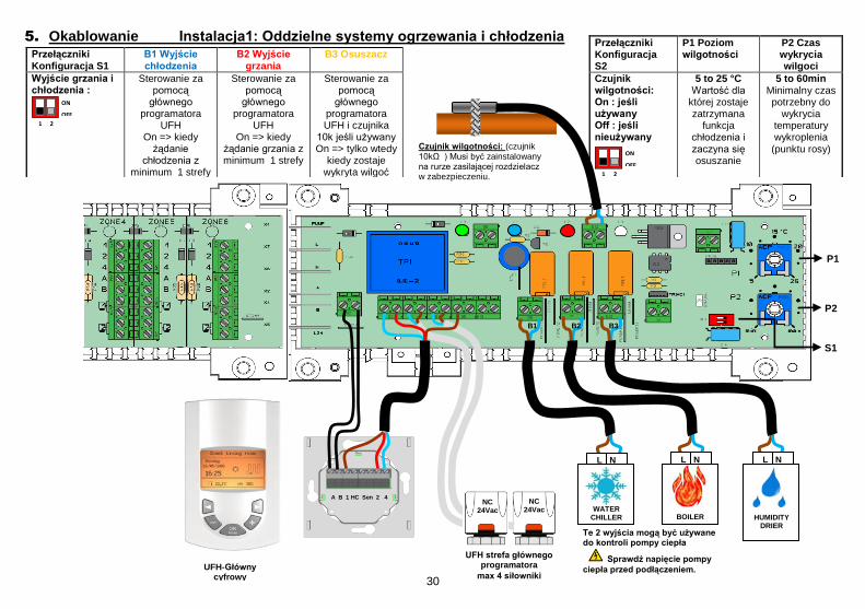
3. Possible combinations (7, 11, 13 zones)
4. LED indicator
LED 1: Green => System in standby
Orange => Pump indicator (minimum one demand from a zone)
Red Blinking => Sensor Error
LED 2: Blue => Cooling Mode indication Blue Blinking => Humidity drier is activated LED 3: Red => Heating Mode indication LED 4 to 6: => Not used
MASTER 6 ZONES + SLAVE 6 ZONES + H&C MODULE
MASTER 6 ZONES + SLAVE 4 ZONES + H&C MODULE
MASTER 6 ZONES + H&C MODULE

6
5. Wiring Installation1: Separates systems S2 DIP switch Configuration
P1 Humidity Level
P2 Humidity Detection
Time
Humidity sensor : On : if used Off : if not used ON
OFF
1 2
5 to 25 °C Setting level to stop the cooling output and start
the humidity drier.
5 to 60min Minimum time for humidity temperature
detection
S1 DIP switch
Configuration
B1 Cooling
Output
B2 Heating Output B3 Humidity
Drier
Heating and cooling output : ON
OFF
1 2
Managed by the UFH digital
programmer On => only
when cooling demand from minimum one
zone
Managed by the UFH digital programmer
On => only when heating demand
from minimum one zone
Managed by the UFH digital
programmer and the 10k sensor if
used On => only when
humidity is detected.
UFH digital main programmer zone
4 actuators max UFH-DIGITAL PROGRAMME
R
These 2 outputs can be used to control the heat pump
Check the voltage input of the
heat pump before connections.
S1
P1
P2
A B 1 HC Sen 2 4 NC
24Vac
B1 B2 B3
NC 24Vac
L N
BOILER
L N
HUMIDITY DRIER
Humidity sensor: (10k sensor) Must be mounted on the incoming water pipe of the manifold with precautions.
L N
WATER CHILLER

7
Heat & Cool Input: (Free contact) Open => The system will work in heat mode Closed => The system will work in Cooling mode
Check the heat pump output before connection.
6. Wiring Installation2: Reversible Heat pump (with external heat&cool signal)
DIP switch Configuration S1
B1 Cooling Output B2 Heating Output B3 Humidity Drier
Heating and cooling output : ON
OFF
1 2
Managed by the UFH digital
programmer in accordance with the heat pump signal.
On => only when cooling demand from minimum one zone
Managed by the UFH digital
programmer in accordance with the heat pump signal.
On => only when cooling demand from minimum one zone
Managed by the UFH digital
programmer and the 10k sensor if
used On => only when
humidity is detected.
UFH-DIGITAL
PROGRAMMER
Humidity sensor: (10k sensor) Must be mounted on the incoming water pipe of the manifold with precautions.
UFH digital main programmer zone
4 actuators max
DIP switch Configuration S2
P1 Humidity Level
P2 Humidity Detection Time
Humidity sensor : On : if used Off : if not used ON
OFF
1 2
5 to 25 °C
Setting level to stop the cooling output and start the humidity drier.
5 to 60min
Minimum time for humidity
temperature detection
A B 1 HC Sen 2 4 NC
24Vac
B1 B2 B3
P1
P2
NC 24Vac
NC 24Vac
NC 24Vac
S1
L N
HUMIDITY DRIER

8
UFH-DIGITAL
PROGRAMMER
Heat & Cool sensor: (10k sensor)
Must be mounted on the incoming water pipe of the manifold with precautions.
7. Wiring Installation3: Reversible Heat pump (without Heat&Cool information and control)
DIP switch Configuration S1 & S2
B1 Cooling Output
B2 Heating Output
B3 Humidity Drier
P1 Cooling level
P2 hysteresis
ON
OFF
1 2
Not used
Not used
Managed by
the UFH digital
programmer
5 to 25 °C
Minimum water temperature to switch the system in cooling
mode.
1 to 10°C
Hysteresis between Heat
& Cool commutation
UFH digital main programmer zone
4 actuators max
A B 1 HC Sen 2 4
NC 24Vac
B1 B2 B3
NC 24Vac
P1
P2
S1
L N
HUMIDITY DRIER

9
Manuel d’utilisation et d’installation
IMPORTANT!
- Avant de commencer les travaux, le monteur doit lire, comprendre et observer les présentes instructions de montage et de service. - Seul un spécialiste en la matière est autorisé à effectuer le montage, le réglage et la maintenance d’une régulation plancher type UFH. Un monteur en formation ne peut réaliser de travaux sur l'appareil que sous la surveillance d'un expert. La responsabilité du fabricant conformément aux dispositions légales s'applique uniquement dans le cas du respect des conditions précitées. - Veuillez observer l'ensemble des instructions de montage et de service lors de l'utilisation du programmateur de zones. Toute utilisation autre n'est pas conforme. Le fabricant ne répond pas des dommages occasionnés par une utilisation abusive de la régulation. Pour des raisons de sécurité, aucune transformation ou modification n'est admise. Seuls les ateliers de réparation désignés par le fabricant sont habilités à réparer la station solaire. - Le contenu de la livraison de l'appareil varie selon le modèle et l'équipement. Sous réserve de modifications techniques ! Il est recommandé que l’installateur et l’utilisateur prenne connaissance de l’intégralité de la notice, avant de procéder à l’installation du matériel.
APPLICATION
- Le thermostat été développé spécialement pour le contrôle et la gestion d’électrovannes montées sur les collecteurs de plancher (nourrisses). - Le thermostat est normalement utilisé en conjonction avec un «MASTER-UFH» avec ou sans module «CHAUD / FROID», ils permettront la connections de tous les composants électriques & hydraulique de votre installation. (Circulateur, électrovannes, thermostats) Le module de régulation a été étudié pour un fonctionnement dans un environnement résidentiel, bureaux ou en équipement industriel. Il est recommandé d’installer ce thermostat selon les règles de l’art le tout en respectant les législations en vigueur.
INSTRUCTION DE SECURITE
Veillez toujours à déconnecter l’alimentation avant le montage ou la manipulation! Toute installation ou raccordement électrique sur le module doit être réalisé dans des conditions de sécurité. Le module devra être raccordé et manipulé par du personnel qualifié. Veuillez respecter les législations de sécurité en vigueur, en particulier NF C15-100 (Normes d’installation ≤ 1000 VAC). Les boîtes de connexions ne sont pas étanches aux éclaboussures ou aux projections d’eau. Il doit donc être monté dans un endroit sec. Prêter une attention particulière lors du câblage, n’inter changez jamais les connections des sondes avec les connections de puissances (24VAC), ceci pourrait provoquer des dommages électriques voir la destruction des sondes ou la régulation.
Sujet à modification sans avis préalable!

10
1. Caractéristiques techniques
Température de fonctionnement
0°C - 50°C
Protection électrique Class I - IP20
Alimentation
Provient du Master UFH 24VAC Attention: Avant toute chose, veillez à remplacer le fusible présent sur le Master 24V par celui livré dans l’emballage. 5x20 3,15AT
Sorties : Chaud Froid Déshumidificateur
Relais 0,5 A 24V (L, N) Relais 0,5 A 24V (L, N) Relais 0,5 A 24V (L, N)
2. Description et Fonctionnement
- Le module Chaud&Froid combiné avec la centrale de programmation 24V est un module complémentaire au MASTER UFH 24V. - Ce module vous permettra de contrôler et de connecter tous les éléments de votre installation hydraulique réversible. (Pompe à chaleur ou élément séparés, Chaudière et climatiseur...) - Ce module vous permettra de rajouter une zone à votre installation cette zone est spécialement conçue pour la connexion de votre centrale de programmation). - Prêt pour 3 installations type: Installation1: Elément séparés ou pompe à chaleur réversible basique. Installation2: Pompe à chaleur réversible (manuelle ou automatique) Installation3: Pompe à chaleur réversible (sans information du mode de fonctionnement)

11
3. Combinaisons possible (7, 11, 13 zones)
4. Voyant d’état (LED)
LED 1: Vert => System en standby
Orange => Système en fonctionnement (au moins 1 zone est en demande)
Rouge clignotant => Erreur sonde
LED 2: Bleu => Mode Froid Bleu clignotant => Fonction déshumidification
(Sortie déshumidificateur activée)
LED 3: Rouge => Mode chaud
LED 4 to 6: => Non utilisées
MASTER 6 ZONES + SLAVE 6 ZONES + MODULE C&F
MASTER 6 ZONES + SLAVE 4 ZONES + MODULE C&F
MASTER 6 ZONES + MODULE C&F

12
5. Câblage Installation1: Eléments séparés ou pompe à chaleur réversible basique Interrupteur de configuration S2
P1 Réglage du seuil de
condensation
P2 Temps de détection
condensation
Sonde condensation: On : si utilisée Off : si non utilisée ON
OFF
1 2
5 à 25 °C Seuil de
déclenchement de la sortie
déshumidificateur et arrêt de la sortie Froid
5 to 60min Temps minimum pour enclencher
la fonction déshumidification
Interrupteur de configuration S1
B1 Sortie Froid B2 Sortie Chaud
B3 Sortie Déshumidificateur
Sortie Chaud et Froid : ON
OFF
1 2
Gérer par la centrale de
programmation On => seulement
si minimum 1 zone en demande
de Froid zone
Gérer par la centrale de
programmation On => seulement
si minimum 1 zone en
demande de chaud.
Gérer par la centrale de programmation et la sonde de condensation
si utilisée On => seulement si un risque de condensation
est détectée.
Electrovanne de la zone principale
4 électrovannes max CENTRALE de
PROGRAMMATION
(Zone principale)
Ces 2 sorties peuvent être utilisée pour une commande de pompe à chaleur (PAC réversible)
Vérifiez la compatibilité des tensions avant la connexion avec une PAC.
S1
P1
P2
A B 1 HC Sen 2 4 NC
24Vac
B1 B2 B3
NC 24Vac
L N
CHAUDIERE
L N
DESHUMI-
DIFICATEUR
Sonde de condensation: (NTC 10k) La sonde doit être montée avec précaution sur la tuyauterie d’alimentation du collecteur afin de bien capter la température de l’eau.
L N
CLIMATISEUR

13
6. Câblage Installation2: PAC Réversible (avec signal de sortie du mode Chaud / Froid) Interrupteur de configuration S1
B1 Sortie Froid B2 Sortie Chaud B3 Sortie Déshumidificateur
Sortie Chaud et Froid : ON
OFF
1 2
Gérée par la centrale de
programmation en accordance
avec le signal de la PAC
On => seulement si minimum 1 zone en demande de Froid.
Gérée par la centrale de
programmation en accordance avec le
signal de la PAC On => seulement si minimum 1 zone en demande de Chaud
Gérée par la centrale de
programmation et la sonde de
condensation si utilisée.
On => seulement si un risque de condensation
est détecté.
Interrupteur de configuration S2
P1 Réglage du seuil de
condensation
P2 Temps de détection
condensation
Sonde condensation: On : si utilisée Off : si non utilisée
ON
OFF
1 2
5 to 25 °C Seuil de
déclenchement de la sortie
déshumidificateur et arrêt de la sortie Froid.
5 to 60min
Temps minimum pour enclencher
la fonction déshumidification.
A B 1 HC Sen 2 4
NC 24Vac
B1 B2 B3
P1
P2
NC 24Vac
NC 24Vac
NC 24Vac
S1
L N
DESHUMIFI*-CATEUR
Sonde de condensation: (NTC 10k) La sonde doit être montée avec précaution sur la tuyauterie d’alimentation du collecteur afin de bien capter la température de l’eau.
CENTRALE de PROGRAMMATION
(Zone principale)
Electrovanne de la zone principale
4 électrovannes max
Entrée PAC: (Contact sec)
Circuit ouvert => Système en mode Froid Circuit fermé => Système en mode Chaud
Vérifiez la compatibilité de l’entrée avec le signal de sortie de la PAC. PAC.

14
CENTRALE de PROGRAMMATION
(Zone principale)
7. Wiring Installation3: Reversible Heat pump (without Heat&Cool information and control)
Interrupteur de Configuration S1 & S2
B1 Sortie Froid
B2 Sortie Chaud
B3 Sortie Déshumidificateur
P1 Seuil de détection du mode
Froid
P2 Hystérésis
Chaud/Froid
ON
OFF
1 2
Non utilisée
Non utilisée
Gérer par la centrale de programmation. On => seulement si
un risque de condensation est
détectée.
5 to 25 °C
Seuil d’enclenchement du
mode froid.
1 to 10°C
Hystérésis entre un basculement
de Chaud à Froid
A B 1 HC Sen 2 4
NC 24Vac
B1 B2 B3
NC 24Vac
P1
P2
S1
L N
DESHUMIDI-FICATEUR
Electrovanne de la
zone principale 4 électrovannes max
Sonde détection du mode froid: (NTC 10k) La sonde doit être montée avec précaution sur la tuyauterie d’alimentation du collecteur afin de bien capter la température de l’eau.

15
Installations- und Bedienungsanleitung
Wichtig!!
Bevor Sie mit der Installation beginnen, sollten sie sich die Installations- und Bedienungsanleitung sorgfältig durchlesen und unbedingt die nachfolgenden Punkte beachten: - Der Raumthermostat darf nur von Fachpersonal oder unter deren Aufsicht
installiert, angeschlossen und konfiguriert werden. Für Schäden die durch unsachgemäße Installation oder Montage entstehen kann keine Gewährleistung oder Haftung übernommen werden.
- Die Installations- und Bedienungshinweise für dieses Gerät sind zu beachten. Für Schäden durch nicht bestimmungs-gemäßen Betrieb, Eingriffe in die Elektronik oder Software oder falsche Handhabung kann keine Gewährleistung oder Haftung übernommen werden.
ANWENDUNG - Der Thermostat wurde für die Einzelraumregelung bzw. Ansteuerung
elektrothermischer Stellantriebe in wassergestützten Heizungs- und/oder Kühlungssystemen entwickelt.
- Der Anschluss aller elektrischen Komponenten in Verbindung mit dem Zentral Programmer & Thermostat sollte in Verbindung mit den entsprechenden Schaltleisten und Erweiterungsmodulen erfolgen.
SICHERHEITS HINWEISE Vor Beginn aller Installations- und Montagearbeiten die Netzspannung abschalten!!! - Stellen sie sicher das vor Beginn und während aller Installations- und
Montagearbeiten die Anlage spannungsfrei ist. Die Arbeiten dürfen nur durch Fachleute ausgeführt werden. Die Elektroinstallation muss den geltenden Richtlinien und Verordnungen entsprechen.
Kontrollieren sie vor der Inbetriebnahme den richtigen Anschluss des Reglers. Ein vertauschen der Anschlüsse kann zu einem Kurzschluss und zu einer Zerstörung des Reglers oder der angeschlossenen Geräte führen.

16
1. Technische Daten
Betriebstemperatur 0°C - 50°C
Schutzart und -klasse IP20 / Schutzklasse I
Betriebsspannung
Über Master Schaltleiste 24VAC Achtung: Vor Anschluss die in der Master Schaltleiste installierte Sicherung durch beigepackte Sicherung austauschen!!!!! 5x20 3,15AT
Ausgänge : Heizen Kühlen Trockner
Relais 0,5 A 24V (L, N) Relais 0,5 A 24V (L, N) Relais 0,5 A 24V (L, N)
2. Funktionsbeschreibung
- Das Heiz- und Kühl Modul 24 V ist ein Erweiterungsmodul für die Master
Schaltleiste 24 V. In Verbindung mit dem Zentral Programmer Thermostat wird die Regelung hierdurch um die Funktionsart Kühlen erweitert.
- Durch die Relaisausgänge können Wärmepumpe, Kälte- und Wärmeerzeuger, Trockner, etc. angesteuert werden
- Anschlussmöglichkeit des Zentral Programmer Thermostat - Anschlussmöglichkeit von 3 verschiedenen Heiz- und Kühl Systemen: Installation 1: Getrennte Wärme und Kälteerzeuger Installation 2: Wärmepumpe (Umschaltung extern) Installation 3: Wärmepumpe (Umschaltung über Sensor)

17
3. Possible combinations (7, 11, 13 zones)
4. LED Anzeige
LED 1: Grün => Standby
Orange => Leistungsanforderung (min. eine Zone hat geschaltet)
Rot blinkend => Fühler Fehler
LED 2: Blau => Kühlmodus ist aktiv Blau blinkend => Trocknerausgang ist aktiviert LED 3: Rot => Heizmodus ist aktiv LED 4 to 6: => nicht benutzt
MASTER 6 ZONEN + SLAVE 6 ZONEN + HEIZ- UND KÜHL MODUL
MASTER 6 ZONEN + SLAVE 4 ZONEN + HEIZ- UND KÜHL MODUL
MASTER 6 ZONEN + HEIZ- UND KÜHL MODUL

18
5. Verdrahtung Installation 1: Getrennte Wärme und Kälteerzeuger DIP switch Konfiguration S2
P1 Grenztemperatur
P2 Zeitsperre
Externer Fühler On : Fühler Off : kein Fühler ON
OFF
1 2
5 to 25 °C Bei
Unterschreitung wird der
Kühlausgang B1 aus und der
Trocknerausgang B3 eingeschaltet
5 to 60min Mindestzeit für
Grenztemperatur-unterschreitung. Erst nach Ablauf der Zeitsperre
werden die Ausgänge B1 und
B3 geschaltet
Stellantriebe für
Zentral Thermostat Zentral
Thermostat
Vor dem Anschluß bitte die Herstellerangaben des jeweiligen
Gerätes überprüfen!!!
S1
P1
P2
A B 1 HC Sen 2 4 NC
24Vac
B1 B2 B3
NC 24Vac
L N
Heizausgang
L N
Trockner
L N
Kühlausgang
DIP switch Konfiguration S1
B1 Kühlausgang
B2 Heizausgang
B3 Trockner
Heiz- und Kühlausgang: ON
OFF
1 2
Wird über Zentral Thermostat gesteuert
An: wenn bei min. einem Raumregler Kälteanforderung
besteht
Wird über Zentral Thermostat gesteuert
An: wenn bei min. einem Raumregler Wärmeanforderung
besteht
Wird über Zentral Thermostat und externen Fühler
(optional) gesteuert An: wenn Temp. am
externen Fühler unter Grenztemp. P1
und über Zeit P2.
Externer Temperatur Fühler zur Taupunktüberwachung (optional) Sensor muss temperaturschlüssig am Vorlauf des Heizungssystems angebracht sein!!

19
Potentialfreier Umschaltkontakt: Offen : Heizbetrieb Geschlossen : Kühlbetrieb
Kontakt muss spannungsfrei sein!!!!!
6. Verdrahtung Installation 2: Wärmepumpe (Umschaltung extern)
DIP switch Konfiguration S1
B1 Kühlausgang
B2 Heizausgang
B3 Trockner
Heiz- und Kühlausgang: ON
OFF
1 2
Wird über Zentral Thermostat gesteuert
An: wenn bei min. einem Raumregler Kälteanforderung
besteht
Wird über Zentral Thermostat gesteuert
An: wenn bei min. einem Raumregler Wärmeanforderung
besteht
Wird über Zentral Thermostat und externen Fühler
(optional) gesteuert An: wenn Temp. am
externen Fühler unter Grenztemp.
P1 und über Zeit P2
Zentral Thermostat
Stellantriebe für
Zentral Thermostat
DIP switch Konfiguration S2
P1 Grenztemperatur
P2 Zeitsperre
Externer Fühler : On : Fühler
Off : kein Fühler ON
OFF
1 2
5 to 25 °C Bei
Unterschreitung wird der
Kühlausgang B1 aus und der
Trocknerausgang B3 eingeschaltet
5 to 60min Mindestzeit für
Grenztemperatur-unterschreitung. Erst nach Ablauf der Zeitsperre
werden die Ausgänge B1 und
B3 geschaltet
A B 1 HC Sen 2 4 NC
24Vac
B1 B2 B3
P1
P2
NC 24Vac
NC 24Vac
NC 24Vac
S1
L N
Trockner
Externer Temperatur Fühler zur Taupunktüberwachung
(optional)
Sensor muss temperaturschlüssig am Vorlauf
des Heizungssystems angebracht sein!!

20
Zentral Thermostat
7. Verdrahtung Installation 3: Wärmepumpe (Umschaltung über Sensor)
DIP switch Konfiguration S1 & S2
B1 Kühlaus-gang
B2 Heizaus-gang
B3 Trockner
P1 Grenztemperatur
P2 Hysterese
ON
OFF
1 2
Nicht angeschlossen
Nicht angeschlossen
Wird über Zentral
Programmer Thermostat gesteuert
5 to 25 °C Bei
Unterschreitung wird das System
in den Kühlmodus geschaltet
1 to 10°C Hysterese bei
welcher Temperatur wieder in
Heizmodus umgeschaltet wird
Stellantriebe für
Zentral Thermostat
A B 1 HC Sen 2 4
NC 24Vac
B1 B2 B3
NC 24Vac
P1
P2
S1
L N
Trockner
Externer Temperatur Fühler zur Taupunktüberwachung (optional)
Sensor muss temperaturschlüssig am Vorlauf
des Heizungssystems angebracht sein!!

21
Installatie en bedieningshandleiding
BELANGRIJK! Alvorens de installatie uit te voeren moet de handleiding gelezen en begrepen worden door de installateur. - De Main zone digitale programmator moet geplaatst en onderhouden worden door een gecertificeerde installateur. Personeel die de installatie cursus niet hebben voltooid mogen deze slechts plaatsen onder supervisie van een gecertificeerd persoon. Indien het bovenvermelde nauwlettend werd uitgevoerd zal de fabrikant de goede werking garanderen. - Alle instructies die in deze installatie en gebruikshandleiding voorkomen dienen te worden gevolgd bij het gebruik van de programmator. Andere gebruiksapplicaties dan deze beschreven worden niet ondersteunt. De fabrikant kan niet verantwoordelijk worden gesteld voor ondeskundig gebruik van de programmator. Wijzigingen op de bestaande regelcomponenten worden niet aanvaard, onderhoud kan slechts gebeuren door een gecertificeerde installateur. - De functionaliteit van de programmator is afhankelijk van het model en toebehoren. De installatie brochure maakt integraal deel uit van het product. Toepassing - The Main zone digitale programmator is ontworpen voor het regelen van vloerverwarming installaties gebruikt voor verwarmen en koelen in samenspraak met onze UFH thermostaten. De temperatuur in elk lokaal wordt door een thermostaat geregeld door een actie uit te voeren op de thermische motor die zich op de verdeler bevindt. De regelaar wordt gebruikt samen met de “UFH-MASTER” connectie box,met of zonder verwarming-/koeling module,om alle elektrische componenten aan te sluiten zoals motoren, sturingen en thermostaten. - De regelaar is ontworpen om gebruikt te worden in residentiële woningen, burelen en industriële gebouwen. Kijk na of de huidige installatie compatibel is met de voorschriften om een goede werking te kunnen garanderen.
Veiligheidsmaatregelingen Sluit de spanning af alvorens de regelapparatuur aan te sluiten. - De installatie en bedrading moet spanningsloos worden uitgevoerd. De regelcomponenten mogen slechts aangesloten worden door bevoegd personeel. Volg de locale veiligheidsmaatregelingen. - De master en slave units zijn niet spatwaterdicht, gelieve ze in een droge omgeving te plaatsen. -Gelieve de verbindingen van de thermostaat en de 24 V nauwlettend te volgen en deze niet te verwisselen. Foutieve verbindingen kunnen permanente schade aan de componenten en of elektrocutie tot gevolg hebben.

22
1. Technische Kenmerken
Bedrijfstemperatuur 0°C - 50°C
Bescherming klasse Class I - IP20
Voedingsspanning Opgelet:
Komt van de UFH Master 24VAC Alvorens in bedrijf te plaatsen gelieve de zekering in de UFH Master te vervangen door de meegeleverde zekering 5x20 3,15AT
Uitgangen: Verwarming Koeling Ontvochtiger
Relais 0,5 A 24V (L, N) Relais 0,5 A 24V (L, N) Relais 0,5 A 24V (L, N)
2. Functies en beschrijving
- De combinatie van Verwarming & Koeling module 24V en de UFH digitale main zone programmator is een extensie die samenwerkt met de UFH MASTER 24V. - Deze module laat u toe de koeling en verwarming te sturen en te verbinden (Warmtepomp of ketel en externe koeler..) - Deze module beschikt over een supplementaire zone om de UFH main zone programmator aan te sluiten. - Mogelijkheid voor types installaties te sturen: Installatie 1: Gescheiden systeem of bijhorende warmtepomp Installatie 2: Omkeerbare warmtepomp (manueel of automatisch) Installatie 3: Omkeerbare warmtepomp (zonder status informatie)

23
3. Mogelijke combinaties (7, 11, 13 zones)
4. LED indicatie
LED 1: Groen => Systeem in standby modus
Orange => Pomp indicatie (minimum 1 zone in bedrijf)
Rood knipperend => Voeler defect
LED 2: Blauw => Koeling modus indicatie Blauw knipperend => Ontvochtiger in werking LED 3: Rood => Verwarming modus indicatie LED 4 tot 6: => Niet in gebruik
MASTER 6 ZONES + SLAVE 6 ZONES + H&C MODULE
MASTER 6 ZONES + SLAVE 4 ZONES + H&C MODULE
MASTER 6 ZONES + H&C MODULE

24
5. Bedrading Installatie 1: Gescheiden systeem
DIP switch Configuratie S2
P1 Limiet vochtigheid
P2 Vochtigheid Detectie tijd
Vochtigheidsvoeler On : gebruikt Off : niet gebruikt ON
OFF
1 2
5 to 25 °C Instelwaarde voor koeling stop en start ontvochtiger.
5 to 60min Minimum detectie
tijd voor de relatieve
vochtigheidsmeting
DIP switch Configuratie S1
B1 Koeling Uitgang
B2 Verwarming Uitgang
B3 Ontvochtiger
Verwarming & koeling uitgang: ON
OFF
1 2
Controle door de UFH digital programmator
On => koelingvraag
van minstens 1 zone
Controle door de UFH digital
programmator On => warmtevraag
van minstens 1 zone
Controle door de UFH digital
programmator en de externe voeler On => bij te hoge
relatieve vochtigheid.
UFH-DIGITAL PROGRAMME
R
S1
P1
P2
A B 1 HC Sen 2 4 NC
24Vac
B1 B2 B3
NC 24Vac
L N
Ketel
L N
Ontvochtige
Vochtigheidsvoeler: (10k voeler) Moet zorgvuldig op de aanvoerleiding van de verdeler geplaatst worden.
L N
Koeler
UFH digital main programmator zone
4 motoren maximum
Deze 2 uitgangen kunnen gebruikt worden voor de sturing van de warmtepomp
Gelieve de spanning te meten alvorens .het in bedrijfstellen

25
Open => Het systeem werk in verwarming modus Gesloten => Het systeem werkt in koeling modus Gelieve dit contact te testen alvorens aan te sluiten.
6. Bedrading Installatie2: Omkeerbare warmtepomp (met externe signalisatie)
DIP switch Configuratie S1
B1 Koeling Uitgang
B2 Verwarming Uitgang
B3 Ontvochtiger.
Verwarming & koeling uitgang: ON
OFF
1 2
Controle door de UFH digital
programmator in functie van het extern signaal.
On => koelingvraag van minstens 1
zone
Controle door de UFH digital
programmator in functie van het extern signaal.
On => warmtevraag van minstens 1
zone
Controle door de UFH digital
programmator en de externe voeler On => bij te hoge
relatieve vochtigheid
UFH-DIGITAL
PROGRAMMER
Vochtigheidsvoeler: (10k voeler) Moet zorgvuldig op de aanvoerleiding van de verdeler geplaatst worden.
UFH digital main programmator zone
4 motoren maximum
DIP switch Configuratie S2
P1 Limiet vochtigheid
P2 Vochtigheid Detectie tijd
Vochtigheidsvoeler On : gebruikt Off : niet gebruikt ON
OFF
1 2
5 to 25 °C
Instelwaarde voor koeling stop en start ontvochtiger.
5 to 60min
Minimum detectie tijd voor de
relatieve vochtigheidsmeting
A B 1 HC Sen 2 4 NC
24Vac
B1 B2 B3
P1
P2
NC 24Vac
NC 24Vac
NC 24Vac
S1
L N
Ontvochtige

26
UFH-DIGITAL
PROGRAMMER
Verwarming & Koeling (10k voeler) Moet zorgvuldig op de aanvoerleiding van de verdeler geplaatst worden
7. Bedrading Installatie 3: Omkeerbare warmtepomp (zonder status terugkoppeling)
DIP switch Configuratie S1 & S2
B1 Koeling Uitgang
B2 Verwarming
Uitgang
B3 Ontvochtiger
P1 Koeling detectie
P2 Hysteresis
ON
OFF
1 2
Niet gebruikt
Niet gebruikt
Controle door
de UFH digital
programmator
5 to 25 °C
Minimum water temperatuur als detective koeling
modus.
1 to 10°C
Hysteresis tussen
verwarming en koeling modus
UFH digital main programmator zone
4 motoren max
A B 1 HC Sen 2 4
NC 24Vac
B1 B2 B3
NC 24Vac
P1
P2
S1
L N
Ontvochtige

27
Instrukcja Instalacji i Użytkowania (uruchomienia)
Uwaga!
Przed rozpoczęciem pracy instalator powinien dokładnie przeczytać „Instrukcję Instalacji i Użytkowania” i upewnić się, że wszystkie zawarte w niej informacje są dla niego zrozumiałe. - Termostat glowny powinien byc zamontowany, uruchomiony i serwisowany wylacznie przez wyspecjalizowany personel Osoba bez odpowiednich uprawnień może instalować/uruchamiać termostat tylko pod nadzorem doświadczonego pracownika. - Wszystkie wytyczne zawarte w „Instrukcji Instalacji i Użytkowania” powinny być przestrzegane podczas pracy z termostatem. Producent nie jest odpowiedzialny za nieprawidłowe używanie termostatu. Wszelkie modyfikacje i naprawy urządzenia są zabronione ze względów bezpieczeństwa. Serwisowanie urządzeń powinno odbywać się wyłącznie poprzez punkty serwisowe wskazane przez producenta. - Funkcjonalność urządzenia jest zależna od odpowiedniego modelu i wyposażenia. Instrukcja jest nieodłączną częścią każdego zestawu. Zastosowanie - Termostat główny został opracowany aby kontrolować i sterować działaniem wszystkich instalacji wodnego ogrzewania i chłodzenia płaszczyznowego wyposażonych w lokalne termostaty pokojowe. Temperatura w każdym pokoju jest regulowana poprzez siłowniki znajdujące się na rozdzielaczu. - Termostat jest zwykle używany we współpracy z listwą automatyki z/bez modułu „ogrzewanie/chłodzenie” aby połączyć wszelkie elektryczne i hydrauliczne elementy instalacji jak pompa obiegowa, siłowniki itp. - Termostaty zostały zaprojektowane z myślą o zastosowaniu ich w domach/mieszkaniach, biurach i budynkach przemysłowych Przed podłączeniem instalacji zweryfikuj czy odpowiada ona obowiązującym przepisom.
Instrukcje bezpieczeństwa
Przed rozpoczęciem podłączania termostatu odłącz zasilanie prądu! - Wszystkie prace montażowe związane z termostatem muszą się odbywać przy odłączonym zasilaniu prądu. Urządzenie powinno być podłączone i uruchomione wyłącznie przez uprawnione osoby. Upewnij się aby instalacja została przeprowadzona zgodnie z przepisami dotyczącymi bezpieczeństwa - Listwy Automatyki nie są wodoodporne. Z tego względu należy je montować w suchych miejscach. - Nie wolno zmieniać podłączeń termostatu ani napięcia 24V pod żadnym względem. Zmiany takie mogą skutkować porażeniem prądem, zniszczeniem urządzenia i podłączonych do niego czujników bądź innych urządzeń

28
1. Charakterystyka techniczna
Temperatura pracy 0°C - 50°C
Stopień ochrony Klasa I - IP20
Zasilanie Ważne:
Z listwy UFH Master 24VAC Przed podłączeniem modułu wymień bezpiecznik zamontowany na listwie UFH Master na nowy 5x20 3,15AT / zwłoczny /
Wyjścia: Ogrzewanie Chłodzenie Osuszacz
Przekaźnik 0,5 A 24V (L, N) Przekaźnik 0,5 A 24V (L, N) Przekaźnik 0,5 A 24V (L, N)
2. Funkcje i Opis
- Moduł Ogrzewanie&Chłodzenie 24V w połączeniu z termostatem nadrzędnym UFH jest dodatkowym modułem, który pracuje z listwą UFH MASTER 24V. - moduł ten pozwala połączyć I kontrolować wszystkie urządzenia grzewczo-chłodnicze twojego domu (pompa ciepła lub system z kotłem i oddzielnym źródłem chłodu...) - moduł jest także wyposażony w dodatkową strefę do podłączenia termostatu nadrzędnego UFH - Przeznaczony dla 3 typów instalacji ogrzewania i chłodzenia: Instalacja1: Oddzielne systemy ogrzewania i chłodzenia lub pompa ciepła Instalacja2: Pompa ciepła z funkcją chłodzenia (z możliwością sterowania pompą poprzez Moduł Ogrzewanie & Chłodzenie) Instalacja3: Pompa ciepła z funkcją chłodzenia (bez możliwości sterowania pompą poprzez Moduł Ogrzewanie & Chłodzenie)

29
3. Możliwe kombinacje (7, 11, 13 stref - Termostatów)
4. Dioda LED
LED 1: Zielony => System w stanie gotowości
Pomarańczowy => Pompa włączona (minimum jedno żądanie ze strefy)
Czerwony migający => Błąd czujnika
LED 2: Niebieski => Tryb chłodzenia włączony Niebieski migający => Osuszacz jest aktywny LED 3: Czerwony => Tryb grzania włączony LED 4 to 6: => Nieużywane
MASTER 6 STREF + SLAVE 4 STREFY + MODUŁ
Ogrzewanie&Chłodzenie
MASTER 6 STREF + SLAVE 6 STREF + MODUŁ
Ogrzewanie&Chłodzenie
MASTER 6 STREF + MODUŁ Ogrzewanie&Chłodzenie
30
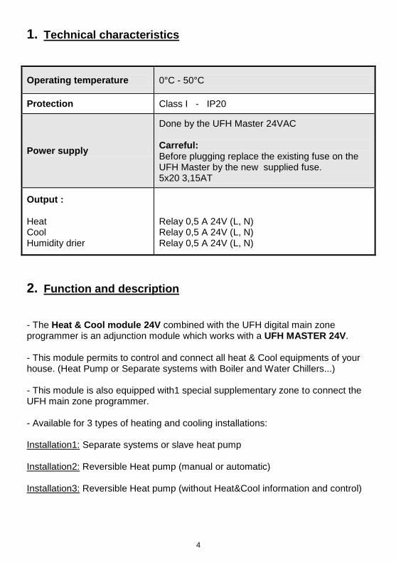
5. Okablowanie Instalacja1: Oddzielne systemy ogrzewania i chłodzenia Przełączniki Konfiguracja S2
P1 Poziom wilgotności
P2 Czas wykrycia wilgoci
Czujnik wilgotności: On : jeśli używany Off : jeśli nieużywany
ON
OFF
1 2
5 to 25 °C Wartość dla
której zostaje zatrzymana
funkcja chłodzenia i zaczyna się osuszanie
5 to 60min Minimalny czas potrzebny do
wykrycia temperatury wykroplenia (punktu rosy)
Przełączniki Konfiguracja S1
B1 Wyjście chłodzenia
B2 Wyjście grzania
B3 Osuszacz
Wyjście grzania i chłodzenia : ON
OFF
1 2
Sterowanie za pomocą
głównego programatora
UFH On => kiedy
żądanie chłodzenia z
minimum 1 strefy
Sterowanie za pomocą
głównego programatora
UFH On => kiedy
żądanie grzania z minimum 1 strefy
Sterowanie za pomocą
głównego programatora UFH i czujnika
10k jeśli używany On => tylko wtedy
kiedy zostaje wykryta wilgoć
UFH strefa głównego programatora
max 4 siłowniki UFH-Główny
cyfrowy programator
Te 2 wyjścia mogą być używane do kontroli pompy ciepła
Sprawdź napięcie pompy
ciepła przed podłączeniem.
S1
P1
P2
A B 1 HC Sen 2 4 NC
24Vac
B1 B2 B3
NC 24Vac
L N
BOILER
L N
HUMIDITY DRIER
Czujnik wilgotności: (czujnik 10kΩ ) Musi być zainstalowany na rurze zasilającej rozdzielacz w zabezpieczeniu.
L N
WATER CHILLER

31
Wejście Ogrzewanie&Chłodzenie: (Bezpośrednie podłączenie) Otwarty => System będzie pracował w trybie ogrzewania Zamknięty => System będzie pracował w trybie chłodzenia
Sprawdź wyjście pompy ciepła przed podłączeniem.
6. Okablowanie Instalacja2: Pompa ciepła z funkcją chłodzenia (z możliwością sterowania pompą)
Przełączniki Konfiguracja S1
B1 Wyjście chłodzenia
B2 Wyjście grzania B3 Osuszacz
Heating and Wyjście chłodzenia : ON
OFF
1 2
Sterowanie za pomocą głównego programatora
UFH zgodnie z sygnałem z pompy
ciepła. On => kiedy żądanie
chłodzenia z minimum 1 strefy
Sterowanie za pomocą głównego programatora UFH
zgodnie z sygnałem z pompy ciepła.
On => kiedy żądanie chłodzenia z
minimum 1 strefy
Sterowanie za pomocą głównego programatora UFH i czujnika 10k jeśli
używany On => tylko wtedy
kiedy zostaje wykryta wilgoć
UFH-Główny cyfrowy
programator
Czujnik wilgotności: (czujnik 10kΩ) Musi być zainstalowany na rurze zasilającej rozdzielacz w zabezpieczeniu.
UFH strefa głównego programatora
max 4 siłowniki
Przełączniki Konfiguracja S2
P1 Poziom wilgotności
P2 Czas wykrycia wilgoci
Czujnik wilgotności: On : jeśli używany Off : jeśli nieużywany ON
OFF
1 2
5 to 25 °C Wartość dla której zostaje zatrzymana funkcja chłodzenia i zaczyna się osuszanie
5 to 60min Minimalny czas potrzebny do
wykrycia temperatury wykroplenia (punktu rosy)
A B 1 HC Sen 2 4 NC
24Vac
B1 B2 B3
P1
P2
NC 24Vac
NC 24Vac
NC 24Vac
S1
L N
OSUSZACZ

32
UFH-Główny cyfrowy
programator
Czujnik wilgotności: (czujnik 10kΩ)
Musi być zainstalowany na rurze zasilającej rozdzielacz w zabezpieczeniu.
7. Okablowanie Instalacja3: Pompa ciepła z funkcją chłodzenia (bez możliwości sterowania pompą)
Przełączniki Konfiguracja S1 & S2
B1 Wyjście chłodzenia
B2 Wyjście grzania
B3 Osuszacz
P1 Poziom chłodz.
P2 Histereza
ON
OFF
1 2
Nieużywany
Nieużywany
Sterowanie za pomocą głównego
programatora UFH
5 to 25 °C Minimalna
temperatura wody aby można przełączyć
system w tryb chłodzenia.
1 to 10°C Histereza
przełączenia pomiędzy trybem
ogrzewania i chłodzenia
UFH strefa głównego programatora
max 4 siłowniki
A B 1 HC Sen 2 4
NC 24Vac
B1 B2 B3
NC 24Vac
P1
P2
S1
L N
OSUSZACZ

33
Manual pentru Instalare şi Utilizare
IMPORTANT!
Înaintea începerii montării, instalatorul trebuie să citească cu atenţie acest Manual pentru Instalare şi Utilizare şi să se asigure că toate instrucţiunile conţinute în acesta sunt înţelese şi respectate. - Termostatul trebuie montat, utilizat şi întreţinut numai de către personal calificat. Personalul aflat în curs de formare are voie doar să manevreze produsul sub supravegherea unui instalator experimentat. Sub rezerva respectării termenilor de mai sus, producătorul îşi asumă răspunderea pentru echipament în conformitate cu prevederile legale. - Toate instrucţiunile din acest Manual pentru Instalare şi Utilizare trebuie respectate când se lucrează cu regulatorul. Orice altă aplicare nu va fi conformă cu reglementările. Producătorul nu răspunde în cazul utilizării incompetente a termostatului . Nici o modificare sau amendament nu este permis din motive de siguranţă. Întreţinerea poate fi asigurată doar de centre service autorizate de producător. - Funcţionalitatea Termostatului depinde de model şi echipament. Această broşură de instalare face parte din produs şi trebuie obţinută. APLICARE - Termostatul este proiectat să controleze şi să administreze toate instalaţiile de încălzire şi răcire sub pardoseală echipate cu un termostat din gama UFH. Temperatura din fiecare încăpere este controlată cu ajutorul dispozitivelor de comandă montate pe conducte. - Regulatorul este utilizat în mod normal împreună cu o cutie de conexiuni completă “UFH-MASTER” cu sau fără “ modul de încălzire & răcire” pentru conectarea tuturor componentelor electrice şi hidraulice ale instalaţiei, ca de exemplu pompă, dispozitive de comandă ... - Regulatoarele au fost proiectate pentru utilizare în încăperi, spaţii cu birouri şi spaţii industriale. Verificaţi dacă instalarea respectă reglementările existente înaintea asigurării utilizării corecte a instalaţiei.
INSTRUCŢIUNI PENTRU SIGURANŢĂ
Înaintea începerii montării, întrerupeţi alimentarea cu curent! - Toate lucrările de instalare şi conectare aferente regulatorului trebuie efectuate doar când nu trece curentul prin el. - Cutiile de conexiuni nu sunt nici protejate contra stropirii nici protejate contra picăturilor de apă. De aceea, ele trebuie montate într-un loc uscat. - Nu schimbaţi niciodată între ele conexiunile termostatelor şi conexiunile de 24V! Interschimbarea acestor conexiuni poate duce la accidente electrice grave sau la distrugerea aparatului, a senzorilor conectaţi şi a altor aparate.

34
1. Caracteristici tehnice
Temperatura de funcţionare 0°C - 50°C
Protecţie Clasa I - IP20
Alimentare Atenţie:
Prin UFH Master 24VAC Înaintea conectării la curent, înlocuiţi siguranţa existentă pe UFH Master cu siguranţa nouă furnizată .5x20 3,15AT
Randamente : Încălzire Răcire Dezumidificator
Releu 0,5 A 24V (L, N) Releu 0,5 A 24V (L, N) Releu 0,5 A 24V (L, N)
2. Funcţie şi descriere
- Modulul Încălzire & Răcire 24V combinat cu programatorul zonal principal digital UFH este un modul complementar care funcţionează cu un UFH MASTER 24V. - Acest modul permite controlul şi conectarea tuturor instalaţiilor de încălzire şi răcire din casa dvs. (Pompă de căldură sau sisteme separate cu boiler şi răcitoare de apă...) - Acest modul este de asemenea prevăzut cu 1 zonă suplimentară specială pentru conectarea programatorului zonal principal. - Disponibil pentru 3 tipuri de instalaţii de încălzire şi răcire: Instalaţia 1: Sisteme separate sau pompă de căldură secundară Instalaţia 2: Pompă de căldură reversibilă (manuală sau automată) Instalaţia 3: Pompă de căldură (fără informaţii şi comandă Încălzire şi Răcire)
35
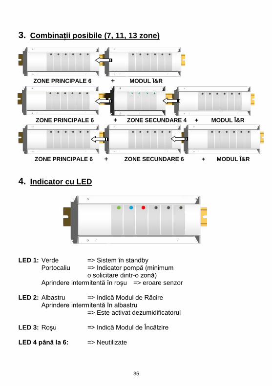
3. Combinaţii posibile (7, 11, 13 zone)
4. Indicator cu LED
LED 1: Verde => Sistem în standby
Portocaliu => Indicator pompă (minimum o solicitare dintr-o zonă)
Aprindere intermitentă în roşu => eroare senzor
LED 2: Albastru => Indică Modul de Răcire Aprindere intermitentă în albastru
=> Este activat dezumidificatorul LED 3: Roşu => Indică Modul de Încălzire LED 4 până la 6: => Neutilizate
ZONE PRINCIPALE 6 + ZONE SECUNDARE 6 + MODUL Î&R
ZONE PRINCIPALE 6 + ZONE SECUNDARE 4 + MODUL Î&R
ZONE PRINCIPALE 6 + MODUL Î&R

36
5. Conexiuni Instalaţia1: Sisteme separate Comutator DIP Configuraţie S2
Comutator DIP Configuraţie S2
Timp de detectare a
umidităţii P2
Senzor de umiditate : On : dacă se foloseşte Off : dacă nu se foloseşte
ON
OFF
1 2
5 până la 25 °C Nivel de setare pentru oprirea
puterii de răcire şi pornirea
dezumidificatorului.
5 până la 60min
Timp maxim pentru
detectarea temperaturii de
umiditate
Comutator DIP Configuraţia S1
Randament la răcire B1
Randament la încălzire B2
Dezumidificator B3
Randament la răcire şi încălzire : ON
OFF
1 2
Controlat de programator digital UFH On => doar
când există o cerere de răcire
din minim o zonă
Controlat de programator digital
UFH On => doar când există o cerere de
încălzire din minim o zonă
Controlat de programator digital UFH
şi de senzorul 10 k, după caz
On => doar când se depistează
umiditate.
UFH programator zonal prinicpal digital
cu max 4 disp. de acţionare
UFH-PROGRAMATOR DIGITAL
Aceste 2 ieşiri pot fi folosite pentru comanda pompei de căldură
Verificaţi tensiunea pompei de
căldură înaintea efectuării conexiunilor.
S1
P1
P2
A B 1 HC Sen 2 4 NC
24Vac
B1 B2 B3
NC 24Vac
L N
BOILER
L N
DEZUMIDIFICATOR
Senzor de umiditate: (senzor 10k)
Trebuie montat cu precauţie pe conducta de alimentare..
L N
RĂCITOR APĂ

37
Randament Încălzire & Răcire: (Contact liber) Open => Sistemul va funţciona pe încălzire Closed => Sistemul va funţciona pe răcire
Verificaţi puterea pompei de căldură înaintea conectării.
6. Conexiuni Instalaţia 2: Pompa de căldură reversibilă (cu semnal extern încălzire & răcire)
Comutator DIP Configuraţia S1
Randament la răcire B1
Randament la încălzire B2
Dezumidificator B3
Randament la răcire şi încălzire: ON
OFF
1 2
Controlat de programator digital
UFH conform semnalului pompei
de căldură On => doar când există o cerere de răcire din minim o
zonă
Controlat de programator digital
UFH conform semnalului pompei
de căldură On => doar când există o cerere de
încălzire din minim o zonă
Controlat de programator digital UFH
şi de senzorul 10 k, după caz
On => doar când se depistează
umiditate.
UFH-PROGRAMATOR DIGITAL
Senzor de umiditate: (senzor 10k)
Trebuie montat cu precauţie pe conducta de alimentare.
UFH programator zonal prinicpal digital cu max
4 disp. de acţionare
Comutator DIP Configuraţie S2
Nivel umiditate P1
Timp de detectare a
umidităţii P2
Senzor de umiditate : On : dacă se foloseşte Off : dacă nu se foloseşte
ON
OFF
1 2
5 până la 25 °C Nivel de setare pentru oprirea
puterii de răcire şi pornirea
dezumidificatorului.
5 până la 60min Timp maxim
pentru detectarea
temperaturii de umiditate
A B 1 HC Sen 2 4 NC
24Vac
B1 B2 B3
P1
P2
NC 24Vac
NC 24Vac
NC 24Vac
S1
L N
DEZUMIDIFICATOR

38
UFH-PROGRAMATOR
DIGITAL
Senzor de încălzire & răcire: (senzor 10k) Trebuie montat cu precauţie pe conducta de alimentare.
7. Conexiuni Instalaţia 3: Pompa de căldură reversibilă (fără informaţii şi comandă încălzire & răcire)
Comutator DIP Configuraţie S1 & S2
Randament la răcire B1
Randament la încălzire B2
Dezumidificator B3
Nivel de răcire P1 Histerezis P2
ON
OFF
1 2
Neutilizat
Neutilizat
Controlat de programator digital UFH
5 până la 25 °C Temperatura minimă a apei
pentru a comuta sistemul pe modul
răcire.
1 până la 10°C Histerezis între
comutare Încălzire & Răcire
UFH programator zonal prinicpal digital cu max 4 disp. de acţionare
A B 1 HC Sen 2 4
NC 24Vac
B1 B2 B3
NC 24Vac
P1
P2
S1
L N
DEZUMIDIFICATOR

39

40
Rettig Heating Sp. z o.o.
ul. Przemysłowa, 44-203 Rybnik, Poland Biuro Handlowe ul. Rotmistrza Pileckiego 91, 02-781 Warszawa, Poland Tel: +48 22 643 25 20 Fax: +48 22 643 99 95 [email protected] / www.purmo.pl
Rettig Belgium NV
Vogelsancklaan 250 B-3520 Zonhoven Tel: +49 5324 808-0 Fax: +49 5324 808-999 [email protected] / www.radson.com
Purmo DiaNorm Wärme AG
Lierestraße 68 38690 Vienenburg Germany Tel: +49 5324 808-0 Fax: +49 5324 808-999 [email protected] / www.purmo.de
PPLIMP06690 Aa