hd color camera - pro.sony · choosing devices, please contact your sony dealer or a sony service...
TRANSCRIPT
HD Color Camera
Operating InstructionsBefore operating the unit, please read this manual thoroughly and retain it for future reference.
HXC-D70
4-291-685-11 (2)
© 2011 Sony Corporation

2
Owner’s Record
The model and serial numbers are located at the top.Record these numbers in the spaces provided below. Refer to them whenever you call upon your Sony dealer regarding this product.
Model No. Serial No.
To reduce the risk of fire or electric shock, do not expose this apparatus to rain or moisture.
To avoid electrical shock, do not open the cabinet. Refer servicing to qualified personnel only.
For the customers in the U.S.A.This equipment has been tested and found to comply with the limits for a Class A digital device, pursuant to Part 15 of the FCC Rules. These limits are designed to provide reasonable protection against harmful interference when the equipment is operated in a commercial environment. This equipment generates, uses, and can radiate radio frequency energy and, if not installed and used in accordance with the instruction manual, may cause harmful interference to radio communications. Operation of this equipment in a residential area is likely to cause harmful interference in which case the user will be required to correct the interference at his own expense.
You are cautioned that any changes or modifications not expressly approved in this manual could void your authority to operate this equipment.
All interface cables used to connect peripherals must be shielded in order to comply with the limits for a digital device pursuant to Subpart B of Part 15 of FCC Rules.
This device complies with Part 15 of the FCC Rules. Operation is subject to the following two conditions: (1) this device may not cause harmful interference, and (2) this device must accept any interference received, including interference that may cause undesired operation.
For the customers in CanadaThis Class A digital apparatus complies with Canadian ICES-003.
For the customers in EuropeThis product with the CE marking complies with the EMC Directive issued by the Commission of the European Community.Compliance with this directive implies conformity to the following European standards:• EN55103-1: Electromagnetic Interference(Emission)• EN55103-2: Electromagnetic Susceptibility(Immunity)This product is intended for use in the following Electromagnetic Environments: E1 (residential), E2 (commercial and light industrial), E3 (urban outdoors), E4 (controlled EMC environment, ex. TV studio).
For the customers in EuropeThe manufacturer of this product is Sony Corporation, 1-7-1 Konan, Minato-ku, Tokyo, Japan.The Authorized Representative for EMC and product safety is Sony Deutschland GmbH, Hedelfinger Strasse 61, 70327 Stuttgart, Germany. For any service or guarantee matters please refer to the addresses given in separate service or guarantee documents.
For the State of California, USA onlyPerchlorate Material - special handling may apply, Seewww.dtsc.ca.gov/hazardouswaste/perchloratePerchlorate Material : Lithium battery contains perchlorate.
For the customers in Taiwan only
WARNING

Table of Contents
Chapter 1 Overview
Product Configurations............................................. 5
Features...................................................................... 6System Configuration.......................................................7
Standalone operation example ......................................7System operation example (with the HXCU-D70 Camera
Control Unit) ...............................................................8System operation example (with the CCU-D50/D50P
Camera Control Unit)..................................................8
Locations and Functions of Parts and Controls..... 9Power Supply ...................................................................9Accessory Attachments..................................................10Operating and Connectors Section ................................11Auto Focus Lens (Supplied with HXC-D70K).................15Viewfinder (supplied with HXC-D70K/D70L) ..................16
Viewfinder Screen Display...................................... 17
Chapter 2 Preparations
Connecting a Camera Control Unit (CCU)............. 19To use the cable clamp belt ...........................................19
Standalone Operation ............................................. 20Removing the Rear Cover..............................................20Using AC Power (via the DC IN connector) ...................20Using AC Power (with AC adaptor) ................................20Using a Battery Pack......................................................20
Attaching the Viewfinder......................................... 22Attaching the Supplied Viewfinder .................................22Adjusting the Viewfinder Position...................................22Adjusting the Viewfinder Angle ......................................23Lifting Up the Viewfinder Barrel and Eyepiece...............23Adjusting the Viewfinder Focus and Screen ..................24Attaching an Optional Viewfinder ...................................25
Setting the Area of Use ........................................... 27When using the camera for the first time .......................27To set the area of use ....................................................27
Setting the Date/Time of the Internal Clock .......... 28
Mounting and Adjusting the Lens.......................... 29Adjusting the Flange Focal Length.................................30
Preparing the Audio Input System......................... 31Connecting a Microphone to the AUDIO 1 IN Connector
....................................................................................31Connecting a Microphone to the AUDIO 2 IN Connector
....................................................................................31
Attaching a UHF Portable Tuner (for a UHF Wireless Microphone System) .................................................. 33
Mounting the Camera to a Tripod ..........................33
Using the Shoulder Strap (Optional)......................34
Adjusting the Shoulder Pad Position ....................35
Chapter 3 Shooting
Basic Procedure for Shooting ................................36
Adjustments and Settings ......................................37Changing the Video Format........................................... 37Adjusting the Black Balance and the White Balance ..... 37Setting the Electronic Shutter ........................................ 38Changing the Reference Value for Automatic Iris
Adjustment ................................................................. 39Zooming......................................................................... 39Adjusting the Focus ....................................................... 40Setting the Camera Outputs .......................................... 42Adjusting the Audio Level .............................................. 42Using the flash band compensation function ................. 43Using the digital extender function................................. 43
Chapter 4 Menu and Detailed Settings
Setup Menu Organization and Levels....................44Setup Menu Organization .............................................. 44
Basic Menu Operations...........................................48Displaying Menu Pages ................................................. 49Setting the Menu............................................................ 49Editing the USER Menu................................................. 51
Menu List ..................................................................54OPERATION Menu........................................................ 54PAINT Menu .................................................................. 59MAINTENANCE Menu................................................... 63FILE Menu ..................................................................... 69DIAGNOSIS Menu......................................................... 71
Chapter 5 Maintenance
Testing the camera ..................................................72
Maintenance .............................................................72Cleaning the Viewfinder................................................. 72Note about the Battery Terminal.................................... 72
Error Messages........................................................73
Table of Contents 3
4
Appendix
Important Notes on Operation................................ 74
Using a “Memory Stick Duo”.................................. 75
Exchanging the Battery of the Internal Clock....... 76
Specifications .......................................................... 77
Pin assignment ........................................................ 79
Table of Contents
hapter
Chapter 1
1
COverviewOverview
Product Configurations
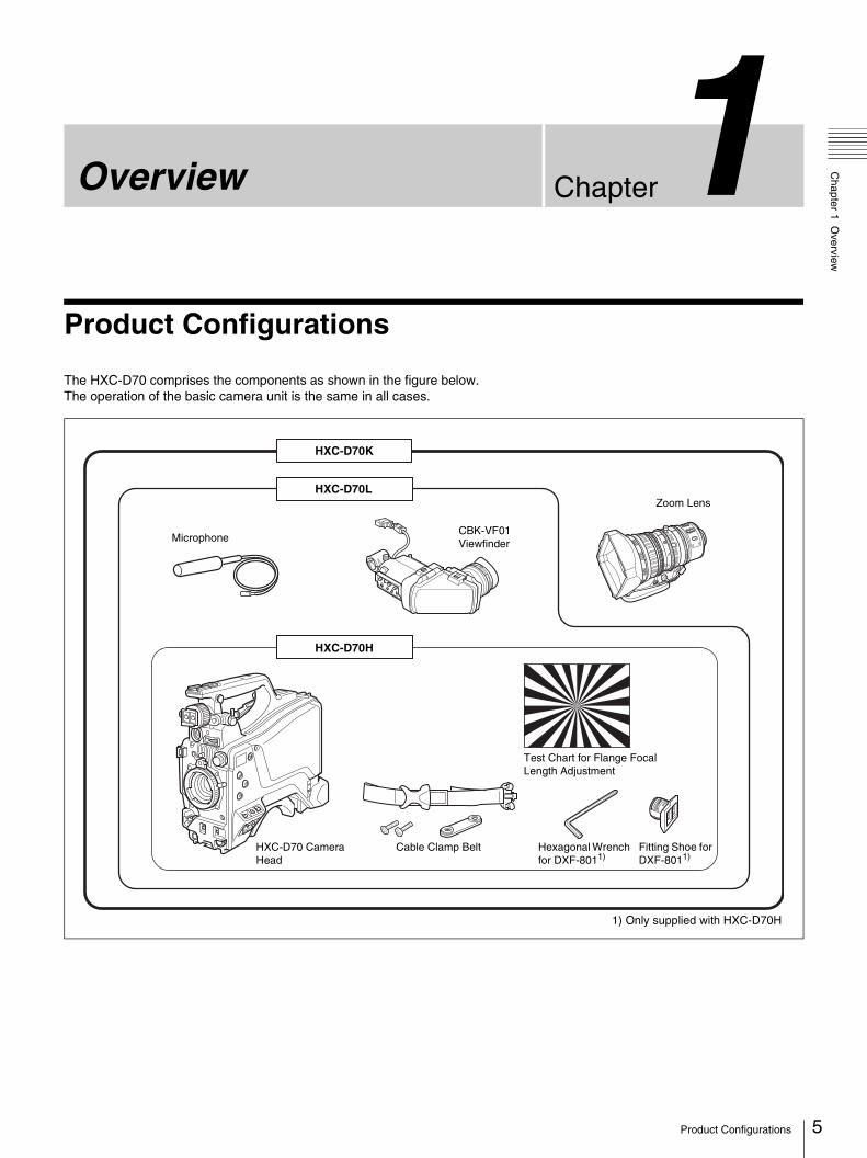
The HXC-D70 comprises the components as shown in the figure below. The operation of the basic camera unit is the same in all cases.
Microphone
HXC-D70K
HXC-D70L
CBK-VF01 Viewfinder
Zoom Lens
HXC-D70 Camera Head
HXC-D70H
Test Chart for Flange Focal Length Adjustment
Cable Clamp Belt Fitting Shoe for DXF-8011)
Hexagonal Wrench for DXF-8011)
1) Only supplied with HXC-D70H
5Product Configurations

6
Chapter 1 O
verview
Features
High picture quality and high performanceThe HXC-D70 is an HD color video camera equipped with three-chip 2/3-type “Exmor” CMOS image sensors. The approximately 2.07 million effective pixels image sensor technology for full HD resolution (1920 × 1080) and newly developed digital processing circuit enable the capture of very high-quality images, with a sensitivity of F12 (59.94i) / F13 (50i) and an SN ratio of 56 dB (w/o Noise Suppression (NS) mode).High-resolution pictures can be transmitted between the camera and camera control Unit (CCU) using Sony-developed digital transmission technology via multi-core cable.
Multiple formatsThe camera supports 1080/59.94i, 720/59.94P, 1080/50i, and 720/50P formats. With its wide-range down-converter, the camera also enables output of high-quality SD signals (525i/625i) from the camera and the connected CCU.
Using the HXCU-D70 and CCU-D50/D50P camera control units (CCU)The camera is compatible with the HXCU-D70 for HD/SD signal output, and CCU-D50/D50P for SD signal output. With HXCU-D70, HD/SD simultaneous output can be provided from both the camera and CCU.
Newly designed integrated unitThe camera comes with stylish and sophisticated appearance. It provides easy-to-use design for setting up a system with multi-core cables or for shooting with batteries on your shoulder. The CCZ-A connector on the camera enables you to connect it to the CCU using a single Sony multi-core cable. The interface follows the original design with more user-friendly features.
Various picture adjustment functions
Selection of multiple gamma tablesSeven types of standard and 4 types of hypergamma tables are featured. The hypergamma values enable cinema-like image creations with wide dynamic range, which are different from those achieved with conventional video gamma.
Knee saturationChange in hue and decrease in saturation that occur in highlighted areas can be compensated. This enables reproduction of natural skin tones under strong lighting.
Low key saturationSaturation in low-key zones can be compensated.
Skin-tone detailThis function allows control (emphasis or suppression) of the detail level for just a certain hue or saturation area in the image, such as skin tones.
Auto focusThe 2/3-type auto focus lens (supplied with HXC-D70K) ensures high-quality shooting in all situations from wide angle to telephoto. Using the HXC-D70 HD Color Camera enables auto-focusing, which is especially useful for technically demanding HD shooting.
Position-adjustable shoulder padThe position of the shoulder pad can be adjusted for stable shooting according to the build of the camera operator, the type of lens in use, or the shooting style. A low-repulsion shoulder pad (position fixed) is available as an option. (Part No.: A-8286-346-A)
Assignable switchesThe camera has buttons on the side panel to which various functions can be assigned. You can activate your desired function, such as electronic color-temperature conversion and digital extender, instantly when shooting by assigning it to one of these buttons in advance.
Auto lens aberration compensationThe Auto Lens Aberration Compensation (ALAC) function automatically reduces chromatic aberration of magnification when a lens that supports auto aberration compensation is attached.
For details on lenses supporting auto aberration compensation, contact your Sony dealer or a Sony service representative.
Focus assist functionsThe VF (viewfinder) detail and focus assist indicator functions facilitate focusing.
VF detailVarious functions are provided for the VF detail signal, which can be added only on images on the viewfinder screen, in order to facilitate focusing, as follows:Coloring the VF detail signalAdding flicker to the VF detail signal by applying modulationThickening the VF detail signalAutomatically compensating for the VF detail level according to zoom position
Focus assist indicatorThe focusing level indicator in the viewfinder provides a guide for focusing. The best focus setting can be easily determined by observing the level indicator as a guide.
Features

Chapter 1 O
verview
User selectable VF interfacesTwo selectable interfaces - analog VF (20-pin, round) and digital VF (26-pin, rectangular) - allow for a versatile choice of viewfinders. Sony's newly developed 5-type color LCD viewfinders (DXF-C50WA) or existing CRT viewfinders, such as DXF-51 and DXF-20W, can be attached to the analog interface. Additionally, a digital interface is available for the 3.5-type color LCD VF CBK-VF01 (supplied with HXC-D70K/HXC-D70L).
“Memory Stick Duo” operationThe camera is equipped with a “Memory Stick Duo” slot, which enables setup data storage and software upgrading using a “Memory Stick Duo.”
System Configuration
Peripherals and related devices for the camera are shown in figures.
Note
Production of some of the peripherals and related devices shown in the figures has been discontinued. For advice on choosing devices, please contact your Sony dealer or a Sony service representative.
Standalone operation example
Microphone
RCP-1000-series Remote Control Panel
HXC-D70
CBK-VF01 Viewfinder
Zoom Lens (for ENG/EFP)
Video Output HD-SDI/SD-SDI/VBS
“Memory Stick Duo”
VCT-14/U14 Tripod Adaptor
Tripod for Portable Camera AC Power
AC Adaptor AC-DN10/DN2B Battery Charger BC-L70/L160
RM-B750/B150 Remote Control Unit
CC
A-5
cab
le
7Features

8
Chapter 1 O
verview
System operation example (with the HXCU-D70 Camera Control Unit)
System operation example (with the CCU-D50/D50P Camera Control Unit)
Microphone
RCP-1000-series Remote Control Panel
HXC-D70
CBK-VF01 Viewfinder
Zoom Lens (for ENG/EFP)
Return Video Input
“Memory Stick Duo”
VCT-14/U14 Tripod Adaptor
Tripod for Portable Camera
AC Power
Multi-core Cable1)
DXF-20W/C50WA/51 Viewfinder
HXCU-D70 Camera Control Unit
CCA-5 Cable/LAN Cable
Prompter Video Input
Intercom Headset
Sync Input
Picture Monitor
Video Output HD-SDI/SD-SDI/VBS/HDMI
1) An equivalent cable length of up to 100 m is approved.For details, refer to the operating instructions supplied with the HXCU-D70 Camera Control Unit.
Microphone
RCP-D50-series Remote Control Panel
HXC-D70
CBK-VF01 Viewfinder
Zoom Lens (for ENG/EFP)
Return Video Input
“Memory Stick Duo”
VCT-14/U14 Tripod Adaptor
Tripod for Portable Camera
AC Power
Multi-core Cable1)
DXF-20W/C50WA/51 Viewfinder
CCU-D50/D50P Camera Control Unit
CCA-7 Cable
Prompter Video Input
Intercom Headset
Sync Input
Picture Monitor
1) An equivalent cable length of up to 300 m is approved in analog transmission mode. An equivalent cable length of up to 75 m is approved in SDI transmission mode.
Features

Chapter 1 O
verview
Locations and Functions of Parts and Controls
Power Supply
a Power switchTurn the power supply on and off. The indicator lights up in green when the power is on.
b DC IN (DC power input) connector (XLR type, 4-pin, male)
To operate the camera from an external DC power supply, connect an optional DC power cord to this connector and then connect the cord to the DC output connector of the BC-L70, BC-L160, or another battery charger.
For information on pin assignment, see “DC IN” in “Pin assignment” on page 79.
c DC OUT (DC power output) connector (4-pin, female)To supply power to a script light or equivalent (maximum 1.5 A).
For information on pin assignment, see “DC OUT” in “Pin assignment” on page 79.
d Battery attachment shoeAttach a BP-GL95A/GL65A/L80S/L60S Battery Pack. Alternatively, you can attach an AC-DN2B/DN10 AC Adaptor to operate the camera on AC power supply.
For details, see “Standalone Operation” (page 20).
For details, see “Attaching a UHF Portable Tuner (for a UHF Wireless Microphone System)” (page 33).
Note
For your safety, and to ensure proper operation of the camera, Sony recommends the use of the following battery packs: BP-GL95A, BP-GL65A, BP-L60S, and BP-L80S.
* The figure above illustrates a camera without its rear cover. For information on removing the rear cover, see “Removing the Rear Cover” (page 20).
9Locations and Functions of Parts and Controls
10
Chapter 1 O
verview
Accessory Attachments
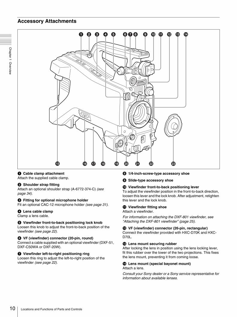
a Cable clamp attachmentAttach the supplied cable clamp.
b Shoulder strap fittingAttach an optional shoulder strap (A-6772-374-C) (see page 34).
c Fitting for optional microphone holderFit an optional CAC-12 microphone holder (see page 31).
d Lens cable clampClamp a lens cable.
e Viewfinder front-to-back positioning lock knobLoosen this knob to adjust the front-to-back position of the viewfinder (see page 22).
f VF (viewfinder) connector (20-pin, round)Connect a cable supplied with an optional viewfinder (DXF-51, DXF-C50WA or DXF-20W).
g Viewfinder left-to-right positioning ringLoosen this ring to adjust the left-to-right position of the viewfinder (see page 22).
h 1/4-inch-screw-type accessory shoe
i Slide-type accessory shoe
j Viewfinder front-to-back positioning leverTo adjust the viewfinder position in the front-to-back direction, loosen this lever and the lock knob. After adjustment, retighten this lever and the lock knob.
k Viewfinder fitting shoeAttach a viewfinder.
For information on attaching the DXF-801 viewfinder, see “Attaching the DXF-801 viewfinder” (page 25).
l VF (viewfinder) connector (26-pin, rectangular)Connect the viewfinder provided with HXC-D70K and HXC-D70L.
m Lens mount securing rubberAfter locking the lens in position using the lens locking lever, fit this rubber over the lower of the two projections. This fixes the lens mount, preventing it from coming loose.
n Lens mount (special bayonet mount)Attach a lens.
Consult your Sony dealer or a Sony service representative for information about available lenses.
Locations and Functions of Parts and Controls

Chapter 1 O
verview
o Camera control unit (CCU) connector (multi-core interface)
Set up a system with the HXCU-D70 or CCU-D50/D50P camera control unit using multi-core cables.
p TRUNK connector (D-sub 9-pin)Use for trunk signal communication between the camera and HXCU-D70 Camera Control Unit.
For information on pin assignment, see “TRUNK” in “Pin assignment” on page 79.
q Shoulder padRaise the shoulder pad fixing lever to adjust the position in the front-to-rear direction. Adjust the position for maximum convenience when operating the camera on your shoulder (see page 35).
r LENS connector (12-pin)Connect a lens cable to this connector.
Note
When connecting/disconnecting the lens cable to/from this connector, power off the camera first.
s AUDIO 1 IN (audio input 1) connector (XLR type, 3-pin, female)
Audio input connector to which you can connect audio equipment or a microphone.Audio signals input to this connector will be output from the AUDIO OUTPUT CH1 connector when the camera is used with the HXCU-D70. Audio signals input to this connector will be output from the MIC OUT connector when the camera is used with the CCU-D50/D50P. You can change the output configuration in MAINTENANCE > AUDIO in the setup menu (see page 65).
For information on pin assignment, see “AUDIO 1/2 IN” in “Pin assignment” on page 80.
t Audio input select switchSelect the audio level input to the AUDIO 1 IN connector using the select switch.+48V: To supply phantom power +48 V to condenser
microphonesMIC: When a microphone is connectedLINE: When a line-level (0 dBu) signal source is connected
Select +48V when using the microphone supplied with HXC-D70K/D70L.
u Tripod mountWhen using the camera on a tripod, attach the tripod adaptor (optional) (see page 33).
v Lens locking leverAfter inserting the lens in the lens mount, rotate the lens mount ring with this lever to lock the lens in position.After locking the lens, be sure to use the lens mount securing rubber to prevent the lens from becoming detached.
w Lens mount capRemove by pushing up the lens locking lever. When no lens is mounted, keep this cap fitted for protection from dust.
Operating and Connectors Section
Front
a FILTER (filter select) knobSwitch between four built-in ND filters. The selected filter setting appears in the viewfinder for about three seconds.
You can change a MAINTENANCE menu setting so that different white balance settings can be stored for different FILTER knob positions. This allows you to automatically obtain optimum white balance for the current shooting conditions in linkage with the filter selection.
For details, see “Adjusting the White Balance” (page 37).
b SHUTTER selectorSet to ON to use the electronic shutter. Push to SEL to switch the shutter speed or shutter mode setting. When this selector is used, the shutter speed settings appear in the viewfinder for about three seconds.
Unavailable when the camera is connected to the CCU.
FILTER knob setting ND filter
1 Clear
2 1/4 ND (attenuates light to approximately 1/4)
3 1/16 ND (attenuates light to approximately 1/16)
4 1/64 ND (attenuates light to approximately 1/64)
11Locations and Functions of Parts and Controls
12
Chapter 1 O
verview
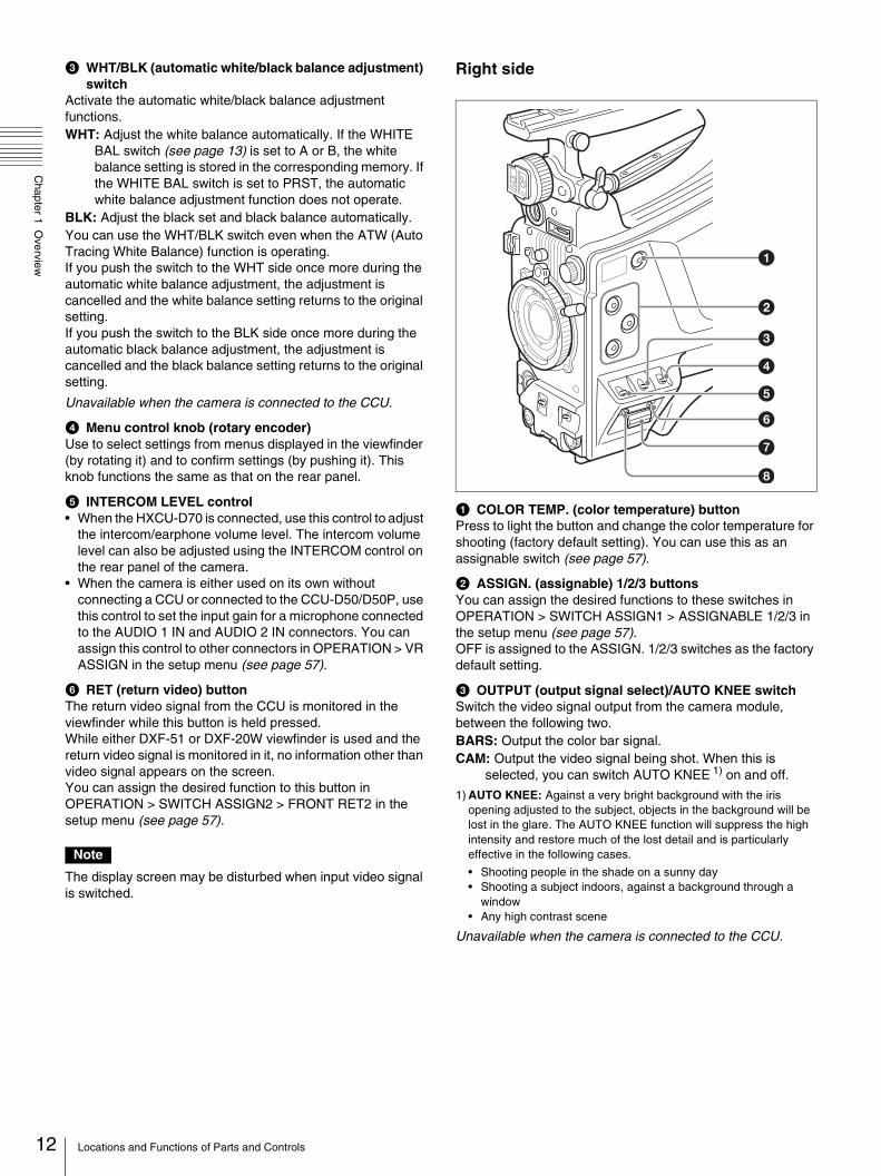
c WHT/BLK (automatic white/black balance adjustment) switch
Activate the automatic white/black balance adjustment functions.WHT: Adjust the white balance automatically. If the WHITE
BAL switch (see page 13) is set to A or B, the white balance setting is stored in the corresponding memory. If the WHITE BAL switch is set to PRST, the automatic white balance adjustment function does not operate.
BLK: Adjust the black set and black balance automatically.You can use the WHT/BLK switch even when the ATW (Auto Tracing White Balance) function is operating.If you push the switch to the WHT side once more during the automatic white balance adjustment, the adjustment is cancelled and the white balance setting returns to the original setting.If you push the switch to the BLK side once more during the automatic black balance adjustment, the adjustment is cancelled and the black balance setting returns to the original setting.
Unavailable when the camera is connected to the CCU.
d Menu control knob (rotary encoder)Use to select settings from menus displayed in the viewfinder (by rotating it) and to confirm settings (by pushing it). This knob functions the same as that on the rear panel.
e INTERCOM LEVEL control• When the HXCU-D70 is connected, use this control to adjust
the intercom/earphone volume level. The intercom volume level can also be adjusted using the INTERCOM control on the rear panel of the camera.
• When the camera is either used on its own without connecting a CCU or connected to the CCU-D50/D50P, use this control to set the input gain for a microphone connected to the AUDIO 1 IN and AUDIO 2 IN connectors. You can assign this control to other connectors in OPERATION > VR ASSIGN in the setup menu (see page 57).
f RET (return video) buttonThe return video signal from the CCU is monitored in the viewfinder while this button is held pressed.While either DXF-51 or DXF-20W viewfinder is used and the return video signal is monitored in it, no information other than video signal appears on the screen.You can assign the desired function to this button in OPERATION > SWITCH ASSIGN2 > FRONT RET2 in the setup menu (see page 57).
Note
The display screen may be disturbed when input video signal is switched.
Right side
a COLOR TEMP. (color temperature) buttonPress to light the button and change the color temperature for shooting (factory default setting). You can use this as an assignable switch (see page 57).
b ASSIGN. (assignable) 1/2/3 buttonsYou can assign the desired functions to these switches in OPERATION > SWITCH ASSIGN1 > ASSIGNABLE 1/2/3 in the setup menu (see page 57).OFF is assigned to the ASSIGN. 1/2/3 switches as the factory default setting.
c OUTPUT (output signal select)/AUTO KNEE switchSwitch the video signal output from the camera module, between the following two.BARS: Output the color bar signal.CAM: Output the video signal being shot. When this is
selected, you can switch AUTO KNEE 1) on and off.
1) AUTO KNEE: Against a very bright background with the iris opening adjusted to the subject, objects in the background will be lost in the glare. The AUTO KNEE function will suppress the high intensity and restore much of the lost detail and is particularly effective in the following cases.
• Shooting people in the shade on a sunny day• Shooting a subject indoors, against a background through a
window• Any high contrast scene
Unavailable when the camera is connected to the CCU.
Locations and Functions of Parts and Controls

Chapter 1 O
verview
d WHITE BAL (white balance memory select) switchControl adjustment of the white balance.PRST: Adjust the color temperature to the preset value (the
factory default setting: 3200K). Use this setting when you have no time to adjust the white balance.
A or B: Recall the white balance adjustment settings already stored in A or B. Push the WHT/BLK switch (see page 12) on the WHT side, to automatically adjust the white balance, and save the adjustment settings in memory A or memory B.
When this switch is adjusted, the new setting appears in the viewfinder for about three seconds.
Unavailable when the camera is connected to the CCU.
e GAIN selectorSwitch the gain of the video amplifier to match the lighting conditions during shooting. The gains corresponding to the L, M, and H settings can be selected in OPERATION > SWITCH ASSIGN 1 > GAIN L/H/M in the setup menu (see page 57). (The factory settings are L=0 dB, M=6 dB, and H=12 dB.)When this switch is adjusted, the new settings appear in the viewfinder for about three seconds.
Unavailable when the camera is connected to the CCU.
f DISPLAY/MENU switchSelect the display in the viewfinder.DISPLAY: To display various textual information and markers,
such as messages showing the camera settings and operating status, the center marker, and the safety zone marker, in addition to camera images.
OFF: Not to display textual information and markers.MENU: To display menus for camera settings, in addition to
camera images.The switch functions the same as the DISPLAY/MENU switch on the rear operation panel.
g “Memory Stick Duo” slot and access lampTake the cover off and insert a “Memory Stick Duo” into the slot. The access lamp lights in green. The lamp is lit in red while writing/reading data to/from the “Memory Stick Duo.”
Notes
• Only a “Memory Stick” of Duo size can be used with the camera.
• When the access lamp is lit in red, do not remove the “Memory Stick Duo” or turn off the camera.
• The cover cannot be closed while a “Memory Stick Duo” is inserted into the slot.
h STATUS/CANCEL switchSTATUS: To display status information of this camera in the
viewfinder when no menu is displayed with the DISPLAY/MENU switch set to DISPLAY.
CANCEL: To cancel changed settings or return the display to the previous menu when a menu is displayed in the viewfinder.
Rear
a TALLY (back tally) indicators (red/green)ON: The tally lamp lights when a tally signal is input to the
connected CCU or a call signal is generated in response to pressing of a CALL button.
OFF: The tally lamp is prevented from lighting.
b TALLY switchSet to ON to activate the TALLY indicator function.
c Menu control knob (rotary encoder)This knob functions the same as that on the front panel (see page 12).
d DISPLAY/MENU switchThis switch functions the same as that on the right panel (see page 13).
e CALL buttonWhen you press this button, the red tally lamps on the front panel of the CCU and the connected external control device (RCP/RM, etc.) will light.
* The figure above illustrates a camera without its rear cover. For information on removing the rear cover, see “Removing the Rear Cover” (page 20).
EARPHONE
INTERCOM AUDOIO 2 IN
REMOTE
DC OUT
PUSHPUSH
DC IN
LINE MIC +48V
TESTOUT
PROMPTER
SDI OUT
SDI IN/GENLOCK
13Locations and Functions of Parts and Controls

14
Chapter 1 O
verview
f INTERCOM control• When a HXCU-D70 is connected, use this control to adjust
the intercom volume level. The intercom volume level can also be adjusted using the INTERCOM LEVEL control on the front panel (see page 12).
• When the camera is either used on its own without connecting a CCU or connected to the CCU-D50/D50P, use this control to adjust the intercom volume level. You can assign this control to other connectors in OPERATION > VR ASSIGN in the setup menu (see page 57).
g INTERCOM ON/OFF switchTurn the intercom microphone output on or off. Set it to ON to communicate with a CCU or external control device.
h RET (return video) buttonThe RETURN1 signal is monitored in the viewfinder.
i EARPHONE jack (stereo, minijack)Monitor the audio output from the intercom or audio signals input to the AUDIO 1/2 IN connectors. You can select an audio output to monitor in OPERATION > EARPHONE in the setup menu (see page 58). The earphone volume level can be adjusted using the INTERCOM LEVEL control on the front panel and OPERATION > EARPHONE in the setup menu (see page 58).
j AUDIO 2 IN input select switchSelect the audio level input to the AUDIO 2 IN connector using the select switch.+48V: To supply phantom power +48 V to condenser
microphonesMIC: When a microphone is connectedLINE: When a line-level (0 dBu) signal source is connected
k REMOTE connector (8-pin)Connect a remote control unit, which makes it possible to control the camera remotely.
Note
Before connecting/disconnecting the remote control unit to/from the camera, be sure to turn off the camera power switch.
For information on pin assignment, see “REMOTE” in “Pin assignment” on page 79.
l TEST OUT connector (BNC type)Outputs an analog signal. This connector outputs one of the following signals selected on the menu: VBS, HD-SYNC, SD-SYNC, or the same Y signal that is output from the VF connector (20-pin, round).
Note
When the test out connector outputs a Y signal the same as that from the VF connector (20-pin, round), output signal format from this connector varies depending on which of the following viewfinders are connected.No viewfinder: SD component (Y) signalDXF-C50WA viewfinder: HD component (Y) signalViewfinders other than DXF-C50WA: SD component (Y)
signal
m SDI OUT connector (BNC type)Outputs an HD-SDI or SD-SDI signal. You can select the output signal format in the MAINTENANCE menu.
n DC IN (DC power supply input) connector (XLR 4-pin, female)
Refer to “DC IN connector” in “Power Supply” on page 9.
o INTERCOM connector (XLR 5-pin)Connect an XLR 5-pin headset for input and output of intercom audio signals.For information on pin assignment, see “INTERCOM” in “Pin assignment” on page 79.
p AUDIO 2 IN (audio input 2) connector (XLR type, 3-pin, female)
Audio input connector to which you can connect audio equipment or a microphone.Audio signals input to this connector will be output from the AUDIO OUTPUT CH2 connector when the camera is used with the HXCU-D70. Audio signals input to this connector will be output from the MIC OUT connector when the camera is used with the CCU-D50/D50P. You can change the settings in MAINTENANCE > AUDIO in the setup menu (see page 65).
For information on pin assignment, see “AUDIO 1/2 IN” in “Pin assignment” on page 80.
q Tail guardThis is provided for protecting the cables connected to the connectors on the rear panel.
r DC OUT (DC power supply output) connector (4-pin, female)
Refer to “DC OUT connector” in “Power Supply” on page 9.
s PROMPTER/GENLOCK (prompter signal output/external sync signal input) connector (BNC type)
• When a CCU is connected, this connector outputs a VBS prompter signal.
• When the camera is used on its own without connecting a CCU, use this connector for input of an external sync signal (BB or 3-level sync). If a VBS signal is input, you can check the input image by pressing the RET button.
t SDI IN connector (BNC type)Displays HD-SDI signal input from the SDI IN connector when the RET button is pressed in standalone status. You can select the signal to be displayed in the viewfinder in MAINTENANCE > EXT RETURN in the setup menu (see page 68).
Notes
• HD-SDI signals in specified format can only be input to the SDI IN connector. You can select the desired format in MAINTENANCE > OUTPUT FORMAT in the setup menu (see page 66).
• Signals input to the SDI IN connector can be displayed in the following viewfinders:– CBK-VF01 (supplied with HXC-D70K/D70L)– DXF-C50WA
• Signals input to the SDI IN connector cannot be displayed in the viewfinder when SD-SDI is selected in MAINTENANCE > SDI OUT in the setup menu (see page 66).
Locations and Functions of Parts and Controls
Chapter 1 O
verview
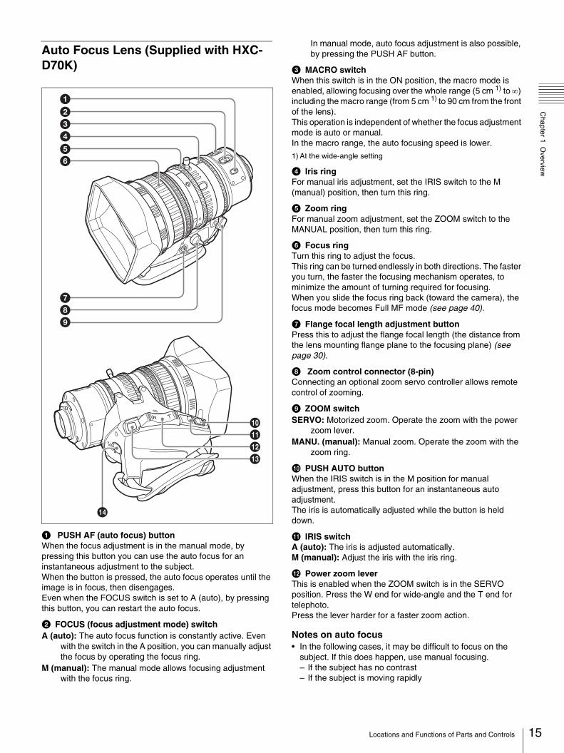
Auto Focus Lens (Supplied with HXC-D70K)
a PUSH AF (auto focus) buttonWhen the focus adjustment is in the manual mode, by pressing this button you can use the auto focus for an instantaneous adjustment to the subject.When the button is pressed, the auto focus operates until the image is in focus, then disengages.Even when the FOCUS switch is set to A (auto), by pressing this button, you can restart the auto focus.
b FOCUS (focus adjustment mode) switchA (auto): The auto focus function is constantly active. Even
with the switch in the A position, you can manually adjust the focus by operating the focus ring.
M (manual): The manual mode allows focusing adjustment with the focus ring.
In manual mode, auto focus adjustment is also possible, by pressing the PUSH AF button.
c MACRO switchWhen this switch is in the ON position, the macro mode is enabled, allowing focusing over the whole range (5 cm 1) to ∞) including the macro range (from 5 cm 1) to 90 cm from the front of the lens).This operation is independent of whether the focus adjustment mode is auto or manual.In the macro range, the auto focusing speed is lower.
1) At the wide-angle setting
d Iris ringFor manual iris adjustment, set the IRIS switch to the M (manual) position, then turn this ring.
e Zoom ringFor manual zoom adjustment, set the ZOOM switch to the MANUAL position, then turn this ring.
f Focus ringTurn this ring to adjust the focus.This ring can be turned endlessly in both directions. The faster you turn, the faster the focusing mechanism operates, to minimize the amount of turning required for focusing.When you slide the focus ring back (toward the camera), the focus mode becomes Full MF mode (see page 40).
g Flange focal length adjustment buttonPress this to adjust the flange focal length (the distance from the lens mounting flange plane to the focusing plane) (see page 30).
h Zoom control connector (8-pin)Connecting an optional zoom servo controller allows remote control of zooming.
i ZOOM switchSERVO: Motorized zoom. Operate the zoom with the power
zoom lever.MANU. (manual): Manual zoom. Operate the zoom with the
zoom ring.
j PUSH AUTO buttonWhen the IRIS switch is in the M position for manual adjustment, press this button for an instantaneous auto adjustment.The iris is automatically adjusted while the button is held down.
k IRIS switchA (auto): The iris is adjusted automatically.M (manual): Adjust the iris with the iris ring.
l Power zoom leverThis is enabled when the ZOOM switch is in the SERVO position. Press the W end for wide-angle and the T end for telephoto.Press the lever harder for a faster zoom action.
Notes on auto focus• In the following cases, it may be difficult to focus on the
subject. If this does happen, use manual focusing.– If the subject has no contrast– If the subject is moving rapidly
15Locations and Functions of Parts and Controls

16
Chapter 1 O
verview
– When shooting point light sources, under street lighting or at night
– When there are very bright objects close to the subject– When shooting through a glass window
• If there are a number of objects within the screen at close and far range, the focus may not be on the intended subject. In this case, with the subject on which you want to focus in the center of the screen, press the PUSH AF button.
• After focusing with the PUSH AF button, if you operate the zoom or adjust the iris, the depth of field may become shallower, losing crisp focus. In such cases, press the PUSH AF button once more.
• If you focus at wide-angle then zoom to telephoto, the subject may no longer be in focus.
Note on zoom speedDepending on the shooting distance, the zoom speed may fall as the lens approaches the telephoto end.
m RET (return video) buttonThe RETURN1 signal is monitored in the viewfinder.
n VTR buttonYou can assign the desired function to this button in OPERATION > SWITCH ASSIGN2 > LENS VTR S/S in the setup menu (see page 57).
Viewfinder (supplied with HXC-D70K/D70L)
a PlugConnect to the VF connector (rectangular) on the camera.
b StopperPrevents the viewfinder from coming off the camera when it is slid from side to side.
c Eyecup
d Diopter adjustment ringAllows for optimal focus adjustment.
e Tally indicatorWhen an abnormality occurs, the tally indicator flashes to indicate a warning.
f EyepieceYou can raise this up when required by the situation.
g Viewfinder barrelYou can raise this up or rotate when required by the situation.
h PEAKING controlTurning this control clockwise adjusts the picture sharpness, and makes focusing easier. This control has no effect on the output signals of the camera.
i CONTRAST controlAdjust the contrast of the screen. This control has no effect on the output signals of the camera.
j BRIGHT controlAdjust the brightness of the screen. This control has no effect on the output signals of the camera.
k TALLY switchControl the tally indicator located on the front of the viewfinder.HIGH: The tally indicator brightness is set to high.OFF: The tally indicator is disabled.LOW: The tally indicator brightness is set to low.
l ZEBRA (zebra pattern) switchControl the zebra pattern display in the viewfinder as follows.ON: Display a zebra pattern.OFF: Do not display a zebra pattern.
m DISPLAY switchTurn the display of text information on and off.ON: Display text information.OFF: Do not display text information.
n MIRROR switchThe image display on the monitor screen becomes reversed horizontally or vertically when the viewfinder barrel is raised up or rotated. Use this switch to control the image display in such situation.L/R: Reverse the image horizontally.OFF: Do not reverse the image.B/T: Reverse the image vertically.
o Viewfinder cable
p Microphone holder
Locations and Functions of Parts and Controls

Chapter 1 O
verview
Viewfinder Screen Display
Besides the video image, the viewfinder can display characters and messages showing the camera settings and operation status, as well as items such as a center marker or safety-zone marker.
When the DISPLAY/MENU switch is set to DISPLAYItems set to ON using the menu or related switches will be displayed.
a TALK indicationDisplayed when the intercom microphone is set to ON.
b D.EX indicationDisplayed when the digital extender function is set to ON.
c EX (lens extender) indicationDisplayed when a lens extender is in use.
d Zoom position indicationIndicates the approximate position of the zoom lens variator between wide angle (0) and telephoto (99 [infinity]).
e ! indicationBy using the ‘!’ IND function, the '!' indication appears in the viewfinder when non-standard or abnormal conditions are found.
For details, see OPERATION > ‘!’ IND in the setup menu (page 55).
f Focus position indicationShows the focus position of a zoom lens as a numeric value (0 to 255 [infinity]).
g Voltage indicationIndicates the power voltage supplied to the camera.
h DIAG indicationIndicates self-diagnostic information.
i Message
j AF (auto focus) indicationDisplays the auto focus status.FULL: Full MF (full manual focus) modeMF *: Manual focus assist modeAF: Auto focus mode
k 5600K mode indicationDisplayed when the internal electrical filter (5600K) is set to ON.
l Filter indicationDisplays the type of ND filter currently selected with a number (1, 2, 3, or 4).
m ECC indicationDisplays the type of electrical CC filter (A to D) currently selected.
n White balance memory indicationShows the currently selected white balance automatic adjustment memory. This is not displayed when a CCU is connected.W:A: The WHITE BAL switch is set to A.W:B: The WHITE BAL switch is set to B. W:P: The WHITE BAL switch is set to PRST.
o Gain value indicationShows the video gain value (dB) set with the GAIN selector.
p Shutter/ECS indicationDisplays the shutter/ECS status. Nothing is displayed if the electronic shutter is set to OFF.
q Audio level metersIndicates the audio levels input to the AUDIO 1 IN and AUDIO 2 IN connectors.
r F-value indicationIndicates the lens F (iris opening) value.
s Return video indicationDisplayed while the RET button is pressed.
When the STATUS/CANCEL switch is pressed toward STATUSThe status display appears when you press the STATUS/CANCEL switch toward STATUS after pressing the DISPLAY/MENU switch toward DISPLAY or when you push on the menu control knob on the rear panel.Video formats and the adjusted items (not default) are indicated in the status display.
a Format indicationThe current video format is displayed.
E X Z 9 9 ! F 2 5D . E X 1 2 . 0T A L K C A M
F U L L5600 R E T
5V?
11 A W: A 12dB E C S 1
2 C L
1 0 8 0 5 9 . 9 4 i
! N D : 1! W : A! 5 6 0 0 K : O F F! G A I N : H! S H U T T : 1 / 1 0 0! F A N : A U T O 1! E X T : O F F1 F O R M O T : 5 9 . 9 4 i
17Viewfinder Screen Display
18
Chapter 1 O
verview
b ‘!’ indication areaThis area is used to display abnormal statuses, using the ‘!’ IND function. Display options can be set, using the menu.
For details, see OPERATION > ‘!’ IND in the setup menu (page 55).
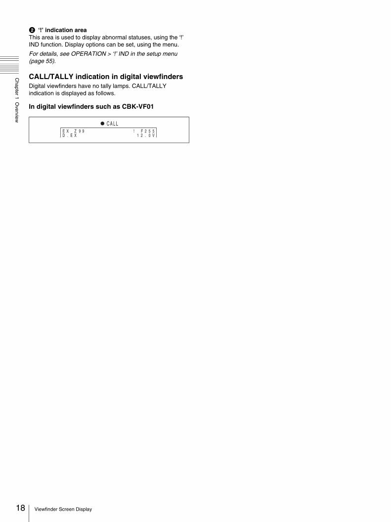
CALL/TALLY indication in digital viewfindersDigital viewfinders have no tally lamps. CALL/TALLY indication is displayed as follows.
In digital viewfinders such as CBK-VF01
E X Z 9 9 ! F 2 5D . E X 1 2 . 0
5V
C A L L
Viewfinder Screen Display
hapter2
CPreparationsChapter 2 P
reparations
Connecting a Camera Control Unit (CCU)
When operating the camera in a system with a CCU, connect between the CCU connector of the camera and the CAMERA connector of the CCU, using a multi-core cable.When required, secure the cable, using the supplied cable clamp belt.
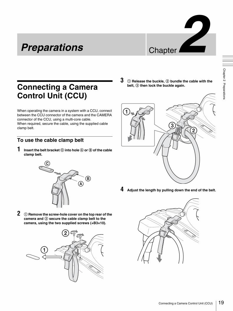
To use the cable clamp belt
1 Insert the belt bracket C into hole A or B of the cable clamp belt.
2 1 Remove the screw-hole cover on the top rear of the camera and 2 secure the cable clamp belt to the camera, using the two supplied screws (+B3×10).
3 1 Release the buckle, 2 bundle the cable with the belt, 3 then lock the buckle again.
4 Adjust the length by pulling down the end of the belt.
AB
C
1
2
23
1
19Connecting a Camera Control Unit (CCU)
20
Chapter 2 P
reparations
Standalone Operation
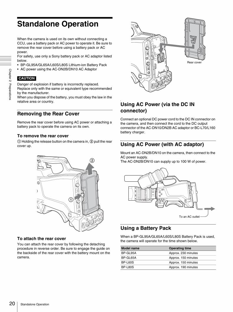
When the camera is used on its own without connecting a CCU, use a battery pack or AC power to operate it. Be sure to remove the rear cover before using a battery pack or AC power.For safety, use only a Sony battery pack or AC adaptor listed below.• BP-GL95A/GL65A/L60S/L80S Lithium-ion Battery Pack• AC power using the AC-DN2B/DN10 AC Adaptor
CAUTION
Danger of explosion if battery is incorrectly replaced. Replace only with the same or equivalent type recommended by the manufacturer.When you dispose of the battery, you must obey the law in the relative area or country.
Removing the Rear Cover
Remove the rear cover before using AC power or attaching a battery pack to operate the camera on its own.
To remove the rear cover1 Holding the release button on the camera in, 2 pull the rear cover up.
To attach the rear coverYou can attach the rear cover by following the detaching procedure in reverse order. Be sure to engage the guide on the backside of the rear cover with the battery mount on the camera.
Using AC Power (via the DC IN connector)
Connect an optional DC power cord to the DC IN connector on the camera, and then connect the cord to the DC output connector of the AC-DN10/DN2B AC adaptor or BC-L70/L160 battery charger.
Using AC Power (with AC adaptor)
Mount an AC-DN2B/DN10 on the camera, then connect to the AC power supply.The AC-DN2B/DN10 can supply up to 100 W of power.
Using a Battery Pack
When a BP-GL95A/GL65A/L60S/L80S Battery Pack is used, the camera will operate for the time shown below.
Model name Operating time
BP-GL95A Approx. 230 minutes
BP-GL65A Approx. 150 minutes
BP-L60S Approx. 150 minutes
BP-L80S Approx. 190 minutes
Rear cover
To an AC outlet
Standalone Operation
Chapter 2 P
reparations
Note
The battery pack operating time depends on the frequency of use of the battery pack, and the ambient temperature when used.
Before use, charge the battery pack with a charger suitable for each battery.
For details on the battery charging procedure, refer to the battery charger operation manual.
Note on using the battery packA warm battery pack may not be able to be fully recharged.
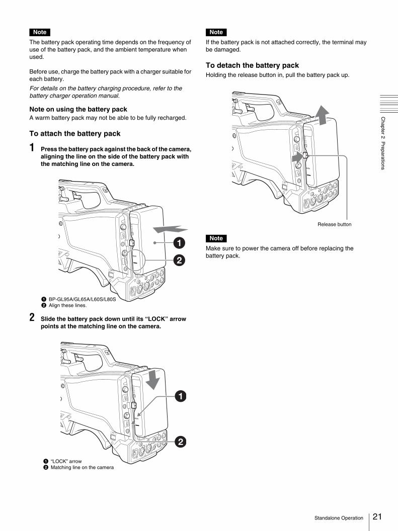
To attach the battery pack
1 Press the battery pack against the back of the camera, aligning the line on the side of the battery pack with the matching line on the camera.
2 Slide the battery pack down until its “LOCK” arrow points at the matching line on the camera.
Note
If the battery pack is not attached correctly, the terminal may be damaged.
To detach the battery packHolding the release button in, pull the battery pack up.
Note
Make sure to power the camera off before replacing the battery pack.
1 BP-GL95A/GL65A/L60S/L80S2 Align these lines.
1 “LOCK” arrow2 Matching line on the camera
Release button
21Standalone Operation
22
Chapter 2 P
reparations
Attaching the Viewfinder
CAUTION
When the viewfinder is attached, do not leave the camera with the eyepiece facing the sun. Direct sunlight can enter through the eyepiece, be focused in the viewfinder and cause fire.
Attaching the Supplied Viewfinder
Notes
When attaching the viewfinder, make notes of the following points.• Be sure to power off the camera before coupling the
viewfinder connector to the camera’s VF connector (rectangular). If you make this connection when the camera power is on, the viewfinder may not function properly.
• Couple the viewfinder connector firmly to the camera’s VF connector (rectangular). If the coupling is loose, noise may appear on the video or the tally indicator may not operate properly.
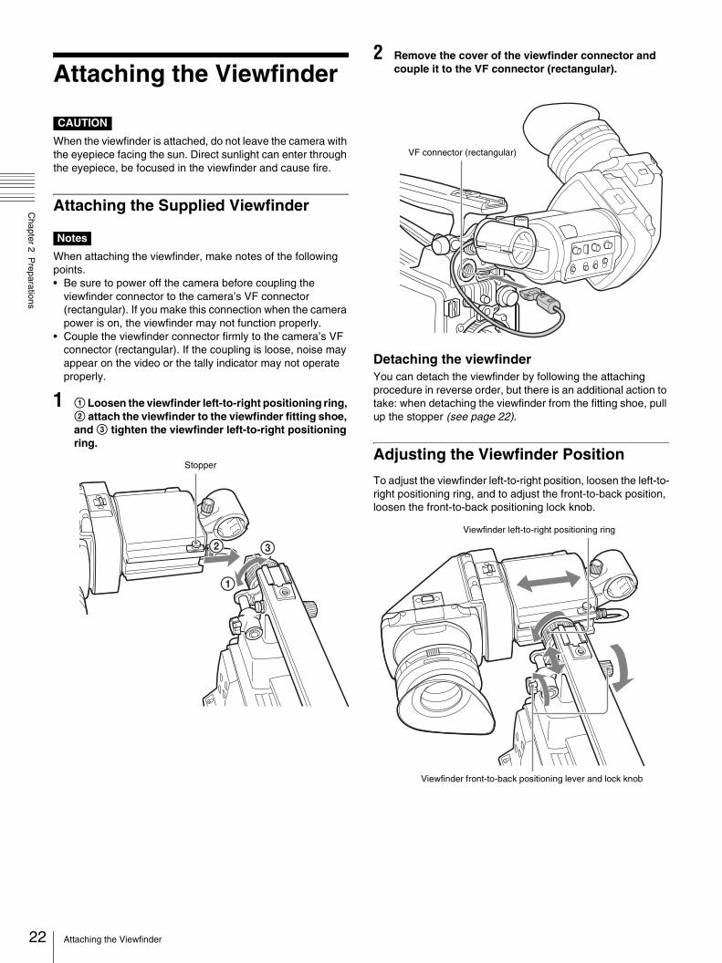
1 1 Loosen the viewfinder left-to-right positioning ring, 2 attach the viewfinder to the viewfinder fitting shoe, and 3 tighten the viewfinder left-to-right positioning ring.
2 Remove the cover of the viewfinder connector and couple it to the VF connector (rectangular).
Detaching the viewfinderYou can detach the viewfinder by following the attaching procedure in reverse order, but there is an additional action to take: when detaching the viewfinder from the fitting shoe, pull up the stopper (see page 22).
Adjusting the Viewfinder Position
To adjust the viewfinder left-to-right position, loosen the left-to-right positioning ring, and to adjust the front-to-back position, loosen the front-to-back positioning lock knob.
Stopper
VF connector (rectangular)
Viewfinder front-to-back positioning lever and lock knob
Viewfinder left-to-right positioning ring
Attaching the Viewfinder

Chapter 2 P
reparations
Adjusting the Viewfinder Angle
You can adjust the angle of the viewfinder.
To reverse the display (image/text indication) verticallyThe viewfinder can be rotated as much as 180 degrees toward the direction facing the subject.When you do this, the picture and other information displayed in the viewfinder appear upside down.To restore the normal display, set the MIRROR switch on the rear panel of the viewfinder to B/T.
Lifting Up the Viewfinder Barrel and Eyepiece
You can view the LCD screen inside the viewfinder or its mirrored image by lifting up the viewfinder barrel or the eyepiece.This section describes how to lift up the viewfinder barrel and detach it. The eyepiece can also be lifted up and detached in the same way.
To raise up the viewfinder barrel1 Push the clip on the bottom to release and 2 flip up the viewfinder barrel.It locks at the 120-degree position.
Normally use it in the locked position.Although you can open it farther from the lock position, once return it to the closed position to lock it at the 120-degree position again.
LCD screen
1
2
23Attaching the Viewfinder

24
Chapter 2 P
reparations
To detach the viewfinder barrel
1 Push the clip on the bottom to release.
2 Flip up the viewfinder barrel.
3 Slide the knob on the top to the opposite side of the viewfinder barrel.
4 Detach the viewfinder barrel by horizontally sliding it.
To reverse the display (image/text indication) horizontallyBy setting the MIRROR switch on the rear panel of the viewfinder to L/R, you can reverse the picture and other information displayed in the viewfinder horizontally.
Adjusting the Viewfinder Focus and Screen
To adjust the viewfinder focusTurn the diopter adjustment ring until the viewfinder image is sharpest.
To adjust the viewfinder screenAdjust the peaking, contrast, and brightness of the viewfinder screen with the controls shown below.Peaking: Adjust using the PEAKING controlContrast: Adjust using the CONTRAST controlBright: Adjust using the BRIGHT control
Diopter adjustment ring
1 PEAKING control2 CONTRAST control3 BRIGHT control
Attaching the Viewfinder

Chapter 2 P
reparations
Attaching an Optional Viewfinder
Attaching the DXF-20W viewfinder
1 1 Loosen the left-to-right positioning ring of the camera, and 2 engage the slide rail on the backside of the viewfinder with the viewfinder fitting shoe.
2 1 Slide the viewfinder in the direction shown by the arrow to the required mounting position, 2 tighten the left-to-right positioning ring of the camera, and 3 plug the viewfinder connector into the VF connector (20-pin, round) of the camera, and clip the cable into the cable clamp.
Notes
• Be sure to power off the camera before plugging the viewfinder connector into the VF connector on the camera. If the connector is plugged in while the power is on, the viewfinder may not operate correctly.
• Make sure that the viewfinder connector is pushed fully into the VF connector (20-pin, round) on the camera. If the connector is not firmly connected, the image may break up, or the tally light may not operate properly.
To detach the DXF-20W viewfinderTo detach the viewfinder from the camera, conduct the attachment procedure in reverse. When removing the viewfinder from the camera, pull up the stopper.
Attaching the DXF-801 viewfinderReplace the viewfinder fitting shoe, following the steps below before attaching the DXF-801 viewfinder.
Note
The following accessories are not supplied with the HXC-D70K/D70L. (A 3.5-type color LCD viewfinder is supplied with the HXC-D70K/D70L.)
– Viewfinder fitting shoe (service part number: 3-776-885-03)
– Hexagonal wrench (size: 2.5 mm) (service part number: 7-700-736-04, 7-721-130-53)
1 With the supplied hexagonal wrench (size: 2.5 mm), remove the bolts and spring washers, and detach the viewfinder fitting shoe from the VF shoe fixing bracket.
2 Loosen the viewfinder left-to-right positioning ring and detach it from the viewfinder fitting shoe.
3 Attach the ring to the supplied viewfinder fitting shoe and tighten the ring.
2
1
Stopper
Slide rail
Viewfinder fitting shoe
Left-to-right positioning ring
1
3
2
Cable clamp
Viewfinder connector
VF connector (20-pin, round)
VF shoe fixing bracket
Viewfinder fitting shoe
Left-to-right positioning ring
Positioning ring
DXF-801 viewfinder fitting shoe
25Attaching the Viewfinder

26
Chapter 2 P
reparations
4 Attach the provided viewfinder shoe to the camera.Align the holes in the rear of the viewfinder fitting shoe with the two pins on the VF shoe fixing bracket. Be sure the cutout in the viewfinder fitting shoe facing upward.
5 With the spring washers and bolts removed in step 1, fasten the viewfinder fitting shoe to the VF shoe fixing bracket.
Attaching the DXF-C50WA/51 viewfinder
1 Slide the bracket fully into the accessory shoe of the camera until the end stops.
2 Tighten the fixing ring to secure the viewfinder.
3 Couple the connector to the VF connector (20-pin, round) of the camera, and clip the connecting cable into the cable clamp as shown in the following figure.
To detach the DXF-C50WA/51 viewfinderLoosen the fixing ring and pull the viewfinder out of the accessory shoe in the opposite direction.
Attaching a 5-type color LCD viewfinderA 5-type color LCD viewfinder can be panned over an angle of 30° to the right and 30° to the left. To rotate the viewfinder (for panning) up to 90° in the left and right directions, attach the optional accessory shoe kit (service part number: A-8274-968-B), or the accessory shoe supplied with the camera to the camera head grip taking the following steps.
Detaching the accessory shoe
1 Pull up the stopper and remove the plate spring.
2 Detach the accessory shoe after loosening the four screws (K3×8).
Attaching the accessory shoe
Pins
Holes to align with the pins (rear of the viewfinder shoe)
Fixing ring
Bracket
Accessory shoe
Stopper
Cable clamp
VF connector of the camera
Connecting cable
Screws (K3×8) or (K3×12)
Stopper
Plate springAccessory shoe
Plate
Screw (M2x5)
Attaching the Viewfinder
Chapter 2 P
reparations
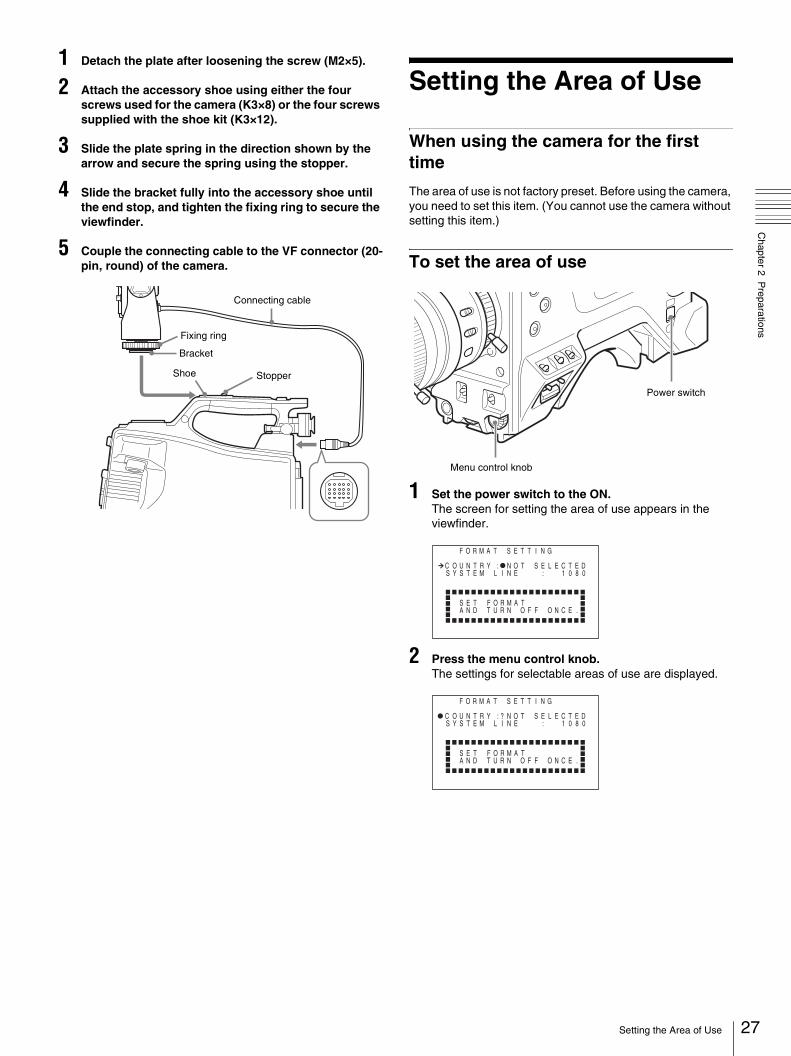
1 Detach the plate after loosening the screw (M2×5).
2 Attach the accessory shoe using either the four screws used for the camera (K3×8) or the four screws supplied with the shoe kit (K3×12).
3 Slide the plate spring in the direction shown by the arrow and secure the spring using the stopper.
4 Slide the bracket fully into the accessory shoe until the end stop, and tighten the fixing ring to secure the viewfinder.
5 Couple the connecting cable to the VF connector (20-pin, round) of the camera.
Setting the Area of Use
When using the camera for the first time
The area of use is not factory preset. Before using the camera, you need to set this item. (You cannot use the camera without setting this item.)
To set the area of use
1 Set the power switch to the ON.The screen for setting the area of use appears in the viewfinder.
2 Press the menu control knob.The settings for selectable areas of use are displayed.
Connecting cable
Bracket
Shoe
Fixing ring
Stopper
Menu control knob
Power switch
F O M A T S E T T I N G
C O U N T R
R
Y : N O T S E L E C TS Y S T E M L I N E : 1 0 8
S E T F O R M A TA N D T U R N O F F O N C E .
E D0
F O M A T S E T T I N G
?C O U N T R
R
Y : N O T S E L E C TS Y S T E M L I N E : 1 0 8
S E T F O R M A TA N D T U R N O F F O N C E .
E D0
27Setting the Area of Use
28
Chapter 2 P
reparations
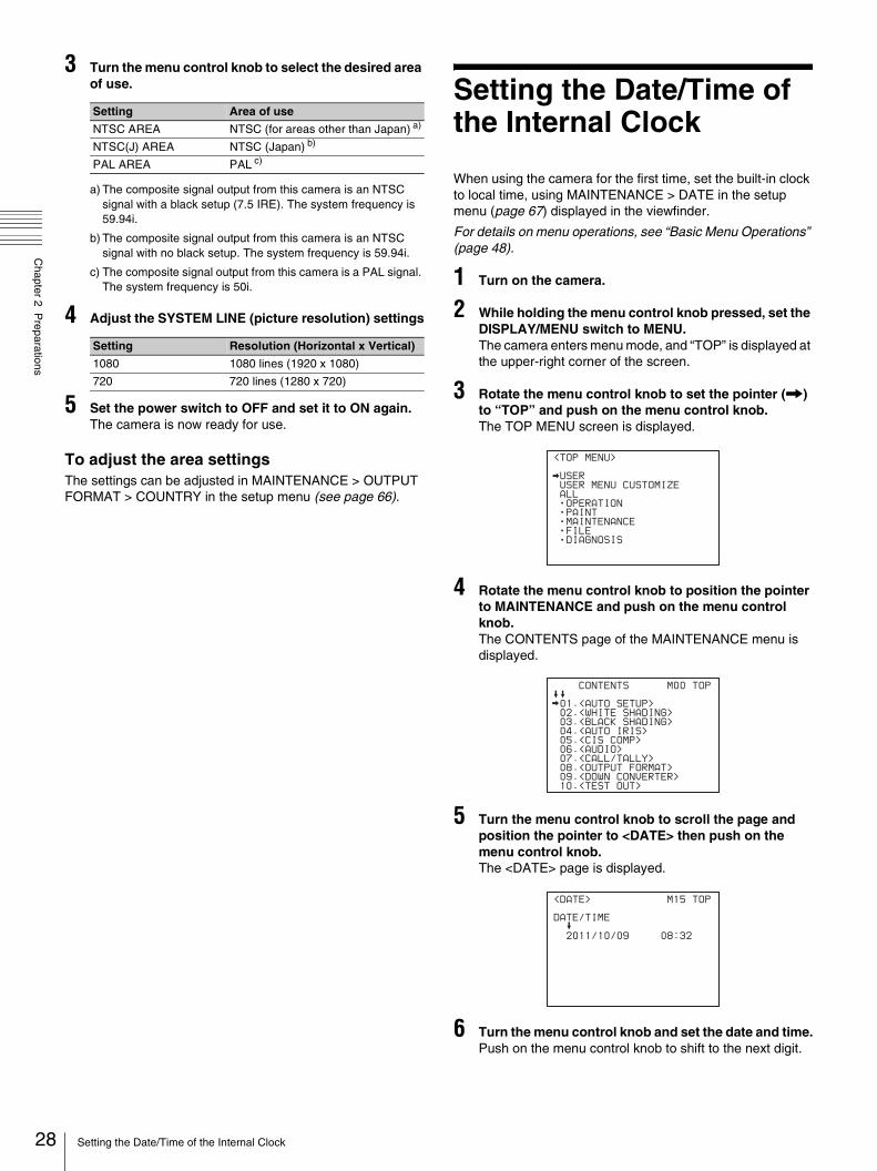
3 Turn the menu control knob to select the desired area of use.
a) The composite signal output from this camera is an NTSC signal with a black setup (7.5 IRE). The system frequency is 59.94i.
b) The composite signal output from this camera is an NTSC signal with no black setup. The system frequency is 59.94i.
c) The composite signal output from this camera is a PAL signal. The system frequency is 50i.
4 Adjust the SYSTEM LINE (picture resolution) settings
5 Set the power switch to OFF and set it to ON again.The camera is now ready for use.
To adjust the area settingsThe settings can be adjusted in MAINTENANCE > OUTPUT FORMAT > COUNTRY in the setup menu (see page 66).
Setting the Date/Time of the Internal Clock
When using the camera for the first time, set the built-in clock to local time, using MAINTENANCE > DATE in the setup menu (page 67) displayed in the viewfinder.
For details on menu operations, see “Basic Menu Operations” (page 48).
1 Turn on the camera.
2 While holding the menu control knob pressed, set the DISPLAY/MENU switch to MENU.The camera enters menu mode, and “TOP” is displayed at the upper-right corner of the screen.
3 Rotate the menu control knob to set the pointer (,) to “TOP” and push on the menu control knob.The TOP MENU screen is displayed.
4 Rotate the menu control knob to position the pointer to MAINTENANCE and push on the menu control knob.The CONTENTS page of the MAINTENANCE menu is displayed.
5 Turn the menu control knob to scroll the page and position the pointer to <DATE> then push on the menu control knob.The <DATE> page is displayed.
6 Turn the menu control knob and set the date and time.Push on the menu control knob to shift to the next digit.
Setting Area of use
NTSC AREA NTSC (for areas other than Japan) a)
NTSC(J) AREA NTSC (Japan) b)
PAL AREA PAL c)
Setting Resolution (Horizontal x Vertical)
1080 1080 lines (1920 x 1080)
720 720 lines (1280 x 720)
<TOP MENU>
USER
USER MENU CUSTOMIZE
ALL
OPERATION
PAINT
MAINTENANCE
FILE
DIAGNOSIS
CONTENTS M00 TOP
01.<AUTO SETUP>
02.<WHITE SHADING>
03.<BLACK SHADING>
04.<AUTO IRIS>
05.<CIS COMP>
06.<AUDIO>
07.<CALL/TALLY>
08.<OUTPUT FORMAT>
09.<DOWN CONVERTER>
10.<TEST OUT>
<DATE> M15 TOP
DATE/TIME
2011/10/09 08:32
Setting the Date/Time of the Internal Clock

Chapter 2 P
reparations
7 When the date/time setting is completed, set the DISPLAY/MENU switch to OFF to exit menu mode. Mounting and Adjusting
the Lens
First power off the camera, and then mount the lens using the following procedure.
For information about using the lens, refer to the operation manual for the lens.
1 Push the lens locking lever up and remove the lens mount cap from the lens mount.
2 Align the center pin on the lens with the center slot in the lens mount, and insert the lens into the mount.
3 Holding the lens in place, push the lens locking lever down to lock the lens.
Caution
If the lens is not firmly locked, it may come off while the camera is being used. This could cause a serious accident. Make sure the lens is firmly locked. It is recommended that the lens mount securing rubber be put on the lens locking lever as illustrated above.
4 Connect the lens cable to the LENS connector.
Lens mount securing rubber
29Mounting and Adjusting the Lens

30
Chapter 2 P
reparations
5 Secure the lens cable with the cable clamps.
If you have attached an aberration correction lensThe aberration correction function is activated automatically. Starting the camera with an aberration correction lens may require more time than normally because of data loading at start-up.The lens supplied with the HXC-D70K is an aberration correction lens. Contact your Sony dealer or a Sony service representative for information about other aberration correction lenses.
Adjusting the Flange Focal Length
If the lens does not stay in focus properly as you zoom from telephoto to wide angle, adjust the flange focal length (the distance from the plane of the lens mounting flange to the imaging plane). Make this adjustment just one time after mounting or changing the lens.When carrying out the adjustment, use the supplied flange focal length adjustment chart as the subject.
Notes
• If you use a subject with insufficient contrast, or move the camera or subject during adjustment, this will cause an adjustment error.
• Place the subject (the flange focal length adjustment chart) so that it appears at the center of the screen at the telephoto end. Arrange so that no nearby object (no object closer to the camera than the chart) enters the screen at the wide-angle end.
Carrying out the adjustment
When using the auto focus lensWith the lens supplied with the HXC-D70K, zoom and focus operations automatically adjust the flange focal length.
1 Open the iris, position the supplied flange focal length adjustment chart approximately three meters (10 ft) away from the camera, and arrange the lighting to obtain a satisfactory video output.
2 Set the ZOOM switch to SERVO (power zoom mode).
3 Activate the AUTO FLANGE BACK function using MAINTENANCE > OTHERS 1 > AUTO FLANGE BACK in the setup menu (see page 68).
4 Make sure the message “AFB OK” appears after the setting.
When using a non-auto focus lens
1 Set the iris to manual.
2 Open the iris, position the supplied flange focal length adjustment chart approximately three meters (10 ft) away from the camera, and arrange the lighting to obtain a satisfactory video output.
3 Loosen the fixing screws on the F.f or F.B ring (flange focal length adjustment ring).
4 Use manual or power zoom to set the lens to telephoto.
5 Point the camera at the chart by turning the focus ring and focus on it.
6 Set the zoom ring to wide angle.
7 Turn the F.f or F.B ring until the chart is in focus, being careful not to disturb the focus ring.
8 Repeat steps 4 to 7 until the chart stays in focus all the way from wide angle to telephoto.
9 Tighten the F.f or F.B ring fixing screws.
About 3 m (10 ft)
Mounting and Adjusting the Lens

Chapter 2 P
reparations
Preparing the Audio Input System
Connecting a Microphone to the AUDIO 1 IN Connector
Attach a microphone (supplied with HXC-D70K/D70L) to the microphone holder of the supplied viewfinder.
1 Loosen the screw and open the microphone holder clamp.
2 Place the microphone in the microphone holder.
1 Place the microphone in the holder so that “UP” is at the top.
2 Close the microphone holder.3 Tighten the screw.
On how to perform this operation, refer to the operation manual for the microphone.
3 Plug the microphone cable into the AUDIO 1 IN connector.
4 Secure the microphone cable with the cable clamp.
5 Set the AUDIO 1 IN input select switch as follows.Set the input select switch as indicated below, depending on the power supply type of the microphone.Microphone not requiring a phantom power supply from the camera: MICMicrophone requiring a phantom power supply from the camera: +48V
6 Switch the input level to match the sensitivity of the microphone used.When the camera is used on its own, switch the input level by changing the setting of either MAINTENANCE > AUDIO (factory default setting is –60 dB) or OPERATION > VR ASSIGN in the setup menu. For details, see page 65 or page 57.
Notes
• If the input level on the camera is not at an appropriate setting for the microphone sensitivity, loud sounds may be distorted, and the signal-to-noise ratio may be affected.
• In order for the AUDIO 1 IN and AUDIO 2 IN connectors on the camera to be able to provide a phantom 48 V power supply, female XLR connectors (3-pin) are fitted. If the microphone cable has a female connector, use an adaptor.
Connecting a Microphone to the AUDIO 2 IN Connector
You can connect a monaural microphone to the AUDIO 2 IN connector, using an optional CAC-12 microphone holder.The following is the procedure for attaching an electret condenser microphone such as the ECM-674/678.
1 Attach the CAC-12 microphone holder.
Microphone holder clamp
2 3
31Preparing the Audio Input System
32
Chapter 2 P
reparations
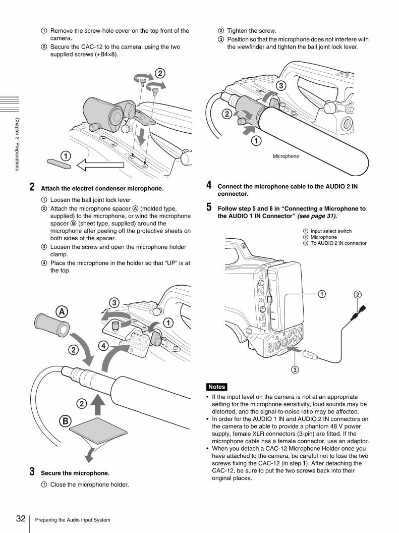
1 Remove the screw-hole cover on the top front of the camera.
2 Secure the CAC-12 to the camera, using the two supplied screws (+B4×8).
2 Attach the electret condenser microphone.
1 Loosen the ball joint lock lever.
2 Attach the microphone spacer A (molded type, supplied) to the microphone, or wind the microphone spacer B (sheet type, supplied) around the microphone after peeling off the protective sheets on both sides of the spacer.
3 Loosen the screw and open the microphone holder clamp.
4 Place the microphone in the holder so that “UP” is at the top.
3 Secure the microphone.
1 Close the microphone holder.
2 Tighten the screw.3 Position so that the microphone does not interfere with
the viewfinder and tighten the ball joint lock lever.
4 Connect the microphone cable to the AUDIO 2 IN connector.
5 Follow step 5 and 6 in “Connecting a Microphone to the AUDIO 1 IN Connector” (see page 31).
Notes
• If the input level on the camera is not at an appropriate setting for the microphone sensitivity, loud sounds may be distorted, and the signal-to-noise ratio may be affected.
• In order for the AUDIO 1 IN and AUDIO 2 IN connectors on the camera to be able to provide a phantom 48 V power supply, female XLR connectors (3-pin) are fitted. If the microphone cable has a female connector, use an adaptor.
• When you detach a CAC-12 Microphone Holder once you have attached to the camera, be careful not to lose the two screws fixing the CAC-12 (in step 1). After detaching the CAC-12, be sure to put the two screws back into their original places.
2
1
A
B
2
42
1
3
1
2
3
Microphone
1 Input select switch2 Microphone3 To AUDIO 2 IN connector
Preparing the Audio Input System
Chapter 2 P
reparations
Attaching a UHF Portable Tuner (for a UHF Wireless Microphone System)
To use a Sony UHF wireless microphone system, power the camera off and then fit one of the following UHF portable tuners.• WRR-855S UHF Synthesized Tuner Unit• WRR-860A/861/862 UHF Synthesized Diversity Tuner• DWR-S01D Digital Wireless Receiver
For details of these units, refer to the operation manuals for them.
Notes
• The optional BTA-8011) Portable Tuner Mount Adapter and WRR Mount Bracket (service part number: A-8278-057-B) are required to attach a UHF portable tuner.
• The DWA-01D Digital Wireless Adaptor is required to attach a digital wireless receiver.
1) Required when WRR-855 is used.
For details, contact your Sony dealer or a Sony service representative.
Mounting the Camera to a Tripod
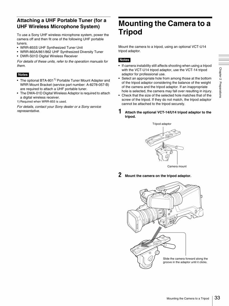
Mount the camera to a tripod, using an optional VCT-U14 tripod adaptor.
Notes
• If camera instability still affects shooting when using a tripod with the VCT-U14 tripod adaptor, use the VCT-14 tripod adaptor for professional use.
• Select an appropriate hole from among those at the bottom of the tripod adaptor considering the balance of the weight of the camera and the tripod adaptor. If an inappropriate hole is selected, the camera may fall over resulting in injury.
• Check that the size of the selected hole matches that of the screw of the tripod. If they do not match, the tripod adaptor cannot be attached to the tripod securely.
1 Attach the optional VCT-14/U14 tripod adaptor to the tripod.
2 Mount the camera on the tripod adaptor.
Tripod adaptor
Camera mount
Slide the camera forward along the groove in the adaptor until it clicks.
33Mounting the Camera to a Tripod

34
Chapter 2 P
reparations
To remove the camera from the tripod adaptorHold down the red button and pull the lever in the direction of the arrow.
If the pin of the tripod adaptor does not return to its original positionAfter removing the camera, if the pin of the tripod adaptor does not return to its original position, hold down the red button and move the lever in the direction of the arrow to return the pin to its original position. It is not possible to mount a camera with the pin not seated.
Using the Shoulder Strap (Optional)
The optional shoulder strap (service part number: A-6772-374-C) can be attached to the camera.
To attach the shoulder strap
1 Fit one of the clips to a shoulder strap fitting.
2 Fit the other clip to the shoulder strap fitting on the other side of the grip in the same way as in step 1.
Red button
Lever
Original position
Pin
Clip
Pull up the strap to lock the fitting.
Using the Shoulder Strap (Optional)
Chapter 2 P
reparations
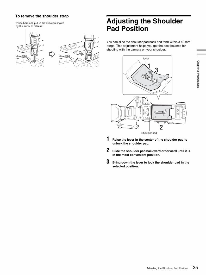
To remove the shoulder strap
Adjusting the Shoulder Pad Position
You can slide the shoulder pad back and forth within a 40 mm range. This adjustment helps you get the best balance for shooting with the camera on your shoulder.
1 Raise the lever in the center of the shoulder pad to unlock the shoulder pad.
2 Slide the shoulder pad backward or forward until it is in the most convenient position.
3 Bring down the lever to lock the shoulder pad in the selected position.
Press here and pull in the direction shown by the arrow to release.
Shoulder pad
lever
35Adjusting the Shoulder Pad Position

hapter3
36
Chapter 3 S
hooting
CShooting
Basic Procedure for Shooting
Note
When the HXCU-D70, CCU-D50/D50P Camera Control Unit or an external control device, such as an RCP-series Remote Control Panel, is connected, the white balance, black balance and shutter adjustments are controlled from the external device, and the controls on the camera are disabled.
For operations on the external control device, refer to the operating instructions or operation manual for the device.
1 Turn the camera on.
2 Set the FILTER knob and COLOR TEMP. button appropriately for the lighting conditions.
FILTER knob settings
1) Depth of field: This is the range over which the subject is sharply in focus.
From the viewpoint of the characteristics of lenses, shooting with the iris set in the range of F4 to F8 is generally recommended for good quality pictures. Set the filter select knob to bring the iris setting into that range. However, this may not apply when special composition is desired.
5600K settingThe 5600K ON/OFF function has been assigned to the COLOR TEMP. button at the factory.
3 Check the settings of the camera.• Settings of switches/control knobs• Settings in the OPERATION menu (page 54) and the
PAINT menu (page 59)• Electronic shutter setting (page 38)• Settings for the output signals from the camera
(page 42)• Flange focal length setting (page 30)
4 Adjust the eyepiece focus as well as the contrast and brightness of the viewfinder image.
For viewfinder settings, refer to the operation manual for the viewfinder.
5 If required, switch on the center marker and/or safety zone and zebra pattern in the viewfinder image, using OPERATION > VF MARKER (page 55) and OPERATION > ZEBRA (page 56) in the setup menu.
6 Check the sound system settings.• Microphone connections• Settings of the audio input select switch
7 Adjust the white balance and black balance (page 37).
8 Turn the focusing ring so that the subject is sharply in focus.
FILTER knob Lighting conditions
1 (Clear) Indoor shooting
2 (1/4 ND) Outdoor (cloudy or rainy) or indoor shooting when you wish to reduce the depth of field1)
3 (1/16 ND) Outdoor shooting in daytime
4 (1/64ND) Outdoor shooting when you wish to reduce the depth of field, or especially under bright outdoor ambient light
5600K Example of lighting conditions
OFF Indoor shooting under lighting with lower color temperature, such as a halogen or tungsten lamp
ON Outdoor shooting in daytime, or indoor shooting under lighting with higher color temperature
Basic Procedure for Shooting

Chapter 3 S
hooting
Adjustments and Settings
Changing the Video Format
1 Select MAINTENANCE > OUTPUT FORMAT in the setup menu (see page 66).
2 Turn the menu control knob to select the item to change, and press the knob.
3 Turn the menu control knob to change the setting, and press the knob.
Adjusting the Black Balance and the White Balance
To ensure excellent image quality when using this camera, conditions may require that both the black balance and the white balance be adjusted.Black balance and white balance adjustment values that are automatically set by the camera and the various settings are stored in the camera memory and retained even when the power is turned off.
Black balance adjustmentThe black balance will require adjustment in the following cases.• When the camera is used for the first time• When the camera has not been used for a long time• When the camera is used under conditions in which the
surrounding temperature has changed greatly• When the GAIN selector (L/M/H) values have been changed
by using OPERATION > SWITCH ASSIGN1 > GAIN switch in the setup menu (see page 57).
It is not usually necessary to adjust the black balance when using the camera after it has been off.
White balance adjustmentAlways readjust the white balance when the lighting conditions change.
Adjusting the Black BalanceIn automatic black balance mode, adjustments are performed in the following order: black set and black balance. Manual black balance adjustment can be selected from the setup menu.
For details of manual black balance adjustment, refer to the maintenance manual.
1 Set the OUTPUT/AUTO KNEE switch to CAM.
2 Push the WHT/BLK switch to BLK and release the switch.
The message “Executing...” appears during execution, and changes to “OK” when the adjustment finishes. Adjustment values are saved to memory automatically.
Notes
• During the black balance adjustment, the iris is automatically closed.
• During the black balance adjustment, the gain selection circuit is automatically activated so you may see flickering in the viewfinder, but this is not a fault.
If automatic black balance adjustment cannot be madeIf the black balance adjustment cannot be completed normally, an error message will appear for about three seconds in the viewfinder.If any error message is displayed, retry the black balance adjustment.If the error message occurs again, consult your Sony dealer or a Sony service representative.
Note
If the lens cable is not firmly connected to the LENS connector, it may not be possible to adjust the lens iris. If this happens, the black balance will be incorrect.
Adjusting the White Balance
1 Set the switches and selectors as shown below.• GAIN selector: L (set to a gain value that is as small as
possible) • OUTPUT/AUTO KNEE switch: CAM• WHITE BAL switch: A or B
2 Set the FILTER knob to suit the lighting conditions as follows.
3 Place a white test card under the same lighting conditions as for the subject to be shot and zoom up to it. Alternatively, any white object such as a cloth or a wall can be used.The absolute minimum white area is as follows.
Note
Make sure there are not bright spots in the rectangle.
Rectangle centered on the screen. The lengths of the sides are 70% of the length and width of the screen.
The white object must be within the rectangle and have an area of at least 10% of the screen.
37Adjustments and Settings
38
Chapter 3 S
hooting
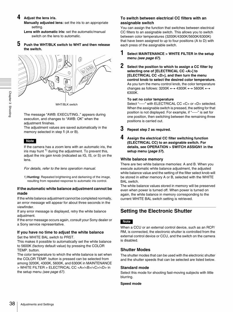
4 Adjust the lens iris.Manually adjusted lens: set the iris to an appropriate
setting.Lens with automatic iris: set the automatic/manual
switch on the lens to automatic.
5 Push the WHT/BLK switch to WHT and then release the switch.
The message “AWB: EXECUTING..” appears during execution, and changes to “AWB: OK” when the adjustment finishes.The adjustment values are saved automatically in the memory selected in step 1 (A or B).
Note
If the camera has a zoom lens with an automatic iris, the iris may hunt 1) during the adjustment. To prevent this, adjust the iris gain knob (indicated as IG, IS, or S) on the lens.
For details, refer to the lens operation manual.
1) Hunting: Repeated brightening and darkening of the image, resulting from repeated response to automatic iris control.
If the automatic white balance adjustment cannot be madeIf the white balance adjustment cannot be completed normally, an error message will appear for about three seconds in the viewfinder.If any error message is displayed, retry the white balance adjustment.If the error message occurs again, consult your Sony dealer or a Sony service representative.
If you have no time to adjust the white balanceSet the WHITE BAL switch to PRST.This makes it possible to automatically set the white balance to 5600K (factory default value) by pressing the COLOR TEMP. button.The color temperature to which the white balance is set when the COLOR TEMP. button is pressed can be selected from among 3200K, 4300K, 5600K, and 6300K in MAINTENANCE > WHITE FILTER > ELECTRICAL CC <A>/<B>/<C>/<D> in the setup menu (see page 67).
To switch between electrical CC filters with an assignable switchYou can assign the function that switches between electrical CC filters to an assignable switch. This allows you to switch between color temperatures (3200K/4300K/5600K/6300K) that have been assigned to up to four positions (A to D) with each press of the assignable switch.
1 Select MAINTENANCE > WHITE FILTER in the setup menu (see page 67).
2 Select the position to which to assign a CC filter by selecting one of [ELECTRICAL CC <A>] to [ELECTRICAL CC <D>], and then turn the menu control knob to select the desired color temperature.As you turn the menu control knob, the color temperature changes as follows: 3200K y 4300K y 5600K y 6300K.
To set no color temperatureSelect “-----” with ELECTRICAL CC <C> or <D> selected.When the assignable switch is pressed, the setting for that position is not displayed. For example, if “-----” is set for one position, then switching between the remaining three positions is carried out.
3 Repeat step 2 as required.
4 Assign the electrical CC filter switching function (ELECTRICAL CC) to an assignable switch. For details, see OPERATION > SWITCH ASSIGN1 in the setup menu (page 57).
White balance memoryThere are two white balance memories: A and B. When you execute automatic white balance adjustment, the adjusted white balance value and the setting of the filter select knob will be stored in either memory A or B, selected with the WHITE BAL switch.The white balance values stored in memory will be preserved even when power is turned off. When power is turned on again, the white balance in memory corresponding to the current WHITE BAL switch setting is retrieved.
Setting the Electronic Shutter
Note
When a CCU or an external control device, such as an RCP/RM, is connected, the electronic shutter is controlled from the external control device or CCU, and the switch on the camera is disabled.
Shutter ModesThe shutter modes that can be used with the electronic shutter and the shutter speeds that can be selected are listed below.
Standard modeSelect this mode for shooting fast-moving subjects with little blurring.
Speed mode
WHT/BLK switch
Adjustments and Settings
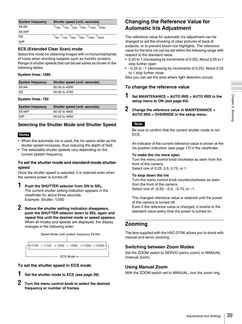
Chapter 3 S
hooting
ECS (Extended Clear Scan) modeSelect this mode for obtaining images with no horizontal bands of noise when shooting subjects such as monitor screens.Range of shutter speeds that can be set varies as shown in the following tables.
System lines: 1080
System lines: 720
Selecting the Shutter Mode and Shutter Speed
Notes
• When the automatic iris is used, the iris opens wider as the shutter speed increases, thus reducing the depth of field.
• The selectable shutter speeds vary depending on the current system frequency.
To set the shutter mode and standard-mode shutter speedOnce the shutter speed is selected, it is retained even when the camera power is turned off.
1 Push the SHUTTER selector from ON to SEL.The current shutter setting indication appears in the viewfinder for about three seconds.Example: Shutter: 1/250
2 Before the shutter setting indication disappears, push the SHUTTER selector down to SEL again and repeat this until the desired mode or speed appears.When all modes and speeds are displayed, the display changes in the following order.
To set the shutter speed in ECS mode
1 Set the shutter mode to ECS (see page 39).
2 Turn the menu control knob to select the desired frequency or number of frames.
Changing the Reference Value for Automatic Iris Adjustment
The reference value for automatic iris adjustment can be changed to aid the shooting of clear pictures of back-lit subjects, or to prevent blown-out highlights. The reference value for the lens iris can be set within the following range with respect to the standard value.• 0.25 to 1 (increasing by increments of 0.25): About 0.25 to 1
stop further open• –0.25 to –1 (decreasing by increments of 0.25): About 0.25
to 1 stop further closeAlso you can set the area where light detection occurs.
To change the reference value
1 Set MAINTENANCE > AUTO IRIS > AUTO IRIS in the setup menu to ON (see page 64).
2 Change the reference value in MAINTENANCE > AUTO IRIS > OVERRIDE in the setup menu.
Note
Be sure to confirm that the current shutter mode is not ECS.
An indicator of the current reference value is shown at the iris position indication (see page 17) in the viewfinder.
To make the iris more openTurn the menu control knob clockwise as seen from the front of the camera.Select one of 0.25, 0.5, 0.75, or 1.
To stop down the irisTurn the menu control knob counterclockwise as seen from the front of the camera.Select one of –0.25, –0.5, –0.75, or –1.
The changed reference value is retained until the power of the camera is turned off.Even if the reference value is changed, it reverts to the standard value every time the power is turned on.
Zooming
The lens supplied with the HXC-D70K allows you to shoot with manual and servo zooming.
Switching between Zoom ModesSet the ZOOM switch to SERVO (servo zoom) or MANUAL (manual zoom).
Using Manual ZoomWith the ZOOM switch set to MANUAL, turn the zoom ring.
System frequency Shutter speed (unit: seconds)
59.94i
59.94P
1/100, 1/125, 1/250, 1/500, 1/1000, 1/2000
50i
50P
1/60, 1/125, 1/250, 1/500, 1/1000, 1/2000
System frequency Shutter speed (unit: seconds)
59.94i 60.00 to 4300
50i 50.00 to 4700
System frequency Shutter speed (unit: seconds)
59.94P 60.02 to 4600
50P 50.03 to 4600
1/100 1/20001/10001/5001/2501/125
Speed Mode (with system frequency 59.94i)
ECS Mode
39Adjustments and Settings

40
Chapter 3 S
hooting
Using Servo ZoomWith the ZOOM switch set to SERVO, operate the power zoom lever. The current lens zoom position appears in the viewfinder, over the range 0 (wide-angle) to 99 (telephoto) (see page 17).Push to the W (wide) side when you want wide-angle, and push to the T (telephoto) side when you want telephoto. The zoom speed increases when you push the lever deeply, and decreases when you push less deeply.
Adjusting the Focus
The lens supplied with the HXC-D70K allows you to adjust the focus in the following three ways.
Full MF (full manual focus) modeThis mode supports focusing with the focus ring only.Without changing your grip, you can focus all the way from ∞ to the shortest shooting distance.
MF (manual focus) modeIn this mode, auto focus is enabled temporarily when you press the PUSH AF button.You can also use the MF * function (see page 40).
AF (auto focus) modeIn this mode, auto focus is always enabled.The focus ring and the PUSH AF button are also enabled.
Note
The lens is designed with an extra margin at the infinity position (∞), to compensate for focus drifting due to variations in temperature. When shooting a subject at infinity in MF or Full MF mode, check the picture in the viewfinder as you focus.
Adjusting in Full MF ModeWhen you slide the focus ring back (toward the camera), the focus mode becomes Full MF mode, in which all focus adjustments are manual.
Note
When you slide the focus ring back, the focus instantly moves to the mark position.
Focus by turning the focus ring while viewing the viewfinder.The distance indications on the ring are valid in Full MF mode. The distances where the picture is in focus correspond to absolute positions of the focus ring.
PeakingYou can turn the PEAKING knob on the viewfinder to use the peaking function. Edges are emphasized in the monitor picture, which facilitates manual focusing.The recorded video signals are not affected.
Adjusting in MF ModeWhen you slide the focus ring forward (toward the lens hood), and set the FOCUS switch to M (manual), the focus mode becomes MF mode, in which focus adjustments are manual but auto focus is available only when necessary.
Using the focus ringFocus by turning the focus ring while viewing the viewfinder.The distance indications on the ring are invalid in MF mode.
One-push auto focusPress the PUSH AF button. Auto focus is enabled temporarily (one-push auto focus).One-push auto focus ends when the subject is brought into focus.
MF * functionWhen the MF * function is on, auto focus starts when you stop adjusting with the focus ring, enabling fine adjustments with the subject at the center of the screen.Auto focusing by the MF * function ends when the fine adjustments end.
Adjusting in AF ModeWhen you slide the focus ring forward, and set the FOCUS switch to A (auto), the focus mode becomes AF mode, in which auto focus is always active.The distance indications on the ring are invalid in AF mode.
Focusing in AF modeIn AF mode, the camera monitors the video for changes, and starts auto focus whenever it detects a change. Auto focusing ends when the subject is in focus, but the auto focus function remains on standby.In AF mode, you can also start auto focusing by pressing the PUSH AF button or by turning the focus ring.
Using Macro ModeWhen the focus mode is MF or AF, you can set the MACRO switch to the ON side to enable macro mode. Macro mode allows you to focus over the range that includes the macro area.Macro mode is disabled in Full MF mode.
White line indicating the current distance
Focus ring
Distance indication
Adjustments and Settings
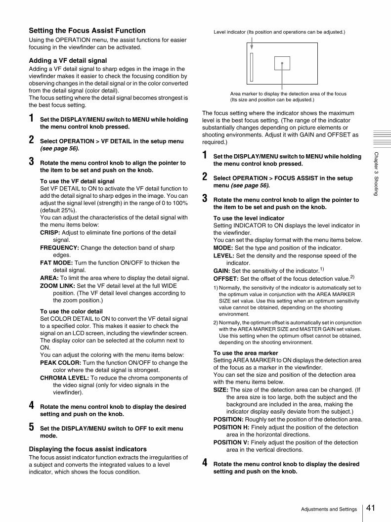
Chapter 3 S
hooting
Setting the Focus Assist FunctionUsing the OPERATION menu, the assist functions for easier focusing in the viewfinder can be activated.
Adding a VF detail signalAdding a VF detail signal to sharp edges in the image in the viewfinder makes it easier to check the focusing condition by observing changes in the detail signal or in the color converted from the detail signal (color detail).The focus setting where the detail signal becomes strongest is the best focus setting.
1 Set the DISPLAY/MENU switch to MENU while holding the menu control knob pressed.
2 Select OPERATION > VF DETAIL in the setup menu (see page 56).
3 Rotate the menu control knob to align the pointer to the item to be set and push on the knob.
To use the VF detail signalSet VF DETAIL to ON to activate the VF detail function to add the detail signal to sharp edges in the image. You can adjust the signal level (strength) in the range of 0 to 100% (default 25%).You can adjust the characteristics of the detail signal with the menu items below:CRISP: Adjust to eliminate fine portions of the detail
signal.FREQUENCY: Change the detection band of sharp
edges.FAT MODE: Turn the function ON/OFF to thicken the
detail signal.AREA: To limit the area where to display the detail signal.ZOOM LINK: Set the VF detail level at the full WIDE
position. (The VF detail level changes according to the zoom position.)
To use the color detailSet COLOR DETAIL to ON to convert the VF detail signal to a specified color. This makes it easier to check the signal on an LCD screen, including the viewfinder screen. The display color can be selected at the column next to ON.You can adjust the coloring with the menu items below:PEAK COLOR: Turn the function ON/OFF to change the
color where the detail signal is strongest.CHROMA LEVEL: To reduce the chroma components of
the video signal (only for video signals in the viewfinder).
4 Rotate the menu control knob to display the desired setting and push on the knob.
5 Set the DISPLAY/MENU switch to OFF to exit menu mode.
Displaying the focus assist indicatorsThe focus assist indicator function extracts the irregularities of a subject and converts the integrated values to a level indicator, which shows the focus condition.
The focus setting where the indicator shows the maximum level is the best focus setting. (The range of the indicator substantially changes depending on picture elements or shooting environments. Adjust it with GAIN and OFFSET as required.)
1 Set the DISPLAY/MENU switch to MENU while holding the menu control knob pressed.
2 Select OPERATION > FOCUS ASSIST in the setup menu (see page 56).
3 Rotate the menu control knob to align the pointer to the item to be set and push on the knob.
To use the level indicatorSetting INDICATOR to ON displays the level indicator in the viewfinder.You can set the display format with the menu items below.MODE: Set the type and position of the indicator.LEVEL: Set the density and the response speed of the
indicator.GAIN: Set the sensitivity of the indicator.1)
OFFSET: Set the offset of the focus detection value.2)
1) Normally, the sensitivity of the indicator is automatically set to the optimum value in conjunction with the AREA MARKER SIZE set value. Use this setting when an optimum sensitivity value cannot be obtained, depending on the shooting environment.
2) Normally, the optimum offset is automatically set in conjunction with the AREA MARKER SIZE and MASTER GAIN set values. Use this setting when the optimum offset cannot be obtained, depending on the shooting environment.
To use the area markerSetting AREA MARKER to ON displays the detection area of the focus as a marker in the viewfinder.You can set the size and position of the detection area with the menu items below.SIZE: The size of the detection area can be changed. (If
the area size is too large, both the subject and the background are included in the area, making the indicator display easily deviate from the subject.)
POSITION: Roughly set the position of the detection area.POSITION H: Finely adjust the position of the detection
area in the horizontal directions.POSITION V: Finely adjust the position of the detection
area in the vertical directions.
4 Rotate the menu control knob to display the desired setting and push on the knob.
Level indicator (Its position and operations can be adjusted.)
Area marker to display the detection area of the focus (Its size and position can be adjusted.)
41Adjustments and Settings

42
Chapter 3 S
hooting
5 Set the DISPLAY/MENU switch to OFF to exit menu mode.
Notes
• The level indicator and the effect area marker cannot be displayed simultaneously, whichever you set to ON later is preferentially displayed.
• The area marker and the aspect safety marker cannot be displayed simultaneously, whichever you set to ON later is preferentially displayed.
• When displaying the focus assist indicators, check that the flange focal length has been precisely adjusted.
See “Adjusting the Flange Focal Length” (page 30) for the flange focal length.
Setting the Camera Outputs
You can specify video signals directly output from the camera, with menu operations.
Note
The MAIN (camera picture), RET (return video), or VF (the same picture as that displayed in the viewfinder) setting is common to SD-SDI and VBS. Different signals cannot be output.
The menu pages used for the output settings have been registered to the USER menu at the factory.• <POWER SAVE> (U10)• <OUTPUT FORMAT> (U15)• <TEST OUT> (U16)• <DOWN CONVERTER> (U17)
Set the menu items on the above menu pages to the settings shown in the following tables.
For details on menu operations and the USER menu, see “Basic Menu Operations” (page 48).
Outputting the signal being shot (camera picture)The same textual information as that displayed in the viewfinder can be added to the output signal by setting CHARACTER to ON on the <SDI OUT> or <TEST OUT> page.
To output as HD-SDI
To output as SD-SDI
To output as VBS
Constantly outputting a return video• When a CCU is connected, one of the signals being
supplied to the CCU can be output from the camera.• The last selected return signal is output.
To output as HD-SDI
Outputting the same image as that in the viewfinderWith HD-SDI, you can obtain a signal that includes the same information as that being displayed in the viewfinder according to the settings for VF MARKER, CHARACTER, VF DETAIL, ZEBRA, etc. The ON/OFF or other settings for adding information are common to those for the viewfinder. The output is synchronized with switching among Y, R, G, and B or switching to a return signal.
To output as HD-SDI
To output as TEST OUT
Note
VF signal format (a Y signal only) output from the TEST OUT connector varies depending on which of the following viewfinders are connected to the VF connector (20-pin, round).No viewfinder: SD component (Y) signalDXF-C50WA viewfinder: HD component (Y) signalViewfinders other than DXF-C50WA: SD component (Y)
signal
Outputting a prompter signalThe VBS signal supplied to the PROMPTER connector of the CCU is output from the PROMPTER/GENLOCK connector of the camera.
Adjusting the Audio Level
When the camera is used with the HXCU-D70The input levels from audio sources connected to the AUDIO 1 IN and AUDIO 2 IN connectors can be adjusted using a remote control panel connected to the CCU or the CONFIGURATION menu on the CCU.When the audio input select switch is set to MIC, the level can be adjusted between 20 dB and 60 dB in steps of 10 dB.When the audio input select switch is set to LINE, the level cannot be adjusted.
Menu page Item Setting
<POWER SAVE> SDI OUT ACTIVE
<SDI OUT> OUTPUT MAIN
Menu page Item Setting
<POWER SAVE> SDI OUT ACTIVE
DOWN CONVERTER ACTIVE
<DOWN CONVERTER> OUTPUT SIGNAL MAIN
<SDI OUT> OUTPUT SD-SDI
Menu page Item Setting
<POWER SAVE> DOWN CONVERTER ACTIVE
<DOWN CONVERTER> OUTPUT SIGNAL MAIN
<TEST OUT> OUTPUT VBS
Menu page Item Setting
<POWER SAVE> SDI OUT ACTIVE
<SDI OUT> OUTPUT RET
Menu page Item Setting
<POWER SAVE> SDI OUT ACTIVE
<SDI OUT> OUTPUT VF
Menu page Item Setting
<POWER SAVE> DOWN CONVERTER ACTIVE
<TEST OUT> OUTPUT VF
Menu page Item Setting
Adjustments and Settings
Chapter 3 S
hooting
When the camera is used in standalone status or used with the CCU-D50/D50PThe input level from audio sources connected to the AUDIO 1 IN and AUDIO 2 IN connectors can be adjusted using the INTERCOM LEVEL control on the front panel.When the audio input select switch is set to MIC, the level can be adjusted between 20 dB and 60 dB in steps of 10 dB, using the INTERCOM LEVEL control.When the audio input select switch is set to LINE, the level cannot be adjusted.You can change the VR functions using OPERATION > VR ASSIGN in the setup menu (see page 57). Set the gain to avoid clipping the audio signal by monitoring the audio level meters and waveforms.
Using the flash band compensation function
Flash band artifacts are detected and compensated by using the flash band compensation function.Set MAINTENANCE > CIS COMP > FLASH BAND COMP (page 65) in the setup menu to on.• The flash band compensation function is available when the
shutter function is deactivated.• The flash band compensation function will be forcibly
switched from on to off while the shutter function is activated. The function turns on automatically after the shutter function becomes deactivated.
Notes
• While the flash band compensation function is set to on, video output from the camera is delayed by 1 field.
• Depending on the shooting conditions, flash band artifacts may not be detected and compensated properly.The function may not be performed depending on the following conditions:– Subject of shooting– Ambient lighting– Camera-subject distance/angle– Flash-subject distance/angle– Flash intensity– Light-emitting time– Multiple-flash for a shooting– Timing to flash for a shooting
• The flash band compensation function is activated when the brightness of the lower half of the image differs considerably from the upper half.Since the function may be inadvertently activated under certain shooting conditions, in which the brightness between the upper and lower half of the image differs markedly, be sure to use the function only for shooting footage exposed to flash light.
To reduce flash band artifactsIf flash band artifacts are detected using this function, the unit compensates them as follows.No compensation is performed when a flash extends to the entire screen (the brightness is not divided between the top and bottom of the image).
When the flash band effects appears in two framesStitches together the split-field flash frames, regenerating a single frame in which a flash extends entirely.
Notes
• The compensation is performed by reducing the brightness of flashes.
• Horizontal lines (low brightness line of pixels) may appear on the screen as a result of regeneration of the frame.
• When a moving subject is shot, images in the upper and lower parts of the screen may appear discontinuously or the subject may appear to be stationary for a moment.
• The flash band effect remains uncorrected when a flash extends from the lower lines of pixels.
Using the digital extender function
With this function, the central area of the screen is magnified twice.
1 Sets MAINTENANCE > POWER SAVE > D.EXTENDER (page 67) in the setup menu to ENABLE.
2 Select DIGITAL EXTENDER in OPERATION > SWITCH ASSIGN1 > ASSIGNABLE1/2/3 (in either of three) in the setup menu (page 57).
3 Press the ASSIGNABLE button you assigned the function to in step 2.The central area of the screen is magnified twice. Pressing the button again returns to the standard display mode.
Notes
• While MAINTENANCE > POWER SAVE > D.EXTENDER (page 67) in the setup menu is set to ENABLE, video output from the camera is delayed by 1 field.
• If both the flash band compensation function and digital extender function are used at the same time, video output from the camera is delayed by 2 fields.
43Adjustments and Settings

hapter4
44
Chapter 4 M
enu and Detailed S
ettings
CMenu and Detailed Settings
Setup Menu Organization and Levels
On this camera, settings are made in the setup menu, which appears in the viewfinder.
Setup Menu Organization
The setup menu consists of the following menus.
OPERATION menu
VF DISPLAY EX
D.EX
ZOOM
DISP
FOCUS
MODE
ND
CC
5600K
IRIS
GAIN
SHUTT
WHITE
BATT
RETURN
TALK
AUDIO
MESSAG
TALLY
VF DISPLAY 2 FRONT/REAR VR
"!" IND ND
CC
WHITE
5600K
GAIN
SHUTT
EXT
FORMAT
VF MARKER MARKER
CENTER
SAFETY ZONE
EFFECT
ASPECT
MASK
SAFETY
VF DETAIL VF DETAIL
CRISP
FREQUENCY
FAT MODE
AREA
ZOOM LINK
COLOR DETAIL
PEAK COLOR
CHROMA LEVEL
FOCUS ASSIST INDICATOR
MODE
LEVEL
GAIN
OFFSET
AREA MARKER
SIZE
POSITION
POSITION H
POSITION V
ZEBRA ZEBRA
ZEBRA1 LEVEL
WIDTH
ZEBRA2
CURSOR CURSOR
BOX/CROSS
H POSITION
V POSITION
WIDTH
HEIGHT
VF OUT VF OUT
VF COLOR
SWITCH ASSIGN1 GAIN
ASSIGNABLE 1
ASSIGNABLE 2
ASSIGNABLE 3
ASSIGN CTEMP
Setup Menu Organization and Levels

Chapter 4 M
enu and Detailed S
ettings
PAINT menu RE.ROTATION
SWITCH ASSIGN2 LENS VTR S/S
FRONT RET2
VR ASSIGN FRONT VR
REAR VR
HEAD SET INTERCOM MIC
LEVEL
POWER
UNBAL
INTERCOM LEVEL SIDE TONE
PGM MIX LEVEL
EARPHONE EARPHONE RECEIVE SELECT
INTERCOM
AUDIO 1
AUDIO 2
SDI IN 1
SDI IN 2
EARPHONE LEVEL
OPERATOR FILE READ (MS t CAM)
WRITE (CAM t MS)
PRESET
FILE ID
CAM CODE
DATE
LENS FILE FILE
CENTER MARKER
H POS
V POS
STORE
SW STATUS FLARE
GAMMA
BLK GAM
KNEE
WHT CLIP
DETAIL
LVL DEP
SKIN DTL
MATRIX
VIDEO LEVEL WHITE
BLACK
FLARE
GAMMA
V MOD
FLARE
V MOD
D. SHAD
TEST
COLOR TEMP WHITE
AUTO WHITE BALANCE
COLOR TEMP
BALANCE
ATW
SPEED
MASTER
GAMMA LEVEL
COARSE
TABLE
GAMMA
TEST
BLACK GAMMA LEVEL
RANGE
TEST
SATURATION SATURATION
LOW KEY SAT
RANGE
TEST
KNEE K POINT
K SLOPE
KNEE
KNEE MAX
KNEE SAT
AUTO KNEE
POINT LIMIT
SLOPE
ABS
WHITE CLIP W CLIP
ABS
DETAIL 1 DETAIL
LEVEL
LIMITER [M]
[WHT]
[BLK]
CRISP
LVL DEP
ABS
45Setup Menu Organization and Levels

46
Chapter 4 M
enu and Detailed S
ettings
MAINTENANCE menuDETAIL 2 H/V RATIO
FREQ
MIX RATIO
KNEE APT
ABS
SKIN DETAIL SKIN DTL
SKIN GATE
AUTO HUE
PHASE
WIDTH
SAT
LEVEL
ABS
USER MATRIX R-G
R-B
G-R
G-B
B-R
B-G
MATRIX
PRESET
USER
MULTI
ADAPTIVE MATRIX
MULTI MARTRIX PHASE
HUE
SAT
ALL CLEAR
GATE
MATRIX
PRESET
USER
MULTI
SHUTTER SHUTTER
ECS FREQ
NOISE SUP NOISE SUP
SCENE FILE 1
2
3
4
5
STORE
STANDARD
READ (MS t CAM)
WRITE (CAM t MS)
FILE ID
CAM CODE
DATE
AUTO SETUP AUTO BLACK
AUTO WHITE
AUTO LEVEL
AUTO WHITE SHADING
AUTO BLACK SHADING
TEST
WHITE SHADING V SAW
V PARA
H SAW
H PARA
WHITE
AUTO WHITE SHADING
WHITE SHAD MODE
BLACK SHADING V SAW
V PARA
H SAW
H PARA
BLK SET
BLACK
MASTER GAIN
AUTO BLACK SHADING
AUTO IRIS AUTO IRIS
WINDOW
OVERRIDE
IRIS LEVEL
APL RATIO
IRIS GAIN
IRIS CLOSE
CIS COMP FLICKER REDUCE
MODE
FREQ
FLASH BAND COMP
COMP
AUDIO MIC GAIN
AUDIO 1
AUDIO 2
CCZ OUT
AUDIO 1
AUDIO 2
TEST TONE
CALL/TALLY CCU CALL
CAM CALL
OUTPUT FORMAT CURRENT
ACTIVE LINE
COUNTRY
DOWN CONVERTER OUTPUT SIGNAL
SETTING
ASPECT
BARS MODE
SD CCS
SD DETAIL
CRISP
LVL DEP
H/V RATIO
H DTL FREQ
Setup Menu Organization and Levels

Chapter 4 M
enu and Detailed S
ettings
FILE menuTEST OUT OUTPUT
VBS-OUT
CHARACTER
SYNC-OUT
V-PHASE
H PHASE
SDI OUT OUTPUT
CHARACTER
CCZ OUT OUTPUT
POWER SAVE SDI OUT
DOWN CONVERTER
D.EXTENDER
GENLOCK REFERENCE
GENLOCK
STATUS
FORMAT
V PHASE
H PHASE
H FINE
SC PHASE
DATE DATE/TIME
BATTERY ALARM BEFORE END
END
WHITE FILTER ELECTRICAL CC <A>
ELECTRICAL CC <B>
ELECTRICAL CC <C>
ELECTRICAL CC <D>
OTHERS 1 CAM BARS
V DTL CREATION
DTL H/V MODE
TEST2 MODE
WHITE SETUP MODE
ALAC
AUTO FLANGE BACK
HDSDI REMOTE I/F
OTHERS 2 DATE TYPE
F NO. DISP
AF DETECT AREA
EXT RETURN EXT RETURN
SD ASPECT
OPERATOR FILE READ (MS t CAM)
WRITE (CAM t MS)
PRESET
STORE PRESET FILE
FILE ID
CAM MODE
DATE
SCENE FILE 1
2
3
4
5
STORE
STANDARD
READ (MS t CAM)
WRITE (CAM t MS)
FILE ID
CAM CODE
DATE
REFERECNE STORE FILE
STANDARD
ALL PRESET
READ (MS t CAM)
WRITE (CAM t MS)
FILE ID
CAM CODE
DATE
LENS FILE STORE FILE
No.
NAME
F NO
CENTER MARKDER
H POS
V POS
STORE
FILE CLEAR PRESET OPERATOR
REFERENCE (ALL)
10 SEC CLEAR
ALL MENU PRESET
M.S. FORMAT
47Setup Menu Organization and Levels
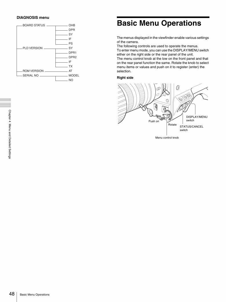
48
Chapter 4 M
enu and Detailed S
ettings
DIAGNOSIS menu
Basic Menu Operations
The menus displayed in the viewfinder enable various settings of the camera.The following controls are used to operate the menus.To enter menu mode, you can use the DISPLAY/MENU switch either on the right side or the rear panel of the unit. The menu control knob at the low on the front panel and that on the rear panel function the same. Rotate the knob to select menu items or values and push on it to register (enter) the selection.
Right side
BOARD STATUS OHB
DPR
SY
IF
PS
PLD VERSION SY
DPR1
DPR2
IF
TX
ROM VERSION AT
SERIAL NO MODEL
NO
Menu control knob
STATUS/CANCEL switch
DISPLAY/MENU switchPush on
Rotate
Basic Menu Operations
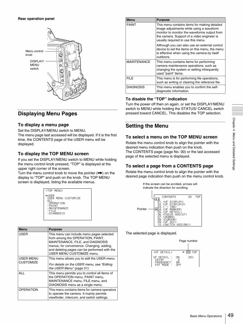
Chapter 4 M
enu and Detailed S
ettings
Rear operation panel
Displaying Menu Pages
To display a menu pageSet the DISPLAY/MENU switch to MENU.The menu page last accessed will be displayed. If it is the first time, the CONTENTS page of the USER menu will be displayed.
To display the TOP MENU screenIf you set the DISPLAY/MENU switch to MENU while holding the menu control knob pressed, “TOP” is displayed at the upper right corner of the screen.Turn the menu control knob to move the pointer (,) on the display to “TOP” and push on the knob. The TOP MENU screen is displayed, listing the available menus.
To disable the “TOP” indicationTurn the power off then on again, or set the DISPLAY/MENU switch to MENU while holding the STATUS/ CANCEL switch pressed toward CANCEL. This disables the TOP selection.
Setting the Menu
To select a menu on the TOP MENU screenRotate the menu control knob to align the pointer with the desired menu indication then push on the knob.The CONTENTS page (page No. 00) or the last accessed page of the selected menu is displayed.
To select a page from a CONTENTS pageRotate the menu control knob to align the pointer with the desired page indication then push on the menu control knob.
The selected page is displayed.Menu Purpose
USER This menu can include menu pages selected from among the OPERATION, PAINT, MAINTENANCE, FILE, and DIAGNOSIS menus, for convenience. Changing, adding, and deleting pages can be performed with the USER MENU CUSTOMIZE menu.
USER MENU CUSTOMIZE
This menu allows you to edit the USER menu.
For details on the USER menu, see “Editing the USER Menu” (page 51).
ALL This menu permits you to control all items of the OPERATION menu, PAINT menu, MAINTENANCE menu, FILE menu, and DIAGNOSIS menu as a single menu.
OPERATION This menu contains items for camera operators to operate the camera. It mainly permits viewfinder, intercom, and switch settings.
Menu control knob
DISPLAY/MENU switch
<TOP MENU>
USER
USER MENU CUSTOMIZE
ALL
OPERATION
PAINT
MAINTENANCE
FILE
DIAGNOSIS
PAINT This menu contains items for making detailed image adjustments while using a waveform monitor to monitor the waveforms output from the camera. Support of a video engineer is usually required to use this menu.
Although you can also use an external control device to set the items on this menu, the menu is effective when using the camera by itself outdoors.
MAINTENANCE This menu contains items for performing camera maintenance operations, such as changing the system or setting infrequently used “paint” items.
FILE This menu is for performing file operations, such as writing or clearing the reference file.
DIAGNOSIS This menu enables you to confirm the self-diagnostic information.
Menu Purpose
CONTENTS 00 TOP
01.<VF DISPLAY>
02.<VF DISPLAY2>
03.<'!'IND>
04.<VF MARKER>
05.<VF DETAIL>
06.<FOCUS ASSIST>
07.<ZEBRA>
08.<CURSOR>
09.<VF OUT>
10.<SWITCH ASSIGN1>
If the screen can be scrolled, arrows will indicate the direction for scrolling.
Pointer
<VF DETAIL> 05 TOP
VF DETAIL : ON 25%
CRISP : 0
FREQUENCY: 9M
FAT MODE : OFF
FLICKER OFF
Page number
49Basic Menu Operations

50
Chapter 4 M
enu and Detailed S
ettings
To change the displayed page
1 Check that the pointer is located at the left of the page number then push on the menu control knob.The pointer will change to a flashing question mark.
2 Rotate the menu control knob to flip through the pages, and push on the knob when the desired page is displayed.The question mark will change back to the pointer, and operations with the displayed page are enabled.
To return to the TOP MENU screenAlign the pointer with “TOP” at the top right of the menu page then push on the menu control knob.
To set the Menu ItemsIf a question mark is flashing at the left of the page number, push on the menu control knob to change it to the pointer. Operation on the displayed page is enabled.
1 Align the pointer with the desired item, then push on the menu control knob.The pointer will change to a flashing question mark.
2 Rotate the menu control knob to change the setting value.When the knob is rotated quickly, the values will change quickly; when rotated slowly, the values will change slowly.
To reset a changed valueIf you press the STATUS/ CANCEL switch toward CANCEL before pushing on the menu control knob, the setting will be returned to its previous value.
To interrupt settingsSet the DISPLAY/MENU switch to OFF to turn off the menu screen display. The setting operation can be restarted by setting the DISPLAY/MENU switch back to MENU.
3 Push on the menu control knob.The question mark will change back to the pointer, and the new setting will be registered.
4 To change other setting items on the same menu page, repeat steps 1 through 3.
To specify a character stringWhen you press the menu control knob with the pointer pointing to an item for which a character string, such as a file ID, is to be specified, a cursor and the list of selectable characters are displayed.The displayed cursor can be moved by rotating the menu control knob.
1 Set the cursor to the position where you wish enter a character, then push on the menu control knob.Another cursor appears on the character list.
2 Set the cursor to the character to be entered and push on the menu control knob.Repeat steps 1 and 2.• By selecting INS on the line below the character list, you
can enter a space at the cursor position.• Selecting DEL deletes the character at the cursor
position.• You can return to step 1 without changing the character
by selecting RET.• If you enter the permitted maximum number of
characters (up to the stop mark at the right end of the line), the cursor moves to ESC on the line below the character list.
3 Select END and push on the menu control knob.The new string you have set is registered.
To restore the previous stringSelect ESC and push on the menu control knob.
To return a menu item to its standard valueSelect the menu item to be returned to its standard value then hold the menu control knob pressed for 3 seconds while the pointer is displayed.If “10 SEC CLEAR” has been set to ON in FILE > FILE CLEAR in the setup menu (see page 71), you can return the setting in the reference file for the item being selected to the factory-set value by holding the menu control knob pressed for another 10 seconds.
To end menu operationsSet the DISPLAY/MENU switch to OFF.
<VF DETAIL> ? 05 TOP
VF DETAIL : ON 25%
CRISP : 0
FREQUENCY: 9M
FAT MODE : OFF
FLICKER OFF
flash
<VF DETAIL> 05 TOP
VF DETAIL : ON 25%
CRISP : 0
FREQUENCY: 9M
FAT MODE : OFF
Basic Menu Operations
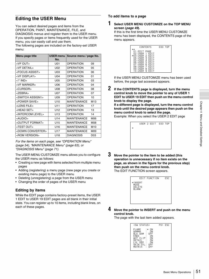
Chapter 4 M
enu and Detailed S
ettings
Editing the USER Menu
You can select desired pages and items from the OPERATION, PAINT, MAINTENANCE, FILE, and DIAGNOSIS menus and register them to the USER menu. If you specify pages or items frequently used for the USER menu, you can easily call and use them.The following pages are included on the factory-set USER menu:
For the items on each page, see “OPERATION Menu” (page 54), “MAINTENANCE Menu” (page 63), or “DIAGNOSIS Menu” (page 71).
The USER MENU CUSTOMIZE menu allows you to configure the USER menu as follows:• Creating a new page with items selected from multiple menu
pages• Adding (registering) a menu page (new page you create or
existing menu page) to the USER menu• Deleting (unregistering) a page from the USER menu• Changing the order of pages of the USER menu
Editing by itemsWhile the EDIT page contains factory-preset items, the USER 1 EDIT to USER 19 EDIT pages are all blank in their initial state. You can register up to 10 items, including blank lines, on each of these pages.
To add items to a page
1 Select USER MENU CUSTOMIZE on the TOP MENU screen (page 49).If this is the first time the USER MENU CUSTOMIZE menu has been displayed, the CONTENTS page of the menu appears.
If the USER MENU CUSTOMIZE menu has been used before, the page last accessed appears.
2 If the CONTENTS page is displayed, turn the menu control knob to move the pointer to any of USER 1 EDIT to USER 19 EDIT then push on the menu control knob to display the page.If a different page is displayed, turn the menu control knob until the desired page appears then push on the menu control knob to select the page.Example: When you select the USER 2 EDIT page
3 Move the pointer to the item to be added (this operation is unnecessary if no item exists on the page, as shown in the figure for the previous step) then push on the menu control knob.The EDIT FUNCTION screen appears.
4 Move the pointer to INSERT and push on the menu control knob.The page with the last item added appears.
Menu page title USER menu No.
Source menu / page No.
<VF OUT> U01 OPERATION 09
<VF DETAIL> U02 OPERATION 05
<FOCUS ASSIST> U03 OPERATION 06
<VF DISPLAY> U04 OPERATION 01
<‘!’ IND> U05 OPERATION 03
<VF MARKER> U06 OPERATION 04
<CURSOR> U08 OPERATION 08
<ZEBRA> U07 OPERATION 07
<SWITCH ASSIGN1> U09 OPERATION 10
<POWER SAVE> U10 MAINTENANCE M13
<LENS FILE> U11 OPERATION 17
<HEAD SET> U12 OPERATION 13
<INTERCOM LEVEL> U13 OPERATION 14
<AUDIO> U14 MAINTENANCE M06
<OUTPUT FORMAT> U15 MAINTENANCE M08
<TEST OUT> U16 MAINTENANCE M10
<DOWN CONVERTER> U17 MAINTENANCE M09
<ROM VERSION> U18 DIAGNOSIS D03
CONTENTS E00
xx
01.EDIT PAGE
02.USER 1 EDITc03.USER 2 EDIT
04.USER 3 EDIT
05.USER 4 EDIT
06.USER 5 EDIT
07.USER 6 EDIT
08.USER 7 EDIT
09.USER 8 EDIT
10.USER 9 EDIT
TOP
USER 2 EDIT E03
c
TOP
EDIT FUNCTION
cINSERT
MOVE
DELETE
BLANK
ESC
<SW STATUS> P01
FLARE :c ON
GAMMA : ON
BLK GAM : OFF
KNEE : ON
WHT CLIP: ON
DETAIL : ON
LVL DEP : ON
SKIN DTL: OFF
MATRIX : OFF
ESC
51Basic Menu Operations

52
Chapter 4 M
enu and Detailed S
ettings
5 Add the items.
1 Turn the menu control knob until the page that has the desired items appears, then push on the menu control knob.
2 Turn the menu control knob to move the pointer to the desired item, then push on the menu control knob
The USER 2 EDIT page appears again, displaying the newly added item.
6 Add the remaining items by repeating steps 3 to 5.You can add up to 10 items on one page.
To change the order of items on a page
1 Move the pointer to the item to be moved then push on the menu control knob.The EDIT FUNCTION screen appears.
2 Select MOVE then push on the menu control knob.The previously displayed page appears again.
3 Move the pointer to the position where you wish to move the item then push on the menu control knob.
The item selected in step 1 moves to the position that you selected in step 3.In the above example, ASSIGNABLE1 is moved to the top, and the other items are moved down one line.
To delete items from a page
1 Move the pointer to the item to be deleted then push on the menu control knob.The EDIT FUNCTION screen appears.
2 Select DELETE and push on the menu control knob.The previously displayed page appears again, and the message “DELETE OK? YESbNO” appears.
3 To delete, turn the menu control knob to move the pointer to YES and push on the menu control knob.
To insert a blank line
1 Move the pointer to the item above which you wish to insert a blank line.The EDIT FUNCTION screen appears.
2 Select BLANK then push on the menu control knob.The previously displayed page appears again, and a blank line is inserted above the specified item.
Note
You cannot insert a blank line on a page where 10 items have already been registered.
Editing by pagesYou can add a page to the USER menu, delete a page from the USER menu, or replace pages, using the EDIT PAGE of the USER MENU CUSTOMIZE menu.
To add a page
1 Select USER MENU CUSTOMIZE on the TOP MENU screen.If this is the first time the USER MENU CUSTOMIZE menu has been displayed, the CONTENTS page of the menu appears. If the menu has been used before, the page last accessed appears.
2 If the CONTENTS page is displayed, turn the menu control knob to move the pointer to EDIT PAGE then push on the menu control knob to display the EDIT PAGE screen. If a different page is displayed, turn the menu control knob until the EDIT PAGE screen appears then push on the menu control knob to select the page.
3 Move the pointer to the position where you wish to add the page then push on the menu control knob.The EDIT FUNCTION screen appears.
4 Select INSERT then push on the menu control knob.The selection screen appears.
5 Move the pointer to the desired page then push on the menu control knob.This adds the number and name of the selected page above the item selected in step 3.
To cancel addition of a pageBefore pushing the menu control knob in step 5, turn the menu control knob to move the pointer to ESC at the top right of the screen then push on the menu control knob.The EDIT PAGE screen appears again.
ITEM MOVE
xx
cVF OUT : COLOR
VF DETAIL : OFF
MARKER : ON
CURSOR : OFF
ZEBRA SW : OFF
: 1zASSIGNABLE1 : OFF
ESC
EDIT PAGE E01
xx
01.<VF OUT>c02.<VF DETAIL>
03.<FOCUS ASSIST>
04.<VF DISPLAY>
05.<'!' IND>
06.<VF MARKER>
07.<CURSOR>
08.<ZEBRA>
09.<SWITCH ASSIGN1>
10.<SWITCH ASSIGN2>
TOP
CONTENTS
xx
c01.USER 1
02.USER 2
03.USER 3
04.USER 4
05.USER 5
06.USER 6
07.USER 7
08.USER 8
09.USER 9
10.USER 10
ESC
Basic Menu Operations
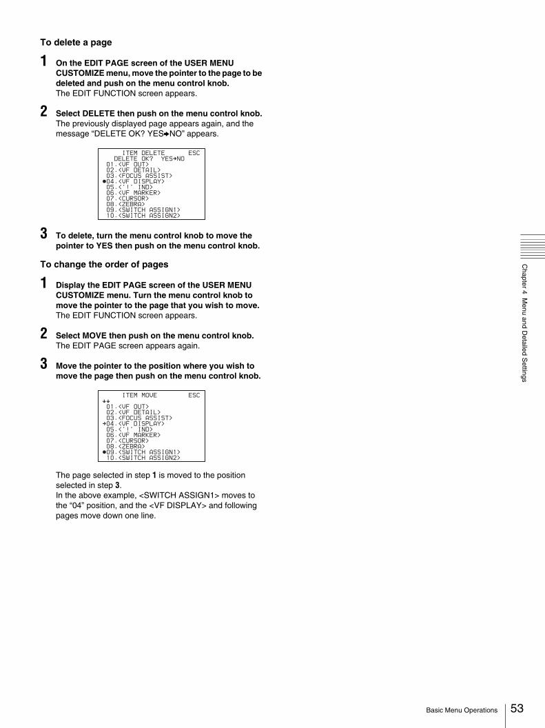
Chapter 4 M
enu and Detailed S
ettings
To delete a page
1 On the EDIT PAGE screen of the USER MENU CUSTOMIZE menu, move the pointer to the page to be deleted and push on the menu control knob.The EDIT FUNCTION screen appears.
2 Select DELETE then push on the menu control knob.The previously displayed page appears again, and the message “DELETE OK? YESbNO” appears.
3 To delete, turn the menu control knob to move the pointer to YES then push on the menu control knob.
To change the order of pages
1 Display the EDIT PAGE screen of the USER MENU CUSTOMIZE menu. Turn the menu control knob to move the pointer to the page that you wish to move.The EDIT FUNCTION screen appears.
2 Select MOVE then push on the menu control knob.The EDIT PAGE screen appears again.
3 Move the pointer to the position where you wish to move the page then push on the menu control knob.
The page selected in step 1 is moved to the position selected in step 3.In the above example, <SWITCH ASSIGN1> moves to the “04” position, and the <VF DISPLAY> and following pages move down one line.
ITEM DELETE
DELETE OK? YEScNO
01.<VF OUT>
02.<VF DETAIL>
03.<FOCUS ASSIST>z04.<VF DISPLAY>
05.<'!' IND>
06.<VF MARKER>
07.<CURSOR>
08.<ZEBRA>
09.<SWITCH ASSIGN1>
10.<SWITCH ASSIGN2>
ESC
ITEM MOVE
xx
01.<VF OUT>
02.<VF DETAIL>
03.<FOCUS ASSIST>c04.<VF DISPLAY>
05.<'!' IND>
06.<VF MARKER>
07.<CURSOR>
08.<ZEBRA>z09.<SWITCH ASSIGN1>
10.<SWITCH ASSIGN2>
ESC
53Basic Menu Operations
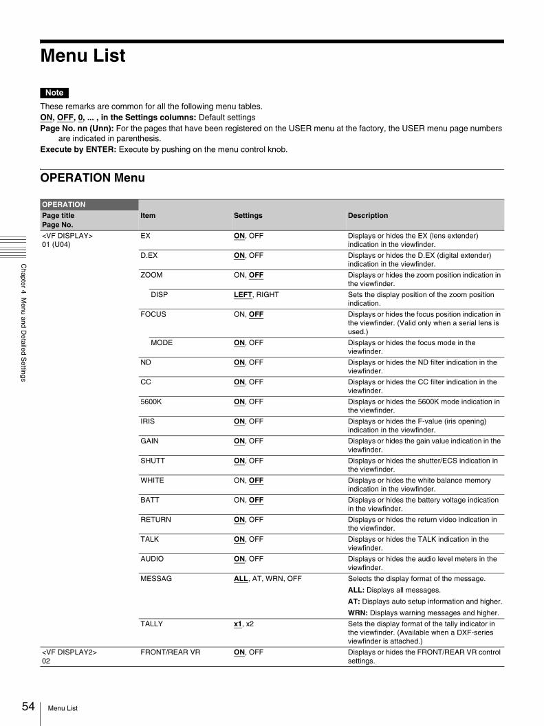
54
Chapter 4 M
enu and Detailed S
ettings
Menu List
Note
These remarks are common for all the following menu tables.ON, OFF, 0, ... , in the Settings columns: Default settingsPage No. nn (Unn): For the pages that have been registered on the USER menu at the factory, the USER menu page numbers
are indicated in parenthesis.Execute by ENTER: Execute by pushing on the menu control knob.
OPERATION Menu
OPERATION
Page titlePage No.
Item Settings Description
<VF DISPLAY> 01 (U04)
EX ON, OFF Displays or hides the EX (lens extender) indication in the viewfinder.
D.EX ON, OFF Displays or hides the D.EX (digital extender) indication in the viewfinder.
ZOOM ON, OFF Displays or hides the zoom position indication in the viewfinder.
DISP LEFT, RIGHT Sets the display position of the zoom position indication.
FOCUS ON, OFF Displays or hides the focus position indication in the viewfinder. (Valid only when a serial lens is used.)
MODE ON, OFF Displays or hides the focus mode in the viewfinder.
ND ON, OFF Displays or hides the ND filter indication in the viewfinder.
CC ON, OFF Displays or hides the CC filter indication in the viewfinder.
5600K ON, OFF Displays or hides the 5600K mode indication in the viewfinder.
IRIS ON, OFF Displays or hides the F-value (iris opening) indication in the viewfinder.
GAIN ON, OFF Displays or hides the gain value indication in the viewfinder.
SHUTT ON, OFF Displays or hides the shutter/ECS indication in the viewfinder.
WHITE ON, OFF Displays or hides the white balance memory indication in the viewfinder.
BATT ON, OFF Displays or hides the battery voltage indication in the viewfinder.
RETURN ON, OFF Displays or hides the return video indication in the viewfinder.
TALK ON, OFF Displays or hides the TALK indication in the viewfinder.
AUDIO ON, OFF Displays or hides the audio level meters in the viewfinder.
MESSAG ALL, AT, WRN, OFF Selects the display format of the message.
ALL: Displays all messages.
AT: Displays auto setup information and higher.
WRN: Displays warning messages and higher.
TALLY x1, x2 Sets the display format of the tally indicator in the viewfinder. (Available when a DXF-series viewfinder is attached.)
<VF DISPLAY2>02
FRONT/REAR VR ON, OFF Displays or hides the FRONT/REAR VR control settings.
Menu List
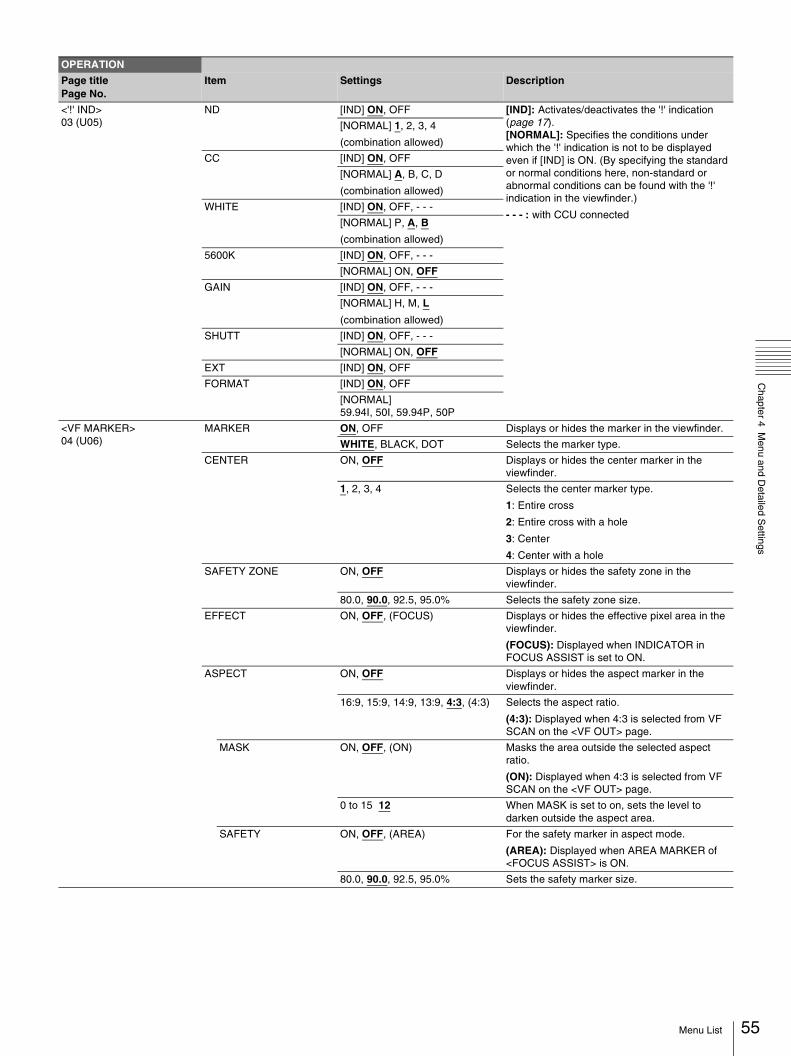
Chapter 4 M
enu and Detailed S
ettings
<'!' IND> 03 (U05)
ND [IND] ON, OFF [IND]: Activates/deactivates the '!' indication (page 17). [NORMAL]: Specifies the conditions under which the '!' indication is not to be displayed even if [IND] is ON. (By specifying the standard or normal conditions here, non-standard or abnormal conditions can be found with the '!' indication in the viewfinder.)
- - - : with CCU connected
[NORMAL] 1, 2, 3, 4
(combination allowed)
CC [IND] ON, OFF
[NORMAL] A, B, C, D
(combination allowed)
WHITE [IND] ON, OFF, - - -
[NORMAL] P, A, B
(combination allowed)
5600K [IND] ON, OFF, - - -
[NORMAL] ON, OFF
GAIN [IND] ON, OFF, - - -
[NORMAL] H, M, L
(combination allowed)
SHUTT [IND] ON, OFF, - - -
[NORMAL] ON, OFF
EXT [IND] ON, OFF
FORMAT [IND] ON, OFF
[NORMAL] 59.94I, 50I, 59.94P, 50P
<VF MARKER> 04 (U06)
MARKER ON, OFF Displays or hides the marker in the viewfinder.
WHITE, BLACK, DOT Selects the marker type.
CENTER ON, OFF Displays or hides the center marker in the viewfinder.
1, 2, 3, 4 Selects the center marker type.
1: Entire cross
2: Entire cross with a hole
3: Center
4: Center with a hole
SAFETY ZONE ON, OFF Displays or hides the safety zone in the viewfinder.
80.0, 90.0, 92.5, 95.0% Selects the safety zone size.
EFFECT ON, OFF, (FOCUS) Displays or hides the effective pixel area in the viewfinder.
(FOCUS): Displayed when INDICATOR in FOCUS ASSIST is set to ON.
ASPECT ON, OFF Displays or hides the aspect marker in the viewfinder.
16:9, 15:9, 14:9, 13:9, 4:3, (4:3) Selects the aspect ratio.
(4:3): Displayed when 4:3 is selected from VF SCAN on the <VF OUT> page.
MASK ON, OFF, (ON) Masks the area outside the selected aspect ratio.
(ON): Displayed when 4:3 is selected from VF SCAN on the <VF OUT> page.
0 to 15 12 When MASK is set to on, sets the level to darken outside the aspect area.
SAFETY ON, OFF, (AREA) For the safety marker in aspect mode.
(AREA): Displayed when AREA MARKER of <FOCUS ASSIST> is ON.
80.0, 90.0, 92.5, 95.0% Sets the safety marker size.
OPERATION
Page titlePage No.
Item Settings Description
55Menu List
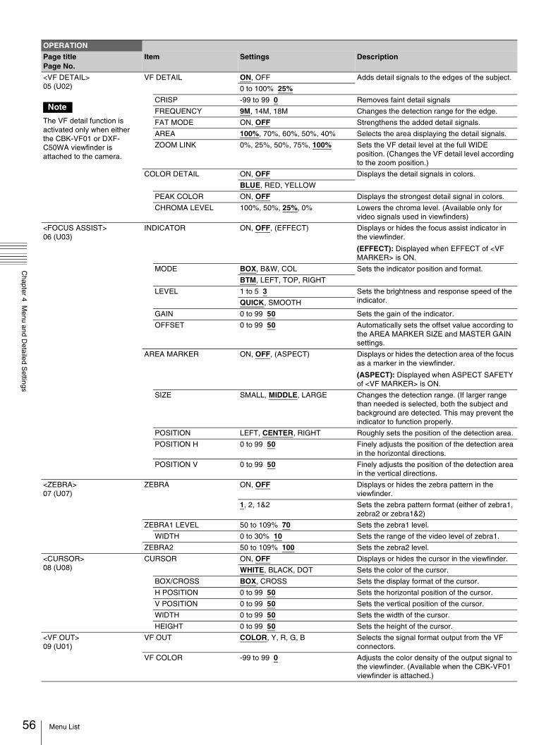
56
Chapter 4 M
enu and Detailed S
ettings
<VF DETAIL> 05 (U02)
Note
The VF detail function is activated only when either the CBK-VF01 or DXF-C50WA viewfinder is attached to the camera.
VF DETAIL ON, OFF Adds detail signals to the edges of the subject.
0 to 100% 25%
CRISP -99 to 99 0 Removes faint detail signals
FREQUENCY 9M, 14M, 18M Changes the detection range for the edge.
FAT MODE ON, OFF Strengthens the added detail signals.
AREA 100%, 70%, 60%, 50%, 40% Selects the area displaying the detail signals.
ZOOM LINK 0%, 25%, 50%, 75%, 100% Sets the VF detail level at the full WIDE position. (Changes the VF detail level according to the zoom position.)
COLOR DETAIL ON, OFF Displays the detail signals in colors.
BLUE, RED, YELLOW
PEAK COLOR ON, OFF Displays the strongest detail signal in colors.
CHROMA LEVEL 100%, 50%, 25%, 0% Lowers the chroma level. (Available only for video signals used in viewfinders)
<FOCUS ASSIST> 06 (U03)
INDICATOR ON, OFF, (EFFECT) Displays or hides the focus assist indicator in the viewfinder.
(EFFECT): Displayed when EFFECT of <VF MARKER> is ON.
MODE BOX, B&W, COL Sets the indicator position and format.
BTM, LEFT, TOP, RIGHT
LEVEL 1 to 5 3 Sets the brightness and response speed of the indicator.QUICK, SMOOTH
GAIN 0 to 99 50 Sets the gain of the indicator.
OFFSET 0 to 99 50 Automatically sets the offset value according to the AREA MARKER SIZE and MASTER GAIN settings.
AREA MARKER ON, OFF, (ASPECT) Displays or hides the detection area of the focus as a marker in the viewfinder.
(ASPECT): Displayed when ASPECT SAFETY of <VF MARKER> is ON.
SIZE SMALL, MIDDLE, LARGE Changes the detection range. (If larger range than needed is selected, both the subject and background are detected. This may prevent the indicator to function properly.
POSITION LEFT, CENTER, RIGHT Roughly sets the position of the detection area.
POSITION H 0 to 99 50 Finely adjusts the position of the detection area in the horizontal directions.
POSITION V 0 to 99 50 Finely adjusts the position of the detection area in the vertical directions.
<ZEBRA> 07 (U07)
ZEBRA ON, OFF Displays or hides the zebra pattern in the viewfinder.
1, 2, 1&2 Sets the zebra pattern format (either of zebra1, zebra2 or zebra1&2)
ZEBRA1 LEVEL 50 to 109% 70 Sets the zebra1 level.
WIDTH 0 to 30% 10 Sets the range of the video level of zebra1.
ZEBRA2 50 to 109% 100 Sets the zebra2 level.
<CURSOR> 08 (U08)
CURSOR ON, OFF Displays or hides the cursor in the viewfinder.
WHITE, BLACK, DOT Sets the color of the cursor.
BOX/CROSS BOX, CROSS Sets the display format of the cursor.
H POSITION 0 to 99 50 Sets the horizontal position of the cursor.
V POSITION 0 to 99 50 Sets the vertical position of the cursor.
WIDTH 0 to 99 50 Sets the width of the cursor.
HEIGHT 0 to 99 50 Sets the height of the cursor.
<VF OUT> 09 (U01)
VF OUT COLOR, Y, R, G, B Selects the signal format output from the VF connectors.
VF COLOR -99 to 99 0 Adjusts the color density of the output signal to the viewfinder. (Available when the CBK-VF01 viewfinder is attached.)
OPERATION
Page titlePage No.
Item Settings Description
Menu List
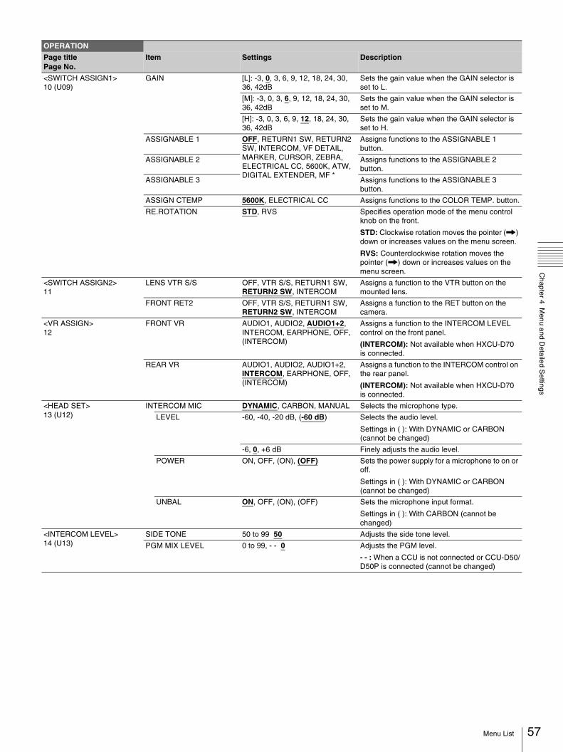
Chapter 4 M
enu and Detailed S
ettings
<SWITCH ASSIGN1> 10 (U09)
GAIN [L]: -3, 0, 3, 6, 9, 12, 18, 24, 30, 36, 42dB
Sets the gain value when the GAIN selector is set to L.
[M]: -3, 0, 3, 6, 9, 12, 18, 24, 30, 36, 42dB
Sets the gain value when the GAIN selector is set to M.
[H]: -3, 0, 3, 6, 9, 12, 18, 24, 30, 36, 42dB
Sets the gain value when the GAIN selector is set to H.
ASSIGNABLE 1 OFF, RETURN1 SW, RETURN2 SW, INTERCOM, VF DETAIL, MARKER, CURSOR, ZEBRA, ELECTRICAL CC, 5600K, ATW, DIGITAL EXTENDER, MF *
Assigns functions to the ASSIGNABLE 1 button.
ASSIGNABLE 2 Assigns functions to the ASSIGNABLE 2 button.
ASSIGNABLE 3 Assigns functions to the ASSIGNABLE 3 button.
ASSIGN CTEMP 5600K, ELECTRICAL CC Assigns functions to the COLOR TEMP. button.
RE.ROTATION STD, RVS Specifies operation mode of the menu control knob on the front.
STD: Clockwise rotation moves the pointer (,) down or increases values on the menu screen.
RVS: Counterclockwise rotation moves the pointer (,) down or increases values on the menu screen.
<SWITCH ASSIGN2> 11
LENS VTR S/S OFF, VTR S/S, RETURN1 SW, RETURN2 SW, INTERCOM
Assigns a function to the VTR button on the mounted lens.
FRONT RET2 OFF, VTR S/S, RETURN1 SW, RETURN2 SW, INTERCOM
Assigns a function to the RET button on the camera.
<VR ASSIGN>12
FRONT VR AUDIO1, AUDIO2, AUDIO1+2, INTERCOM, EARPHONE, OFF, (INTERCOM)
Assigns a function to the INTERCOM LEVEL control on the front panel.
(INTERCOM): Not available when HXCU-D70 is connected.
REAR VR AUDIO1, AUDIO2, AUDIO1+2, INTERCOM, EARPHONE, OFF, (INTERCOM)
Assigns a function to the INTERCOM control on the rear panel.
(INTERCOM): Not available when HXCU-D70 is connected.
<HEAD SET> 13 (U12)
INTERCOM MIC DYNAMIC, CARBON, MANUAL Selects the microphone type.
LEVEL -60, -40, -20 dB, (-60 dB) Selects the audio level.
Settings in ( ): With DYNAMIC or CARBON (cannot be changed)
-6, 0, +6 dB Finely adjusts the audio level.
POWER ON, OFF, (ON), (OFF) Sets the power supply for a microphone to on or off.
Settings in ( ): With DYNAMIC or CARBON (cannot be changed)
UNBAL ON, OFF, (ON), (OFF) Sets the microphone input format.
Settings in ( ): With CARBON (cannot be changed)
<INTERCOM LEVEL> 14 (U13)
SIDE TONE 50 to 99 50 Adjusts the side tone level.
PGM MIX LEVEL 0 to 99, - - 0 Adjusts the PGM level.
- - : When a CCU is not connected or CCU-D50/D50P is connected (cannot be changed)
OPERATION
Page titlePage No.
Item Settings Description
57Menu List
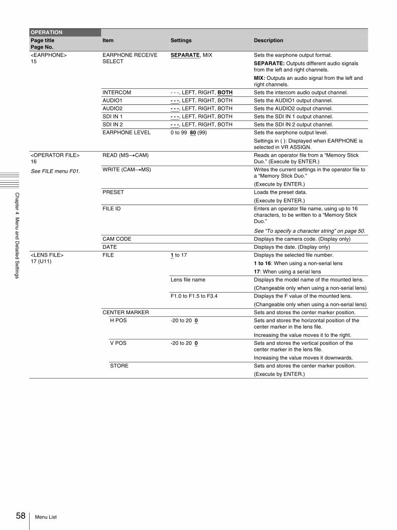
58
Chapter 4 M
enu and Detailed S
ettings
<EARPHONE> 15
EARPHONE RECEIVE SELECT
SEPARATE, MIX Sets the earphone output format.
SEPARATE: Outputs different audio signals from the left and right channels.
MIX: Outputs an audio signal from the left and right channels.
INTERCOM - - -, LEFT, RIGHT, BOTH Sets the intercom audio output channel.
AUDIO1 - - -, LEFT, RIGHT, BOTH Sets the AUDIO1 output channel.
AUDIO2 - - -, LEFT, RIGHT, BOTH Sets the AUDIO2 output channel.
SDI IN 1 - - -, LEFT, RIGHT, BOTH Sets the SDI IN 1 output channel.
SDI IN 2 - - -, LEFT, RIGHT, BOTH Sets the SDI IN 2 output channel.
EARPHONE LEVEL 0 to 99 80 (99) Sets the earphone output level.
Settings in ( ): Displayed when EARPHONE is selected in VR ASSIGN.
<OPERATOR FILE> 16
See FILE menu F01.
READ (MStCAM) Reads an operator file from a “Memory Stick Duo.” (Execute by ENTER.)
WRITE (CAMtMS) Writes the current settings in the operator file to a “Memory Stick Duo.”
(Execute by ENTER.)
PRESET Loads the preset data.
(Execute by ENTER.)
FILE ID Enters an operator file name, using up to 16 characters, to be written to a “Memory Stick Duo.”
See “To specify a character string” on page 50.
CAM CODE Displays the camera code. (Display only)
DATE Displays the date. (Display only)
<LENS FILE> 17 (U11)
FILE 1 to 17 Displays the selected file number.
1 to 16: When using a non-serial lens
17: When using a serial lens
Lens file name Displays the model name of the mounted lens.
(Changeable only when using a non-serial lens)
F1.0 to F1.5 to F3.4 Displays the F value of the mounted lens.
(Changeable only when using a non-serial lens)
CENTER MARKER Sets and stores the center marker position.
H POS -20 to 20 0 Sets and stores the horizontal position of the center marker in the lens file.
Increasing the value moves it to the right.
V POS -20 to 20 0 Sets and stores the vertical position of the center marker in the lens file.
Increasing the value moves it downwards.
STORE Sets and stores the center marker position.
(Execute by ENTER.)
OPERATION
Page titlePage No.
Item Settings Description
Menu List

Chapter 4 M
enu and Detailed S
ettings
PAINT Menu
PAINT
Page titlePage No.
Item Settings Description
<SW STATUS> P01
FLARE ON, OFF Sets the flare compensation function to on or off.
GAMMA ON, OFF Sets the gamma compensation function to on or off.
BLK GAM ON, OFF Sets the black gamma compensation function to on or off.
KNEE ON, OFF Sets the knee compensation function to on or off.
WHT CLIP ON, OFF Sets the white clip compensation function to on or off.
DETAIL ON, OFF Sets the detail compensation function to on or off.
LVL DEP ON, OFF Sets the level depend function to on or off.
SKIN DTL ON, OFF Sets the skin detail compensation function to on or off.
MATRIX ON, OFF Sets the linear matrix and user matrix compensation function to on or off.
<VIDEO LEVEL>
P02
WHITE R/G/B: -99 to 99 0 Sets the gain value for white balance.
BLACK R/G/B/M: -99 to 99 0 Sets the black level value.
FLARE R/G/B/M: -99 to 99 0 Sets the flare compensation level.
GAMMA R/G/B/M: -99 to 99 0 Sets the gamma level.
V MOD R/G/B/M: -99 to 99 0 Sets the V modulation level.
FLARE ON, OFF Sets the flare compensation function to on or off.
V MOD ON, OFF Sets the V modulation shading compensation function to on or off.
D. SHAD ON, OFF Sets the dynamic shading function to on or off.
(Selectable only when a lens supporting dynamic shading is used.)
TEST OFF, SAW, 3STEP, 10STEP Selects the output format of the test signal.
<COLOR TEMP> P03
WHITE R/G/B: -99 to 99 0 Adjusts the white balance gain.
AUTO WHITE BALANCE
Performs the auto white balance adjustment.
(Execute by ENTER.)
COLOR TEMP 0K to 65535K 3200K Sets the color temperature.
BALANCE R/G/B/M: -99 to 99 0 Sets the white balance.
ATW ON, OFF Sets the ATW (Auto Tracing White Balance) function to on or off.
SPEED 1 to 5 4 Selects the tracing speed of the ATW. (1: high, 5: low)
MASTER -3.0dB to 12.0dB, 0.0dB Adjusts the master white gain.
59Menu List

60
Chapter 4 M
enu and Detailed S
ettings
<GAMMA> P04
LEVEL R/G/B/M: -99 to 99 0 Sets the gamma level.
COARSE 0.35 to 0.45 to 0.90
(0.05 steps)
Sets the gamma compensation value in steps of 0.05.
TABLE STANDARD, HYPER Selects either the standard gamma or hypergamma.
With STANDARD selected: 1, 2, 3, 4, 5, 6, 7
1: equivalent to a camera 2: 4.5-times gain 3: 3.5-times gain 4: equivalent to SMPTE-240M 5: equivalent to ITU-R709 6: 5.0-times gain 7: 5.0-times gain - 709
With HYPER selected: 1, 2, 3, 4
1: 325% to 100% 2: 460% to 100% 3: 325% to 109% 4: 460% to 109%
(When you change the TABLE setting, noise may be generated. This is not malfunction.)
Selects the gamma table used for gamma compensation.
GAMMA ON, OFF Sets the gamma compensation function to on or off.
TEST OFF, SAW, 3STEP, 10STEP Selects the test signal displayed on the monitor screen.
<BLACK GAMMA> P05
LEVEL R/G/B/M: -99 to 99 0 Sets the black gamma level (master level only).
RANGE LOW, L.MID, H.MID, HIGH Selects the active range of black gamma compensation.
ON, OFF Sets the black gamma compensation function to on or off.
TEST OFF, SAW, 3STEP, 10STEP Selects the test signal displayed on the monitor screen.
<SATURATION> P06
SATURATION -99 to 99 0 Sets the saturation level.
ON, OFF Sets the saturation function to on or off.
LOW KEY SAT -99 to 99 0 Sets the low key saturation level.
RANGE LOW, L.MID, H.MID, HIGH Selects the saturation range in which the low key saturation function is activated.
ON, OFF Sets the low key saturation function to on or off.
TEST OFF, SAW, 3STEP, 10STEP Selects the test signal displayed on the monitor screen.
<KNEE> P07
K POINT R/G/B/M: -99 to 99 0 Sets the knee point.
K SLOPE R/G/B/M: -99 to 99 0 Sets the knee slope.
KNEE ON, OFF Sets the knee compensation function to on or off.
KNEE MAX ON, OFF Sets the knee max to on or off.
KNEE SAT -99 to 99 0 Sets the knee saturation level.
ON, OFF Sets the knee saturation function to on or off.
AUTO KNEE OFF, AUTO Sets the auto knee function to on or off.
POINT LIMIT -99 to 99 0 Sets the auto knee limiter.
SLOPE -99 to 99 0 Sets the auto knee slope.
ABS Displays the inverted values as absolute values.
<WHITE CLIP> P08
W CLIP -99 to 99 0 Sets the white clip level.
ON, OFF Sets the white clip adjustment function to on or off.
ABS Displays the inverted values as absolute values.
PAINT
Page titlePage No.
Item Settings Description
Menu List
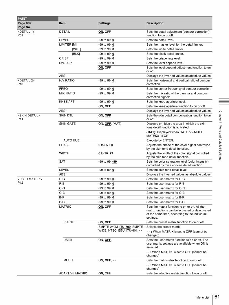
Chapter 4 M
enu and Detailed S
ettings
<DETAIL 1> P09
DETAIL ON, OFF Sets the detail adjustment (contour correction) function to on or off.
LEVEL -99 to 99 0 Sets the detail level.
LIMITER [M] -99 to 99 0 Sets the master level for the detail limiter.
[WHT] -99 to 99 0 Sets the white detail limiter.
[BLK] -99 to 99 0 Sets the black detail limiter.
CRISP -99 to 99 0 Sets the crispening level.
LVL DEP -99 to 99 0 Sets the level depend level.
ON, OFF Sets the level depend adjustment function to on or off.
ABS Displays the inverted values as absolute values.
<DETAIL 2> P10
H/V RATIO -99 to 99 0 Sets the horizontal and vertical ratio of contour correction.
FREQ -99 to 99 0 Sets the center frequency of contour correction.
MIX RATIO -99 to 99 0 Sets the mix ratio of the gamma and contour correction signals.
KNEE APT -99 to 99 0 Sets the knee aperture level.
ON, OFF Sets the knee aperture function to on or off.
ABS Displays the inverted values as absolute values.
<SKIN DETAIL> P11
SKIN DTL ON, OFF Sets the skin detail compensation function to on or off.
SKIN GATE ON, OFF, (MAT) Displays or hides the area in which the skin-tone detail function is activated.
(MAT): Displayed when GATE of <MULTI MATRIX> is ON.
AUTO HUE Execute by ENTER.
PHASE 0 to 359 0 Adjusts the phase of the color signal controlled by the skin-tone detail function.
WIDTH 0 to 90 29 Adjusts the width of the color signal controlled by the skin-tone detail function.
SAT -99 to 99 -89 Sets the color saturation level (color intensity) controlled by the skin-tone detail function.
LEVEL -99 to 99 0 Sets the skin-tone detail level.
ABS Displays the inverted values as absolute values.
<USER MATRIX> P12
R-G -99 to 99 0 Sets the user matrix for R-G.
R-B -99 to 99 0 Sets the user matrix for R-B.
G-R -99 to 99 0 Sets the user matrix for G-R.
G-B -99 to 99 0 Sets the user matrix for G-B.
B-R -99 to 99 0 Sets the user matrix for B-R.
B-G -99 to 99 0 Sets the user matrix for B-G.
MATRIX ON, OFF Sets the matrix function to on or off. All the matrix functions can be activated or deactivated at the same time, according to the individual settings.
PRESET ON, OFF Sets the preset matrix function to on or off.
SMPTE-240M, ITU-709, SMPTE-WIDE, NTSC, EBU, ITU-601, - -
Selects the preset matrix.
- - : When MATRIX is set to OFF (cannot be changed)
USER ON, OFF, - - Sets the user matrix function to on or off. The user matrix settings are available when ON is selected.
- - : When MATRIX is set to OFF (cannot be changed)
MULTI ON, OFF, - - Sets the multi matrix function to on or off.
- - : When MATRIX is set to OFF (cannot be changed)
ADAPTIVE MATRIX ON, OFF Sets the adaptive matrix function to on or off.
PAINT
Page titlePage No.
Item Settings Description
61Menu List
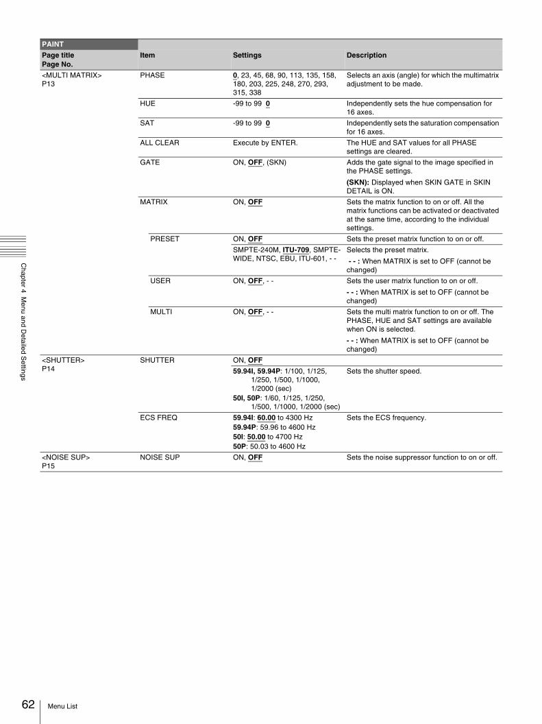
62
Chapter 4 M
enu and Detailed S
ettings
<MULTI MATRIX> P13
PHASE 0, 23, 45, 68, 90, 113, 135, 158, 180, 203, 225, 248, 270, 293, 315, 338
Selects an axis (angle) for which the multimatrix adjustment to be made.
HUE -99 to 99 0 Independently sets the hue compensation for 16 axes.
SAT -99 to 99 0 Independently sets the saturation compensation for 16 axes.
ALL CLEAR Execute by ENTER. The HUE and SAT values for all PHASE settings are cleared.
GATE ON, OFF, (SKN) Adds the gate signal to the image specified in the PHASE settings.
(SKN): Displayed when SKIN GATE in SKIN DETAIL is ON.
MATRIX ON, OFF Sets the matrix function to on or off. All the matrix functions can be activated or deactivated at the same time, according to the individual settings.
PRESET ON, OFF Sets the preset matrix function to on or off.
SMPTE-240M, ITU-709, SMPTE-WIDE, NTSC, EBU, ITU-601, - -
Selects the preset matrix.
- - : When MATRIX is set to OFF (cannot be changed)
USER ON, OFF, - - Sets the user matrix function to on or off.
- - : When MATRIX is set to OFF (cannot be changed)
MULTI ON, OFF, - - Sets the multi matrix function to on or off. The PHASE, HUE and SAT settings are available when ON is selected.
- - : When MATRIX is set to OFF (cannot be changed)
<SHUTTER> P14
SHUTTER ON, OFF
59.94I, 59.94P: 1/100, 1/125, 1/250, 1/500, 1/1000, 1/2000 (sec)
50I, 50P: 1/60, 1/125, 1/250, 1/500, 1/1000, 1/2000 (sec)
Sets the shutter speed.
ECS FREQ 59.94I: 60.00 to 4300 Hz 59.94P: 59.96 to 4600 Hz50I: 50.00 to 4700 Hz 50P: 50.03 to 4600 Hz
Sets the ECS frequency.
<NOISE SUP> P15
NOISE SUP ON, OFF Sets the noise suppressor function to on or off.
PAINT
Page titlePage No.
Item Settings Description
Menu List
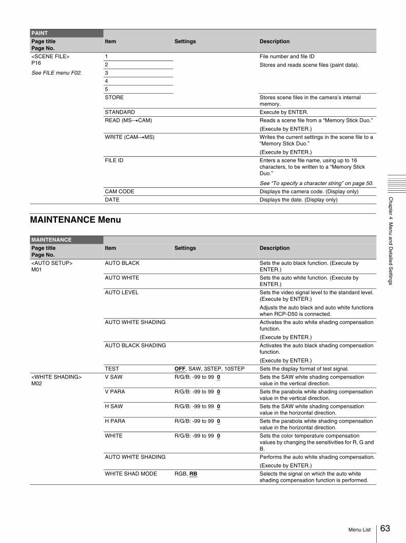
Chapter 4 M
enu and Detailed S
ettings
MAINTENANCE Menu
<SCENE FILE> P16
See FILE menu F02.
1 File number and file ID
Stores and reads scene files (paint data).2
3
4
5
STORE Stores scene files in the camera’s internal memory.
STANDARD Execute by ENTER.
READ (MStCAM) Reads a scene file from a “Memory Stick Duo.”
(Execute by ENTER.)
WRITE (CAMtMS) Writes the current settings in the scene file to a “Memory Stick Duo.”
(Execute by ENTER.)
FILE ID Enters a scene file name, using up to 16 characters, to be written to a “Memory Stick Duo.”
See “To specify a character string” on page 50.
CAM CODE Displays the camera code. (Display only)
DATE Displays the date. (Display only)
MAINTENANCE
Page titlePage No.
Item Settings Description
<AUTO SETUP> M01
AUTO BLACK Sets the auto black function. (Execute by ENTER.)
AUTO WHITE Sets the auto white function. (Execute by ENTER.)
AUTO LEVEL Sets the video signal level to the standard level. (Execute by ENTER.)
Adjusts the auto black and auto white functions when RCP-D50 is connected.
AUTO WHITE SHADING Activates the auto white shading compensation function.
(Execute by ENTER.)
AUTO BLACK SHADING Activates the auto black shading compensation function.
(Execute by ENTER.)
TEST OFF, SAW, 3STEP, 10STEP Sets the display format of test signal.
<WHITE SHADING> M02
V SAW R/G/B: -99 to 99 0 Sets the SAW white shading compensation value in the vertical direction.
V PARA R/G/B: -99 to 99 0 Sets the parabola white shading compensation value in the vertical direction.
H SAW R/G/B: -99 to 99 0 Sets the SAW white shading compensation value in the horizontal direction.
H PARA R/G/B: -99 to 99 0 Sets the parabola white shading compensation value in the horizontal direction.
WHITE R/G/B: -99 to 99 0 Sets the color temperature compensation values by changing the sensitivities for R, G and B.
AUTO WHITE SHADING Performs the auto white shading compensation.
(Execute by ENTER.)
WHITE SHAD MODE RGB, RB Selects the signal on which the auto white shading compensation function is performed.
PAINT
Page titlePage No.
Item Settings Description
63Menu List

64
Chapter 4 M
enu and Detailed S
ettings
<BLACK SHADING> M03
V SAW R/G/B: -99 to 99 0 Sets the SAW black shading compensation value in the vertical direction.
V PARA R/G/B: -99 to 99 0 Sets the parabola black shading compensation value in the vertical direction.
H SAW R/G/B: -99 to 99 0 Sets the SAW black shading compensation value in the horizontal direction.
H PARA R/G/B: -99 to 99 0 Sets the parabola black shading compensation value in the horizontal direction.
BLK SET R/G/B: -99 to 99 0 Individually sets the compensation values for R, G and B.
BLACK R/G/B/M: -99 to 99 0 Individually sets the black levels for R, G and B. Sets the black level by controlling all the settings for R, G and B.
MASTER GAIN -3, 0, 3, 6, 9, 12dB Sets the master gain value.
AUTO BLACK SHADING Performs the auto black shading compensation.
(Execute by ENTER.)
<AUTO IRIS> M04
AUTO IRIS ON, OFF Activates the auto iris function.
WINDOW 1, 2, 3, 4, 5, 6 Selects the auto iris window:
The shaded parts indicate the area where light detection occurs.
OVERRIDE -99 to 99 - - Sets the override to temporarily change the reference value for brightness of the automatic iris level in the range of ±2 steps.
-99: Two steps to fully closed iris
99: Two steps to fully open iris
- - : OFF
The setting returns to “- -” when the power is turned off.
IRIS LEVEL -99 to 99 0 Sets the auto iris level.
APL RATIO -99 to 99 65 Adjusts the auto iris APL ratio (ratio of the peak auto iris level and average auto iris level).
IRIS GAIN -99 to 99 0 Sets the auto iris response speed.
IRIS CLOSE ON, OFF Closes the lens aperture.
MAINTENANCE
Page titlePage No.
Item Settings Description
1 2 3
4 5 6
Menu List

Chapter 4 M
enu and Detailed S
ettings
<CIS COMP>M05
FLICKER REDUCE Settings related to the flicker compensation function.
MODE AUTO, ON, OFF Enables or disables flicker reduction.
AUTO: Enabled when flicker is detected.
ON: Always enabled.
OFF: Disabled
FREQ 60 Hz, 50 Hz Set to the frequency of the lighting fixture that is causing the flicker. (The factory default setting is 50 Hz when the area setting is PAL area, 60 Hz when it is other than PAL area.)
FLASH BAND COMP Settings related to the flash band compensation.
COMP ON, OFF, (OFF) Sets the flash band compensation function to on or off.
(OFF): Displayed when the shutter function is activated.
– ON can be selected only when the shutter function is deactivated.
– The COMP setting is automatically switched from ON to (OFF) when the shutter function becomes activated. The setting returns to ON when the shutter function becomes deactivated.
<AUDIO> M06 (U14)
MIC GAIN
AUDIO1 20dB, 30dB, 40dB, 50dB, 60dB Sets the input gain of the AUDIO 1 IN connector for an external microphone.
Settings in ( ): When HXCU-D70 is connected (cannot be changed)
AUDIO2 20dB, 30dB, 40dB, 50dB, 60dB Sets the input gain of the AUDIO 2 IN connector for an external microphone.
Settings in ( ): When HXCU-D70 is connected (cannot be changed)
CCZ OUT Adjusts the microphone output settings when the CCU-D50/D50P is connected.
AUDIO 1 ON, OFF Outputs the audio signal input from the AUDIO 1 IN connector to the CCU.
Settings in ( ): When HXCU-D70 is connected (cannot be changed)
AUDIO 2 ON, OFF Outputs the audio signal input from the AUDIO 2 IN connector to the CCU.
Settings in ( ): When HXCU-D70 is connected (cannot be changed)
TEST TONE ON, OFF Sets the test tone function to on or off.
Returns to OFF every time the power is turned on.
<CALL/TALLY>M07
CCU CALL - - -, ON, OFF Displays the CALL signal from the CCU.
- - -: When a CCU is not connected
CAM CALL - - -, ON, OFF Displays the CALL signal from the camera.
- - -: When a CCU is not connected
MAINTENANCE
Page titlePage No.
Item Settings Description
65Menu List

66
Chapter 4 M
enu and Detailed S
ettings
<OUTPUT FORMAT> M08 (U15)
CURRENT Displays the current format.
ACTIVE LINE
Not displayed when a CCU is connected. Displayed when CCU-D50/D50P is connected.
[1080] 59.94i, 50i[720] 59.94P, 50P(When you change the ACTIVE LINE setting, once turn the camera off. The camera will operate in the selected mode when next turned on.)
Set this item when turning the unit on for the first time. Selectable formats vary depending on the area of use.
COUNTRY NTSC AREA, NTSC(J) AREA, PAL AREA
Sets the area of use.
For details, see “Setting the Area of Use” (page 27).
A restart is required after setting.
<DOWN CONVERTER> M09 (U17)
OUTPUT SIGNAL (MAIN) (Display only)
SETTING CAM, CCU When a CCU is connected: Either CAM (settings made with the camera) or CCU (settings taken from the linked CCU) can be selected. When a CCU is connected, the values for the following items displayed in parenthesis cannot be changed with the camera.
When a CCU is not connected:This item is not displayed.
ASPECT SQ, EC Sets the aspect mode for down-converting.
SQ: Squeeze (16:9)
EC: Edge crop (4:3)
BARS MODE DISABLE, SMPTE, FULL (75%), FULL (100%)
Selects the color bar for SD signal.
Outputs a down-converted HD BARS signal when DISABLE is selected.
SD CCS ON, OFF Sets the cross color suppression function to on or off.
-99 to 99 0 Sets the cross color suppression level.
SD DETAIL ON, OFF Sets the detail adjustment function for down-converted output to on or off.
-99 to 99 0 Sets the SD detail signal level.
CRISP -99 to 99 0 Sets the crispening level.
LVL DEP -99 to 99 0 Sets the level depend level.
H/V RATIO -99 to 99 0 Sets the horizontal and vertical ratio for the detail signal to be added.
H DTL FREQ -99 to 99 0 Sets the detection center frequency of the H detail signal.
<TEST OUT> M10 (U16)
OUTPUT SD-SYNC, VF, HD-SYNC, VBS Sets the signal to be output from the TEST OUT connector.
VBS-OUT Available when VBS is selected in TEST OUT > OUTPUT in the setup menu.
CHARACTER ON, OFF Adds the character signals.
SYNC-OUT Available when SD-SYNC or HD-SYNC is selected in TEST OUT > OUTPUT in the setup menu.
V-PHASE -1024 to 1023 0 Adjusts the vertical phase for SYNC-OUT.
H-PHASE -1700 to 1700 0 Adjusts the horizontal phase for SYNC-OUT.
<SDI OUT> M11
OUTPUT MAIN, VF, RET, SD-SDI Selects the output signal from the SDI OUT connector. Available when ACTIVE is selected in MAINTENANCE > POWER SAVE > SDI OUT in the setup menu.
CHARACTER ON, OFF Displayed when OUTPUT is set to SD-SDI.
MAINTENANCE
Page titlePage No.
Item Settings Description
Menu List

Chapter 4 M
enu and Detailed S
ettings
<CCZ OUT>M12
OUTPUT YCrCb, YC, RGB, - - - Sets the signal to be output from the CCZ-A connector when the camera is used on its own.
Settings in ( ): When CCU-D50/D50P is connected
- - -: When a CCU other than CCU-D50/D50P is connected
<POWER SAVE>M13 (U10)
SDI OUT PWR SAVE, ACTIVE Sets the power save mode for the SDI OUT connector.
DOWN CONVERTER PWR SAVE, ACTIVE, (ACTIVE) Sets the power save mode for the down-converted output.
(ACTIVE): When CCU-D50/D50P is connected (cannot be changed)
D.EXTENDER ENABLE, DISABLE Sets the power save mode while the digital extender function is not used.
ENABLE: When the digital extender function is used.
DISABLE: When the digital extender function is not used.
<GENLOCK> M14
Items other than REFERENCE are not displayed when a CCU is connected. They are displayed when CCU-D50/D50P is connected.
REFERENCE CCU, INTERNAL, GENLOCK Condition of synchronisation (Display only)
GENLOCK DISABLE, ENABLE Activates or deactivates the genlock function.
STATUS Indicates the signal format input to the GENLOCK connecter. (Display only)FORMAT
V PHASE -1024 to 1023 0 Adjusts the vertical phase for GENLOCK.
H PHASE -1700 to 1700 0 Adjusts the horizontal phase for GENLOCK.
H FINE -99 to 99 0 Finely adjusts the horizontal phase for GENLOCK (Available only for SD output).
SC PHASE 0 to 359 0 Adjusts the subcarrier phase (Available only for VBS output).
<DATE> M15
DATE/TIME yyyy/mm/dd hh:mm
Display format varies depending on the DAY TYPE settings on the <OTHERS 2> page.
<BATTERY ALARM> M16
BEFORE END 11.5 V to 17.0 V Sets the threshold for displaying the message “Battery Near End.”
END 11.0 V to 11.5 V Sets the threshold for displaying the message “Battery End.”
<WHITE FILTER> M17
ELECTRICAL CC <A> 3200K, 4300K, 5600K, 6300K Switches between the built-in electrical CC filters.
The 5600K mode indication lights up when 5600K is selected.
ELECTRICAL CC <B> 3200K, 4300K, 5600K, 6300K
ELECTRICAL CC <C> 3200K, 4300K, 5600K, 6300K, - - - -
ELECTRICAL CC <D> 3200K, 4300K, 5600K, 6300K, - - - -
MAINTENANCE
Page titlePage No.
Item Settings Description
67Menu List

68
Chapter 4 M
enu and Detailed S
ettings
<OTHERS 1> M18
CAM BARS ON, OFF Displays or hides the color bar signal.
V DTL CREATION NAM, G, R+G, Y Selects the source signal of V DTL.
DTL H/V MODE H/V, V Only Selects the operating mode of the H/V RATIO function in DETAIL 2.
H/V: H and V increase and decrease in inverse proportion.
V Only: V DTL only enabled.
TEST2 MODE 3STEP, 10STEP Selects the TEST2 signal.
WHITE SETUP MODE AWB, A.LVL Selects the white balance setting when the auto setup function is performed or all the settings are cleared.
AWB: Returns to the previous setting.
A.LVL: Returns to the setting stored in the reference file.
ALAC AUTO, OFF Activates the ALAC (Auto Lens Aberration Compensation) function.
With AUTO selected, the status is displayed at the right.
(ACTIVE): Compensation in progress
(WAIT): Waiting for completion of lens initialization
(STOP): Compensation is turned off for a non-applicable lens
AUTO FLANGE BACK Activates the auto flange back function.
(Execute by ENTER.)
HDSDI REMOTE I/F OFF, R-TLY Selects whether to activate the recording-control function for an external device connected to the SDI OUT connector. Available when MAIN is selected in MAINTENANCE > SDI OUT > OUTPUT in the setup menu.
<OTHERS 2> M19
DATE TYPE 1 Y/Mn/D, 2 Mn/D, 3 D/M/Y, 4 D/M, 5 M/D/Y, 6 M/D
Selects the date display format.
Y: Year
Mn: Month (numeric)
M: Month (character string)
D: Day
F NO. DISP CONTROL, RETURN Selects the iris indication on the panel when AUTO IRIS is off.
CONTROL: To display the value from the camera
RETURN: To display the value returned from the lens (When AUTO IRIS is on, the value returned from the lens is always displayed.)
AF DETECT AREA CENTER, VARIABLE Sets the auto-focus detection area.
CENTER: Fixed auto-focus detection area at the center
VARIABLE: Adjustable auto-focus detection area
<EXT RETURN> M20
EXT RETURN VBS, SDI Selects the input signal format displayed in the viewfinder when the RET button is pressed. SDI is not available when a CCU is connected.
SD ASPECT EC, SQ EC: Select this when the aspect ratio of the VBS input signal is 4:3.
SQ: Select this when the aspect ratio of the VBS input signal is 16:9.
MAINTENANCE
Page titlePage No.
Item Settings Description
Menu List

Chapter 4 M
enu and Detailed S
ettings
FILE Menu
Five types of files can be used for easy adjustments of the camera; Operator, Reference, Scene, OHB, and Lens.You can store the items set with the OPERATION menu and customized USER menu in the Operator file.
For the specific items included in these files, refer to the Maintenance Manual.
FILE
Page titlePage No.
Item Settings Description
<OPERATOR FILE> F01
READ (MStCAM) Reads an operator file from a “Memory Stick Duo.” (Execute by ENTER.)
WRITE (CAMtMS) Writes the current settings in the operator file to a “Memory Stick Duo.”
(Execute by ENTER.)
PRESET Loads the preset data.
(Execute by ENTER.)
STORE PRESET FILE Stores the settings (preset data) on the OPERATION menu in the camera’s internal memory.
(Execute by ENTER.)
FILE ID Enters an operator file name, using up to 16 characters, to be written to a “Memory Stick Duo.”
See “To specify a character string” on page 50.
CAM CODE Displays the camera code. (Display only)
DATE Displays the date. (Display only)
<SCENE FILE> F02
1 File number and file ID
Stores and reads scene files (paint data).2
3
4
5
STORE Stores scene files in the camera's internal memory.
STANDARD Execute by ENTER.
READ (MStCAM) Reads scene files from a “Memory Stick Duo.”
(Execute by ENTER.)
WRITE (CAMtMS) Writes the current settings in the scene file to a “Memory Stick Duo.”
(Execute by ENTER.)
FILE ID Enters a scene file name, using up to 16 characters, to be written to a “Memory Stick Duo.”
See “To specify a character string” on page 50.
CAM CODE Displays the camera code. (Display only)
DATE Displays the date. (Display only)
69Menu List
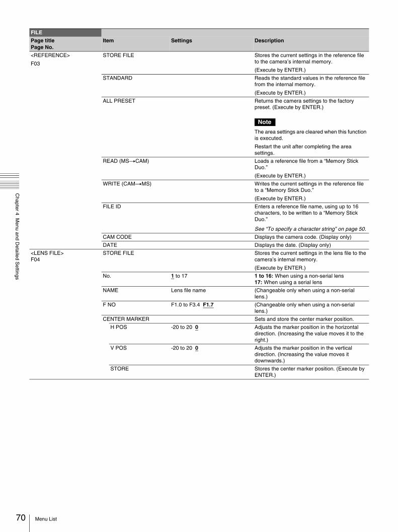
70
Chapter 4 M
enu and Detailed S
ettings
<REFERENCE>
F03
STORE FILE Stores the current settings in the reference file to the camera’s internal memory.
(Execute by ENTER.)
STANDARD Reads the standard values in the reference file from the internal memory.
(Execute by ENTER.)
ALL PRESET Returns the camera settings to the factory preset. (Execute by ENTER.)
Note
The area settings are cleared when this function is executed.
Restart the unit after completing the area settings.
READ (MStCAM) Loads a reference file from a “Memory Stick Duo.”
(Execute by ENTER.)
WRITE (CAMtMS) Writes the current settings in the reference file to a “Memory Stick Duo.”
(Execute by ENTER.)
FILE ID Enters a reference file name, using up to 16 characters, to be written to a “Memory Stick Duo.”
See “To specify a character string” on page 50.
CAM CODE Displays the camera code. (Display only)
DATE Displays the date. (Display only)
<LENS FILE> F04
STORE FILE Stores the current settings in the lens file to the camera’s internal memory.
(Execute by ENTER.)
No. 1 to 17 1 to 16: When using a non-serial lens 17: When using a serial lens
NAME Lens file name (Changeable only when using a non-serial lens.)
F NO F1.0 to F3.4 F1.7 (Changeable only when using a non-serial lens.)
CENTER MARKER Sets and store the center marker position.
H POS -20 to 20 0 Adjusts the marker position in the horizontal direction. (Increasing the value moves it to the right.)
V POS -20 to 20 0 Adjusts the marker position in the vertical direction. (Increasing the value moves it downwards.)
STORE Stores the center marker position. (Execute by ENTER.)
FILE
Page titlePage No.
Item Settings Description
Menu List

Chapter 4 M
enu and Detailed S
ettings
DIAGNOSIS Menu
This menu is only for viewing and no setting is made using this menu.
<FILE CLEAR> F05
PRESET OPERATOR Returns the operator file to the factory preset. (Execute by ENTER.)
REFERENCE (ALL) Returns the reference file to the factory preset. (Execute by ENTER.)
10 SEC CLEAR ON, OFF Clears a specific item in the reference file by holding the menu control knob pressed for 10 seconds.
See “To return a menu item to its standard value” (page 50).
ALL MENU RESET Returns all the settings to the factory preset.
M.S. FORMAT Initializes a “Memory Stick Duo.” (Execute by ENTER.)
Note
Clears all the data stored in a “Memory Stick Duo.”
DIAGNOSIS
Page titlePage No.
Item Settings Description
<BOARD STATUS>
D01
OHB OK, NG Displays the OHB Block status.
DPR OK, NG Displays the DPR board status.
SY OK, NG Displays the SY board status.
IF OK, NG Displays the IF board status.
PS OK, NG Displays the PS board status.
<PLD VERSION>
D02
SY Displays the PLD version for SY board.
DPR1 Displays the PLD1 version for DPR board.
DPR2 Displays the PLD2 version for DPR board.
IF Displays the PLD version for IF board.
TX Displays the TX-PLD version for DPR board.
<ROM VERSION>
D03 (U18)
AT Display the ROM (software) version.
<SERIAL NO>
D04
MODEL MODEL NAME Displays the model name.
NO SERIAL NO Displays the serial number.
FILE
Page titlePage No.
Item Settings Description
71Menu List
hapter5
72
Chapter 5 M
aintenance
CMaintenance
Testing the camera
Check the functions of the camera before setting out for a shooting session, preferably by recording and playing back video and audio signals.
Maintenance
Cleaning the Viewfinder
Use a dust blower to clean the lens, the LCD screen, and mirror inside the viewfinder barrel.
Note
Never use organic solvents such as thinners.
Note about the Battery Terminal
The battery terminal of this unit (the connector for battery packs and AC adaptors) is a consumable part.Power may not be supplied to the unit properly if the pins of the battery terminal are bent or deformed by shock or vibrations, or if they become corroded due to prolonged outdoor use.Periodic inspections are recommended to keep the unit working properly and to prolong its usable lifetime.Contact your Sony dealer or a Sony service representative for more information about inspections.
Testing the camera / Maintenance

Chapter 5 M
aintenance
Error Messages
If a problem occurs during operation, a warning message is displayed.
Note
To display a message, set the DISPLAY/MENU switch to DISPLAY or MENU.
Message Meaning
TEMP WARNING The internal temperature is extraordinarily high.
FAN STOP The built-in fan is not rotating properly.
SET SYSTEM CLOCK The time/date of the internal clock have not been set.
OHB BLOCK NG! A problem is detected in the optical block.
MSU RPN BUSY RPN compensation was attempted using the camera menu while being operated from an external device.
Consult Sony service personnel.
VF RPN BUSY RPN compensation was attempted from an external device while being operated using the camera menu.
Consult Sony service personnel.
NO MEMORY STICK A “Memory Stick Duo” operation was attempted with no “Memory Stick Duo” in the slot.
MEMORY STICK ERROR
An error occurred during access to a “Memory Stick Duo.”
FORMAT ERROR! A “Memory Stick Duo” operation was attempted with an unformatted “Memory Stick Duo.”
MEMORY STICK LOCKED
File writing was attempted with a write-protected “Memory Stick Duo.”
FILE ERROR An error occurred while reading a file from a “Memory Stick Duo.”
OTHER MODEL’S FILE You attempted to read a file of other models having no compatibility.
FILE NOT FOUND The file you attempted to read does not exist in the “Memory Stick Duo.”
73Error Messages

74
Appendix
Appendix
Important Notes on Operation
Use and storage
Do not subject the camera to severe shocks• The internal mechanism may be damaged or the body
warped.• If an accessory mounted on the accessory shoe is subjected
to severe shock, the accessory shoe may be damaged. In such a case, stop using it and contact your Sony dealer or a Sony service representative.
Do not cover the camera while operatingPutting a cloth, for example, over the camera can cause excessive internal heat build-up.
After useAlways turn off the power switch.
Before storing the camera for a long periodRemove the battery pack.
ShippingIf sending the camera by truck, ship, air or other transportation service, pack it in the shipping carton of the camera.
Care of the cameraRemove dust and dirt from the surfaces of the lenses or optical filters using a blower.If the body of the camera is dirty, clean it with a soft, dry cloth. In extreme cases, use a cloth steeped in a little neutral detergent, then wipe dry. Do not use organic solvents such as alcohol or thinners, as these may cause discoloration or other damage to the finish of the camera.
In the event of operating problemsIf you should experience problems with the camera, contact your Sony dealer or a Sony service representative.
Use and storage locationsStore in a level, ventilated place. Avoid using or storing the camera in the following places.
• In excessive heat or cold (operating temperature range: 0°C to 40°C (32°F to 104°F)). Remember that in summer in warm climates the temperature inside a car with the windows closed can easily exceed 50°C (122°F).
• In damp or dusty locations• Locations where the camera may be exposed to rain• Locations subject to violent vibration• Near strong magnetic fields• Close to radio or TV transmitters producing strong
electromagnetic fields.• In direct sunlight or close to heaters for extended periods
To prevent electromagnetic interference from portable communications devicesThe use of portable telephones and other communications devices near this camera can result in malfunctions and interference with audio and video signals.It is recommended that the portable communications devices near this camera be powered off.
Note on laser beamsLaser beams may damage the CMOS image sensors.If you shoot a scene that includes a laser beam, be careful not to let the laser beam be directed into the lens of the camera.
Fitting the zoom lensIt is important to fit the lens correctly, as otherwise damage may result. Be sure to refer to the section “Mounting and Adjusting the Lens” (page 29).
ViewfinderDo not leave the camera with the eyepiece pointing directly at the sun.The eyepiece lens can concentrate the sun’s rays and melt the interior of the viewfinder.
Important Notes on Operation

Appendix
About the LCD panelsLCD panels are manufactured with extremely high-precision technology that yields effective pixel rates of 99.99% or higher. However, very rarely, one or more pixels may be permanently dark or permanently lit in white, red, blue, or green.This phenomenon is not a malfunction. Such pixels have no effect on the recorded data, and the camera may be used with confidence even if they are present.
Phenomena specific to CMOS image sensorsThe following phenomena that may appear in images are specific to CMOS (Complementary Metal Oxide Semiconductor) image sensors. They do not indicate malfunctions.
White flecksAlthough the CMOS image sensors are produced with high-precision technologies, fine white flecks may be generated on the screen in rare cases, caused by cosmic rays, etc. This is related to the principle of CMOS image sensors and is not a malfunction.The white flecks especially tend to be seen in the following cases:• when operating at a high environmental temperature• when you have raised the master gain (sensitivity)The problem may be alleviated by executing automatic black balance adjustment.
AliasingWhen fine patterns, stripes, or lines are shot, they may appear jagged or flicker.
FlickerIf recording is made under lighting produced by discharge tubes, such as fluorescent, sodium, or mercury-vapor lamps, the screen may flicker, colors may vary, or horizontal stripes may appear distorted.
In such cases, set the flicker-reduction function to auto mode (see page 65).If the frame rate selected for recording is close to the power-supply frequency, flicker may not be reduced sufficiently even if you activate the Flicker-Reduction function. In such cases, use the electronic shutter.
Focal planeOwing to the characteristics of the pickup elements (CMOS image sensors) for reading video signals, subjects that quickly move across the screen may appear slightly skewed.
Flash bandThe luminance at the top and bottom of the screen may change when shooting a flashlight beam or a light source that quickly flashes.
Using a “Memory Stick Duo”
You can use “Memory Stick Duo” media with the camera. When a “Memory Stick Duo” is inserted in the camera, the file data can be stored on the “Memory Stick Duo,” which enables you to share data among devices. The camera operations have been checked using “Memory Stick Duo” media up to 8GB.
Note
Only a “Memory Stick” of Duo size can be used with the camera.
Inserting a “Memory Stick Duo”1 Push the cover down, and 2 insert a “Memory Stick Duo” with the label side facing up into the slot until it clicks and the access lamp lights in red. When the “Memory Stick Duo” is properly set, the lamp lights in green.
Note
Be sure to insert a “Memory Stick Duo” in the right direction. If it does not fit into the slot properly or if there is some resistance when you insert it, the “Memory Stick Duo” may be turned around or upside-down. Do not force the “Memory Stick Duo” into the slot. Confirm the direction of the notch and arrow on the “Memory Stick Duo” before inserting the “Memory Stick Duo,” and then try inserting it again.
Removing a “Memory Stick Duo”Confirm that the access lamp is not lit in red, then lightly push in the “Memory Stick Duo” to release the lock.
Note
If the access lamp is lit in red, data is being read from or written to the “Memory Stick Duo.” At this time, do not shake the product or subject it to shock. Do not turn off the power to the product or remove the “Memory Stick Duo.” Doing so may damage the data.
Label side
“Memory Stick Duo”
75Using a “Memory Stick Duo”

76
Appendix
Protecting saved dataTo prevent accidental erasure of important setup data, use the LOCK switch on the “Memory Stick Duo.” Slide the switch upward to the write protect position. This ensures that you cannot inadvertently overwrote data on the “Memory Stick Duo.”
Note
When using “Memory Stick Duo” media that does not have a LOCK switch, be careful not to inadvertently overwrite or erase your data.
Precautions• Do not attach anything other than the supplied label to the
“Memory Stick Duo” labeling position.• Attach the label so that it does not stick out beyond the
labeling position.• Carry and store the “Memory Stick Duo” in its case.• Do not touch the connector of the “Memory Stick Duo” with
anything, including your finger or metallic objects.• Do not strike, bend, or drop the “Memory Stick Duo.”• Do not disassemble or modify the “Memory Stick Duo.”• Do not allow the “Memory Stick Duo” to get wet.• Do not use or store the “Memory Stick Duo” in a location that
is:– Extremely hot, such as in a car parked in the sun– Under direct sunlight– Very humid or subject to corrosive substances
• To prevent data loss, make backups of data frequently. In no event will Sony be liable for any loss of data.
• Unauthorized recording may be contrary to the provisions of copyright law. When you use a “Memory Stick Duo” that has been pre-recorded, be sure that the material has been recorded in accordance with copyright and other applicable laws.
Exchanging the Battery of the Internal Clock
The camera’s internal clock is powered by a lithium battery. If the message “BackUp Battery End” appears in the viewfinder, this battery must be exchanged. Contact your Sony dealer or a Sony service representative.
• “Memory Stick” and are trademarks of Sony Corporation.
• “Memory Stick Duo” and are trademarks of Sony Corporation.
LOCK switch
Exchanging the Battery of the Internal Clock

Appendix
Specifications
General
Power requirements 12 V DC (10.5 V to 17.0 V)
Power consumption Approx. 1.92 A
Main unit (camera) + LCD viewfinder + auto focus lens + microphone
Operating temperature –10°C to +45°C (14°F to 113°F)
Storage temperature –20°C to +60°C (–4°F to 140°F)
Recording formats 1920 × 1080/59.94i, 50i 1280 × 720/59.94P, 50P
Mass Main body only: 3.4 kg (7 lb 7.9 oz)
Dimensions See page 78.
Supplied accessories See page 77.
Camera Block
Camera Block 2/3-type, CMOS image sensor Effective picture elements:
1920 (H) × 1080 (V)
Format 3-chip RGB
Optical system F1.4 prism system
ND filters 1: Clear
2: 1/4ND
3: 1/16ND
4: 1/64ND
Sensitivity F12 (System frequency: 59.94i) F13 (System frequency: 50i) (2000lx,
89.9% reflection)
Video S/N 56 dB (Noise Suppress Off)
59 dB (Noise Suppress On)
Horizontal resolution 1000TV lines or more
Gain –3, 0, 3, 6, 9, 12 dB
Shutter speed 59.94i/P, 50i/P: 1/60 to 1/2000 sec.
Display (Viewfinder (supplied))
Screen size 8.8 cm diagonal (3.5-inch)
Aspect ratio 16:9
Picture elements 640 (H) × 3 × 480 (V) Sequence delta
Inputs/Outputs
CCU CCZ connector (1)
AUDIO 1 IN/AUDIO 2 IN
XLR type, 3-pin, female (1 each) MIC IN: –60 dBu
(Up to –20 dBu can be set by using menu or HXCU-D70), balanced
LINE IN: 0 dBu, balanced
INTERCOM XLR type, 5-pin, female (1)
EARPHONE Stereo minijack (1)
DC IN XLR type, 4-pin (1), 10.5 to 17.0 V DC
DC OUT 4-pin (1), 10.5 to 17.0 V DC, maximum rated current: 1.5 A
(The numerical value may vary, depending on usage conditions.)
SDI IN BNC type (1)
SDI OUT BNC type (1)
TEST OUT BNC type (1)
PROMPTER/GENLOCK
BNC type (1), 1.0 Vp-p, 75 Ω
LENS 12-pin (1), supplying power to the lens, 10.5 to 17.0 V DC, maximum rated current: 1.0 A
TRUNK D-sub 9-pin, female (1), RS-232C 1 system
VF 26-pin rectangular (1), 20-pin round (1)
REMOTE 8-pin (1)
Lens Block (HXC-D70K only)
Focal length 8 mm (11/32 inches) to 128 mm (5 1/8 inches)
(equivalent to 31.5 mm (1 1/4 inches) to 503 mm (19 7/8 inches) on 35 mm (1 7/16 inches) lens)
Zoom Servo/Manual selectable
Zoom ratio 16×
Maximum relative aperture
1:1.9
Iris Auto/Manual selectable
F1.9 to F16 and C (close)
Focus Auto/Manual selectable Ranges:
800 mm (31 1/2 inches) to ∞ (Macro OFF) 50 mm (2 inches) to ∞ (Macro ON, Wide)
Filter thread M82 mm, pitch 0.75 mm
Macro ON/OFF switchable
Supplied Accessories
Viewfinder (HXC-D70K/D70L only) (1)
Microphone (HXC-D70K/D70L only) (1)
Windscreen (HXC-D70K/D70L only) (1)
Lens mount cap (1)
Flange back adjustment chart (1)
Auto focus lens (HXC-D70K only) (1)
Cable clamp belt (1)
Hexagonal wrench (supplied with HXC-D70H) (1)
Fitting Shoe for DXF-801 viewfinder (supplied with HXC-D70H) (1)
Operating Instructions Japanese version (1)English version (1)
CD-ROM (1)
Warranty (1)
77Specifications
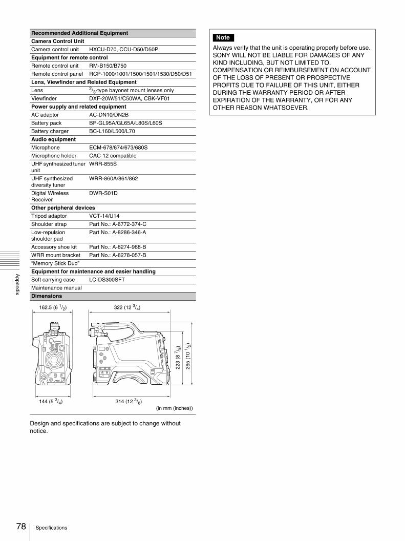
78
Appendix
Design and specifications are subject to change without notice.
Recommended Additional Equipment
Camera Control Unit
Camera control unit HXCU-D70, CCU-D50/D50P
Equipment for remote control
Remote control unit RM-B150/B750
Remote control panel RCP-1000/1001/1500/1501/1530/D50/D51
Lens, Viewfinder and Related Equipment
Lens 2/3-type bayonet mount lenses only
Viewfinder DXF-20W/51/C50WA, CBK-VF01
Power supply and related equipment
AC adaptor AC-DN10/DN2B
Battery pack BP-GL95A/GL65A/L80S/L60S
Battery charger BC-L160/L500/L70
Audio equipment
Microphone ECM-678/674/673/680S
Microphone holder CAC-12 compatible
UHF synthesized tuner unit
WRR-855S
UHF synthesized diversity tuner
WRR-860A/861/862
Digital Wireless Receiver
DWR-S01D
Other peripheral devices
Tripod adaptor VCT-14/U14
Shoulder strap Part No.: A-6772-374-C
Low-repulsion shoulder pad
Part No.: A-8286-346-A
Accessory shoe kit Part No.: A-8274-968-B
WRR mount bracket Part No.: A-8278-057-B
“Memory Stick Duo”
Equipment for maintenance and easier handling
Soft carrying case LC-DS300SFT
Maintenance manual
Dimensions
322 (12 3/4)
314 (12 3/8)144 (5 3/4)
162.5 (6 1/2)
223
(8 7 /
8)
265
(10
1 /2)
(in mm (inches))
Note
Always verify that the unit is operating properly before use. SONY WILL NOT BE LIABLE FOR DAMAGES OF ANY KIND INCLUDING, BUT NOT LIMITED TO, COMPENSATION OR REIMBURSEMENT ON ACCOUNT OF THE LOSS OF PRESENT OR PROSPECTIVE PROFITS DUE TO FAILURE OF THIS UNIT, EITHER DURING THE WARRANTY PERIOD OR AFTER EXPIRATION OF THE WARRANTY, OR FOR ANY OTHER REASON WHATSOEVER.
Specifications

Appendix
Pin assignment
TRUNK
INTERCOM
(0 dBu=0.775 Vrms)*when the signal is unbalanced
REMOTE
DC OUT
DC IN
No. Signal Specifications
1 NC
2 RX IN TRUNK Data in
3 TX OUT TRUNK Data out
4 NC
5 GND
6 NC
7 NC
8 NC
9 NC
No. Signal Specifications
1 INTERCOM MIC IN (Y) (GND)*
CARBON (-20 dBu, UNBALANCE)
DYNAMIC (-60 dBu, BALANCE/UNBALANCE)
MANUAL
2 INTERCOM MIC IN (X)
3 GND GND
4 INTERCOM LEFT OUT 8 dBu (VR Max., 250 Ω Load)
5 INTERCOM RIGHT OUT
8 dBu (VR Max., 250 Ω Load)
5 1
9 6
- EXT VIEW -
1
23
4
5
- EXT VIEW -
No. Signal Specifications
1 TX OUT (x) for RCP SERIAL DATA OUT
2 TX OUT (Y) for RCP
3 RX IN (x) for RCP SERIAL DATA IN
4 RX IN (Y) for RCP
5 TX-GND GND for TX
6 UNREG-OUT +10.5 to +17 V dc, 200 mA (max.)
7 UNREG-GND GND for UNREG OUT
8 RCP-PIX OUT 75 Ω, 1.0 Vp-p (SD Video)
CHASSIS GND CHASSIS GND
No. Signal Specifications
1 UNREG-GND GND for UNREG OUT
2 NC No connection
3 NC No connection
4 UNREG-OUT +10.5 to +17 V dc, 1.5 A (max.)
No. Signal Specifications
1 EXT DC (C) GND for DC (+)
2 NC No connection
3 NC No connection
4 EXT DC (H) +10.5 to +17 V dc
12
34 5
67
8
- EXT VIEW -
- EXT VIEW -
4 1
3 2
- EXT VIEW -
1 4
2 3
79Pin assignment
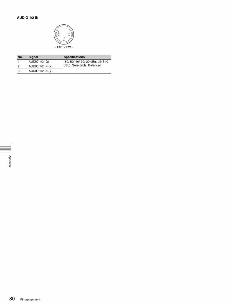
80
Appendix
AUDIO 1/2 IN
No. Signal Specifications
1 AUDIO 1/2 (G) -60/-50/-40/-30/-20 dBu, LINE (0 dBu), Selectable, Balanced2 AUDIO 1/2 IN (X)
3 AUDIO 1/2 IN (Y)
- EXT VIEW -
1
3
2
Pin assignment

Sony Corporation