hd21abe hd21abe17 - measuring instruments, … · it allows to exit from the menu or, in case of a...
TRANSCRIPT
The quality level of our instruments is the result of the continuous development of the product. This may produce some differences between the information written in this manual and the instrument you have purchased. We cannot completely exclude errors in the manual, for which we apologize. The data, images and descriptions included in this manual cannot be legally asserted. We reserve the right to make changes and corrections with no prior notice.
HD21ABE HD21ABE17
IAQ MONITOR
ENGLISH
REV. 1.1 10/06/2016

- - 2
HD21ABE Indoor Air Quality Monitor

- - 3
HD21ABE 1. Backlit graphic display. 2. ESC key: It allows to exit from the menu or, in case of a submenu, to exit from the current level
display. 3. Navigation key : It allows navigation through the menus. During normal operation, it is used
to select the resetting of the statistical data and to scroll the displayed quantities upwards. 4. Navigation key /Func: It allows navigation through the menus. In normal view, it allows to
display the statistical data: maximum, minimum, and average. 5. MEM key: It allows to start and end the recording of data (logging).
6. Navigation key : It allows navigation through the menus. During normal operation, it is used to cancel the resetting of the statistical data and to scroll the displayed quantities downwards.
7. MENU key: It allows to enter and exit the instrument’s functioning parameter setting menu. 8. Navigation key / Unit: It allows navigation through the menus. During normal operation, it
changes the unit of measurement of the displayed main quantity. 9. ENTER key: In the menu, it confirms the data entered. In normal view, it allows to reset the
statistical data. 10. ON/OFF-Auto Off key: It turns the instrument on and off. When pressed together with the
ESC key, it disables the automatic turn off.
11. USB serial port (mini-USB connector). 12. Power supply input.
- - 4
HD21ABE17 Indoor Air Quality
Monitor

- - 5
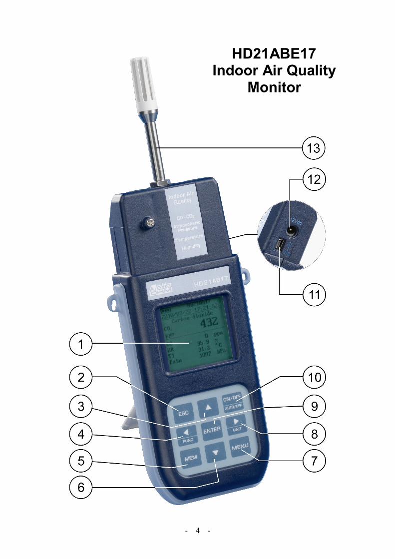
HD21ABE17 1. Backlit graphic display. 2. ESC key: It allows to exit from the menu or, in case of a submenu, to exit from the current level
display. 3. Navigation key : It allows navigation through the menus. During normal operation, it is used
to select the resetting of the statistical data and to scroll the displayed quantities upwards. 4. Navigation key /Func: It allows navigation through the menus. In normal view, it allows to
display the statistical data: maximum, minimum, and average. 5. MEM key: It allows to start and end the recording of data (logging).
6. Navigation key : It allows navigation through the menus. During normal operation, it is used to cancel the resetting of the statistical data and to scroll the displayed quantities downwards.
7. MENU key: It allows to enter and exit the instrument’s functioning parameter setting menu. 8. Navigation key / Unit: It allows navigation through the menus. During normal operation, it
changes the unit of measurement of the displayed main quantity. 9. ENTER key: In the menu, it confirms the data entered. In normal view, it allows to reset the
statistical data. 10. ON/OFF-Auto Off key: It turns the instrument on and off. When pressed together with the
ESC key, it disables the automatic turn off.
11. USB serial port (mini-USB connector). 12. Power supply input.
13. Temperature-Humidity sensors.

- - 6
TABLE OF CONTENTS
1. GENERAL CHARACTERISTICS ...................................................................................................................... 7
2. THE USER INTERFACE .................................................................................................................................... 8 2.1 THE HD21ABE DISPLAY ....................................................................................................................................... 8 2.2 THE HD21ABE17 DISPLAY ................................................................................................................................... 9 2.3 THE KEYBOARD ...................................................................................................................................................10
3. OPERATION ......................................................................................................................................................12 3.1 “/UNIT” KEY FOR THE UNIT OF MEASUREMENT ..................................................................................................13 3.2 THE MAXIMUM, MINIMUM AND AVERAGE VALUES OF THE CAPTURED QUANTITIES ...................................................13 3.3 INSTRUMENT SETUP ..............................................................................................................................................14 3.4 START OF A NEW LOGGING SESSION .......................................................................................................................14
4. MAIN MENU ......................................................................................................................................................15 4.1 INFO MENU ..........................................................................................................................................................15 4.2 LOGGING MENU ...................................................................................................................................................17
4.2.1 Log Interval .............................................................................................................................................17 4.2.2 AutoPowerOff– AutoPowerOff Mode .......................................................................................................18 4.2.3 Start/Stop Log – Automatic Start ..............................................................................................................19 4.2.4 Cancel Auto-Start ....................................................................................................................................21 4.2.5 Log File Manager ....................................................................................................................................22
4.3 SERIAL MENU (SERIAL COMMUNICATION) ............................................................................................................24 4.3.1 Print Interval ...........................................................................................................................................25
4.4 SETTINGS .............................................................................................................................................................25 4.4.1 Contrast ..................................................................................................................................................26 4.4.2 Backlight .................................................................................................................................................26
4.5 PROBES CALIBRATION ..........................................................................................................................................27 4.5.1 CO2 Calibration ......................................................................................................................................27 4.5.2 CO Calibration .......................................................................................................................................31 4.5.3 RH calibration (HD21ABE17 only) ..........................................................................................................35
4.6 LANGUAGE...........................................................................................................................................................37
5. CONNECTION TO A PC ...................................................................................................................................38 5.1 STORING AND TRANSFERRING DATA TO A PC ........................................................................................................39
5.1.1 Logging Function ....................................................................................................................................39 5.1.2 Clearing the memory ...............................................................................................................................39 5.1.3 Print function ..........................................................................................................................................40
6. INSTRUMENT SIGNALS AND FAULTS .........................................................................................................41
7. BATTERY SYMBOL – MAINS POWER SUPPLY ..........................................................................................42 7.1 BATTERIES RECHARGING ......................................................................................................................................42 7.2 NOTES FOR THE BATTERIES USE .............................................................................................................................43 7.3 REPLACEMENT OF THE BATTERY PACK ..................................................................................................................43 7.4 BATTERIES DISPOSAL ............................................................................................................................................43
8. INSTRUMENT STORAGE ................................................................................................................................44
9. TECHNICAL CHARACTERISTICS .................................................................................................................45 9.1 TECHNICAL DATA OF THE SENSORS ........................................................................................................................46
10. ORDERING CODES .........................................................................................................................................47 10.1 ACCESSORIES .....................................................................................................................................................47
10.1.1 Accessories for CO and CO2 sensors ......................................................................................................47 10.1.2 Accessories for humidity sensor .............................................................................................................47

- - 7
1. GENERAL CHARACTERISTICS
HD21ABE and HD21ABE17 IAQ Monitors are bench-top/portable instruments manufactured by Delta Ohm for the analysis of indoor air quality (IAQ, Indoor Air Quality). The instruments simultaneously measure the parameters: CO2 Carbon Dioxide, CO Carbon Monoxide and Atmospheric Pressure. The HD21ABE17 instrument also measures Temperature and Relative Humidity, and it calculates Dew Point, Wet Bulb Temperature, Absolute Humidity, Mixing Ratio and Enthalpy. HD21ABE and HD21ABE17 are dataloggers with a memory capacity of 67600 recordings, divided in 64 blocks. They use the DeltaLog10 software from version 0.1.5.3. Reference Standards: ASHRAE 62.1, Legislative Decree 81/2008. These regulations apply to all confined spaces that could be used by people. Kitchens, baths, changing rooms and swimming pools are included, due to their high humidity. You should take into account, in regard to air quality, possible chemical, physical and biological contaminants. The instruments have a wide Dot Matrix graphic display with a resolution of 160x160 dots.
The instruments typical applications are:
• Measurement of IAQ (Indoor Air Quality) and comfort conditions in schools, offices and indoor spaces.
• Analysis and study of the Sick Building Syndrome, and of the resulting consequences.
• Checking the HVAC (Heating, Ventilation and Air Conditioning) system efficiency.
• Examination of IAQ conditions in factories to optimize microclimate and improve productivity.
• Building Automation checks.

- - 8
2. THE USER INTERFACE
The user interface consist of a backlit LCD graphic display, and the power-on and setting keys. When battery powered, and not pressing any key, the backlight turns off after about 1 minute. To turn it back on, press any key. When using an external power supply, the backlight is always on. Turn the instrument on and off with the ON/OFF key. When you turn the instrument on, the logo and model will be displayed for a few seconds, and then the main display.
The quantities detected by the instrument can be viewed with a larger character size, at the top of the display. The parameter displayed with a larger character is called main quantity. In order to select the parameter to be displayed as main quantity, use the keys. For some quantities, you can select the unit of measurement; temperature can be displayed as °C or °F.
2.1 THE HD21ABE DISPLAY
HD21ABE 2010/02/10 08:00:00
Carbon DioxideCO2 600 ppm CO 0 ppmPatm 1000 hPa
1. Battery’s charge status and instrument code. In case the logging function is on, this line
shows the current logging number and the time elapsed from logging start. 2. Main quantity (in this case, CO2 Carbon Dioxide). 3. Display of all other quantities. 4. Current date and time.
The detected quantities are:
CO2 Carbon Dioxide ppm CO Carbon Monoxide ppmPatm Atmospheric Pressure hPa
1
3
4
2

- - 9
2.2 THE HD21ABE17 DISPLAY
HD21ABE17 2010/02/10 08:00:00
Carbon DioxideCO2 600 ppm CO 0 ppmPatm 1000 hPaRH 25.0 % T 17.0 °C
1. Battery’s charge status and instrument code. In case the logging function is on, this line
shows the current logging number and the time elapsed from logging start. 2. Main quantity (in this case, CO2 Carbon Dioxide). 3. Display of all other quantities. 4. Current date and time. The detected and computed quantities are:
CO2 Carbon Dioxide ppm CO Carbon Monoxide ppmRH Relative Humidity %T Temperature °C – °FPatm Atmospheric Pressure hPaTd Dew Point °C – °FTw Wet Bulb Temperature °C – °FAH Absolute Humidity g/m3
r Mixing Ratio g/kgH Enthalpy kJ/kg
1
3
4
2

- - 10
2.3 THE KEYBOARD
The keys on the instrument perform the following functions:
ON-OFF/AUTO-OFF key
It turns the instrument on and off. When turning the instrument on, the first screen will be displayed. After few seconds the measured quantities will be displayed.
+
Auto Power Off
The instrument has an AutoPowerOff function that automatically turns the instrument off after about 8 minutes if no key is pressed. The AutoPowerOff function can be disabled by holding the ESC key pressed down when turning the instrument on: the symbol will appear on the first line to remind the user that the instrument can only be turned off by pressing the ON/OFF key. The AutoPowerOff function is disabled when:
• External power is used. • During data download. • During logging.
MENU key
It allows to enter to and exit from the instrument’s functioning parameter setting menu.
ENTER key
In the menu, it confirms the entered data. During normal operation it confirms the resetting of the statistical data.
ESC key
It allows to exit from the menu or, in case of a submenu, to exit from the current level display.
MEM key
It allows to start and end a “logging” session; the data sending interval must be set in the menu.
- - 11
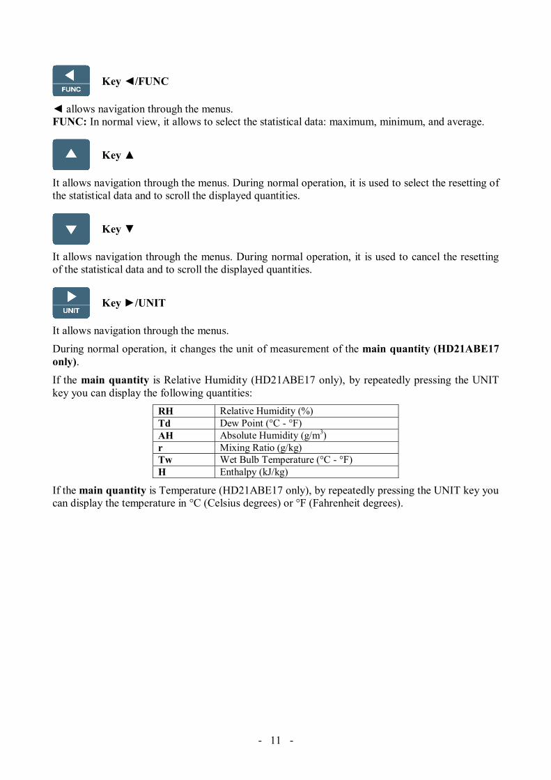
Key /FUNC
allows navigation through the menus. FUNC: In normal view, it allows to select the statistical data: maximum, minimum, and average.
Key
It allows navigation through the menus. During normal operation, it is used to select the resetting of the statistical data and to scroll the displayed quantities.
Key
It allows navigation through the menus. During normal operation, it is used to cancel the resetting of the statistical data and to scroll the displayed quantities.
Key /UNIT
It allows navigation through the menus. During normal operation, it changes the unit of measurement of the main quantity (HD21ABE17 only). If the main quantity is Relative Humidity (HD21ABE17 only), by repeatedly pressing the UNIT key you can display the following quantities:
RH Relative Humidity (%)Td Dew Point (°C - °F)AH Absolute Humidity (g/m3)r Mixing Ratio (g/kg)Tw Wet Bulb Temperature (°C - °F)H Enthalpy (kJ/kg)
If the main quantity is Temperature (HD21ABE17 only), by repeatedly pressing the UNIT key you can display the temperature in °C (Celsius degrees) or °F (Fahrenheit degrees).

- - 12
3. OPERATION
During turning on, the following message is displayed for about 10 seconds:
Model HD21ABE17 Indoor Air Quality Firm.Ver.=01.00
In addition to the Delta Ohm logo the instrument code and the firmware version are displayed.
After about 10 seconds, the measurements will appear on the display:
HD21ABE HD21ABE 2010/02/10 08:00:00 CO2: Carbon Dioxide
Carbon Dioxide CO: Carbon Monoxide CO2 600 Patm: Atmospheric Pressure ppm CO 0 ppm Patm 1000 hPa
HD21ABE17 HD21ABE17 2010/02/10 08:00:00 CO2: Carbon Dioxide
Carbon Dioxide CO: Carbon Monoxide CO2 600 Patm: Atmospheric Pressure ppm RH: Relative Humidity CO 0 ppm T: TemperaturePatm 1000 hPa RH 25.0 % T 17.0 °C

- - 13
3.1 “/UNIT” KEY FOR THE UNIT OF MEASUREMENT It allows navigation through the menus. During normal operation, it changes the unit of measurement of the main quantity (solo HD21ABE17).
If the main quantity is Relative Humidity (solo HD21ABE17), by repeatedly pressing the UNIT key you can display the following quantities:
RH Relative Humidity (%)Td Dew Point (°C - °F)AH Absolute Humidity (g/m3)r Mixing Ratio (g/kg)Tw Wet Bulb Temperature (°C - °F)H Enthalpy (kJ/kg)
If the main quantity is Temperature (solo HD21ABE17), by repeatedly pressing the UNIT key you can display the temperature in °C (Celsius degrees) or °F (Fahrenheit degrees).
3.2 THE MAXIMUM, MINIMUM AND AVERAGE VALUES OF THE CAPTURED QUANTITIES By pressing the /FUNC key you can display the maximum, minimum, average (AVG) or average in 1 minute (AVG 1min) values of the measured quantities. To reset the statistical data (except for AVG 1min function) press the /FUNC key until the “Reset? Yes No” message appears. Select Yes using the keys, and confirm with ENTER. Once selected, for example max, all displayed quantities indicate the maximum value. The AVG average is calculated on the first five minutes of samples, and then on the current average.
THE AVERAGE IN 1 MINUTE FUNCTION By pressing the /FUNC key you can select the AVG 1min (Average in 1 minute) function:
Function: AVG 1min READY 00:00:60
Carbon DioxideCO2 600 ppm CO 0 ppmPatm 1000 hPaRH 25.0 % T 17.0 °C
If the function is selected, the " READY 00:00:60 " indication on the LCD blinks to prompt the user to start the 1 minute average calculation of the acquired values.
To start the calculation, press the ENTER key. The " RUNNING " indication and a countdown will appear on the display. During calculation, the instrument continuously emits one short beep per second.

- - 14
Function: AVG 1min RUNNING 00:00:48
Carbon DioxideCO2 600 ppm CO 0 ppmPatm 1000 hPaRH 25.0 % T 17.0 °C
After 1 minute the instrument emits one long beep and displays the calculated average on the LCD.
Function: AVG 1min AVG 1min 00:00:00
Carbon DioxideCO2 602 ppm CO 0 ppmPatm 1000 hPaRH 25.0 % T 17.0 °C
The calculated average is frozen on the LCD until the ENTER key is pressed.
To escape the 1min average calculation during the countdown, press the ESC key. Note: when READY indication is displayed, the measurement values appearing on the LCD are the instant acquired values. When RUNNING indication is displayed, the measurement values appearing on the LCD are the continuously updated average values.
3.3 INSTRUMENT SETUP In order to set the instrument, you have to open the main menu by pressing MENU. See chapter 4 for further details.
3.4 START OF A NEW LOGGING SESSION Press MEM to start a Logging session: This key starts and stops the logging of a data block to be saved in the instrument’s internal memory. The data logging frequency is set in the “Log Frequency” menu parameter. The data logged between a start and subsequent stop represent a measurement block.
When the logging function is on, the LOG indication and the logging session number are displayed; a beep is issued each time a logging occurs.
To end the logging, press MEM again. The instrument can turn off during logging between one capture and the next: The function is controlled by the AutoPowerOff parameter. When the logging interval is less than 5 minutes, the logging instrument remains on; with an interval of at least 5 minutes, it turns off between one capture and the next.
- - 15
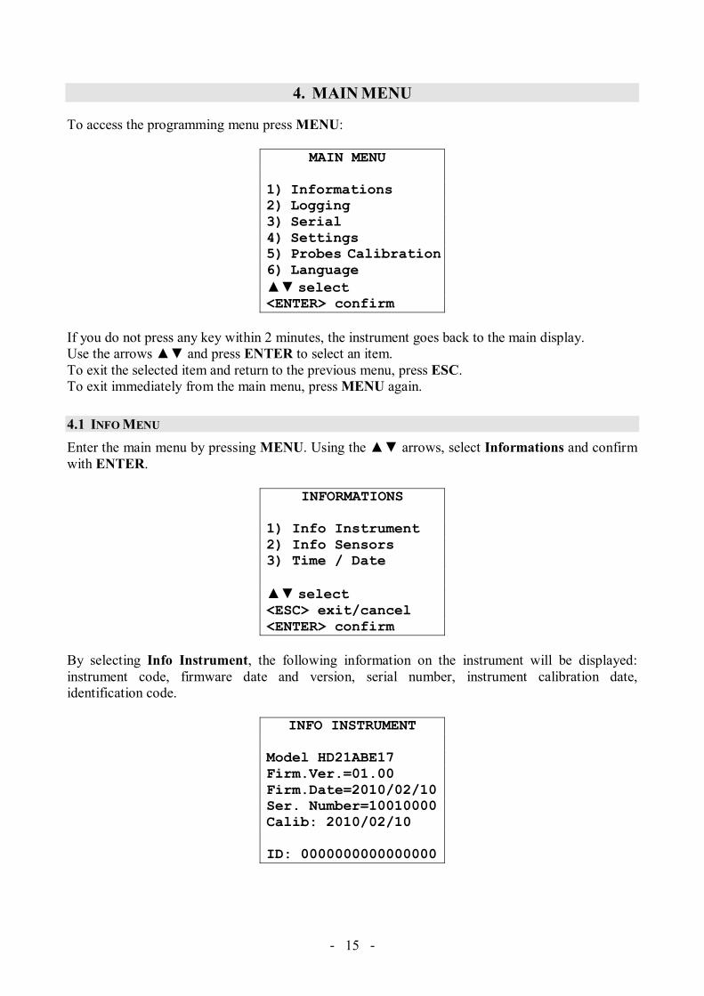
4. MAIN MENU
To access the programming menu press MENU:
MAIN MENU 1) Informations2) Logging 3) Serial4) Settings 5) Probes Calibration6) Language select <ENTER> confirm
If you do not press any key within 2 minutes, the instrument goes back to the main display. Use the arrows and press ENTER to select an item. To exit the selected item and return to the previous menu, press ESC. To exit immediately from the main menu, press MENU again.
4.1 INFO MENU Enter the main menu by pressing MENU. Using the arrows, select Informations and confirm with ENTER.
INFORMATIONS 1) Info Instrument 2) Info Sensors 3) Time / Date select <ESC> exit/cancel<ENTER> confirm
By selecting Info Instrument, the following information on the instrument will be displayed: instrument code, firmware date and version, serial number, instrument calibration date, identification code.
INFO INSTRUMENT
Model HD21ABE17 Firm.Ver.=01.00 Firm.Date=2010/02/10Ser. Number=10010000Calib: 2010/02/10 ID: 0000000000000000

- - 16
To change the ID, press ENTER. Use the arrows to select the item, and edit it with the arrows. Proceed with the other items, and finally confirm with ENTER. By selecting Info Sensors, the following information on the sensors will be displayed:
INFO SENSORS
Type= CO2-CO Fw.V0R0Cal = 2010/02/10 SN = 10010000
INFO SENSORS: Firmware type and version. Calibration date. Serial number of the sensors board. Press ESC to return to the main menu. Press MENU to exit the menu.
Time/Date allows setting the date and time that will be shown at the top of the display. To access the Time/Date submenu, proceed as follows: 1. Use the arrows to select Time/Date; 2. Press ENTER; 3. You will get the following message
TIME / DATE
year/mm/dd hh:mm2010/02/10 08:00:00 set 00 seconds! select set <ENTER> confirm
4. Use the arrows to select the data to be set (year/month/day and hour:minutes); 5. Once selected, the data will start blinking; 6. Use the arrows to enter the correct value; 7. Press ENTER to confirm and return to the main menu; 8. Or press ESC to return to the menu without making any change; 9. Press MENU to exit immediately from the main menu.
NOTE: In regard to the time, you can set hours and minutes. The seconds are always set to 00 (set 00 seconds!).

- - 17
4.2 LOGGING MENU Enter the main menu by pressing MENU;
• Use the arrows to select Logging; • Press ENTER: The parameter setting submenu for the logging sessions (to be captured) will
be displayed.
LOGGING MENU
1) Log frequency2) Auto switch off3) Start/Stop Log4) Start Log Erase5) Log File Manager select <ENTER> confirm
4.2.1 Log Interval Use this item to set the LOG interval (interval between two subsequent sample captures): To enter this setting, proceed as follows: Once you have accessed the LOGGING submenu (previous par.) use the arrows to select Log frequency:
LOGGING MENULOG FREQUENCY
Insert interval of memorization h:mm:ss (1h max) 0:00:15 set <ENTER> confirm
1. Use the arrows to select the interval duration from a minimum of 15 seconds to a maximum
of one hour; 2. Press ENTER to confirm and return to the Logging menu; 3. Press ESC to return to the Logging menu without making any change; 4. Press ESC again to return to the main menu; 5. Press MENU to exit immediately from the menu.
These are the available values: 15 seconds - 30 seconds - 1 minute - 2 minutes - 5 minutes - 15 minutes - 20 minutes - 30 minutes - 1 hour
Logging interval Storage capacity Logging
interval Storage capacity 15 seconds About 11 days and 17 hours 15 minutes About 1 year and 339 days 30 seconds About 23 days and 11 hours 20 minutes About 2 years and 208 days1 minute About 46 days and 22 hours 30 minutes About 3 years and 313 days2 minutes About 93 days and 21 hours 1 hour About 7 years and 261 days5 minutes About 234 days and 17 hours
- - 18
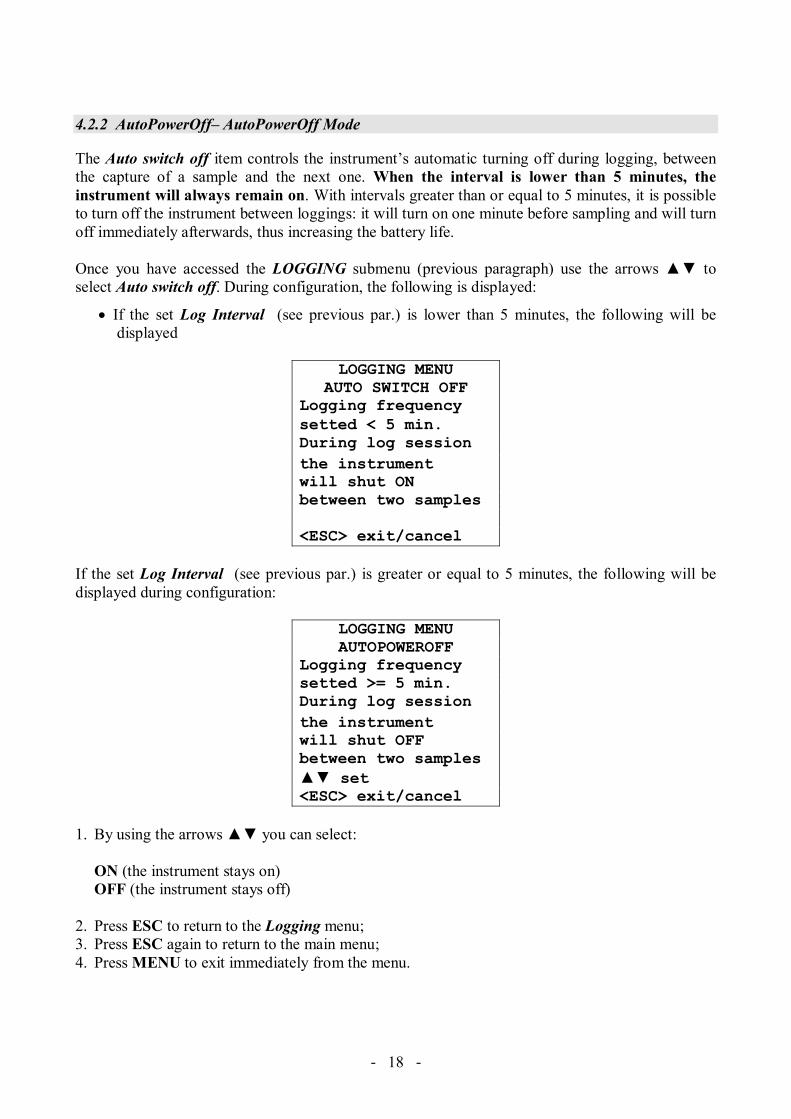
4.2.2 AutoPowerOff– AutoPowerOff Mode
The Auto switch off item controls the instrument’s automatic turning off during logging, between the capture of a sample and the next one. When the interval is lower than 5 minutes, the instrument will always remain on. With intervals greater than or equal to 5 minutes, it is possible to turn off the instrument between loggings: it will turn on one minute before sampling and will turn off immediately afterwards, thus increasing the battery life. Once you have accessed the LOGGING submenu (previous paragraph) use the arrows to select Auto switch off. During configuration, the following is displayed:
• If the set Log Interval (see previous par.) is lower than 5 minutes, the following will be displayed
LOGGING MENU
AUTO SWITCH OFF Logging frequency setted < 5 min. During log session the instrument will shut ON between two samples <ESC> exit/cancel
If the set Log Interval (see previous par.) is greater or equal to 5 minutes, the following will be displayed during configuration:
LOGGING MENU AUTOPOWEROFF
Logging frequency setted >= 5 min. During log session the instrument will shut OFF between two samples set <ESC> exit/cancel
1. By using the arrows you can select:
ON (the instrument stays on) OFF (the instrument stays off)
2. Press ESC to return to the Logging menu; 3. Press ESC again to return to the main menu; 4. Press MENU to exit immediately from the menu.
- - 19
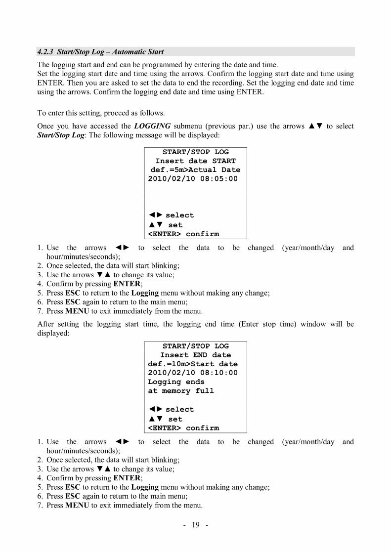
4.2.3 Start/Stop Log – Automatic Start The logging start and end can be programmed by entering the date and time. Set the logging start date and time using the arrows. Confirm the logging start date and time using ENTER. Then you are asked to set the data to end the recording. Set the logging end date and time using the arrows. Confirm the logging end date and time using ENTER.
To enter this setting, proceed as follows.
Once you have accessed the LOGGING submenu (previous par.) use the arrows to select Start/Stop Log: The following message will be displayed:
START/STOP LOG Insert date START def.=5m>Actual Date2010/02/10 08:05:00 select set <ENTER> confirm
1. Use the arrows to select the data to be changed (year/month/day and hour/minutes/seconds);
2. Once selected, the data will start blinking; 3. Use the arrows to change its value; 4. Confirm by pressing ENTER; 5. Press ESC to return to the Logging menu without making any change; 6. Press ESC again to return to the main menu; 7. Press MENU to exit immediately from the menu. After setting the logging start time, the logging end time (Enter stop time) window will be displayed:
START/STOP LOG Insert END date
def.=10m>Start date 2010/02/10 08:10:00 Logging ends at memory full
select set <ENTER> confirm
1. Use the arrows to select the data to be changed (year/month/day and hour/minutes/seconds);
2. Once selected, the data will start blinking; 3. Use the arrows to change its value; 4. Confirm by pressing ENTER; 5. Press ESC to return to the Logging menu without making any change; 6. Press ESC again to return to the main menu; 7. Press MENU to exit immediately from the menu.

- - 20
8. Once both values have been set, a summary will be displayed showing the start and end time of the LOG session.
LOGGING MENU SETTED LOG
START Date2010/02/10 10:29:00 END Date2010/02/10 10:39:00 <ESC> exit/cancel<ENTER> confirm
9. Press ENTER to confirm or ESC to exit without enabling the automatic start: In both cases, you
will return to the LOGGING menu. 10. Press MENU to exit immediately from the main menu. When the instrument starts automatically a LOG session, a beep is issued on each capture and the blinking LOG message is shown at the top of the display. Press MEM to stop the session before the set time. To cancel the automatic start setting, use the Start Log Erase function as illustrated in the following paragraph. NOTE: The automatic logging session is started even when the instrument is off. If it is off when the automatic logging session is started, the instrument, even if powered by the mains, is turned on few seconds earlier and remains on at the end of logging. If it is powered by the battery, it is turned on and off at each data capture, except when the interval is lower than 5 minutes. At the end of logging, it is turned off for good. See paragraph 4.2.2 to set the automatic shut off.

- - 21
4.2.4 Cancel Auto-Start Once the LOG session start and end times are set, you can inhibit the session automatic start by using Start Log Erase. Once you have accessed the LOGGING submenu: 1. Use the arrows to select Start Log Erase 2. The LOG session start and end times will be displayed:
MENU LOGGING Auto-Start Erase
Setted start:2010/02/10 10:29:00 Setted end:2010/02/10 10:39:00 Press for Auto-Start Erase <ENTER> confirm
3. By pressing the following message will be displayed: LOGGING MENU
Auto-Start not active
<ESC> exit/cancel <ENTER> confirm
4. Press ENTER to cancel the automatic start; 5. Press ESC to exit without cancelling the automatic start; 6. Press ESC again to exit from the submenus; 7. Or press MENU to exit immediately from the main menu. See the previous paragraph to set a new automatic start time after cancelling the previous one.
- - 22
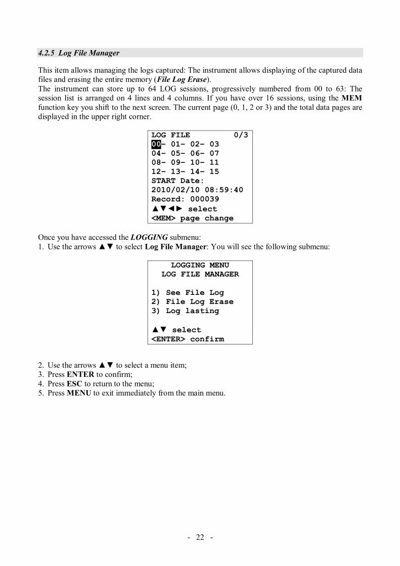
4.2.5 Log File Manager
This item allows managing the logs captured: The instrument allows displaying of the captured data files and erasing the entire memory (File Log Erase). The instrument can store up to 64 LOG sessions, progressively numbered from 00 to 63: The session list is arranged on 4 lines and 4 columns. If you have over 16 sessions, using the MEM function key you shift to the next screen. The current page (0, 1, 2 or 3) and the total data pages are displayed in the upper right corner.
LOG FILE 0/300– 01– 02– 03 04– 05– 06– 07 08– 09– 10– 11 12– 13– 14– 15 START Date: 2010/02/10 08:59:40 Record: 000039 select <MEM> page change
Once you have accessed the LOGGING submenu: 1. Use the arrows to select Log File Manager: You will see the following submenu:
LOGGING MENU LOG FILE MANAGER
1) See File Log2) File Log Erase3) Log lasting select <ENTER> confirm
2. Use the arrows to select a menu item; 3. Press ENTER to confirm; 4. Press ESC to return to the menu; 5. Press MENU to exit immediately from the main menu.

- - 23
See File Log: Selecting this item you can view the logging sessions in the instrument:
LOG FILE 0/300– 01– 02– 03 04– 05– 06– 07 08– 09– 10– 11 12– 13– 14– 15 START Date: 2010/02/10 08:50:40 Record: 000039 select <MEM> page change
1. Use the arrows to select the log, and the MEM key to shift page. 2. Once a file is selected, the acquisition start date and time and the number of samples contained in
the file (Rec) are displayed at the bottom of the display. The files are stored in ascending order. Each file is only identified by the date and time, shown on the display. In the example above, the file 00 is selected: The recording started at 08:50:40 on 10 February 2010. The file contains 39 samples.
3. press ESC to exit this menu; 4. Press MENU to exit immediately from the main menu.
File Log Erase (erasing all memory) By selecting this item, the “ERASE ALL LOGS SETTED FILES” message will be displayed:
MENU LOGGING MENU LOGGING ERASE ALL LOGS ERASE ALL LOGS SETTED FILES SETTED FILES
EMPTY MEMORY <MEM> confirm <Esc> exit <Esc> exit
1. Press MEM to erase all files; 2. Press ESC to cancel the operation and return to the previous menu level; 3. Press MENU to exit immediately from the main menu.

- - 24
Log lasting (time set for recording) It represents the recording duration: After this set time, the recording is ended. The recording can be stopped earlier by pressing MEM. To disable this function, set the time to 0:00:00. In this case the recording ends by pressing MEM or when the memory is full.
LOGGING MENU LOG LASTING
h:mm:ss (1h max) 00:00:00 With setting: 00:00:00 Log stop with key MEM set <ESC> exit
Use the arrows to change the set time; the maximum allowed value is 1 hour. Confirm with ENTER. Press ESC to exit from this menu level without making changes. Press MENU to exit immediately from the main menu.
4.3 SERIAL MENU (SERIAL COMMUNICATION) The Serial submenu allows setting the record printing interval (ri eral). The LOG sessions can be downloaded on a PC, through the USB connection. The transfer speed is fixed at 460800 bps. After downloading the data on the PC, using the dedicated software, they will be processed by this software for graphic display. To access the Serial submenu, proceed as follows: 1. Press MENU on the instrument; 2. Use the arrows to select Serial; 3. Press ENTER; 4. You will get the Serial submenu.
COMMUNICATION MENU SERIAL
1) Print Interval select <ESC> exit/cancel<ENTER> confirm
- - 25
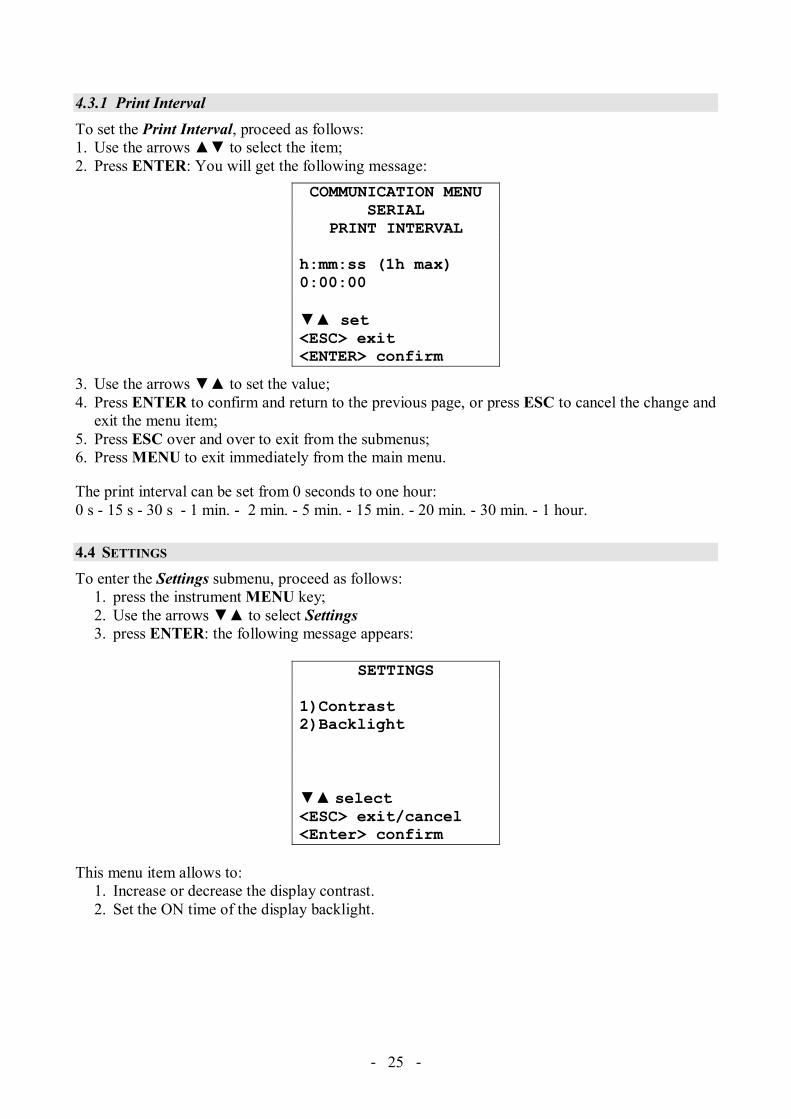
4.3.1 Print Interval To set the Print Interval, proceed as follows: 1. Use the arrows to select the item; 2. Press ENTER: You will get the following message:
COMMUNICATION MENU SERIAL
PRINT INTERVAL h:mm:ss (1h max) 0:00:00
set <ESC> exit<ENTER> confirm
3. Use the arrows to set the value; 4. Press ENTER to confirm and return to the previous page, or press ESC to cancel the change and
exit the menu item; 5. Press ESC over and over to exit from the submenus; 6. Press MENU to exit immediately from the main menu.
The print interval can be set from 0 seconds to one hour: 0 s - 15 s - 30 s - 1 min. - 2 min. - 5 min. - 15 min. - 20 min. - 30 min. - 1 hour.
4.4 SETTINGS To enter the Settings submenu, proceed as follows:
1. press the instrument MENU key; 2. Use the arrows to select Settings 3. press ENTER: the following message appears:
SETTINGS
1)Contrast 2)Backlight select <ESC> exit/cancel <Enter> confirm
This menu item allows to:
1. Increase or decrease the display contrast. 2. Set the ON time of the display backlight.

- - 26
4.4.1 Contrast This item of the Settings menu allows to increase or decrease the display contrast. To access the Contrast submenu, proceed as follows:
1. Use the arrows to select Contrast; 2. Press ENTER 3. You will get the following message
CONTRAST LCD
Contrast set:
012
set <ESC> exit/cancel
4. Use the arrows to decrease or increase the contrast; 5. Press ENTER or ESC to return to the main menu; 6. Press MENU to exit immediately from the main menu.
4.4.2 Backlight This item of the Settings menu allows to set the ON time for the display backlight. To enter the Backlight submenu, proceed as follows:
1. Using the arrows select Backlight. 2. Press ENTER 3. The following message appears:
BACKLIGHT
1) Always switch on 2) 5 seconds 3) 15 seconds 4) 30 seconds select <ESC> exit/cancel <Enter> confirm
4. Use the arrows to select the desired option 5. Press ENTER to confirm or press ESC more times to escape from the various menu levels 6. Press MENU to exit directly form the main menu.

- - 27
4.5 PROBES CALIBRATION
The instruments and sensors are calibrated in the factory; no calibration is usually required by the user. However, you can perform a new calibration.
You can perform the calibration of the CO (Carbon Monoxide) and CO2 (Carbon Dioxide) sensors. With the HD21ABE17 instrument you can also perform the calibration of the RH (Relative Humidity) sensor.
No calibration is allowed for the Temperature sensor (HD21ABE17). To calibrate the probes correctly, a knowledge of and abiding by the physical phenomena on which the measurement is based is fundamental: this is the reason why it is recommended to abide by what is reported below carefully and only to perform new calibrations if technically proficient.
PROBES CALIBRATION
1) Calibration CO2 2) Calibration CO 3) Calibration RH select <ESC> exit/cancel<ENTER> confirm
4.5.1 CO2 Calibration
Use the arrows to select the 1) Calibration CO2 item:
PROBES CALIBRATION
1) Calibration CO2 2) Calibration CO3) Calibration RH select <ESC> exit/cancel<ENTER> confirm
Confirm with ENTER. The following screen will appear:

- - 28
PROBE CALIBRATIONCALIBRATION CO2
1) Offset only calib2) 2 Pts Calibration3) Restore Fact cal select <ESC> exit/cancel<ENTER> confirm
The CO2 sensor can be calibrated:
• In 1 point: only the sensor offset is corrected, the point can be any value between 0 and 950 ppm.
• In 2 points: the sensor offset and slope are corrected, the lower point can be any value between 0 and 950 ppm, the upper point can be any value between 1000 ppm and the full scale of the instrument.
1 point calibration: 1. Place the instrument in an environment with known CO2
concentration between 0 and 950 ppm (for ex. in clean air). For 0 ppm calibration with nitrogen bottle (code MINICAN.12A), slide the HD21AB17.9 accessory on the top of the instrument and connect the tube from the nitrogen bottle to the CO2 input of the accessory; adjust the bottle flow meter to get a constant flow from 0.3 to 0.5 l/min.
2. Wait about 15 minutes before continuing.
3. When the measurement is stable, select the 1) Offset only calib calibration option.
4. The instrument display shows the measured CO2. CALIBRATION CO2
OFFSET CALIBRATION START CALIBRATION
CO2 450 ppm <ESC> exit/cancel<ENTER> confirm
5. Adjust the value by using the arrows . 6. Press ENTER on the instrument and wait the time necessary
for calibration without changing the working conditions. 7. When the “CALIBRATION GOOD” indication appears, press
ESC to return to the calibration menu.

- - 29
8. If the nitrogen bottle was used, close the bottle valve, remove the tube from the HD21AB17.9 accessory and remove the accessory from the instrument.
Calibrazione in 2 punti: 1. Place the instrument in an environment with known CO2 concentration between 0 and 950 ppm
(for ex. in clean air). For 0 ppm calibration with nitrogen bottle (code MINICAN.12A), slide the HD21AB17.9 accessory on the top of the instrument and connect the tube from the nitrogen bottle to the CO2 input of the accessory; adjust the bottle flow meter to get a constant flow from 0.3 to 0.5 l/min.
2. Wait about 15 minutes before continuing.
3. Select the 2) 2 Pts Calibration calibration option. 4. Select 1) Calib lower point.
PROBE CALIBRATIONCALIBRATION CO2 2 PTS CO2 CALIB
1) Calib lower point2) Calib upper point select <ESC> exit/cancel<ENTER> confirm
5. The instrument display shows the measured CO2. 2 PTS CO2 CALIB LOWER POINT
START CALIBRATION CO2 450 ppm <ESC> exit/cancel<ENTER> confirm
6. Adjust the value by using the arrows . 7. Press ENTER on the instrument and wait the time necessary for calibration without changing
the working conditions. 8. When the “CALIBRATION GOOD” indication appears, press ESC to return to the calibration
menu.
9. If the nitrogen bottle was used, close the bottle valve, remove the tube from the HD21AB17.9 accessory and remove the accessory from the instrument.
10. Place the instrument in an environment with known CO2 concentration between 1000 ppm and the full scale of the instrument.
11. Wait about 15 minutes before continuing.
12. Select 2) Calib upper point. 13. The instrument display shows the measured CO2.

- - 30
14. Adjust the value by using the arrows .
15. Press ENTER on the instrument and wait the time necessary for calibration without changing the working conditions.
16. When the “CALIBRATION GOOD” indication appears, press ESC to return to the calibration menu.
Restoring the factory CO2 calibration: In case of erroneous execution of the calibration procedure, it is always possible to get back to the factory calibration by selecting the 3) Restore Fact cal calibration option.
- - 31
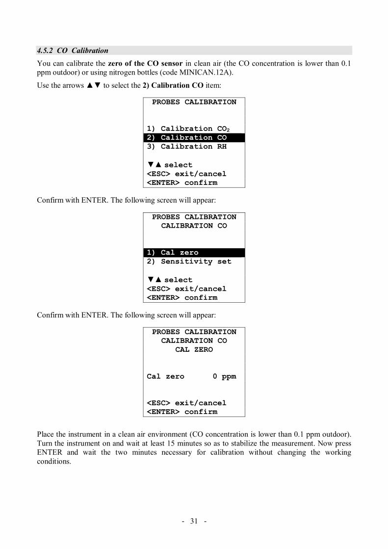
4.5.2 CO Calibration You can calibrate the zero of the CO sensor in clean air (the CO concentration is lower than 0.1 ppm outdoor) or using nitrogen bottles (code MINICAN.12A).
Use the arrows to select the 2) Calibration CO item:
PROBES CALIBRATION
1) Calibration CO2 2) Calibration CO 3) Calibration RH select <ESC> exit/cancel<ENTER> confirm
Confirm with ENTER. The following screen will appear:
PROBES CALIBRATIONCALIBRATION CO
1) Cal zero2) Sensitivity set select <ESC> exit/cancel<ENTER> confirm
Confirm with ENTER. The following screen will appear:
PROBES CALIBRATIONCALIBRATION CO
CAL ZERO
Cal zero 0 ppm <ESC> exit/cancel<ENTER> confirm
Place the instrument in a clean air environment (CO concentration is lower than 0.1 ppm outdoor). Turn the instrument on and wait at least 15 minutes so as to stabilize the measurement. Now press ENTER and wait the two minutes necessary for calibration without changing the working conditions.

- - 32
CO zero calibration with nitrogen bottle (code MINICAN.12A):
Using a screwdriver, open the back small door of the instrument. Connect the tube from the MINICAN.12A bottle with the rubber cap on the CO sensor head.
Use the arrows to select the 2) Calibration CO item:
PROBES CALIBRATION
1) Calibration CO2 2) Calibration CO 3) Calibration RH select <ESC> exit/cancel<ENTER> confirm
Confirm with ENTER. The following screen will appear:
PROBES CALIBRATIONCO CALIBRATION
1) Cal zero2) Sensitivity set select <ESC> exit/cancel<ENTER> confirm
Back door CO sensor

- - 33
Confirm with ENTER. The following screen will appear:
PROBES CALIBRATIONCO CALIBRATION
CAL ZERO
Cal zero 0 ppm <ESC> exit/cancel<ENTER> confirm
• Wait about 15 minutes before continuing. • Supply the gas adjusting the bottle flow meter to get a constant flow from 0.1 to 0.2 l/min. • Press ENTER and wait the two minutes necessary for calibration without changing the
working conditions. • At the end, close the bottle spigot and remove the cap from the CO sensor. • Insert the protection grid.
Sensitivity of the CO sensor: The sensitivity in nA/ppm of the CO sensor is already set at the factory. If you need to chage it, follow this procedure:
1. Use the arrows to select the 2) Calibration CO item:
PROBES CALIBRATION
1) Calibration CO2 2) Calibration CO 3) Calibration RH select <ESC> exit/cancel<ENTER> confirm
2. Confirm with ENTER. The following screen will appear:
PROBES CALIBRATIONCALIBRATION CO
1) Cal zero2) Set sensitivity select <ESC> exit/cancel<ENTER> confirm
- - 34
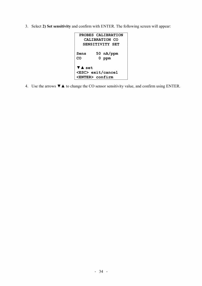
3. Select 2) Set sensitivity and confirm with ENTER. The following screen will appear:
PROBES CALIBRATIONCALIBRATION CO SENSITIVITY SET
Sens 50 nA/ppm CO 0 ppm set <ESC> exit/cancel<ENTER> confirm
4. Use the arrows to change the CO sensor sensitivity value, and confirm using ENTER.

- - 35
4.5.3 RH calibration (HD21ABE17 only) This procedure applies to HD21ABE17 instrument. Before starting the calibration operation, you should check if you need a new calibration using the saturated solutions at 75.4%RH and 33%RH: You should proceed with the calibration, only if you find an error in one of the two above calibration points.
The calibration procedure removes the previous calibration data. For a correct calibration of the sensor, the first point should be 75%RH and the second point 33%RH. Use the arrows to select the 3) Calibration RH item:
PROBES CALIBRATION
1) Calibration CO2 2) Calibration CO 3) Calibration RH select <ESC> exit/cancel<ENTER> confirm
Confirm with ENTER. The following screen will appear: PROBES CALIBRATIONCALIBRATION RH
1) Cal RH 75%2) Cal RH 33% select <ESC> exit/cancel<ENTER> confirm
1. Use the arrows to select the 1) RH Cal 75% item; you will get the following page: PROBES CALIBRATIONCALIBRATION RH
CAL RH 75%
Actual T = 22.0°C Actual RH = 28.1%RH 75% = 70.2% set <ESC> exit/cancel<ENTER> confirm
2. Use the arrows to enter the RH 75% nominal value.
3. Check that the salt solution container contains simultaneously: • Salt in solid state • Liquid solution and wet salt.
- - 36
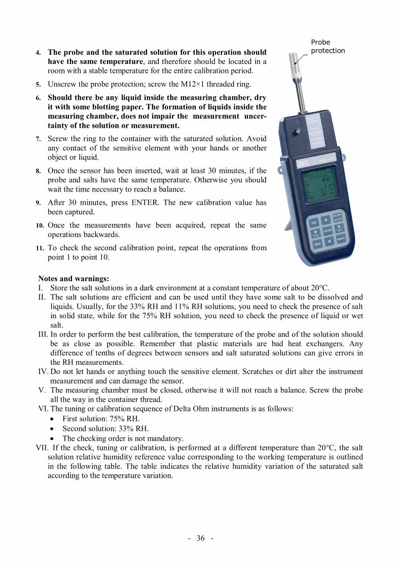
4. The probe and the saturated solution for this operation should have the same temperature, and therefore should be located in a room with a stable temperature for the entire calibration period.
5. Unscrew the probe protection; screw the M12×1 threaded ring.
6. Should there be any liquid inside the measuring chamber, dry it with some blotting paper. The formation of liquids inside the measuring chamber, does not impair the measurement uncer-tainty of the solution or measurement.
7. Screw the ring to the container with the saturated solution. Avoid any contact of the sensitive element with your hands or another object or liquid.
8. Once the sensor has been inserted, wait at least 30 minutes, if the probe and salts have the same temperature. Otherwise you should wait the time necessary to reach a balance.
9. After 30 minutes, press ENTER. The new calibration value has been captured.
10. Once the measurements have been acquired, repeat the same operations backwards.
11. To check the second calibration point, repeat the operations from point 1 to point 10.
Notes and warnings: I. Store the salt solutions in a dark environment at a constant temperature of about 20°C. II. The salt solutions are efficient and can be used until they have some salt to be dissolved and
liquids. Usually, for the 33% RH and 11% RH solutions, you need to check the presence of salt in solid state, while for the 75% RH solution, you need to check the presence of liquid or wet salt.
III. In order to perform the best calibration, the temperature of the probe and of the solution should be as close as possible. Remember that plastic materials are bad heat exchangers. Any difference of tenths of degrees between sensors and salt saturated solutions can give errors in the RH measurements.
IV. Do not let hands or anything touch the sensitive element. Scratches or dirt alter the instrument measurement and can damage the sensor.
V. The measuring chamber must be closed, otherwise it will not reach a balance. Screw the probe all the way in the container thread.
VI. The tuning or calibration sequence of Delta Ohm instruments is as follows: • First solution: 75% RH. • Second solution: 33% RH. • The checking order is not mandatory.
VII. If the check, tuning or calibration, is performed at a different temperature than 20°C, the salt solution relative humidity reference value corresponding to the working temperature is outlined in the following table. The table indicates the relative humidity variation of the saturated salt according to the temperature variation.
Probe protection

- - 37
Relative Humidity Balance values of some saturated salt solutions from 0°C to 100°C
Temp. °C Lithium chloride Magnesium chloride Sodium chloride 0 11.23 ± 0.54 33.66 ± 0.33 75.51 ± 0.34 5 11.26 ± 0.47 33.60 ± 0.28 75.65 ± 0.27 10 11.29 ± 0.41 33.47 ± 0.24 75.67 ± 0.22 15 11.30 ± 0.35 33.30 ± 0.21 75.61 ± 0.18 20 11.31 ± 0.31 33.07 ± 0.18 75.47 ± 0.14 25 11.30 ± 0.27 32.78 ± 0.16 75.29 ± 0.12 30 11.28 ± 0.24 32.44 ± 0.14 75.09 ± 0.11 35 11.25 ± 0.22 32.05 ± 0.13 74.87 ± 0.12 40 11.21 ± 0.21 31.60 ± 0.13 74.68 ± 0.13 45 11.16 ± 0.21 31.10 ± 0.13 74.52 ± 0.16 50 11.10 ± 0.22 30.54 ± 0.14 74.43 ± 0.19 55 11.03 ± 0.23 29.93 ± 0.16 74.41 ± 0.24 60 10.95 ± 0.26 29.26 ± 0.18 74.50 ± 0.30 65 10.86 ± 0.29 28.54 ± 0.21 74.71 ± 0.37 70 10.75 ± 0.33 27.77 ± 0.25 75.06 ± 0.45 75 10.64 ± 0.38 26.94 ± 0.29 75.58 ± 0.55 80 10.51 ± 0.44 26.05 ± 0.34 76.29 ± 0.65 85 10.38 ± 0.51 25.11 ± 0.39 90 10.23 ± 0.59 24.12 ± 0.46 95 10.07 ± 0.67 23.07 ± 0.52
100 9.90 ± 0.77 21.97 ± 0.60
4.6 LANGUAGE It sets the language used by the instrument. Using the arrows, select the desired language and confirm with ENTER.
LANGUAGE
1) Italiano 2) English 3) Français 4) Español 5) Deutsch select <ESC> exit/cancel<ENTER> confirm

- - 38
5. CONNECTION TO A PC
HD21ABE and HD21ABE17 are fitted with an USB 2.0 interface. Optionally, you can receive on request the serial connection cable CP23 with mini-USB connector on instrument’s side and USB 2.0 connector on computer’s side. The instruments are supplied with the DeltaLog10 software (from version 0.1.5.3) running in a Windows® operating environment. The software manages the connection, data transfer, graphic presentation, and printing operations of the captured or logged measurements.
The USB connection requires the previous installation of the driver saved on the CD-ROM of the instrument software. Install the driver before connecting the USB cable to the PC.
Standard parameters of the instrument serial transmission are: • Baud rate 460800 baud • Parity None • N. bit 8 • Stop bit 1 • Protocol Xon/Xoff
The USB 2.0 connection does not require the setting of parameters. The instruments are provided with a complete set of commands and data queries to be sent via the PC. All the commands transferred to the instrument must have the following structure:
XXCR where XX is the command code and CR is the Carriage Return (ASCII 0D)
The XX command characters are exclusively upper case characters. Once a correct command is entered, the instrument responds with “&”; when any wrong combination of characters is entered, the instrument responds with “?”. The instrument response strings end with the sending of the CR command (Carriage Return) and LF (Line Feed). Before sending commands to the instrument via the serial port, locking the keyboard to avoid functioning conflicts is recommended: Use the P0 command. When complete, restore the keyboard with the P1 command.
Command Response DescriptionP0 & Ping (locks the instrument keyboard for 70 seconds) P1 & Unlocks the instrument keyboardS0
G0 Model HD21ABE17 Instrument modelG1 M=Indoor Air Quality Model descriptionG2 SN=12345678 Instrument serial numberG3 Firm.Ver.=01.00 Firmware versionG4 Firm.Date=2010/02/10 Firmware dateG5 cal 2010/02/10 10:30:00 Calibration date and timeC1 RH-T probe type, serial number, calibration date C2 CO-CO2 probe type, serial number, calibration date GC Print instrument’s headingGB ID=0000000000000000 User code (set with T2xxxxxxxxxxxxxxxx) HA Print the current data measurement LR Print the instrument memory mapKInn Print the information of Loggging nn KRaaaa Print the recorded data in page aaaa

- - 39
Command Response DescriptionKE & Stop the data downloadLE & Erase stored dataK1 & Immediate printing of dataK0 & Stop printing dataK4 & Start logging dataK5 & Stop logging dataKP & Auto-power-off function = ENABLE KQ & Auto-power-off function = DISABLE WC0 & Setting SELF offWC1 & Setting SELF onRA Sample print = 0sec Reading of PRINT interval set and label of the
measurementsRL Sample log = 30sec Reading of LOG interval setWA# & Setting PRINT interval.
# is a hexadecimal number 0…D that represents the position of the interval in the list 0, 1, 5, 10, …, 3600 seconds.
WL# & Setting LOG interval. # is a hexadecimal number 1…D that represents the position of the interval in the list 15, …, 3600 seconds.
5.1 STORING AND TRANSFERRING DATA TO A PC
It is possible to store the measured values in the internal memory using the Logging function (MEM key). If necessary, the data stored in the memory can be transferred later to a PC.
5.1.1 Logging Function The Logging function allows recording of the measurements. The time interval between two consecutive measurements can be set from 15 seconds to 1 hour. The logging starts by pressing the MEM key and ends by pressing the same key again: The data memorized in this way form a continuous block of data. See the description of the menu items on chapter “4. MAIN MENU”. If the automatic turning off option between two recordings (see par. 4.2.2 AutoPowerOff– AutoPowerOff Mode) is enabled, upon pressing the MEM key the instrument logs the first data and turns off. 1 minute before the next logging instant, it turns on again to capture the new sample, and then turns off. The data stored in the memory can be transferred to a PC through the DeltaLog10 software (from version 0.1.5.3). During data transfer the display shows the message DUMP; to stop the data transfer press ESC on the instrument or on the PC.
5.1.2 Clearing the memory To clear the memory use the Erase Log function (see par. 4.2.5 Log File Manager). The instrument starts clearing the internal memory; at the end of the operation, it goes back to normal display.
NOTES: • Data transfer does not cause the memory to be erased: The operation can be repeated as many
times as required. • The stored data remain in the memory independently of the battery charge conditions. • The direct connection between instrument and printer via a USB connector does not work.

- - 40
• Some keys are disabled during logging. The following keys are enabled: MEM, MENU, ENTER and ESC.
• Pressing the MEM and MENU keys has no effect on the logged data if these keys are pressed after starting the recording, otherwise the following is valid.
5.1.3 Print function Press ENTER to send the measured data directly to the USB port, in real time. The printed data units of measurements are the same as those used on the display. The function is started by pressing ENTER. The time interval between two consecutive prints can be set from 15 second to 1 hour (please see the Print interval menu item at par. 4.3.1 Print Interval). If the print interval is equal to 0, by pressing ENTER a single data is sent to the connected device. If the print interval is higher than 0, the data transfer continues until the operator stops it by pressing ENTER again.

- - 41
6. INSTRUMENT SIGNALS AND FAULTS The following table lists all error indications and information displayed by the instrument and supplied to the user in different operating situations:
Display indication Explanation
- - - - This appears if the sensor relevant to the indicated physical quantity is not present or is faulty.
OVFL Overflow appears when the probe detects a value that exceeds the expected measurement range.
UFL Underflow appears when the probe detects a lower value than the expected measurement range.
MEMORY FULL!! The instrument cannot store further data, the memory space is full.
LOG It indicates that a logging session is running.

- - 42
7. BATTERY SYMBOL – MAINS POWER SUPPLY The meter is provided with a pack of 4 x 1.2V-2200mA/h Ni-MH rechargeable batteries, placed in the battery compartment.
The battery symbol on the display constantly shows the battery charge status. To the extent that batteries have discharged, the symbol "empties". When the charge decreases still further it starts blinking.
In this case, batteries should be replaced as soon as possible. If you continue to use it, the instrument can no longer ensure correct measurement and turns off. Data stored on memory will remain. The battery symbol becomes [≈] when the external power supply is connected and the batteries charging process is ended. The instrument can be powered by the mains using, for example, the stabilized power supply SWD10 input 100÷240 Vac output 12 Vdc – 1000mA. The power supply positive (pole) must be connected to the central pin.
The external power supply connector has an external diameter of 5.5mm and an internal diameter of 2.1mm.
Warning: The power supply has a double function: it powers the meter and recharge the Ni-MH battery pack.
7.1 BATTERIES RECHARGING
To recharge the battery pack use the SWD10 battery charger supplied with the instrument. Proceed as follows: • Connect the battery charger plug to the mains socket, and the battery charger connector to the
socket placed on the left side of the instrument. The power supply must be 12Vdc. • The batteries recharging process is highlighted on the instrument display with a cyclic
visualization of the batteries level:
• Keep charging the batteries until the [≈] symbol appears on the display in the place of the battery symbol.

- - 43
7.2 NOTES FOR THE BATTERIES USE
• At the first start up, it’s necessary to completely recharge the batteries. • The charge time of the batteries package is about 4 hours. • The last of the batteries package in measurement working mode is about 8 hours. • A new Ni-MH batteries package reaches the maximum of its performance only after being
discharged and charged completely again at least twice or three times. • The batteries package autonomy depends on the instrument use. Even if the instrument is in
stand-by with the batteries package completely charges, it is autonomously charged during the time.
• The batteries package can be charge and discharge hundred of times, but using them the charge loses its own capacity. Replace the batteries package when the autonomy is reduced at some hours.
• Use only Delta Ohm batteries package code BAT-40 and recharge it using SWD10 battery charger or one that complies with the specifications indicated in the technical data.
• The Ni-MH batteries package lasts more if, sometimes, you act with cutting and you completely discharge it.
• Extreme temperatures weigh negatively on the performances of the batteries package.
7.3 REPLACEMENT OF THE BATTERY PACK
To replace the battery pack proceed as follows: • Disconnect the external power supply, if connected. • Remove, from the back of the instrument, the batteries compartment cover unscrewing the
screw. • Extract the connector paying attention to not break the wires. • Remove the battery pack. • Connect the new battery pack: the connector has a key that prevents a wrong insertion. • Replace the pack in the batteries compartment. • Close the batteries compartment with the closing screw.
7.4 BATTERIES DISPOSAL
Recycle the batteries or throw them in a suitable manner. Don’t throw the batteries to the waste. Don’t throw the batteries into the fire.

- - 44
8. INSTRUMENT STORAGE Instrument storage conditions:
• Temperature: -25…+65°C. • Humidity: less than 90% RH without condensation. • During storage avoid locations where:
• humidity is high; • the instrument may be exposed to direct sunlight; • the instrument may be exposed to a source of high temperature; • the instrument may be exposed to strong vibrations; • the instrument may be exposed to steam, salt or any corrosive gas.
Some parts of the instrument are made of ABS plastic, polycarbonate: do not use any incompatible solvents for cleaning.

- - 45
9. TECHNICAL CHARACTERISTICS
Instrument Dimensions (Length x Width x Height) 210x90x40 mm (HD21ABE) 300x90x40 mm (HD21ABE17 with probe) Weight 470 g (batteries included) Materials ABS, rubber Display Backlit, Dot Matrix 160x160 dots, visible area 52x42 mm
Operating conditions Operating temperature -5 … 50°C Warehouse temperature -25 … 65°C Working relative humidity 0 … 85% RH without condensation
Instrument uncertainty ± 1 digit @ 20°C Power Mains adapter (code SWD10) 12Vdc/1A
Batteries 4 x 1.2V Ni-MH rechargeable batteries AA type
Autonomy 8 hours of continuous use in measure mode
Power absorbed with instrument off < 45μA
Security of stored data Unlimited Serial interface:
Socket: mini-USB Type: USB 1.1 or 2.0 non insulated Baud rate: 460800 Data bits: 8 Parity: None Stop bits: 1 Flow control: Xon-Xoff Cable length: Max. 5 m
Memory Divided in 64 blocks.
Storage capacity 67600 recordings.
Logging interval Selectable among: 15, 30 seconds, 1, 2, 5, 15, 20, 30 minutes and 1 hour.
Logging interval Storage capacity Logging
interval Storage capacity 15 seconds About 11 days and 17 hours 15 minutes About 1 year and 339 days 30 seconds About 23 days and 11 hours 20 minutes About 2 years and 208 days1 minute About 46 days and 22 hours 30 minutes About 3 years and 313 days2 minutes About 93 days and 21 hours 1 hour About 7 years and 261 days5 minutes About 234 days and 17 hours

- - 46
9.1 TECHNICAL DATA OF THE SENSORS
CO2 Carbon Dioxide Sensor NDIR Dual Wavelength Measurement range 0 … 5000ppm Sensor working range -5 … 50°C Accuracy ±50ppm+3% of measure Resolution 1ppm Temperature dependence 0.1%f.s./°C Response time (T90) < 120 sec (wind speed = 2m/sec) Long-term stability 5% of measure/5 years CO Carbon Monoxide Sensor Electrochemical cell Measurement range 0 … 500ppm Sensor working range -5 … 50°C Accuracy ±3ppm+3% of measure Resolution 1ppm Response time (T90) < 50 sec Long-term stability 5% of measure/year Service life > 5 years in normal environment conditions Atmospheric Pressure Patm Type of sensor Piezo-resistive Measurement range 750 … 1100 hPa Accuracy ±1.5 hPa @ 25°C Resolution 1 hPa Long-term stability 2hPa/year Temperature drift ±3hPa with temperature -20 … +60°C Relative Humidity RH (HD21ABE17 only) Type of sensor Capacitive Sensor protection Stainless steel grid filter (on request 20µm sintered filter P6 in AISI 316 or 10µm
sintered filter P7 in PTFE) Measurement range 0 … 100 % RH Sensor working range -20 … +60°C Accuracy ±2% (10÷90% RH) ±2.5% in the remaining range Resolution 0.1% RH Temperature dependence ±2% on all temperature range Hysteresis and repeatability 1% RH Response time (T90) < 20 sec (wind speed = 2m/sec) without filter Long-term stability 1%/year Temperature T (HD21ABE17 only) Type of sensor NTC 10kΩ Measurement range -20 … +60°C Accuracy ±0.2°C ±0.15% of measure Resolution 0.1°C Response time (T90) < 30 sec (wind speed = 2m/sec) Long-term stability 0.1°C/year

- - 47
10. ORDERING CODES
HD21ABE IAQ Monitor datalogger kit. It measures CO, CO2 and atmospheric pressure. Complete with: DeltaLog10 software (version 0.1.5.3 and later) for data download, monitor, and data processing on Personal Computer, 4 x 1.2V NiMH rechargeable batteries, operating manual, case. The cables must be ordered separately.
HD21ABE17 IAQ Monitor datalogger kit. It measures CO, CO2, atmospheric pressure, temperature and
relative humidity. Complete with: DeltaLog10 software (version 0.1.5.3 and later) for data download, monitor, and data processing on Personal Computer, 4 x 1.2V NiMH rechargeable batteries, operating manual, case. The cables must be ordered separately.
10.1 ACCESSORIES
SWD10 Stabilized power supply at 100-240Vac/12Vdc-1A mains voltage. CP23 Connection cable with male mini-USB connector on instrument’s side and USB 2.0 male
connector on PC’s side. BAT-40 Spare batteries with built-in temperature sensor.
10.1.1 Accessories for CO and CO2 sensors
MINICAN.12A Nitrogen bottle for CO and CO2 sensor calibration at 0 ppm. Volume 20 liters. With adjustment valve.
MINICAN.12A1 Nitrogen bottle for CO and CO2 sensor calibration at 0 ppm. Volume 20 liters. Without adjustment valve.
HD37.36 Kit connection tube between instrument and MINICAN.12A for CO calibration. HD21AB17.9 Connection accessory between instrument and MINICAN.12A for CO2 calibration.
10.1.2 Accessories for humidity sensor
HD75 Saturated solution at 75.4%RH@20°C for calibration of relative humidity probes, ring M24x1.5 and M12x1.
HD33 Saturated solution at 33.0%RH@20°C for calibration of relative humidity probes, ring M24x1.5 and M12x1.
P6 10µm protection in sintered stainless steel for Ø14mm probes, thread M12x1. P7 20µm protection in PTFE for Ø14mm probes, thread M12x1. P8 20µm protection grid in stainless steel and Pocan for Ø14mm probes, thread M12x1.
DELTA OHM metrology laboratories LAT N° 124 are accredited by ACCREDIA for Temperature, Humidity, Pressure, Photometry / Radiometry, Acoustics and Air Velocity. They can supply calibration certificates for the accredited quantities.

- - 48
NOTES

- - 49
NOTES

- - 50
NOTES

- - 51
Dichiarazione di conformità UE EU declaration of conformity
Prodotto: Indoor Air Quality Monitor HD21ABE – HD21ABE17 Product: Indoor Air Quality Monitor HD21ABE – HD21ABE17 Accessori: Alimentatore stabilizzato SWD10 Accessories: SWD10 stabilized power supply Fabbricante: Manufacturer: Delta Ohm S.r.l. a socio unico via G. Marconi 5 35030 Caselle di Selvazzano (PD) ITALY La presente dichiarazione di conformità è rilasciata sotto la responsabilità esclusiva del fabbricante. This declaration of conformity is issued under the sole responsibility of the manufacturer. L’oggetto della dichiarazione di cui sopra è conforme alla pertinente normativa di armonizzazione dell’Unione: The object of the declaration described above is in conformity with the relevant Union harmonisation legislation: Low Voltage Directive 2014/35/EU Electromagnetic Compatibility Directive 2014/30/EU RoHS Directive 2011/65/EU Pertinenti norme armonizzate utilizzate: Relevant harmonised standards used: Safety EN 61010-1:2010 EMC EN 61326-1:2013 RoHS EN 50581:2012 Firmato a nome e per conto di: Signed for and on behalf of: Delta Ohm S.r.l. a socio unico
Caselle di Selvazzano (PD) – 2016-04-20
Luisa Masut – CEO

- - 52
GUARANTEE
TERMS OF GUARANTEE All DELTA OHM instruments are subject to accurate testing, and are guaranteed for 24 months from the date of purchase. DELTA OHM will repair or replace free of charge the parts that, within the warranty period, shall be deemed non efficient according to its own judgement. Complete replacement is excluded and no damage claims are accepted. The DELTA OHM guarantee only covers instrument repair. The guarantee is void in case of incidental breakage during transport, negligence, misuse, connection to a different voltage than that required for the appliance by the operator. Finally, a product repaired or tampered by unauthorized third parties is excluded from the guarantee. The instrument shall be returned FREE OF SHIPMENT CHARGES to your dealer. The jurisdiction of Padua applies in any dispute.
The electrical and electronic equipment marked with this symbol cannot be disposed of in public landfills. According to the Directive 2011/65/EU, the european users of electrical and electronic equipment can return it to the dealer or manufacturer upon purchase of a new one. The illegal disposal of electrical and electronic equipment is punished with an administrative fine.
This guarantee must be sent together with the instrument to our service centre. IMPORTANT: Guarantee is valid only if coupon has been correctly filled in all details.
Instrument Code: HD21ABE HD21ABE17 Serial Number
RENEWALS
Date Date
Inspector Inspector
Date Date
Inspector Inspector
Date Date
Inspector Inspector