hdc psa report 2-22-2012 - caltrans.ca.gov physical environment...initial seismic hazard assessment...
TRANSCRIPT

INITIAL SEISMIC HAZARD ASSESSMENT REPORT
Prepared For:
THE HIGH DESERT CORRIDOR PROJECT (Los Angeles County Section: SR-14 to 240th Street)
07-LA-138; EA: 07-2600U0 (EFIS ID: 0712000035 Phase 0)
Prepared By:
The Office of Geotechnical Design-South 1
GEOTECHNICAL SERVICES CALIFORNIA DEPARTMENT OF TRANSPORTATION
Sacramento, California
November 18, 2011

Initial Seismic Hazard Assessment Report 07-LA-138 High Desert Corridor Project (LA County Section) EA: 07-2600U0 November 18, 2011
Page -2-
1.0 INTRODUCTION
This report presents our initial seismic hazard assessment for the proposed High Desert Corridor (HDC) project in the Los Angeles County. The HDC project will create a new, approximately 63 miles, east-west connection (New State Route 138), linking State Route (SR) 14 in Los Angeles County with I-15 and SR-18 in San Bernardino County. This report pertains to the portion of the HDC project alignment located within the Los Angeles County. The general location of the project site is shown in the attached Figure 1. Any reference to the HDC project hereafter in this report refers to this portion of the project.
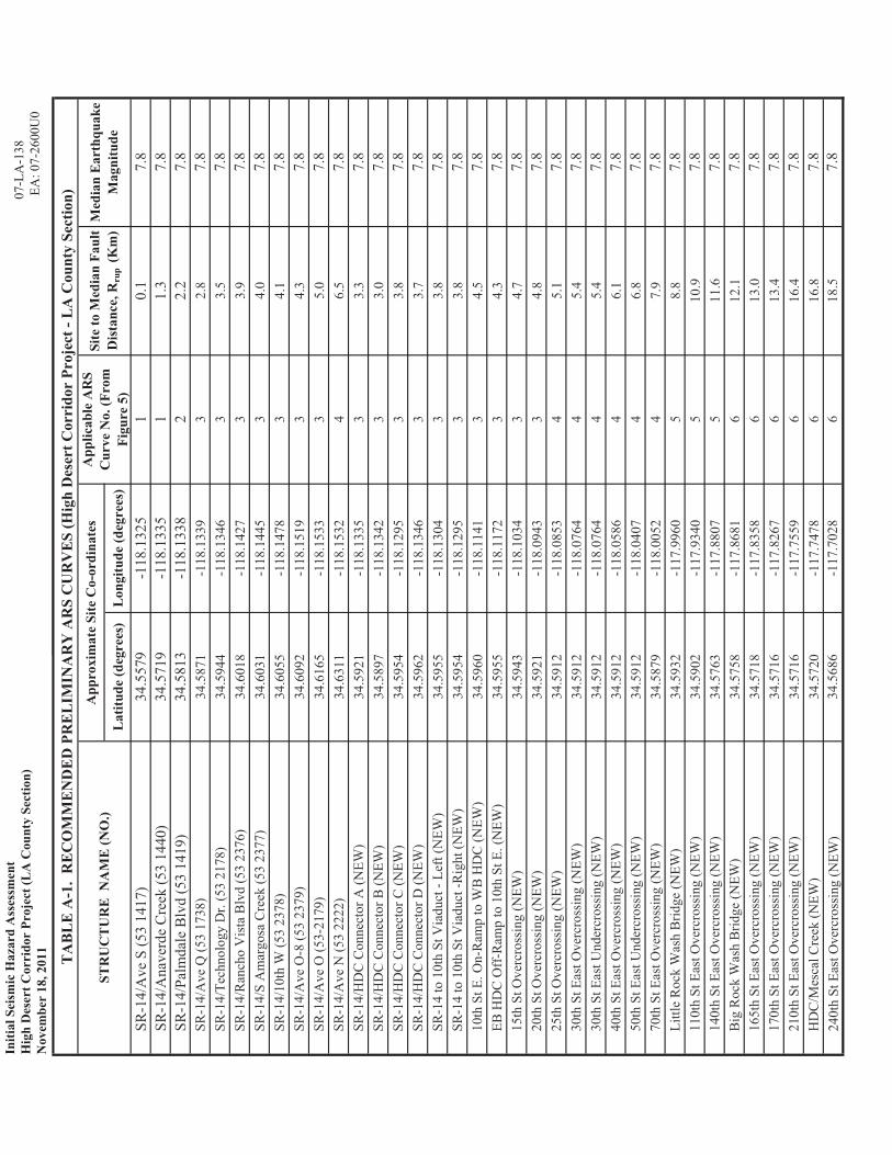
The subject project involves improvement (widening) of existing bridges along a portion of SR-14 and construction of several new bridges along the new SR-138 alignment. The subject bridge structure sites, including their approximate coordinates in terms of latitude and longitude, are listed in Table A-1 attached in Appendix A of this report. The attached Figure 2 shows the locations of a few select bridge sites.
This report presents results of our generalized preliminary seismic hazard evaluation for subject bridge sites. Findings and recommendations presented herein are based on a review of the available existing subsurface information for the existing bridge structures and published geotechnical, geologic and seismic reports. This report is prepared to aid in the planning and preliminary evaluations of the proposed bridge sites. No subsurface investigation was performed as part of this evaluation.
Updated reports including detailed site-specific evaluation of the potential seismic hazards at the each bridge site will need to be prepared for design once the results of site-specific subsurface investigations and the conceptual or preliminary design plans for the proposed improvements are available.
2.0 SUBSURFACE CONDITIONS
As part of this evaluation, we collected and reviewed the available as-built Logs of Test Borings (LOTB) for the existing bridge structures that are included in the scope of this project.
Based on our analysis, the subsurface soils at the bridge sites are anticipated to consist of mainly medium dense to dense sand within the upper 100 feet (30 m). Furthermore, for majority of the site, groundwater is not generally anticipated to be encountered within the depths that could have any significant effect on the seismic hazards. Some bridge sites are traversed by creeks. Water flows through these creeks only seasonally and for short durations. At other times, the creeks are generally dry. The presence of shallow groundwater during these wet periods may affect the seismic response of subsurface loose to medium dense predominantly cohesionless soils, if present. Site-specific evaluation is necessary to further evaluate such hazards, if any, at these bridge sites.

Initial Seismic Hazard Assessment Report 07-LA-138 High Desert Corridor Project (LA County Section) EA: 07-2600U0 November 18, 2011
Page -3-
For the purpose of this preliminary seismic hazard analysis, it is assumed the potential effects of groundwater if any would be insignificant.
Our analysis of the available subsurface data indicated that the proposed bridge sites are likely to be underlain by soils deposits with an average shear wave velocity for the upper 100 feet (30 m) or VS30 ranging mainly from 300 to 400 m/s.
3.0 FAULTING AND SEISMICITY
The subject existing bridge structures are located on a segment of SR-14 extending south from the Ave N OC (Br. No. 53-2222) to the Ave S OC (Br. No. 53-1427). The new SR-138, Los Angeles section, extends about 30 miles east from its intersection with SR-14 just north of the SR-14/Palmdale Avenue intersection to the border of the counties of Los Angeles and San Bernardino. The project area is located within a seismically active region of the Mojave Desert Geologic Province of Southern California, and just off the northern boundary of the seismically very active Central Transverse Ranges Geologic Province.
Faulting in the immediate surrounding areas is dominated by strike slip and thrust motions. The locations of the nearby major faults, as per the California Geologic Survey (CGS, 2011) with respect to the project area are shown in the attached Figure 3. As seen from this figure, the San Andreas Fault is the nearest active fault to the project alignment. The adjacent Transverse Ranges Geologic Province is underlain by a number of relatively highly active major faults.
Detailed fault parameters including the fault name, fault type, slip rate and moment magnitude of the Maximum Earthquake (Mmax) associated with the nearby major faults as per Caltrans 2007 fault database with 2009 Errata (CALTRAN, 2011) are presented in Table 1, Faulting and Seismicity, below. This fault database is used in the Caltrans’s current seismic hazard evaluation of bridge structures (CALTRANS, 2011). The slip rates presented in Table 1 are based on the 2008 California Fault Database published by the California Geologic Survey and the United States Geological Survey (CGS/USGS, 2011). As can be seen from Figure 3, the San Andreas Fault (Mojave Section) is the nearest major seismic source to the project area.
4.0 PRIMARY SEISMIC HAZARDS
The primary seismic hazards at a project site include ground motions or seismic shaking and surface fault rupture.
4.1 Design Ground Motions
A ground motion hazard analysis was performed for all the bridge sites in accordance with the Caltrans 2009 Ground Motion Determination Procedure (Caltrans, 2011), and the USGS 2008 Ground Motion Deaggregation (USGS, 2011) procedure. For this preliminary analysis, an average VS30 of 300 m/sec was used for all the bridge sites.

Initial Seismic Hazard Assessment Report 07-LA-138 High Desert Corridor Project (LA County Section) EA: 07-2600U0 November 18, 2011
Page -4-
TABLE 1. FAULTING AND SEISMICITY PARAMETERS
Fault Name Fault Type1 Slip Rate2
(mm/year)
Maximum Earthquake Moment Magnitude (Mmax) 1
San Andreas Fault (Mojave Section)
Right Lateral Strike Slip (RLSS)
29.07.0 7.8
Helendale Fault RLSS 0.60.4 7.3 Northridge Blind Thrust Reverse (R) 1.50.1 7.3
San Gabriel Fault RLSS 1.00.5 7.2
Sierra-Madre Fault Zones R 2.01.0 6.8-7.2
Simi-Santa Rosa Fault Zones
Left Lateral Strike Slip (LLSS)
1.00.5 7.0
Santa Susana Fault R 5.07.0 6.7
Clear Water Fault R N/A 6.8 Notes: (1) Based on Caltrans 2007 Fault Database, (2) Based on CGS/USGS 2008 Fault Database.
Based on the above analysis, probabilistic ground motion corresponding to the Department’s current design return period of 1,000 years (i.e., 10% probability of exceedance in 100 years) govern the design ground motion expressed in term of Acceleration Response Spectrum (ARS) for a single degree of freedom system. A set of six (6) ARS curves, developed based on the above analysis and presented in Figure 4 in Appendix A, are recommended for the initial/preliminary evaluation and/or design of the proposed bridge structures. The site coordinates, the applicable recommended ARS Curve, the approximate median site-to-fault distance (Rmode) and the median earthquake magnitude (Mmode) for each bridge site are also presented in Table A-1.
It may be noted that the Rmode and Mmode for all the project sites correspond to the distances and the Maximum Magnitude (Mmax) of the Mohave Section of the San Andreas Fault.
4.2 Fault Rupture Hazard
The SR-14/S Ave bridge site is located within a mapped A-P earthquake Fault Zone (CGS, 2011c) as shown in Figure 5. This Earthquake Fault Zone is associated with the San Andreas Fault (Mojave Section). At this time this site should be considered susceptible to fault rupture hazard. Based on preliminary estimate using the empirical procedure developed by Wells and Coppersmith (1994), the median maximum and average horizontal ground surface displacements at this bridge due to an earthquake of Mmax =7.8 associated with the nearby Mojave Section of the San Andreas Fault may be taken as 30 feet (10 m) and 16.5 feet (5 m), respectively.
The above estimated median horizontal ground rupture displacement of 30 feet may be used for the initial/preliminary planning/evaluation and/or design of the SR-14/S Ave bridge structure. Additional study, including possibly a site-specific field fault rupture hazard evaluation by a

Initial Seismic Hazard Assessment Report 07-LA-138 High Desert Corridor Project (LA County Section) EA: 07-2600U0 November 18, 2011
Page -5-
specialist, may be necessary to further evaluate fault rupture hazard and, if necessary, to develop mitigating design recommendations. The project development team, including the project structure designers and Project Manager, need to discuss this issue and decide on a further course of action as soon as possible.
The other bridge sites listed in Table A-1 are not considered susceptible to ground surface rupture or displacement hazard due fault movements.
4.3 Secondary Seismic Hazards
The secondary seismic hazards at a project site include soil liquefaction during earthquake, slope instability or landslides/movements, and seismically-induced ground and structure settlements, lateral spreading of mildly sloped grounds, and, for site near large water bodies, flooding due to earthquake motion induced seiches and tsunamis.
In the absence of groundwater within the shallow depths, the majority of the project sites are not likely to be susceptible to soil liquefaction hazards. However, near surface soils at the bridge sites that are intersected by active creek may be susceptible to soil liquefaction hazard during wet seasons. Site-specific subsurface investigation and analysis is required to further evaluate the liquefaction hazards at these sites.
Based on the location, the project area is not considered susceptible to tsunami hazard.
Based on the available information and, for preliminary design, the potential for any significant effects at the project sites due to the other secondary seismic hazards may be considered low to very low. Prepared by:
THANG LE, P.E. MOHAMMED ISLAM, Ph.D. G.E. PMP Senior Materials and Research Engineer Senior Transportation Engineer Office of Geotechnical Support Office of Geotechnical Design – South 1 Geotechnical Services Geotechnical Services California Dept of Transportation California Dept of Transportation
Attachments:
Appendix A Tables and Figures

Initial Seismic Recommendation Report 07-LA-138 High Desert Corridor Project (LA County Section) EA: 07-2600U0 November 18, 2011
REFERENCES CALTRANS (2009), Seismic Design Criteria, Version 1.6, California Department of Transportation, Sacramento California. CALTRANS (2011), ARS Online (v1.0.4), http://dap3.dot.ca.gov/shake_stable/, Accessed in November 2011, California Department of Transportation, Sacramento, California.
USGS (2011), 2008 Interactive Deaggregation (Beta), https://geohazards.usgs.gov/deaggint/2008,), Accessed in November 2011 at United Stated Geological Survey (USGS), Denver, Colorado. CGS (2011a), 2010 Fault Activity Map of California, California Geological Survey, Geologic Data Map No. 6, Compilation and Interpretation by: Charles W. Jennings and William A. Bryant, Graphics by: Milind Patel, Ellen Sander, Jim Thompson, Barbara Wanish and Milton Fonseca CGS (2011b), 2008 California Fault Parameters, Accessed in October 2011 at http://www.consrv.ca.gov/CGS/rghm/psha/index.htm, California Geological Survey Sacramento, California. CGS (2011c), Fault-Rupture Hazard Zones in California, Special Publication No. 42, California Geological Survey (previously California Divisions of Mines and Geology), Sacramento, California. CGS, (2011d), Seismic Hazard Evaluation of the Palmdale 7.5-Minute Quadrangle, Los Angeles County, California, California Geological Survey Sacramento, California. Wells, R , and Coppersmith, K. (1994), New Empirical Relationships among Magnitude, Rupture Length, Rupture Width, Rupture Area, and Surface Displacement, Bulletin of the Seismological Society of America, Vol. 84, No. 4, pp. 974-1002.
Initial Seismic Recommendation Report 07-LA-138 High Desert Corridor Project (LA County Section) EA: 07-2600U0 November 18, 2011
APPENDIX A
TABLES AND FIGURES

Palmdale
Project Area
Figure 1. High Desert Corridor Project Vicinity Map
Initial Preliminary Seismic Design Recommendations 07-LA-138High Desert Corridor Project (LA County Section) EA: 07-2600U0
Initial Seismic Hazard AssessmentHigh Desert Corridor Project (LA County Section)November 18, 2011

Figure 2. Approximate Locations of Select Bridge Sites
Bridge Sites
Initial Preliminary Seismic Design Recommendations 07-LA-138High Desert Corridor Project (LA County Section) EA: 07-2600U0
Initial Seismic Hazard AssessmentHigh Desert Corridor Project (LA County Section)November 18, 2011

LL
AN
O F
AU
LT
PRO
JEC
T A
RE
A
SAN
AN
DR
EA
S FA
UL
T
GA
RL
OC
KFA
UL
T
MIR
AG
E V
AL
LE
Y F
AU
LT
BL
AK
E R
AN
CH
FA
UL
T
SAN
GA
BR
IEL
FA
UL
T
CL
EA
R W
AT
ER
FA
UL
T
SAN
FER
NA
ND
INO
FAU
LT
SAN
TA
SU
SAN
A F
AU
LT
Figu
re 3
. N
earb
y M
ajor
Fau
lts w
ith R
efer
ence
to th
e Pr
ojec
t Are
a
Ref
eren
ce: 2
010
Faul
t Act
ivity
Map
of C
alifo
rnia
, Cal
iforn
ia G
eolo
gica
l Sur
vey,
Geo
logi
c D
ata
Map
No.
6, C
ompi
latio
n an
d In
terp
reta
tion
by: C
harle
s W
. Jen
ning
s and
Will
iam
A. B
ryan
t, G
raph
ics b
y: M
ilind
Pat
el, E
llen
Sand
er, J
im T
hom
pson
, Bar
bara
Wan
ish
and
Milt
on F
onse
ca.
Initi
al S
eism
ic H
azar
d A
sses
smen
t
07
-LA
-138
H
igh
Des
ert C
orrid
or P
roje
ct (L
A C
ount
y Se
ctio
n)
EA: 0
7-26
00U
0 N
ovem
ber 1
8, 2
011
Lat
itude
(deg
rees
)L
ongi
tude
(deg
rees
)
SR-1
4/A
ve S
(53
1417
)34
.557
9-1
18.1
325
10.
17.
8SR
-14/
Ana
verd
e C
reek
(53
1440
)34
.571
9-1
18.1
335
11.
37.
8SR
-14/
Palm
dale
Blv
d (5
3 14
19)
34.5
813
-118
.133
82
2.2
7.8
SR-1
4/A
ve Q
(53
1738
)34
.587
1-1
18.1
339
32.
87.
8SR
-14/
Tech
nolo
gy D
r. (5
3 21
78)
34.5
944
-118
.134
63
3.5
7.8
SR-1
4/R
anch
o V
ista
Blv
d (5
3 23
76)
34.6
018
-118
.142
73
3.9
7.8
SR-1
4/S
Am
argo
sa C
reek
(53
2377
)34
.603
1-1
18.1
445
34.
07.
8SR
-14/
10th
W (5
3 23
78)
34.6
055
-118
.147
83
4.1
7.8
SR-1
4/A
ve O
-8 (5
3 23
79)
34.6
092
-118
.151
93
4.3
7.8
SR-1
4/A
ve O
(53-
2179
)34
.616
5-1
18.1
533
35.
07.
8SR
-14/
Ave
N (5
3 22
22)
34.6
311
-118
.153
24
6.5
7.8
SR-1
4/H
DC
Con
nect
or A
(NEW
)34
.592
1-1
18.1
335
33.
37.
8SR
-14/
HD
C C
onne
ctor
B (N
EW)
34.5
897
-118
.134
23
3.0
7.8
SR-1
4/H
DC
Con
nect
or C
(NEW
)34
.595
4-1
18.1
295
33.
87.
8SR
-14/
HD
C C
onne
ctor
D (N
EW)
34.5
962
-118
.134
63
3.7
7.8
SR-1
4 to
10t
h St
Via
duct
- Le
ft (N
EW)
34.5
955
-118
.130
43
3.8
7.8
SR-1
4 to
10t
h St
Via
duct
-Rig
ht (N
EW)
34.5
954
-118
.129
53
3.8
7.8
10th
St E
. On-
Ram
p to
WB
HD
C (N
EW)
34.5
960
-118
.114
13
4.5
7.8
EB H
DC
Off
-Ram
p to
10t
h St
E. (
NEW
)34
.595
5-1
18.1
172
34.
37.
815
th S
t Ove
rcro
ssin
g (N
EW)
34.5
943
-118
.103
43
4.7
7.8
20th
St O
verc
ross
ing
(NEW
)34
.592
1-1
18.0
943
34.
87.
825
th S
t Ove
rcro
ssin
g (N
EW)
34.5
912
-118
.085
34
5.1
7.8
30th
St E
ast O
verc
ross
ing
(NEW
)34
.591
2-1
18.0
764
45.
47.
830
th S
t Eas
t Und
ercr
ossi
ng (N
EW)
34.5
912
-118
.076
44
5.4
7.8
40th
St E
ast O
verc
ross
ing
(NEW
)34
.591
2-1
18.0
586
46.
17.
850
th S
t Eas
t Und
ercr
ossi
ng (N
EW)
34.5
912
-118
.040
74
6.8
7.8
70th
St E
ast O
verc
ross
ing
(NEW
)34
.587
9-1
18.0
052
47.
97.
8Li
ttle
Roc
k W
ash
Brid
ge (N
EW)
34.5
932
-117
.996
05
8.8
7.8
110t
h St
Eas
t Ove
rcro
ssin
g (N
EW)
34.5
902
-117
.934
05
10.9
7.8
140t
h St
Eas
t Ove
rcro
ssin
g (N
EW)
34.5
763
-117
.880
75
11.6
7.8
Big
Roc
k W
ash
Brid
ge (N
EW)
34.5
758
-117
.868
16
12.1
7.8
165t
h St
Eas
t Ove
rcro
ssin
g (N
EW)
34.5
718
-117
.835
86
13.0
7.8
170t
h St
Eas
t Ove
rcro
ssin
g (N
EW)
34.5
716
-117
.826
76
13.4
7.8
210t
h St
Eas
t Ove
rcro
ssin
g (N
EW)
34.5
716
-117
.755
96
16.4
7.8
HD
C/M
esca
l Cre
ek (N
EW)
34.5
720
-117
.747
86
16.8
7.8
240t
h St
Eas
t Ove
rcro
ssin
g (N
EW)
34.5
686
-117
.702
86
18.5
7.8
TA
BL
E A
-1.
RE
CO
MM
EN
DE
D P
RE
LIM
INA
RY
AR
S C
UR
VE
S (H
igh
Des
ert C
orri
dor
Proj
ect -
LA
Cou
nty
Sect
ion)
App
roxi
mat
e Si
te C
o-or
dina
tes
App
licab
le A
RS
Cur
ve N
o. (F
rom
Fi
gure
5)
Site
to M
edia
n Fa
ult
Dis
tanc
e, R
rup
(Km
)M
edia
n E
arth
quak
e M
agni
tude
STR
UC
TU
RE
NA
ME
(NO
.)
Initi
alPr
elim
inar
ySe
ism
icD
esig
nR
ecom
men
datio
ns07
-LA
-138
Hig
hD
eser
tCor
ridor
Proj
ect(
LAC
ount
ySe
ctio
n)EA
:07-
2600
U0
Initi
alSe
ism
icH
azar
dA
sses
smen
tH
igh
Des
ertC
orri
dor
Proj
ect(
LA
Cou
nty
Sect
ion)
Nov
embe
r18
,201
1

3 2.5g)
ARS
CURV
E N
O. 1
ARS
CURV
EN
O2
2celeration (
ARS
CURV
E N
O. 2
ARS
CURV
E N
O. 3
1.5pectral Acc
ARS
CURV
E N
O. 4
ARS
CURV
E N
O. 5 A
RSCU
RVE
NO
6
0.51S
ARS
CURV
E N
O. 6
0 0.0
0.5
1.0
1.5
2.0
2.5
3.0
3.5
4.0
4.5
5.0
Per
iod
(se
c)
Fig
ure
..
.
Rec
omm
end
ed
Pre
lim
inar
y A
RS
Cu
rves
4
Initi
alPr
elim
inar
ySe
ism
icD
esig
nR
ecom
men
datio
ns07
-LA
-138
Hig
hD
eser
tCor
ridor
Proj
ect(
LAC
ount
ySe
ctio
n)EA
:07-
2600
U0
Initi
alSe
ism
icH
azar
dA
sses
smen
tH
igh
Des
ertC
orrid
orPr
ojec
t(LA
Cou
nty
Sect
ion)
Nov
embe
r18,
2011

SSAANN AANNDDRREEAASS FFAAUULLTT ZZOONNEE SR -14/S Ave Bridge
SR-14/Anaverde Cr Br
SR-14/Palmdale Ave
A-P Earthquake Fault Zones
Figure 5. Nearest 3 Bridge Locations in Relation to the A-P Earthquake Fault Zones
Initial Preliminary Seismic Design Recommendations 07-LA-138High Desert Corridor Project (LA County Section) EA: 07-2600U0
Initial Seismic Hazard AssessmentHigh Desert Corridor Project (LA Section)November 18, 2011