hdr 24 hdr 24/96 quick start guidec3.zzounds.com/media/mac_hdr2496_qs-bc19c490e1df...7. impress your...
TRANSCRIPT

QUICK START GUIDEHDR 24HDR 24HDR 24HDR 24HDR 24/96
24 TRACK/24 BIT, DIGITAL AUDIO HARD DISK RECORDER AND EDITOR
2 HDR 24/96
HD
R 2
4/
96
1. Read instuctions — Read, understand and follow all safety and operatinginstructions before using the HDR24/96.
2. Retain Instructions — Keep these safety and operating instructions for futurereference.
3. Heed Warnings — Follow all warnings on the HDR24/96 and in theseoperating instructions.
4. Water and Moisture — Do not use the HDR24/96 near water – for example,near a bathtub, kitchen sink, garden hose, incontinent poodle, sweatydrummer, etc. – or when condensation has formed on the unit.
5. Heat and Ventilation — Locate the HDR24/96 away from heat sources suchas radiators, campfires, compost pits, heliarc welders, magma flows, etc. Donot block HDR24/96 ventilation openings or install in spaces that preventadequate air circulation to the unit.
6. Power Sources — Connect the HDR24/96 only to a power source of the typedescribed in these operating instructions or as marked on the HDR24/96.
7. Power Cord Protection — Route power supply cords so that they are not likelyto be walked upon, tripped over, or abraded by items placed upon or againstthem. Pay particular attention to cords at plugs, convenience receptacles, andthe point where they exit the HDR24/96.
8. Object and Liquid Entry — Do not drop objects or spill liquids into theHDR24/96. Clean only with a damp cloth; do not clean with liquid or aerosolcleaners.
9. Attachments — Use the HDR24/96 with only the accessories specified in thismanual.
10. Damage Requiring Service — The HDR24/96 should be serviced only byqualified service personnel when:
A. The power supply cord or the plug has been damaged; or
B. Objects have fallen onto, or liquid has spilled into the unit; or
C. The unit has been exposed to rain or water; or
D. The unit does not appear to operate normally or exhibits a marked change in performance; or
E. The unit has been dropped, or its chassis damaged.
11. Servicing — Do not attempt to service the HDR24/96. All servicingshould be referred to the Mackie Service Department.
12. Lightning — Unplug the HDR 24/96 during lightning storms or whenunused for long periods of time.
13. Grounding and Polarization — To prevent electric shock, do not use theHDR24/96 polarized plug with an extension cord, receptacle or otheroutlet unless the blades can be fully inserted to prevent blade exposure.Do not defeat the HDR24/96 grounding by plugging into an ungroundedreceptacle or ground lift adapter.
This apparatus does not exceed the Class A/Class B (whichever is applicable)limits for radio noise emissions from digital apparatus as set out in the radiointerference regulations of the Canadian Department of Communications.
ATTENTION — Le présent appareil numérique n’émet pas de bruitsradioélectriques dépassant las limites applicables aux appareils numériques declass A/de class B (selon le cas) prescrites dans le réglement sur le brouillageradioélectrique édicté par les ministere des communications du Canada.
This product has been tested and complies with thefollowing standards and directives as set forth by theEuropean Union:
* EN 55022 Radiated and Conducted Emissions
* EN 61000-4-2 Electrostatic Discharge Immunity
* EN 61000-4-3 RF Electromagnetic Fields Immunity
* EN 61000-4-4 Electrical Fast Transient/Burst Immunity
* EN 60950/IEC 950 Electrical Safety Requirements
FCC Information
NOTE: This equipment has been tested and found to complywith the limits for a Class A digital devices, pursuant to Part 15of the FCC Rules. These limits are designed to providereasonable protection against harmful interference when theequipment is operated in a commercial installation. Thisequipment generates, uses, and can radiate radio frequencyenergy and, if not installed and used in accordance with theinstruction manual, may cause harmful interference to radiocommunications. Operation of this equipment in a residentialarea is likely to cause harmful interference in which case theuser will be required to correct the interference at his ownexpense.
CAUTION AVISRISK OF ELECTRIC SHOCK
DO NOT OPENRISQUE DE CHOC ELECTRIQUE
NE PAS OUVRIR
CAUTION: TO REDUCE THE RISK OF ELECTRIC SHOCKDO NOT REMOVE COVER (OR BACK)
NO USER-SERVICEABLE PARTS INSIDEREFER SERVICING TO QUALIFIED PERSONNEL
ATTENTION: POUR EVITER LES RISQUES DE CHOCELECTRIQUE, NE PAS ENLEVER LE COUVERCLE. AUCUN
ENTRETIEN DE PIECES INTERIEURES PAR L’USAGER. CONFIERL’ENTRETIEN AU PERSONNEL QUALIFIE.
AVIS: POUR EVITER LES RISQUES D’INCENDIE OUD’ELECTROCUTION, N’EXPOSEZ PAS CET ARTICLE
A LA PLUIE OU A L’HUMIDITE
The lightning flash with arrowhead symbol within an equilateral triangle is intended to alert the user to the presence of uninsulated"dangerous voltage" within the product’s enclosure, that may be of sufficient magnitude to constitute a risk of electric shock to persons.
Le symbole clair avec point de fl che l’int rieur d’un triangle quilat ral est utilis pour alerter l’utilisateur de la pr sence
l’int rieur du coffret de "voltage dangereux" non isol d’ampleur suffisante pour constituer un risque d’ l ctrocution.
The exclamation point within an equilateral triangle is intended to alert the user of the presence of important operating and maintenance (servicing) instructions in the literature accompanying the appliance.
Le point d’exclamation l’int rieur d’un triangle quilat ral est employ pour alerter les utilisateurs de la pr sence d’instructions importantes pour le fonctionnement et l’entretien (service) dans le livret d’instruction accompagnant l’appareil.
Important Safety Instructions
WARNING — Before applying power to the HDR24/96, make sure that theVoltage Selector switch next to the AC inlet jack on the rear panel is setto the line voltage used in your region. Powering-on the HDR24/96with the Voltage Selector switch set incorrectly will cause an electricaland fire hazard that may result in irreparable damage to the unit.
WARNING — To reduce the risk of fire or electric shock, do not expose thisappliance to rain or moisture.
3Quick Start Guide
Qu
ick S
tart G
uid
e
®
Please write your serial number here for futurereference:
Purchased at:
Date Of Purchase:
ContentsIntroduction ----------------------------4
Conventions ---------------------------------- 5About “Tape” --------------------------------- 5Overview -------------------------------------- 6
Setup & Configuration----------------7Required Equipment ------------------------ 7Installation------------------------------------ 7
I/O Cards & Cables ------------------------------- 8Sync Card & Cable - Word Clock and DigitalSynchronization ---------------------------------- 10Mackie Media (Optional) ----------------------- 12Monitor / Mouse / Keyboard (Optional) --- 13Remote 24 / Remote 48 Pro (Optional) ----- 14Footswitch (Optional) --------------------------- 14
Power-Up -------------------------------------- 14Configuration--------------------------------- 15
I/O Cards ------------------------------------------- 15Synchronization ---------------------------------- 19
Hookups ----------------------------------------20Analog Hookup (AIO•8) ------------------------- 20TDIF Hookup (DIO•8) ---------------------------- 22ADAT Optical Hookup (DIO•8 or OPT•8) ---- 24AES/EBU Hookup (PDI•8) ----------------------- 27
HDR24/96 Operation-----------------29Opening Projects ---------------------------- 29Basic Transport Operations ----------------30Time Displays --------------------------------- 31Locate Points and Looping----------------- 32Cues -------------------------------------------- 34Creating Projects ---------------------------- 36Naming Tracks-------------------------------- 38Monitoring ------------------------------------ 38Metering and Setting Levels -------------- 40Recording ------------------------------------- 42Autopunch ------------------------------------ 44Footswitch Operation ---------------------- 45Delete Last ------------------------------------ 46Saving Projects --------------------------------46Project Backup / Restore ------------------ 47
Appendix A: Compatible Cables ----50Analog and Digital Multitrack Cables ----50Other Cables---------------------------------- 51
Troubleshooting and Service--------54
Manual Part No. 820-225-00 Rev. B 11/00© 2000 Mackie Designs Inc., All rights reservedPrinted in the U.S.A.

4 HDR 24/96
HD
R 2
4/
96 Introduction
Save your Box!Uncle Jeff’s Bottom Ten Reasons to Save the Box:
10. You think boxes grow on trees?
9. It’s actually a time capsule, packed with a biological code that can’t bedecrypted until 2043.
8. Its festive graphics will cheer up those other boxes forgotten in yourattic.
7. Impress your friends: tape it up and pretend that you actually have twoHDR24/96s.
6. If you throw it away, bad people will know you have a studio in yourhouse.
5. Someday, when paper costs more than steel, it could net you a fortune.
4. The HDR24/96 itself only costs $47.95. The balance is what you paid forthe box.
3. Properly sealed, it can be used as a flotation device in the unlikely eventof a water landing.
2. It’s a great place to hide your old digital 8-track recorder.
1. If you collect ten HDR24/96 boxes, Greg will come over for dinner (thisoffer does not apply to dealers or distributors).
In the unlikely event that you should need to send the HDR24/96 back to Mackiefor service, please use the shipping box it came in. This box has been speciallydesigned to minimize damage to the HDR24/96 during shipping, so that it won’tend up more broken than when you sent it.
How To Use This GuideWelcome to the cutting edge of affordable multitrack recording and editing! Weknow you’re feeling eager, but please take a few minutes and read this brief QuickStart Guide before you jump into your first HDR24/96 session. The first part ofthis guide explains how to install and configure the various HDR24/96 I/O cardsand connect the HDR24/96 to an analog or digital console. The second partdescribes how to start a session, operate the basic transport and monitoringcontrols, and explains the terms and conventions used to name, store, and retrieveprojects on disk.
To get the most out of this guide, you’ll need to be familiar with the basicmultitrack recording process. To take advantage of the built-in Graphical UserInterface (GUI), you’ll need to attach a standard SVGA computer monitor, mouse,and keyboard. This Quick Start Guide covers both front panel and GUI operation.
We have purposely excluded all the extra stuff from this guide to give you just thebasic information you need to get going right away. For step-by-step tutorials, in-depth feature descriptions, and endless technical details, see the Applications andReference Manuals on the companion CD-ROM. Updated manuals and the latestsoftware releases can be obtained via Mackie’s website at: www.mackie.com.

5Quick Start Guide
Qu
ick S
tart G
uid
e
ConventionsThe HDR24/96 Quick Start Guide uses the following conventions to help you findinformation quickly:
Text Conventionsa) Keyboard Keys (example: SHIFT )b) Keyboard keys you hold at same time (example: CTRL+SHIFT+6)c) File or folder names (example: C:\HDR Projects\Ode To Masters\Ode
To Masters.hdr)d) Software or hardware controls (example: Punch)e) Proper names of objects in GUI or front/rear panel (example: Transport)
IconsThis icon identifies a description of how to perform an action with the mouse.
This icon identifies a description of how to perform an action with the keyboard.
This icon identifies a description of how to perform an action from the front panel.
This icon identifies in-depth explanations of features and practical tips. Thoughnot required reading, they do offer some choice tidbits of knowledge that willleave you wiser for the reading.
This icon identifies information that is critically important to the operation of theHDR24/96. So for your own sake, please read these sections.
About “Tape”No, you’re not reading the wrong manual. Our goal was to build a hard diskrecorder that is comfortable for someone familiar with tape recording, but thatdoesn’t require you to get a brain transplant from a computer geek to use. Whenfamiliar terms such as Tape Inputs, Tape Returns, Transport, and the like areapplied to the HDR24/96, they mean exactly what you expect them to mean.Where the well-worn shoe fits, we continue to wear it.

6 HDR 24/96
HD
R 2
4/
96 Overview
By combining traditional multitrack tape recording features with the power andflexibility of graphical non-linear editing, the Mackie Designs HDR24/96 takesmultitrack recording to a level never before achieved by a product in its pricerange. In addition to the standard battery of traditional tape-based features, theHDR24/96:
• Combines the familiarity of a multitrack tape machine with the security ofnon-destructive recording and non-degrading recording media.
• Includes a Graphical User Interface and a built-in DAW-style editor,accessible by adding an SVGA monitor, two-button PS/2 compatiblemouse, and a standard PC keyboard.
• Can record simultaneously on all 24 tracks. At either 44.1 kHz or 48 kHzsample rate, the internal hard drive will store over 2100 track-minutes of24-bit audio. That’s 90 minutes of 24 full tracks, six reels worth at 30inches per second!
• Has eight Virtual Takes per track, allowing you to record multiple passeswithout having to change routing and bussing assignments or useadditional tracks.
• Can interface with any analog or digital console. The HDR24/96 uses thesame I/O cards as the Mackie Digital 8•Bus console: the AIO•8 (24-bitanalog A/D and D/A), DIO•8 (TDIF/ADAT Optical), PDI•8 (AES/EBU), andlow-cost OPT•8 (ADAT Optical).
• Provides three convenient methods of backup: Mackie Media M•90, aremovable hard drive (also capable of 24-track recording and playback),Mackie Media PROJECT, a removable drive using inexpensive, removable2.2 GB ORB cartridges; and data transfer to another computer through theHDR24/96’s 100 Base-T Ethernet port via the built-in FTP server.
• Offers two optional remote control devices – the compact Remote 24 forsmaller project studios, and the full-featured Remote 48 Pro for controllingup to 48 tracks with full Auto-Locater and Jog/Shuttle Wheel.
REWIND FAST FWD PLAYSTOP RECORD
SELECTSELECTSELECTSELECT
ON
POWER LOC 2LOC 1 STORELOOP1–2
RECSAFE
AUTOTAKE
T-CODECHASE TRACKDELETE LAST PROJECT BACKUP DISK UTIL SYSTEM DIGI-I/O SYNC DEC INCAUTO
INPUTALL
INPUT
242322212019181716151413121110987654321
242322212019181716151413121110987654321
HDR 24/ 24TRACK/24BIT DIGITAL AUDIO HARD DISK RECORDER/EDITOR HIGH RESOLUTION AUDIO 44.1/48/96K SAMPLE RATES
REC REC REC REC REC REC REC REC REC REC REC REC REC REC REC REC REC REC REC REC REC REC REC REC
96
MINUTESHOURS SECONDS FRAMES
TICKSBEATSBARS
44.1k
VARI
48k
24 BIT
ERROR
96k
16 BIT
TC CLOCK
OL
24
7
10152025
303540
50
OL
24
7
10152025
303540
50
OL
24
7
10152025
303540
50
OL
24
7
10152025
303540
50
OL
24
7
10152025
303540
50
OL
24
7
10152025
303540
50
OL
24
7
10152025
303540
50
OL
24
7
10152025
303540
50
OL
24
7
10152025
303540
50
OL
24
7
10152025
303540
50
OL
24
7
10152025
303540
50
OL
24
7
10152025
303540
50
OL
24
7
10152025
303540
50
OL
24
7
10152025
303540
50
OL
24
7
10152025
303540
50
OL
24
7
10152025
303540
50
OL
24
7
10152025
303540
50
OL
24
7
10152025
303540
50
OL
24
7
10152025
303540
50
OL
24
7
10152025
303540
50
OL
24
7
10152025
303540
50
OL
24
7
10152025
303540
50
OL
24
7
10152025
303540
50
PROJECT: Little love PLAYLIST: Playlist 1 DRIVE: C:Internal AVAIL: 01:35:00
Media Tray Floppy Drive
Monitoring &Record Safe
Locate &Loop Auto Take &
Time codeChase
TransportLCD Control
System Control
Status Display CurrentTime Display
LCD DisplayMeter DisplayRecord Ready

7Quick Start Guide
Qu
ick S
tart G
uid
e
Setup & ConfigurationThis chapter explains how to set up and configure the HDR24/96 for use in yourstudio. Two application examples show how to interface the HDR24/96 withanalog and digital recording consoles.
Required EquipmentOf course, there’s more to a studio than a recorder and some musicians. At aminimum, you’ll need the following to make the HDR24/96 feel at home:
• 3 Mackie 8-channel I/O (input/output) cards.
• A console with a minimum of 24 tape sends (busses or direct outputs) andreturns (line inputs or monitor returns). If your analog console has only 8tape sends, use Y-cord splitters to send tape out 1 to HDR24/96 Inputs 1,9 and 17; tape out 2 to HDR24/96 Inputs 2, 10, and 18, and so forth.
• Cables to connect the HDR24/96 to the console: 3 or 6 multi-channelsnakes or fiber optic cables, depending on your I/O setup.
• All the stuff that typically connects to a console: microphones,instruments, outboard equipment, control room monitors, and so on.
• Optional, but strongly recommended: an SVGA monitor, two-button PS/2mouse, and PC keyboard for the Graphical User Interface.
InstallationThis section describes how to install the I/O cards and how to connect theHDR24/96 to your console. Before you begin, you should choose a location foryour HDR24/96 considering the following:
• If you’re not using the GUI interface, Remote 24, or Remote 48 Pro,position the front panel within convenient reach of your normal recording/mixing position. If you are using the GUI interface, you might want to getthe HDR24/96 out of the way. Be aware that although analog and AES/EBU cables can be fairly long, TDIF Optical and Remote 24/Remote 48Pro cables are limited to about 10 meters. ADAT Optical and KVM(keyboard, video, mouse) cables can reach up to about 15 meters.
• The HDR24/96 requires a reliable AC power source with a good ground.Do not use a ground lift adapter or plug the HDR24/96 into anungrounded receptacle. Remember, this is a computer. Using anuninterruptible power supply (UPS) to power the HDR24/96 is a good ideato avoid an unexpected shutdown and protect it from transient linevoltages.
Warning!Before applying power to the HDR24/96, make sure that the Voltage Selectorswitch next to the AC inlet jack on the rear panel is set to the line voltage usedin your region. Powering-on the HDR24/96 with the Voltage Selector switchset incorrectly will cause an electrical and fire hazard that may result inirreparable damage to the unit.
8 HDR 24/96
HD
R 2
4/
96 I/O Cards & Cables
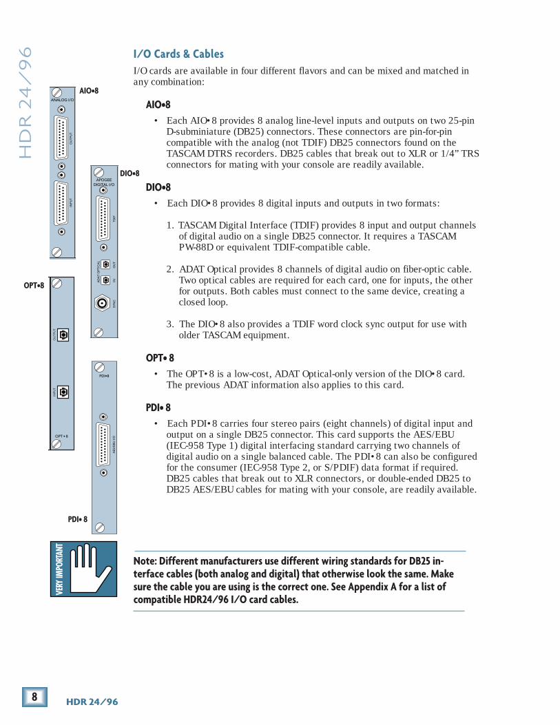
I/O cards are available in four different flavors and can be mixed and matched inany combination:
AIO•8• Each AIO•8 provides 8 analog line-level inputs and outputs on two 25-pin
D-subminiature (DB25) connectors. These connectors are pin-for-pincompatible with the analog (not TDIF) DB25 connectors found on theTASCAM DTRS recorders. DB25 cables that break out to XLR or 1/4” TRSconnectors for mating with your console are readily available.
DIO•8• Each DIO•8 provides 8 digital inputs and outputs in two formats:
1. TASCAM Digital Interface (TDIF) provides 8 input and output channelsof digital audio on a single DB25 connector. It requires a TASCAMPW-88D or equivalent TDIF-compatible cable.
2. ADAT Optical provides 8 channels of digital audio on fiber-optic cable.Two optical cables are required for each card, one for inputs, the otherfor outputs. Both cables must connect to the same device, creating aclosed loop.
3. The DIO•8 also provides a TDIF word clock sync output for use witholder TASCAM equipment.
OPT• 8• The OPT•8 is a low-cost, ADAT Optical-only version of the DIO•8 card.
The previous ADAT information also applies to this card.
PDI• 8• Each PDI•8 carries four stereo pairs (eight channels) of digital input and
output on a single DB25 connector. This card supports the AES/EBU(IEC-958 Type 1) digital interfacing standard carrying two channels ofdigital audio on a single balanced cable. The PDI•8 can also be configuredfor the consumer (IEC-958 Type 2, or S/PDIF) data format if required.DB25 cables that break out to XLR connectors, or double-ended DB25 toDB25 AES/EBU cables for mating with your console, are readily available.
APOGEEDIGITAL I/O
SYN
CIN
OU
TTD
IF
AD
AT
OPT
ICA
L
INPU
TO
UTP
UT
ANALOG I/O
AIO•8
DIO•8
PDI•8
AE
S/E
BU
I/O
PDI• 8
OPT•8
Note: Different manufacturers use different wiring standards for DB25 in-terface cables (both analog and digital) that otherwise look the same. Makesure the cable you are using is the correct one. See Appendix A for a list ofcompatible HDR24/96 I/O card cables.

9Quick Start Guide
Qu
ick S
tart G
uid
eTo install the I/O cards:
1. If the HDR24/96 is plugged into AC power, unplug it.
2. Remove the I/O card slot cover plates by removing the rather tight topand bottom screws with a screwdriver.
3. Before you take I/O cards from their bags, touch a grounded metal objectto discharge any static electricity from your body.
4. Remove the I/O card from its bag and hold it so that the component sidefaces left.
5. Line up the card so that the top and bottomedges slide smoothly into the white cardguides. Push the card all the way in until itsfaceplate is flush with the back panel.
6. Hand-tighten the thumbscrews at the topand bottom of the card. Do not use ascrewdriver.
Note:Note:Note:Note:Note: Always hand tighten the thumbscrewsat the top and bottom of all I/O cards be-fore operating the HDR 24/96.
If you want to hook up the HDR24/96 I/O cablesto your console right now, see the console hookupdiagrams in Hookups (page 20). Be sure to comeright back here when you’re done.
10 HDR 24/96
HD
R 2
4/
96 Sync Card & Cable - Word Clock and Digital Synchronization
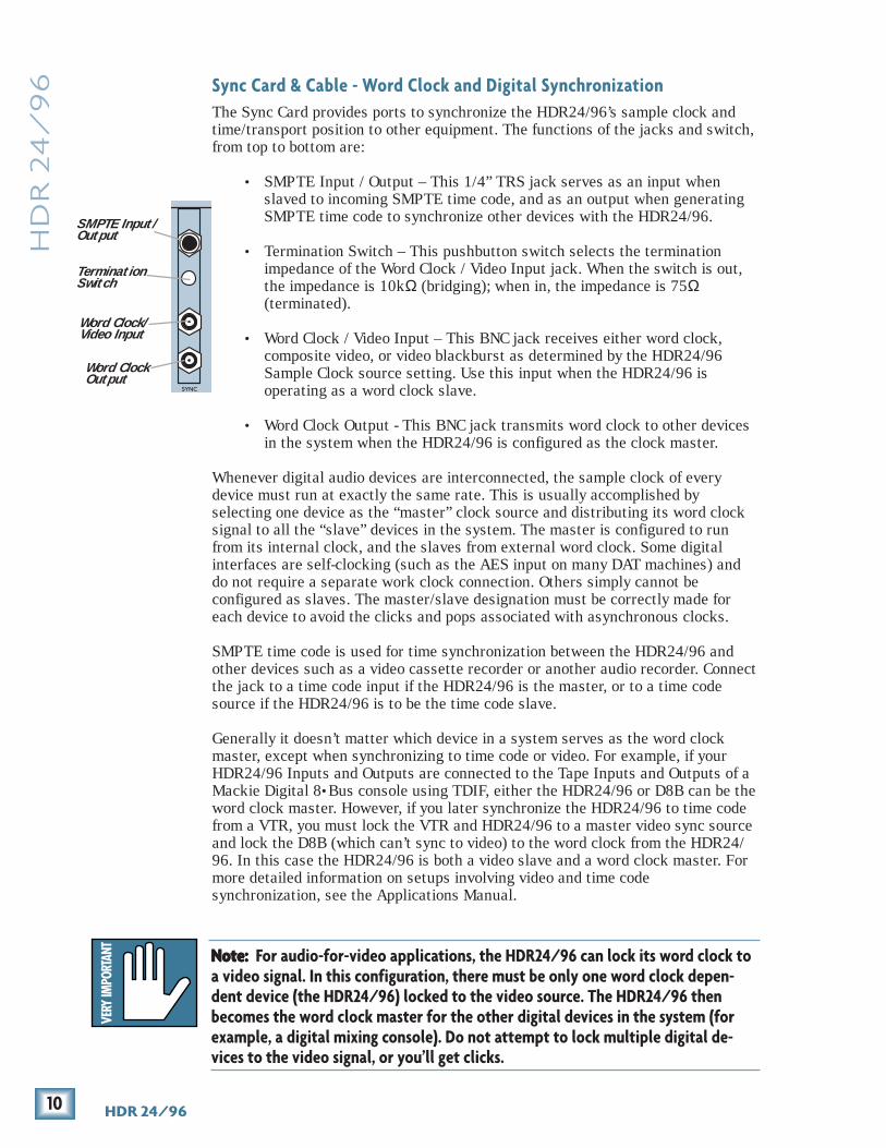
The Sync Card provides ports to synchronize the HDR24/96’s sample clock andtime/transport position to other equipment. The functions of the jacks and switch,from top to bottom are:
• SMPTE Input / Output – This 1/4” TRS jack serves as an input whenslaved to incoming SMPTE time code, and as an output when generatingSMPTE time code to synchronize other devices with the HDR24/96.
• Termination Switch – This pushbutton switch selects the terminationimpedance of the Word Clock / Video Input jack. When the switch is out,the impedance is 10kΩ (bridging); when in, the impedance is 75Ω(terminated).
• Word Clock / Video Input – This BNC jack receives either word clock,composite video, or video blackburst as determined by the HDR24/96Sample Clock source setting. Use this input when the HDR24/96 isoperating as a word clock slave.
• Word Clock Output - This BNC jack transmits word clock to other devicesin the system when the HDR24/96 is configured as the clock master.
Whenever digital audio devices are interconnected, the sample clock of everydevice must run at exactly the same rate. This is usually accomplished byselecting one device as the “master” clock source and distributing its word clocksignal to all the “slave” devices in the system. The master is configured to runfrom its internal clock, and the slaves from external word clock. Some digitalinterfaces are self-clocking (such as the AES input on many DAT machines) anddo not require a separate work clock connection. Others simply cannot beconfigured as slaves. The master/slave designation must be correctly made foreach device to avoid the clicks and pops associated with asynchronous clocks.
SMPTE time code is used for time synchronization between the HDR24/96 andother devices such as a video cassette recorder or another audio recorder. Connectthe jack to a time code input if the HDR24/96 is the master, or to a time codesource if the HDR24/96 is to be the time code slave.
Generally it doesn’t matter which device in a system serves as the word clockmaster, except when synchronizing to time code or video. For example, if yourHDR24/96 Inputs and Outputs are connected to the Tape Inputs and Outputs of aMackie Digital 8•Bus console using TDIF, either the HDR24/96 or D8B can be theword clock master. However, if you later synchronize the HDR24/96 to time codefrom a VTR, you must lock the VTR and HDR24/96 to a master video sync sourceand lock the D8B (which can’t sync to video) to the word clock from the HDR24/96. In this case the HDR24/96 is both a video slave and a word clock master. Formore detailed information on setups involving video and time codesynchronization, see the Applications Manual.
SYNC
SMPTE Input/Output
TerminationSwitch
Word Clock/Video Input
Word ClockOutput
Note: Note: Note: Note: Note: For audio-for-video applications, the HDR24/96 can lock its word clock toa video signal. In this configuration, there must be only one word clock depen-dent device (the HDR24/96) locked to the video source. The HDR24/96 thenbecomes the word clock master for the other digital devices in the system (forexample, a digital mixing console). Do not attempt to lock multiple digital de-vices to the video signal, or you’ll get clicks.

11Quick Start Guide
Qu
ick S
tart G
uid
eThe following are recommended setups for establishing proper sample clocksynchronization with the devices connected to the HDR24/96 digital I/O cards.
TDIF (DIO•8)With the HDR24/96 as a master, connect Word Clock Out of the HDR24/96 toWord Clock In on the receiving device(s). If connecting to older TASCAMDTRS recorders, use the Sync Out port on the first DIO•8 card instead ofWord Clock Out. If there is more than one DTRS recorder in the chain,connect Sync Out to the word clock input of the first DTRS recorder only; theother recorders are synchronized through their interconnecting DTRS cables.
With the HDR24/96 operating as a slave to another TDIF device, connect theword clock output from the master TDIF device to Word Clock In on theHDR24/96.
ADAT Optical (DIO•8, OPT•8)With the HDR24/96 as a master, set the receiving device(s) to derive sampleclock from their ADAT Optical ports if the ports are self-clocking. In thiscase, no word clock connection is necessary. If the ADAT Optical ports on thereceiving devices are not self-clocking, connect Word Clock Out of theHDR24/96 to Word Clock In on the receiving device(s).
With the HDR24/96 configured as a slave, connect the word clock out of themaster ADAT Optical device to Word Clock In on the HDR24/96.
AES/EBU (PDI•8)With the HDR24/96 as a master, set the receiving device(s) to derive theirsample clock from the AES/EBU ports if the ports are self-clocking. In thisinstance, no word clock connection is necessary. If the AES/EBU ports on thereceiving device(s) are not self-clocking, connect Word Clock Out of theHDR24/96 to Word Clock In of the receiving device(s).
With the HDR24/96 as a slave, connect the word clock out of the masterAES/EBU device to Word Clock In on the HDR24/96.
SYNC
TerminationSwitch
Word clockinput jack
BNC-Teeadaptor
Word Clock toother Slaves
Word ClockFrom Master
Note:Note:Note:Note:Note: Use 75 Ω coaxial cables when con-necting word clock or video to the SyncCard Word Clock/Video input jack. If theHDR24/96 is at the end of a cable that’sconnected to several devices, push theTermination Switch in; otherwise leave itout and use a BNC Tee adapter to feed thesignal on to the next device in the chain.
Note:Note:Note:Note:Note: If you are using an HDR24/96 with the Mackie Digital8•Bus console, you may need to turn on the Digital 8•Bus first.The Clock I/O on the D8B prefers not to see an active signal atits Word Clock input when it powers up.

12 HDR 24/96
HD
R 2
4/
96 Mackie Media (Optional)
The HDR24/96 emulates the tape library tradition with Mackie Media M•90 andMackie Media PROJECT drives. Both drives come complete with a plug-in tray forquick removal and a nifty storage case for shelving and transporting the drives.Trays can be purchased separately if you want to use your own UDMA IDE drives.The HDR24/96 can record or play directly off the M•90 so you can change sessionsas quickly as changing tape on a 24-track – no backup time required. PROJECTdrives are for backup only and use removable 2.2GB ORB cartridges that fit in yourpocket. Each can hold a couple of 5-minute 24-track masters.
To install or remove a Mackie Media tray:
1. Power the HDR24/96 off whenever inserting or removing media trays.If you have an active project, don’t forget to save it first!
2. To remove a drive, first unlock it by inserting the key and turning it aquarter-turn counterclockwise. Two keys are packed with the recorder, andone with each M•90 drive.
3. Lift the bail handle to release the drive, and pull it out of the drive bay.
4. To install a new M•90 or PROJECT drive, slide the media tray into thefront panel drive bay. Press it firmly into place, and latch it by pressing thebail handle downward until it’s fully seated.
5. Insert the key into the lock and turn it a quarter-turn clockwise. The keylocks the drive into place and powers the tray.
6. The HDR24/96 will automatically detect the Mackie Media drive when younext power it up.
Note: Note: Note: Note: Note: Mackie Media are hard drives, and as we all know, hard drivesinvolve some pretty intricate technology. So don’t shake the littledarlin’, and if a tray has just come in from a freezing car or airplanecargo hold, do not install it until it has reached room temperature.
Mackie Media Tray
Mackie MediaReceiver REWIND FAST FWD PLAYSTOP RECORD
SELECTSELECTSELECTSELECT
ON
POWER LOC 2LOC 1 STORELOOP1–2
RECSAFE
AUTOTAKE
T-CODECHASE TRACKDELETE LAST PROJECT BACKUP DISK UTIL SYSTEM DIGI-I/O SYNC DEC INCAUTO
INPUTALL
INPUT
242322212019181716151413121110987654321
242322212019181716151413121110987654321
HDR 24/ 24TRACK/24BIT DIGITAL AUDIO HARD DISK RECORDER/EDITOR HIGH RESOLUTION AUDIO 44.1/48/96K SAMPLE RATES
REC REC REC REC REC REC REC REC REC REC REC REC REC REC REC REC REC REC REC REC REC REC REC REC
96
MINUTESHOURS SECONDS FRAMES
TICKSBEATSBARS
44.1k
VARI
48k
24 BIT
ERROR
96k
16 BIT
TC CLOCK
OL
24
710152025
30354050
OL
24
710152025
30354050
OL
24
710152025
30354050
OL
24
710152025
30354050
OL
24
710152025
30354050
OL
24
710152025
30354050
OL
24
710152025
30354050
OL
24
710152025
30354050
OL
24
710152025
30354050
OL
24
710152025
30354050
OL
24
710152025
30354050
OL
24
710152025
30354050
OL
24
710152025
30354050
OL
24
710152025
30354050
OL
24
710152025
30354050
OL
24
710152025
30354050
OL
24
710152025
30354050
OL
24
710152025
30354050
OL
24
710152025
30354050
OL
24
710152025
30354050
OL
24
710152025
30354050
OL
24
710152025
30354050
OL
24
710152025
30354050
PROJECT: Little love PLAYLIST: Playlist 1 DRIVE: C:Internal AVAIL: 01:35:00
13Quick Start Guide
Qu
ick S
tart G
uid
e
Video
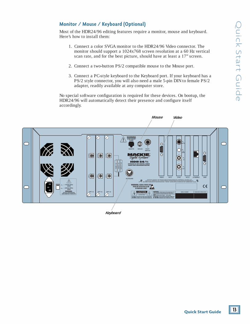
Monitor / Mouse / Keyboard (Optional)Most of the HDR24/96 editing features require a monitor, mouse and keyboard.Here’s how to install them:
1. Connect a color SVGA monitor to the HDR24/96 Video connector. Themonitor should support a 1024x768 screen resolution at a 60 Hz verticalscan rate, and for the best picture, should have at least a 17” screen.
2. Connect a two-button PS/2 compatible mouse to the Mouse port.
3. Connect a PC-style keyboard to the Keyboard port. If your keyboard has aPS/2 style connector, you will also need a male 5-pin DIN to female PS/2adapter, readily available at any computer store.
No special software configuration is required for these devices. On bootup, theHDR24/96 will automatically detect their presence and configure itselfaccordingly.
Keyboard
Mouse

14 HDR 24/96
HD
R 2
4/
96
FOOT SWTO HDR
REMOTE JACKREMOTE 24
DO NOT PLUG INTOETHERNET
WARNING
Note:Note:Note:Note:Note: If you are using an HDR24/96 with the Mackie Digital 8•Bus console,you may need to turn on the Digital 8•Bus first. The Clock I/O on the D8Bprefers not to see an active signal at its Word Clock input when it powers up.
Note:Note:Note:Note:Note: The Remotesduplicate nearly allof the front paneloperating controls.When we describe afront panel opera-tion, you’ll probablyfind it available onthe Remote also. Ifyou have a Remote,try it both ways. Ifyou don’t have aRemote yet, think ofhow convenient itwould be.
Remoteconnection
Footswitch
Ethernet Jack
Back panel of theMackie Remote 24
Note:Note:Note:Note:Note: The HDR24/96 ‘REMOTE’ andEthernet jacks both accept CAT-5 Ethernetcables - don’t get them mixed up!
Footswitch
Remote 24 / Remote 48 Pro (Optional)Installing either Remote is as simple as plugging in a telephone. Connect one endof the cable (supplied with the Remote) to the ‘REMOTE’ jack on HDR24/96 rearpanel, and the other end to the ‘TO HDR REMOTE JACK’ jack on the Remote. It’sOK to plug or unplug either Remote with the HDR24/96 powered on.
Footswitch (Optional)For hands-free do-it-yourself punches and other frequently-used functions likePlay/Stop, New Cue, Take Select, and Next Cue, connect the cable of a momentary,normally open footswitch to the ‘FOOT SWITCH’ 1/4" TS jack on the rear panel ofthe HDR24/96, the Remote 24, or Remote 48 Pro. If you have a Remote installedyou can connect two foot switches, one to the HDR24/96 and one to the Remote.Each footswitch functions independently of the other. Footswitch functionality isassigned in the front panel System menu or the GUI General Setup window. Seethe Reference Manual for more details.
Power-UpOK, NOW you can turn it on. Assuming you have already connected the HDR24/96to your console, power up the HDR24/96 first, then the outboard equipment andconsole, and finally the power amplifiers or powered monitors. Audio equipmenttends to generate unexpected clicks and pops when you power it up, so bypowering up your monitoring system last, you’ll save your speakers and your ears.
Before you read the next section, take a quick, self-guided tour of the front paneldisplay and controls to get a sense of where they are.

15Quick Start Guide
Qu
ick S
tart G
uid
e
DIGI-I/O
ConfigurationBefore starting a Project, you will need to configure the HDR24/96 I/O cardoptions and synchronization parameters. These parameters determine where thesample clock is coming from, how fast the sample clock runs, and how many bitsare recorded in every sample. Some options, like sample rate and bit depth, willbecome “standards” that you won’t need to change very often. The remainingsynchronization options (for time code and video) are covered in detail in theApplications and Reference Manuals.
I/O CardsOnly the DIO•8 and PDI•8 cards require special configuration. If you are usingAIO•8 or OPT•8 cards only, you can skip to the next section.
DIO•8 CardTo set the DIO•8 input and output formats:
1. Press Digi I/O to enterthe Digital I/O Card Setupscreen.
2. Select In.
The Setup Tape Inputs screen showsyou the current input settings foreach of the three I/O cards.
3. Press the Select buttoncorresponding to each DIO•8 cardand toggle the selection between ADAT and TDIF.
4. Press the Page Left (<) button to return to the previous screen.
5. Now select Out.
The Setup Tape Outputs screenshows you the current outputsettings for each of the three I/Ocards.
6. For each DIO•8 card present,press the Select button to select the desired output format. Or, selectthe TD–>AD or AD–>TD option to convert between formats, bypassingthe HDR24/96 tape signal path entirely.
7. When done, press Digi I/O to exit the menu.
(SETUP TAPE INPUTS) 1-8 9-16 17-24 ADAT ADAT ADAT
(SETUP TAPE OUTPUTS) 1-8 9-16 17-24 ADAT ADAT ADAT
Note:Note:Note:Note:Note: The front paneldisplay’s backlightswitches off afterseveral minutes of in-activity. It’ll comeback on automati-cally when it’s neededto display new infor-mation, but you canrevive it at any timeby pressing either thePage LeftPage LeftPage LeftPage LeftPage Left [<<<<<] or PagePagePagePagePage
RightRightRightRightRight [>>>>>] buttonbelow the display.
DIGITAL I/O Card Setup Stat Rate In Out Bits Convert

16 HDR 24/96
HD
R 2
4/
96 1. Select Setup from the Windows menu (or use keyboard
shortcut CTRL+1) and click on the Digital I/O icon.
The Digital I/O Setup dialog shows you the current settingsfor each of the three I/O cards (see illustration below).
2. Click on the Input pulldown menu and select eitherADAT or TDIF for each DIO•8 card.
3. Click on the Output pulldown menu and select thedesired output format. Or, select the TDIF–>ADAT orADAT–>TDIF option to convert between formats,bypassing the HDR24/96 tape signal path entirely.
4. Click the arrow in the top right corner of the dialog or hit ESC to exit.
I/O Card 1-8(AIO•8)
I/O Card 9-16(DIO•8)
I/O Card 17-24 (PDI•8)
24- bit Analog
ADAT
ADAT
Apogee DIO AES-EBU
Setup
ADATTDIFTD -> ADAD -> TD
The input and output settings on the DIO•8 card need not be the same.For example, you can use outboard A/D converters with ADAT Opticaloutputs and a console with TDIF inputs without problems. Just rememberto correctly set up Word Clock.
17Quick Start Guide
Qu
ick S
tart G
uid
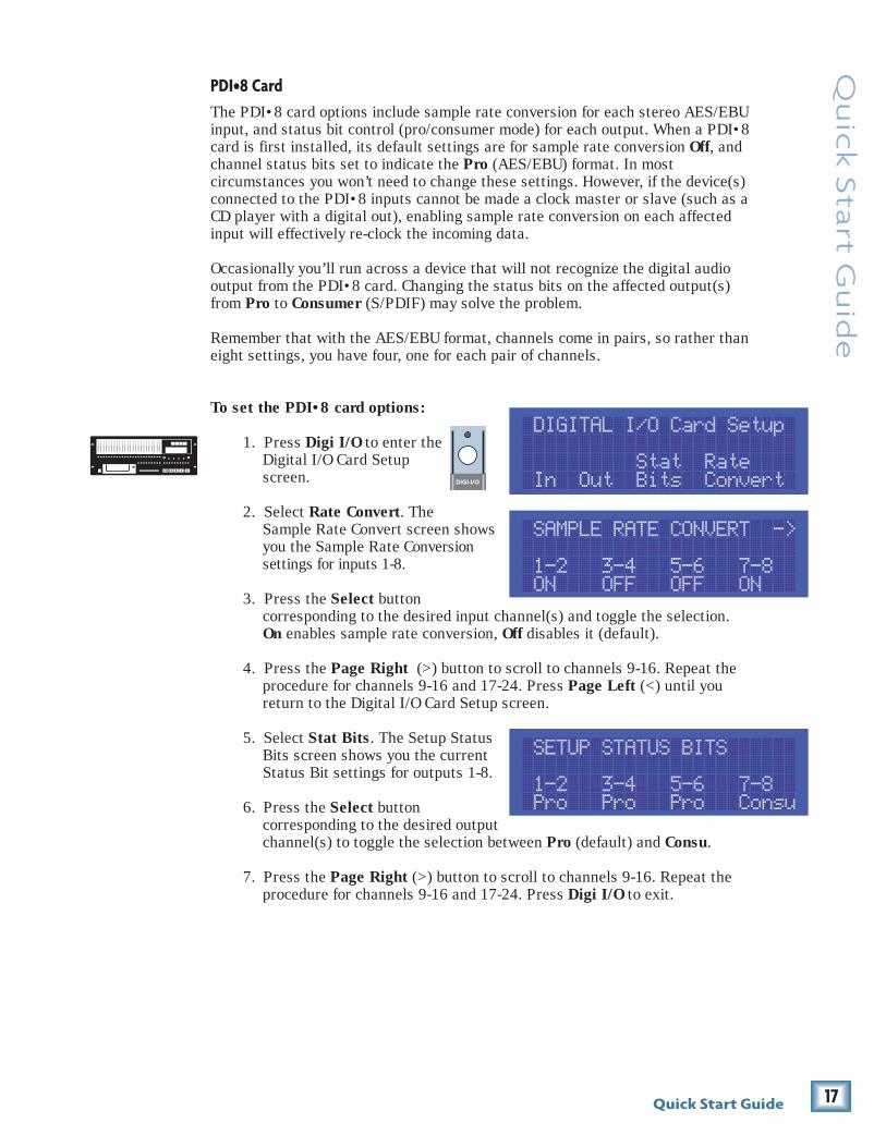
ePDI•8 CardThe PDI•8 card options include sample rate conversion for each stereo AES/EBUinput, and status bit control (pro/consumer mode) for each output. When a PDI•8card is first installed, its default settings are for sample rate conversion Off, andchannel status bits set to indicate the Pro (AES/EBU) format. In mostcircumstances you won’t need to change these settings. However, if the device(s)connected to the PDI•8 inputs cannot be made a clock master or slave (such as aCD player with a digital out), enabling sample rate conversion on each affectedinput will effectively re-clock the incoming data.
Occasionally you’ll run across a device that will not recognize the digital audiooutput from the PDI•8 card. Changing the status bits on the affected output(s)from Pro to Consumer (S/PDIF) may solve the problem.
Remember that with the AES/EBU format, channels come in pairs, so rather thaneight settings, you have four, one for each pair of channels.
To set the PDI•8 card options:
1. Press Digi I/O to enter theDigital I/O Card Setupscreen.
2. Select Rate Convert. TheSample Rate Convert screen showsyou the Sample Rate Conversionsettings for inputs 1-8.
3. Press the Select buttoncorresponding to the desired input channel(s) and toggle the selection.On enables sample rate conversion, Off disables it (default).
4. Press the Page Right (>) button to scroll to channels 9-16. Repeat theprocedure for channels 9-16 and 17-24. Press Page Left (<) until youreturn to the Digital I/O Card Setup screen.
5. Select Stat Bits. The Setup StatusBits screen shows you the currentStatus Bit settings for outputs 1-8.
6. Press the Select buttoncorresponding to the desired outputchannel(s) to toggle the selection between Pro (default) and Consu.
7. Press the Page Right (>) button to scroll to channels 9-16. Repeat theprocedure for channels 9-16 and 17-24. Press Digi I/O to exit.
DIGI-I/O
DIGITAL I/O Card Setup Stat Rate In Out Bits Convert
SAMPLE RATE CONVERT -> 1-2 3-4 5-6 7-8 ON OFF OFF ON
SETUP STATUS BITS 1-2 3-4 5-6 7-8 Pro Pro Pro Consu

18 HDR 24/96
HD
R 2
4/
96
I/O Card 17-24
24- bit Analog
ADAT
ADAT
Apogee DIO AES-EBU
Setup
Setup AES Card - Slot 3
Pro
Pro
Stadus Bits:
Pro
Pro
ConsumerPro
Sample Rate Conversion:
1- 2 Converted
3- 4 Converted
5- 6 Converted
7- 8 Converted
Optimal settings are - NOT converted and Pro.
1. Select Setup from the Windows menu (or use keyboardshortcut CTRL+1).
2. Click on the Digital I/O icon. For each PDI•8 card, clickthe Setup button. In the AES/EBU Setup dialog, checkthe Converted boxes corresponding to the desiredinput(s) to enable sample rate conversion; leave theboxes unchecked for no sample rate conversion(default).
3. Then select Pro (default) or Consumer from thepulldown menus associated with the desired output(s).Click the arrow in the top right corner of the dialog orhit ESC to exit.
Note: Note: Note: Note: Note: When sample rate conversion is active, the input signal is truncated to 20bits, causing a slight degradation in the signal quality of a 24-bit input. Thereforesample rate conversion should be enabled only when intentionally converting asignal to a different sample rate (e.g. from 44.1k to 48k), or when no other meansexist to establish clock synchronization with the device(s). See the ReferenceManual for details.

19Quick Start Guide
Qu
ick S
tart G
uid
e
SYNC
SYNC OPTIONS -> Sample Time Code Clock Rate Source Rate
SynchronizationSample Clock SourceThe Sample Clock setting determines the source of the HDR24/96 sample clock. Ifthe HDR24/96 is a clock master or not connected to any other digital device(s),set it to Internal. If the HDR24/96 is a word clock slave, set it to Word Clock. Athird option is Video and this is discussed in the Reference Manual.
Sample RateThe Sample Rate determines how fast the HDR24/96 sample clock runs. CompactDisks use a 44.1 kHz sample rate; the video production folks prefer 48 kHzbecause their digital video recorders use 48 kHz.
Bit-DepthThe Bit Depth setting determines how many bits are contained in each audiosample recorded to disk (the bit “resolution”). While 16-Bit audio takes up 1/3less disk space than 24-Bit audio, 24-Bit audio offers the potential for greaterdynamic range (the difference between the softest and loudest sounds that can berecorded) and captures a more accurate “image” of the sound.
To configure the HDR24/96 Synchronization settings:1. Press Sync to enter the Sync
Options menu. Select SampleClock. Using the – Dec / + Incor << / >> buttons, select eitherInternal or Word Clockaccording to your setup. We’ll leave video sync for the Reference Manual.
2. Select OK to return to the Sync Options menu.
3. Select Sample Rate. Using the – Dec / + Inc buttons or << / >> buttons,set the Sample Rate to 44.1 kHz or 48 kHz. Select OK.
4. Move to the next page of the SyncOptions menu with the Page Right (>)button.
5. Select Bit Depth. Using the – Dec / +Inc or << / >> buttons, set the Bit Depth to 16 Bit or 24 Bit. Select OK,then press the Sync button to exit the menu.
1. Select Setup fromthe Windows menu(or use keyboardshortcut CTRL+1)and click on theSync icon.
2. Select the desiredsettings from theSample Clock, BitDepth, and Sample Rate pulldown menus.
3. Click the arrow in the top right corner of the dialog or hit ESC to exit.
You must still selectthe HDR24/96’s
Sample Rate even if it’sslaved to another
device’s clock. If youdon’t set it correctly,the HDR24/96 time
display will run at thewrong rate, even
though audio will playat the right speed.
<- SYNC OPTIONS -> Bit Generate TC Depth SMPTE MTC Offset

20 HDR 24/96
HD
R 2
4/
96 Hookups
This section shows how the HDR24/96 is typically connected to either analog ordigital consoles (using the Mackie Analog and Digital 8•Bus consoles asexamples). These examples assume that the rest of your studio equipment(monitors, sound sources, outboard processing, etc.) is already connected, or thatyou know how to connect it.
Before you begin, note how the three eight-channel I/O cards are arranged on theHDR24/96 rear panel: 1-8 is on the left, 9-16 is in the center, and 17-24 is on theright. Labeling cables before you begin will make connecting the HDR24/96 toyour console easier.
The specific hookups for each HDR24/96 I/O card are shown below.
Analog Hookup (AIO•8)This example describes the hookup for the 24•8 analog console.
Cables & Hardware(3) AIO•8 cards for HDR(6) Analog snakes, DB25 to eight 1/4” TRS phone plugs
Hookup1. Connect three snakes to the HDR24/96 Inputs (bottom connector). If you
want to have the ability to route any console input to any recorder track,then connect the 1/4” plugs on each of the three snakes to the like-numbered Submaster / Tape Output jacks on the 8•Bus console. Thisworks as long as you don’t record more than 8-channels at a time, sincethe Submaster Outputs 9-16 and 17-24 are the same as outputs 1-8.
Alternately, you can connect the console’s direct outputs to the recorder’sinputs, so that each console channel feeds the like-numbered recordertrack. Or, you can use a combination of direct and subgroup outs. Thehookup diagram below shows the HDR24/96 inputs connected to theSubmaster Outputs. See the Applications Manual for additional tips.
Note:Note:Note:Note:Note: If you are us-ing a D8B console
with either DIO•8,PDI•8, or OPT•8
cards installed,then a Clock I/O
card must also beinstalled in the D8B
to properly syn-chronize its word
clock with theHDR24/96.
24•8 SUBMASTER / TAPE OUTPUTS
HDR24/96 AIO Cards
HDR24/96 back panel
8 7
15
6
14
5
13
4
12
3
11
2
10
1
9
TAPE RETURNS 1-8
15 13 11 9
7 5 3 1
16 14 12 10
6 4 28
17
18
19
20
21
22
23
24
16
TAPE RETURNS 9-16
TAPE RETURNS 17-24
171820 1921222324
TAPE IN/OUTS
INPU
TO
UTP
UT
INPU
TO
UTP
UT
INPU
TO
UTP
UT
ANALOG I/O ANALOG I/O ANALOG I/O
120VAC 50/60 Hz 475W
VIDEO SYNCACC 1 ACC 2 ETHERNET MIDI
1-8 9-16 17-24
TAPE IN/OUTS
INPU
TO
UTP
UT
INPU
TO
UTP
UT
INPU
TO
UTP
UT
ANALOG I/O ANALOG I/O ANALOG I/O
21Quick Start Guide
Qu
ick S
tart G
uid
e
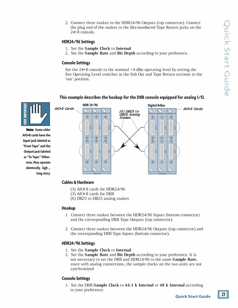
This example describes the hookup for the D8B console equipped for analog I/O.
TAPE IN/OUTS
INPU
TO
UTP
UT
INPU
TO
UTP
UT
INPU
TO
UTP
UT
ANALOG I/O ANALOG I/O ANALOG I/O
TAPE IN/OUTS
INPU
TO
UTP
UT
INPU
TO
UTP
UT
INPU
TO
UTP
UT
ANALOG I/O ANALOG I/O ANALOG I/O(6) DB25 toDB25 AnalogSnakes
Digital 8•BusHDR 24/96AIO•8 CardsAIO•8 Cards
Cables & Hardware(3) AIO•8 cards for HDR24/96(3) AIO•8 cards for D8B(6) DB25 to DB25 analog snakes
Hookup1. Connect three snakes between the HDR24/96 Inputs (bottom connector)
and the corresponding D8B Tape Outputs (top connector).
2. Connect three snakes between the HDR24/96 Outputs (top connector) andthe corresponding D8B Tape Inputs (bottom connector).
HDR24/96 Settings1. Set the Sample Clock to Internal.2. Set the Sample Rate and Bit Depth according to your preference. It is
not necessary to set the D8B and HDR24/96 to the same Sample Rate,since with analog connections, the sample clocks on the two units are notsynchronized
Console Settings1. Set the D8B Sample Clock to 44.1 k Internal or 48 k Internal according
to your preference.
Note:Note:Note:Note:Note: Some olderAIO•8 cards have theInput jack labeled as“From Tape” and theOutput jack labeledas “To Tape.” Other-
wise, they operateidentically. Sigh ...
long story.
2. Connect three snakes to the HDR24/96 Outputs (top connector). Connectthe plug end of the snakes to the like-numbered Tape Return jacks on the24•8 console.
HDR24/96 Settings1. Set the Sample Clock to Internal.2. Set the Sample Rate and Bit Depth according to your preference.
Console SettingsSet the 24•8 console to the nominal +4 dBu operating level by setting thefive Operating Level switches in the Sub Out and Tape Return sections to the‘out’ position.
22 HDR 24/96
HD
R 2
4/
96 TDIF Hookup (DIO•8)
NoteNoteNoteNoteNote: Determiningwhich unit in Figure 1provides the master
clock depends onyour application. For
information on ad-vanced applications,see the Applications
Manual.
Cables & Hardware(3) DIO•8 cards for HDR24/96(3) DIO•8 cards for D8B(1) Clock I/O card for D8B(3) TDIF cables(1) 75 Ω BNC word clock cable
Hookup1. Connect the three TDIF cables between the corresponding TDIF jacks on
the HDR24/96 and D8B.
2. When TDIF is used, the D8B must have a Clock I/O card installed. Tomake the D8B the clock master, connect its Word Clock Out (not DIO•8Sync out) to the HDR24/96 Word Clock In. To make the HDR24/96 theclock master, connect its Word Clock Out to the D8B Word Clock In.See Figure 1.
HDR24/96 Settings1. Set the Tape Input format for each DIO•8 card to TDIF, and the Tape
Output format to TDIF.
2. If the HDR24/96 is the clock master, set the Sample Clock to Internal;if it is a clock slave, set it to Word Clock and depress the 75 Ωtermination switch on the Sync card.
3. Set the Sample Rate to 44.1 kHz or 48 kHz according to yourpreference.
Console Settings1. Set the Tape Input and Tape Output format for each DIO•8 card to TDIF.
2. If the D8B is the clock master, set the Sample Clock to either 44.1 kInternal or 48 k Internal; if it is a clock slave, set the Sample Clock toeither 44.1 kHz or 48 kHz. Set the Sample Rate to match the SampleRate selected on the HDR24/96.

23Quick Start Guide
Qu
ick S
tart G
uid
e
TDIF Hookup with DIO•8
Digital 8•Bus
APOGEESYNC
AP
OG
EE
Wor
dC
lock
Out
Wor
dC
lock
In
WordClock Out
(HDR24/96as Master)
WordClock Out
(D8B asMaster)
TDIF Connection
APOGEEDIGITAL I/O
SYN
CIN
OU
TTD
IF
AD
AT
OPT
ICA
L
APOGEEDIGITAL I/O
SYN
CIN
OU
TTD
IF
AD
AT
OPT
ICA
L
APOGEEDIGITAL I/O
SYN
CIN
OU
TTD
IF
AD
AT
OPT
ICA
L
WordClock In
TDIF Cables(DB25)
DIO•8 CardsWordClock Out
ApogeeClock I/OCard
TDIF Connection
SYNC
APOGEEDIGITAL I/O
SYN
CIN
OU
TTD
IF
AD
AT
OPT
ICA
L
APOGEEDIGITAL I/O
SYN
CIN
OU
TTD
IF
AD
AT
OPT
ICA
L
APOGEEDIGITAL I/O
SYN
CIN
OU
TTD
IF
AD
AT
OPT
ICA
L
HDRSyncCard
WordClock In
HDR 24/96
DIO•8 Cards
Figure 1
WordClock Out
Use oneonly
Depress theTerminationbutton if theHDR24/96 is setto Slave
Note:The Word Clockconnectionsshown here arethe same forFigure 2, 3 and 4

24 HDR 24/96
HD
R 2
4/
96
Note:Note:Note:Note:Note: Determiningwhich unit in
Figures 2 & 3 pro-vides master clock
depends on yourapplication. For in-
formation onadvanced applica-
tions, see theApplications
Manual.
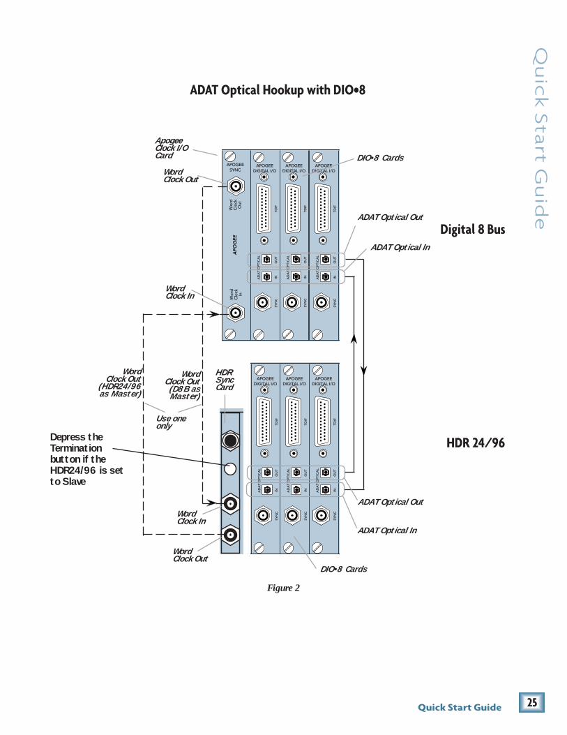
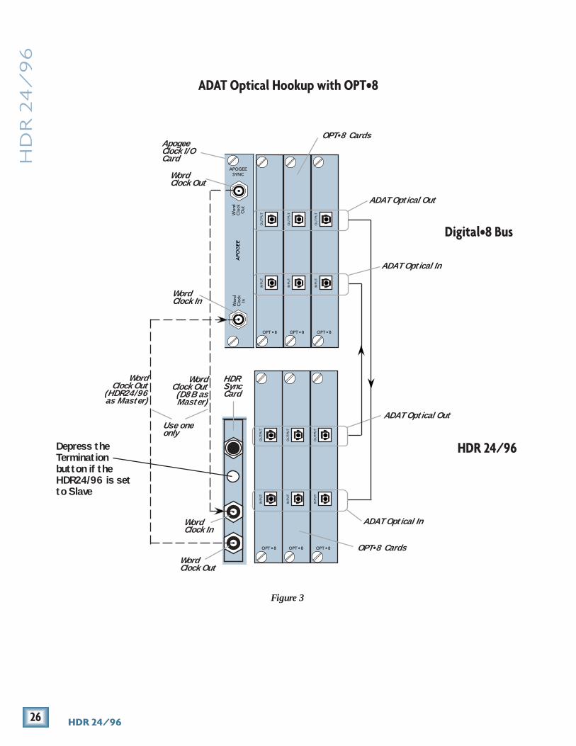
ADAT Optical Hookup (DIO•8 or OPT•8)Cables & Hardware
(3) DIO•8 or OPT•8 cards for HDR24/96(3) DIO•8 or OPT•8 cards for D8B(1) Clock I/O card for D8B(6) ADAT Optical cables(1) 75Ω BNC word clock cable
Hookup1. Connect three ADAT Optical cables from the HDR24/96 Optical Outputs to
the Optical Inputs on the corresponding D8B I/O cards.
2. Connect three ADAT Optical cables from the HDR24/96 Optical Inputs tothe Optical Outputs on the corresponding D8B I/O cards.
3. When ADAT Optical is used, the D8B must have a Clock I/O cardinstalled. To make the D8B the clock master, connect its Word Clock Outto the HDR24/96 Word Clock In. To make the HDR24/96 the clock master,connect its Word Clock Out to the D8B Word Clock In.
HDR24/96 Settings1. If you have DIO•8 cards installed, set the Tape Input and Tape Output
format for each card to ADAT. OPT•8 cards need no configuration.
2. If the HDR24/96 is the clock master, set the Sample Clock to Internal; Ifthe HDR24/96 is a clock slave, set the Sample Clock to Word Clock anddepress the 75Ω termination button on the Sync card.
3. Set the Sample Rate to 44.1 kHz or 48 kHz according to your preference.
Console Settings1. If you have DIO•8 cards installed, set the Tape Input and Tape Output
format for each card to ADAT. OPT•8 cards need no configuration.
2. If the D8B is the clock master, set the Sample Clock to either 44.1 kInternal or 48 k Internal; if it is a clock slave, then set the Sample Clockto either 44.1 kHz or 48 kHz. Set the Sample Rate to match the SampleRate selected on the HDR24/96.
25Quick Start Guide
Qu
ick S
tart G
uid
e
ADAT Optical Hookup with DIO•8
APOGEESYNC
AP
OG
EE
Wor
dC
lock
Out
Wor
dC
lock
In
ADAT Optical In
APOGEEDIGITAL I/O
SYN
CIN
OU
TTD
IF
AD
AT
OPT
ICA
L
APOGEEDIGITAL I/O
SYN
CIN
OU
TTD
IF
AD
AT
OPT
ICA
L
APOGEEDIGITAL I/O
SYN
CIN
OU
TTD
IF
AD
AT
OPT
ICA
L
ADAT Optical Out
Digital 8 Bus
DIO•8 Cards
APOGEEDIGITAL I/O
SYN
CIN
OU
TTD
IF
AD
AT
OPT
ICA
L
APOGEEDIGITAL I/O
SYN
CIN
OU
TTD
IF
AD
AT
OPT
ICA
L
APOGEEDIGITAL I/O
SYN
CIN
OU
TTD
IF
AD
AT
OPT
ICA
L
HDR 24/96
Figure 2
DIO•8 Cards
ADAT Optical In
ADAT Optical Out
Depress theTerminationbutton if theHDR24/96 is setto Slave
WordClock Out
(HDR24/96as Master)
WordClock Out
(D8B asMaster)
WordClock In
WordClock Out
ApogeeClock I/OCard
HDRSyncCard
WordClock In
WordClock Out
Use oneonly
26 HDR 24/96
HD
R 2
4/
96
ADAT Optical In
ADAT Optical Out
Digital•8 Bus
OPT•8 Cards
HDR 24/96
Figure 3
OPT•8 Cards
ADAT Optical In
ADAT Optical Out
ADAT Optical Hookup with OPT•8
APOGEESYNC
AP
OG
EE
Wor
dC
lock
Out
Wor
dC
lock
In
WordClock Out
(HDR24/96as Master)
WordClock Out
(D8B asMaster)
WordClock In
WordClock Out
ApogeeClock I/OCard
SYNC
HDRSyncCard
WordClock In
WordClock Out
Use oneonly
Depress theTerminationbutton if theHDR24/96 is setto Slave

27Quick Start Guide
Qu
ick S
tart G
uid
e
Note:Note:Note:Note:Note: Determiningwhich unit in Figure 4provides master clock
depends on yourapplication. For infor-
mation on advancedapplications, see the
Applications Manual.
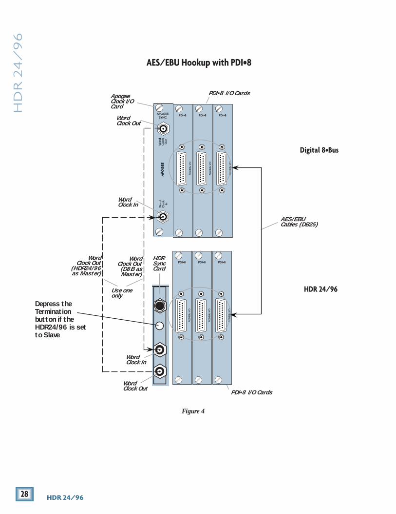
AES/EBU Hookup (PDI•8)Cables & Hardware
(3) PDI•8 cards for HDR24/96(3) PDI•8 cards for D8B(1) Clock I/O card for D8B(3) DB25 to DB25 AES/EBU snakes(1) 75Ω BNC word clock cable
Hookup1. Connect the three AES/EBU cables between the corresponding AES/EBU
connectors on the HDR24/96 and D8B.
2. When AES/EBU is used, the D8B must have a Clock I/O card installed. Tomake the D8B the clock master, connect its Word Clock Out to theHDR24/96 Word Clock In. To make the HDR24/96 the master, connect itsWord Clock Out to the D8B Word Clock In.
HDR24/96 Settings1. If the HDR24/96 is the clock master, set the Sample Clock to Internal; if
it is a clock slave, set the Sample Clock to Word Clock and depress the75Ω termination switch on the Sync card.
2. Set the Sample Rate to 44.1 kHz or 48 kHz according to your preference.
Console Settings1. If the D8B is the clock master, set the Sample Clock to either 44.1 k
Internal or 48 k Internal; if it is a clock slave, set the Sample Clock toeither 44.1 kHz or 48 kHz. Set the sample rate to match the Sample Rateselected on the HDR24/96.
OK, so we fibbed a little. You can use PDI•8 cards in the D8B without a Clock I/O card installed, but doing so requires that you enable sample rate conversionon both the D8B and the HDR24/96 in lieu of word clock synchronization.Sample rate conversion results in a 4-bit loss in sample resolution that may de-grade the quality of the sound slightly. So, the moral of the story is that unlessyou just blew your wad on a new guitar and are eating peanut butter sand-wiches until your next paycheck, go buy a Clock I/O card.
28 HDR 24/96
HD
R 2
4/
96
AES/EBU Hookup with PDI•8
PDI•8
AE
S/E
BU
I/O
AES/EBUCables (DB25)
PDI•8 I/O Cards
Digital 8•Bus
HDR 24/96
Figure 4
APOGEESYNC
AP
OG
EE
Wor
dC
lock
Out
Wor
dC
lock
In
WordClock Out
(HDR24/96as Master)
WordClock Out
(D8B asMaster)
WordClock In
WordClock Out
ApogeeClock I/OCard
SYNC
HDRSyncCard
WordClock In
WordClock Out
Use oneonly
Depress theTerminationbutton if theHDR24/96 is setto Slave
PDI•8
AE
S/E
BU
I/O
PDI•8
AE
S/E
BU
I/O
PDI•8
AE
S/E
BU
I/O
PDI•8
AE
S/E
BU
I/O
PDI•8
AE
S/E
BU
I/O
PDI•8 I/O Cards

29Quick Start Guide
Qu
ick S
tart G
uid
e
HDR24/96 OperationNow that you’ve finished installing and configuring the HDR24/96, you’re almostready to start your first Project. We still want you to read this entire guide, but wealready hear some of you shuffling and muttering. Okay, okay, okay... for theterminally impatient, read this chapter, then you can go out and play with yourfriends.
This section explains all you need to know to run a basic recording session:opening and creating Projects, operating the Transport, setting levels, andrecording and overdubbing tracks. After you’re done recording, you will learn howto back up your project to Mackie Media M•90 and Mackie Media PROJECTdrives.
Because this section just scratches the surface of the HDR24/96’s feature set, westrongly recommend going through the Applications and Reference Manuals tolearn about advanced HDR24/96 features like Playlists, Virtual Takes, GUIediting, FTP file transfer, synchronization, and more.
Opening ProjectsThe HDR24/96 organizes audio files and session information into folders calledProjects. When the HDR24/96 boots up, it automatically opens the last Projectyou worked on. We’ve included two demonstration Projects, Ode to Masters andLittle Love, to help you get familiar with the HDR24/96 right out of the box. Atthis point, you should see the name of the demo Project in the LCD display andabove the Current Time display in the GUI.
To open a Project1. Press Project. In the Project
Files Menu, select Open. Use the- Dec / + Inc or the << / >>buttons to select the desiredProject.
2. Select Open.
1. Select Open Project from the File menu (or use keyboard shortcutCTRL+O).
2. In the Open Project dialog box, click on thedesired Project name, then click Open, orsimply double click the Project name.
Project Files Menu -> Active Drive: Internal New Open Save Delete
Note: Note: Note: Note: Note: The frontpanel display
blanks after severalminutes of being
idle. Pressing anybutton below the
display will turn itback on.
C: Internal, Ode to Masters: Playlist 1

30 HDR 24/96
HD
R 2
4/
96 Basic Transport Operations
The HDR24/96 transport and recording controls are similar to those on mostmultitrack tape recorders.
PlayPlay puts the HDR24/96 into play from any state (as if you didn’t know). Playalso punches out of record and cancels master record standby while leavingthe Transport in play.
To put the Transport into play:
♦ Press Play.
♦ Click Play.
♦ Press the Spacebar when the Transport is stopped.
Fast WindRewind and Fast Forward put the HDR24/96 into fast wind mode from anystate. They behave just like those on a large multitrack recorder – whenpressed from stop, the “tape” rolls slowly at first, then accelerates to 20Xspeed in a few seconds. Pressing either button a second or third timeincreases the winding speed.
To put the Transport into fast wind:
♦ Press Rewind or Fast Forward one, two, or three times.
♦ Click Rewind or Fast Forward one, two, or three times.
♦ Press SHIFT+< or SHIFT+> one, two, or three times.
StopStop brings the “tape” to an immediate halt. Stop also punches out of recordand cancels master record standby.
To stop the Transport:
♦ Press Stop.
♦ Click Stop.
♦ Press the Spacebar when the Transport is moving (either playing,recording, or winding).
REWIND FAST FWD PLAYSTOP RECORD

31Quick Start Guide
Qu
ick S
tart G
uid
e
Time Displays
The Current Time display shows the exact position of the HDR24/96’s“playback head.” In the GUI, Current Time is represented both by an eightdigit numeric display in the top right corner and by a vertical yellow linecalled the Time Line.
The time format can be displayed in the GUI as SMPTE(HH:MM:SS:Frames), Bars Beats Ticks (BBT), Milliseconds(HH:MM:SS:mmm), or Samples. The front panel displays only SMPTE orBBT time formats. It displays SMPTE time when Milliseconds or Samples isselected.
To change the Current Time:
♦ Use the Transport Play, Rewind, Fast Forward or Loc buttons.
♦ Use the Loc button, recall a Cue (see Cues on page 34) or clickanywhere on the Time Bar when the Transport is stopped.
To change the time in any GUI time display (including Current Time):
♦ Click in the time display and drag the mouseup or down to increment or decrement thevalue; click outside the display to make thenew time active.
♦ Click in the time display and type a specific time. TAB orSHIFT+TAB to move between fields; hit ENTER to make the newtime active.
To change the Time Units:
♦ Right-click on the Time Bar or in any timedisplay (except in the Cue List and the Setupwindow), and select one of the four optionsfrom the Time Units pop-up menu.
♦ Just in case you were looking - you can onlyswitch the Time Units from the GUI.
Time Bar
HDR 24/96 Front PanelMINUTESHOURS SECONDS FRAMES
TICKSBEATSBARSK
Current Time Display
Current Time Display
Marker Bar
HDR 24/96 GUI

32 HDR 24/96
HD
R 2
4/
96
LOC 2LOC 1
LOC 2LOC 1 STORE
Locate Points and LoopingLocate points provide fast access to frequently used locations in your Project. TheHDR24/96 has four numbered Locates and a Transport Locate. The TransportLocate is a single point accessible only from the GUI. The numbered Locates canbe set either from the front panel, Remote, or GUI, but can be recalled only fromthe front panel or a Remote. Storing a Locate point saves the Current Time(Transport position) to the Locate button. Recalling a Locate causes the Transportto jump to the stored time. If you want to mark lots of points in your project, useCues (see Cues on page 34).
To recall a Locate point:
♦ Press Loc 1 or Loc 2 to jump to that point.
♦ Click Loc to jump to the Transport Locate point.
Note: You can’t jump to the four numbered Locate points from the GUI.
To store numbered Locate points:Locate points can be stored either on the fly or when stopped.
1. Press Store. The Store light will blink to indicate that the HDR24/96 isready to save a Locate point.
2. Press Loc1 or Loc 2 when the Transport is at the desiredtime; the Store light will go out, indicating that the pointhas been stored.
♦ When the Transport is at the desired time, pressCTRL ( the cursor will turn into a hand). Clickanywhere inside the numbered Loc time displayto transfer the current time to the Loc point.
♦ Enter the desired time directly into thenumbered Locate time display with the mouse orkeyboard (see Time Displays on page 31).
To set the Transport Locate point:
1. Click on the List View arrow toexpand the List View.
2. Click on the Cues tab (or usekeyboard shortcut CTRL+5). Enterthe desired time directly into theLocate time display with the mouseor keyboard (see Time Displays). Or, when the Transport is at thedesired time, click Set Loc, or CTRL+click inside the Locate time display.
♦ Press CTRL+L when the Transport is at the desired time.
33Quick Start Guide
Qu
ick S
tart G
uid
e
LOOP1–2
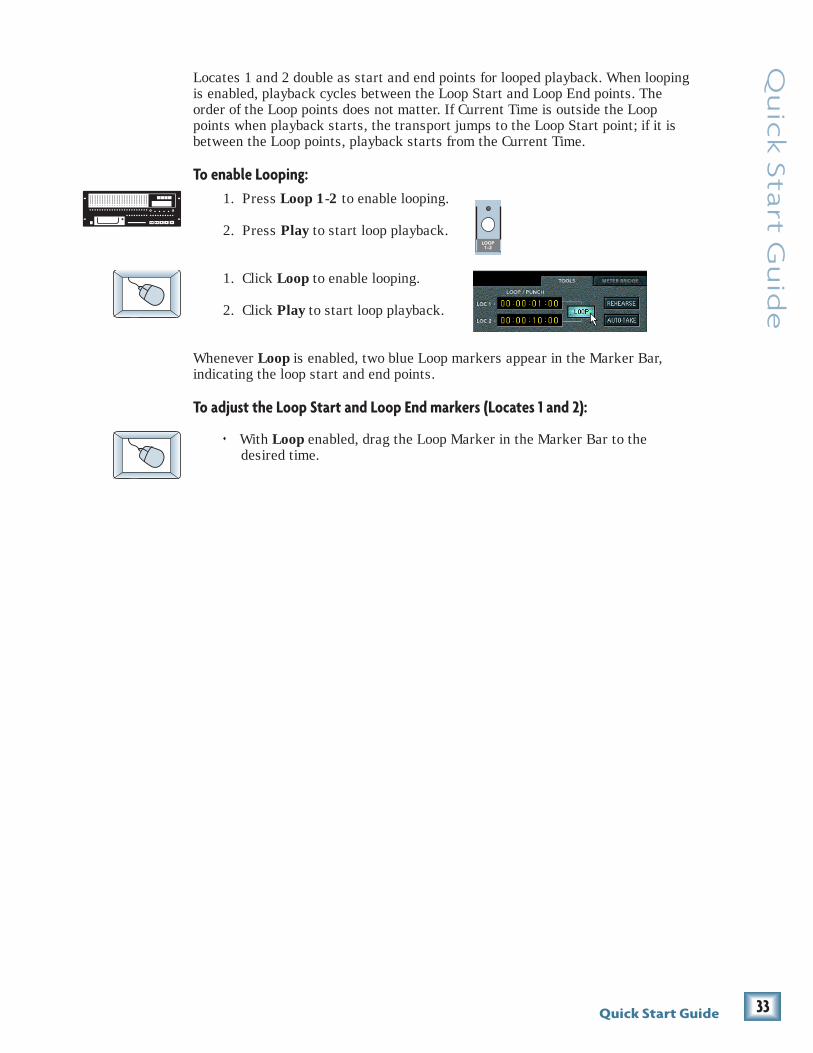
Locates 1 and 2 double as start and end points for looped playback. When loopingis enabled, playback cycles between the Loop Start and Loop End points. Theorder of the Loop points does not matter. If Current Time is outside the Looppoints when playback starts, the transport jumps to the Loop Start point; if it isbetween the Loop points, playback starts from the Current Time.
To enable Looping:1. Press Loop 1-2 to enable looping.
2. Press Play to start loop playback.
1. Click Loop to enable looping.
2. Click Play to start loop playback.
Whenever Loop is enabled, two blue Loop markers appear in the Marker Bar,indicating the loop start and end points.
To adjust the Loop Start and Loop End markers (Locates 1 and 2):
♦ With Loop enabled, drag the Loop Marker in the Marker Bar to thedesired time.
34 HDR 24/96
HD
R 2
4/
96 Cues
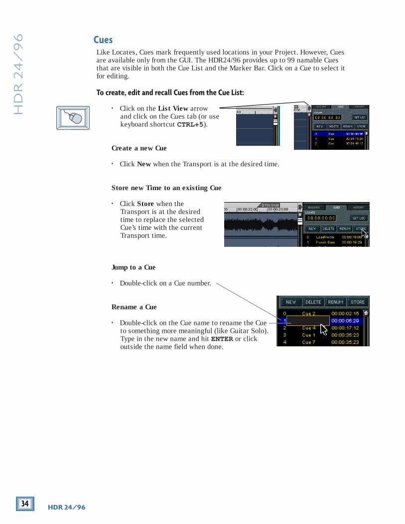
Like Locates, Cues mark frequently used locations in your Project. However, Cuesare available only from the GUI. The HDR24/96 provides up to 99 namable Cuesthat are visible in both the Cue List and the Marker Bar. Click on a Cue to select itfor editing.
To create, edit and recall Cues from the Cue List:
♦ Click on the List View arrowand click on the Cues tab (or usekeyboard shortcut CTRL+5).
Create a new Cue
♦ Click New when the Transport is at the desired time.
Store new Time to an existing Cue
♦ Click Store when theTransport is at the desiredtime to replace the selectedCue’s time with the currentTransport time.
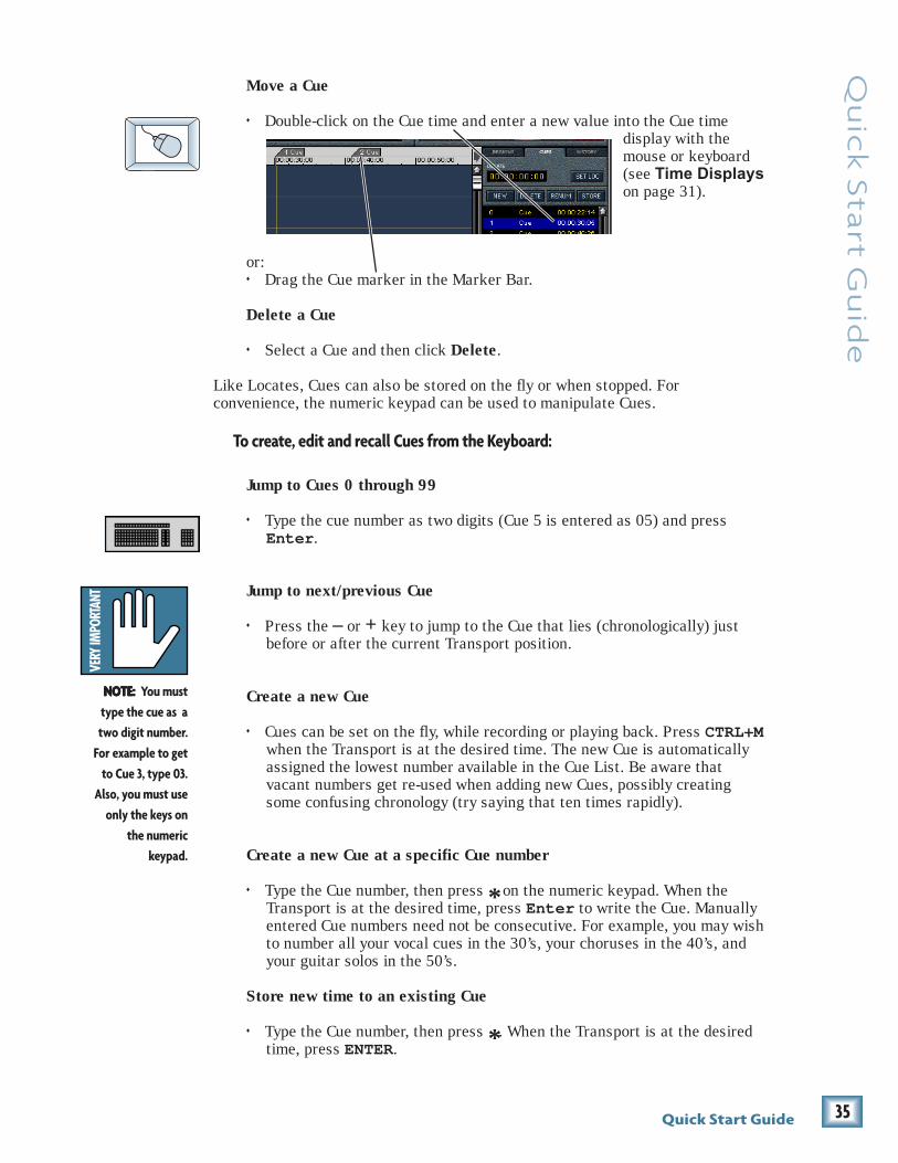
Jump to a Cue
♦ Double-click on a Cue number.
Rename a Cue
♦ Double-click on the Cue name to rename the Cueto something more meaningful (like Guitar Solo).Type in the new name and hit ENTER or clickoutside the name field when done.
35Quick Start Guide
Qu
ick S
tart G
uid
e
NOTE: NOTE: NOTE: NOTE: NOTE: You musttype the cue as atwo digit number.
For example to getto Cue 3, type 03.
Also, you must useonly the keys on
the numerickeypad.
Move a Cue
♦ Double-click on the Cue time and enter a new value into the Cue timedisplay with themouse or keyboard(see Time Displayson page 31).
or:♦ Drag the Cue marker in the Marker Bar.
Delete a Cue
♦ Select a Cue and then click Delete.
Like Locates, Cues can also be stored on the fly or when stopped. Forconvenience, the numeric keypad can be used to manipulate Cues.
To create, edit and recall Cues from the Keyboard:
Jump to Cues 0 through 99
♦ Type the cue number as two digits (Cue 5 is entered as 05) and pressEnter .
Jump to next/previous Cue
♦ Press the – or + key to jump to the Cue that lies (chronologically) justbefore or after the current Transport position.
Create a new Cue
♦ Cues can be set on the fly, while recording or playing back. Press CTRL+Mwhen the Transport is at the desired time. The new Cue is automaticallyassigned the lowest number available in the Cue List. Be aware thatvacant numbers get re-used when adding new Cues, possibly creatingsome confusing chronology (try saying that ten times rapidly).
Create a new Cue at a specific Cue number
♦ Type the Cue number, then press * on the numeric keypad. When theTransport is at the desired time, press Enter to write the Cue. Manuallyentered Cue numbers need not be consecutive. For example, you may wishto number all your vocal cues in the 30’s, your choruses in the 40’s, andyour guitar solos in the 50’s.
Store new time to an existing Cue
♦ Type the Cue number, then press *. When the Transport is at the desiredtime, press ENTER.

36 HDR 24/96
HD
R 2
4/
96
DISK UTILITY MENU Active Drive: Internal Set Mount Format Verify
Enter A Project Name: v Project#1 << >> New Cancel
Creating ProjectsNow that you have a few basics down, you’re ready to start recording. First, you’llneed to create a new Project. Typically a Project is a song, radio spot, or soundeffects stem for a 10-minute film reel, but it could also be a live concert or anentire symphony.
To create a new Project from the front panel:
1. Press Disk Util. The Disk UtilityMenu displays the Active Drive,which is the drive on which newProjects will be created.
2. If you want to create a newProject on a different drive, select Set. In the Set Active Drive menu, useeither the (–) Dec / (+) Inc or << / >> buttons to select either Internal orExternal. Select OK to confirm, then press Disk Util to exit. Otherwise,just press Disk Util to exit.
3. Press Project, then select New.The HDR24/96 asks if you wantto save the currently openProject. Press No to discardchanges you may have made tothe demo Project to keep it intactfor use with the tutorial in the Applications Manual.
4. The name “Project#1” appears onthe left side of the LCD screen. Apointer (“v”) appears above thefirst character of the name toindicate that you can change thatcharacter. Press the (–) Dec / (+)Inc buttons to select the characteryou want in that position. Select the >> button to move the pointer to thenext character.
5. When you’ve completed the Project name, select New to create the Projectand exit.
The HDR24/96 will not allow you to type the following characters into theProject, Track, Take, and Playlist names: / \ : * ? “ < > | . They are reservedfor use by the system.
PROJECT FILES MENU -> Active Drive:Internal New Open Save Delete

37Quick Start Guide
Qu
ick S
tart G
uid
e
PROJECT: Project#1 PLAYLIST: Playlist 1 DRIVE: C:Internal AVAIL: 01:35:00
Project#1I n te rna l
To create a new Project from the GUI:1. From the File menu select New
Project or use the keyboard shortcutCTRL+N. The HDR24/96 will ask ifyou want to save the currently openProject.
2. Click No to discard the changes youmade to the demo project and keep itintact for use with the tutorial.
3. In the New Project dialog box, select the drive you want to create theproject on from the Drive Select pulldown menu, then type in the projectname.
4. Click New.
Your new project is now open; theActive Drive, Project Name, andPlaylist Name are shown in the LCDdisplay and in the GUI above theCurrent Time display.
A Playlist is the part of a Project that keeps tracks of all your recordingand editing, and controls what you hear when you hit Play. The HDR24/96track display is the visual representation of the Playlist.
A Project can contain any number of Playlists. Since the audio recorded inone Playlist can be used in any Playlist, you can create multiple versions ofthe same song without affecting the original recording. For example, youcan create dance and extended play mixes from a CD mix. Or, you can buildan entirely new song and borrow parts from other Playlists. See theReference Manual to learn more about Playlists.
38 HDR 24/96
HD
R 2
4/
96 Naming Tracks
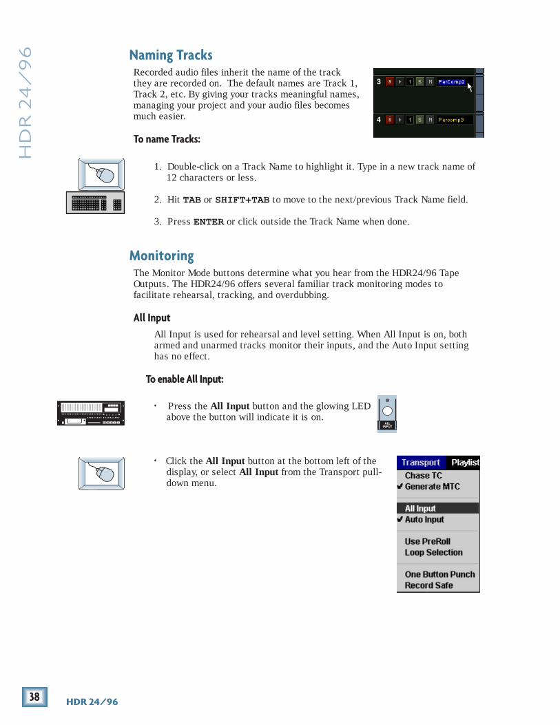
Recorded audio files inherit the name of the trackthey are recorded on. The default names are Track 1,Track 2, etc. By giving your tracks meaningful names,managing your project and your audio files becomesmuch easier.
To name Tracks:
1. Double-click on a Track Name to highlight it. Type in a new track name of12 characters or less.
2. Hit TAB or SHIFT+TAB to move to the next/previous Track Name field.
3. Press ENTER or click outside the Track Name when done.
MonitoringThe Monitor Mode buttons determine what you hear from the HDR24/96 TapeOutputs. The HDR24/96 offers several familiar track monitoring modes tofacilitate rehearsal, tracking, and overdubbing.
All InputAll Input is used for rehearsal and level setting. When All Input is on, botharmed and unarmed tracks monitor their inputs, and the Auto Input settinghas no effect.
To enable All Input:
♦ Press the All Input button and the glowing LEDabove the button will indicate it is on.
♦ Click the All Input button at the bottom left of thedisplay, or select All Input from the Transport pull-down menu.
ALLINPUT

39Quick Start Guide
Qu
ick S
tart G
uid
e
AUTOINPUT
Auto InputAuto Input is used for recording. Auto Input affects only tracks that are inRecord Ready (“armed”). Tracks that are not armed only monitor theplayback of previously recorded audio. To use Auto Input mode, All Inputmust be turned off.
When Auto Input is On, armed tracks monitor their inputs in Stop, FastForward, Rewind, and Record. In Play, you hear only what’s already recordedon the tracks. This mode is used primarily for tracking and overdubbing,where you want to hear what’s been previously recorded on the track untilthe punch-in and after the punch-out. During the punch, you hear what ispresently being recorded. Auto Input On is the default mode when you powerup the HDR24/96, and is the handiest mode for most people most of the time.
When Auto Input is Off, armed tracks always monitor their inputs. This modeis used primarily for rehearsal and tracking, where you want to always hearwhat you’re playing rather than what’s already recorded on that track.
To enable Auto Input:
♦ Press the Auto Input button. The glowingLED above the button indicates that it’s ON.
♦ Click the Auto Input button at the bottom right ofthe display, or select Auto Input from theTransport pulldown menu.

40 HDR 24/96
HD
R 2
4/
96
242322212019181716151413121110987654321
24TRACK/24BIT DIGITAL AUDIO HARD DISK RECORDER/EDITOR
OL
24
7
10152025
30354050
OL
24
7
10152025
30354050
OL
24
7
10152025
30354050
OL
24
7
10152025
30354050
OL
24
7
10152025
30354050
OL
24
7
10152025
30354050
OL
24
7
10152025
30354050
OL
24
7
10152025
30354050
OL
24
7
10152025
30354050
OL
24
7
10152025
30354050
OL
24
7
10152025
30354050
OL
24
7
10152025
30354050
OL
24
7
10152025
30354050
OL
24
7
10152025
30354050
OL
24
7
10152025
30354050
OL
24
7
10152025
30354050
OL
24
7
10152025
30354050
OL
24
7
10152025
30354050
OL
24
7
10152025
30354050
OL
24
7
10152025
30354050
OL
24
7
10152025
30354050
OL
24
7
10152025
30354050
OL
24
7
10152025
30354050
Metering and Setting Record LevelsA professional analog recorder has meters that indicate 0 VU at a +4 dBu nominalsignal level. Generally you can record peaks 10 to 15 dB above that beforedistortion becomes objectionable. This 10-15 dB range above the nominal level iscalled “headroom.”
On digital recorder meters, zero represents the full-scale digital signal level, 0dBFS for short. 0 dBFS is the hottest signal that a digital device can handle, withno headroom to spare. When a digital signal reaches 0 dBFS for more than asample or two, the resulting distortion is uglier than scraping your fingernailsacross a chalkboard.
The front panel meters are always available. In the GUI, the Meters panel spaceis shared with the the Tools panel. To switch displays, click on the Tools or Meterstab along the top right edge of the screen.
Remember, audio levels must NEVER reach 0 dBFS... never, ever, ever. Digitalclipping is an extremely nasty sound that could only pass for music if youlike what those crazy kids listen to over and over at all hours of the nights.
ALLINPUT
To get the get the best sound from the HDR24/96:
1. Turn All Input on.
2. Ask the talent to play or sing as loud as they will be performing during thesession. While watching the HDR24/96 meters, adjust the console’s tapeoutputs so that the signal peaks cause the red overload indicators to comeon occasionally. Then, back off the tape output level slightly. This insuresthe best fidelity and the widest dynamic range in the recorded signal andleaves you a little headroom to accommodate the talent’s enthusiasm.Keep the signal levels as high as possible without overload, becauserecording at lower levels reduces resolution and dynamic range.Nonetheless it is always better to be conservative and avoid the risk ofoverload than to try squeezing the last ounce of dynamic range from thesignal.

41Quick Start Guide
Qu
ick S
tart G
uid
e3. Alternately, if you have a tone generator or a sound source with a
constant volume (you can hold down a key on a synth), turn All Input onand send the tone to all 24 tracks of the console. Adjust the output levelsto read 0 VU on analog consoles, or around –20 dBFS on digital consoles.If the HDR24/96 meters read -15 to -20, you’re in good shape. This leavesenough headroom for most popular music, but if you’re recording acousticmusic, jazz, classical, or narration, you may want to leave a little more.When the talent starts to play you may have to make some final tweaks toget everything just right.
4. After adjusting the tape output levels for each console channel, followyour console manufacturer’s instructions for setting the console tapereturn levels.
The overload indicators on the HDR24/96 light when the signal level reaches–1 dBFS. In the GUI, the white track number above the Meters flashes redcontinuosly when the signal on that track clips (reaches 0 dBFS). If the tracksClip Indicator is lit, then turn down the console tape output to that track a bit.
To clear the Clip Indicator:
♦ Press Play.
♦ Click on the flashing track number, or click Play.
With analog I/O, a +22 dBu signal at the HDR24/96 inputs and outputs corresponds to 0 dBFSinside the HDR24/96. So, if your console has anominal output level (0 VU) of +4 dBu, there is18 dB of headroom before you hit the maximumrecord level on the HDR24/96. It also means thatyour console must be capable of putting out atleast +22 dBu without distortion so the consoledoesn’t clip while the recorder is still within itsworking range. Most professional consoles canoutput +22 dBu without breaking a sweat (likethe Mackie Analog and Digital 8•Bus consoles).But beware that semi-pro consoles often operateat a nominal output level of –10dBV and will run out of steam before reaching alevel that can take advantage of the recorder’s full resolution.
OL2
50
4710152025303540
+22 dBu
dBuequivalent
+20
–28 dBu
+18+15+12+7+2–3–8–13–18
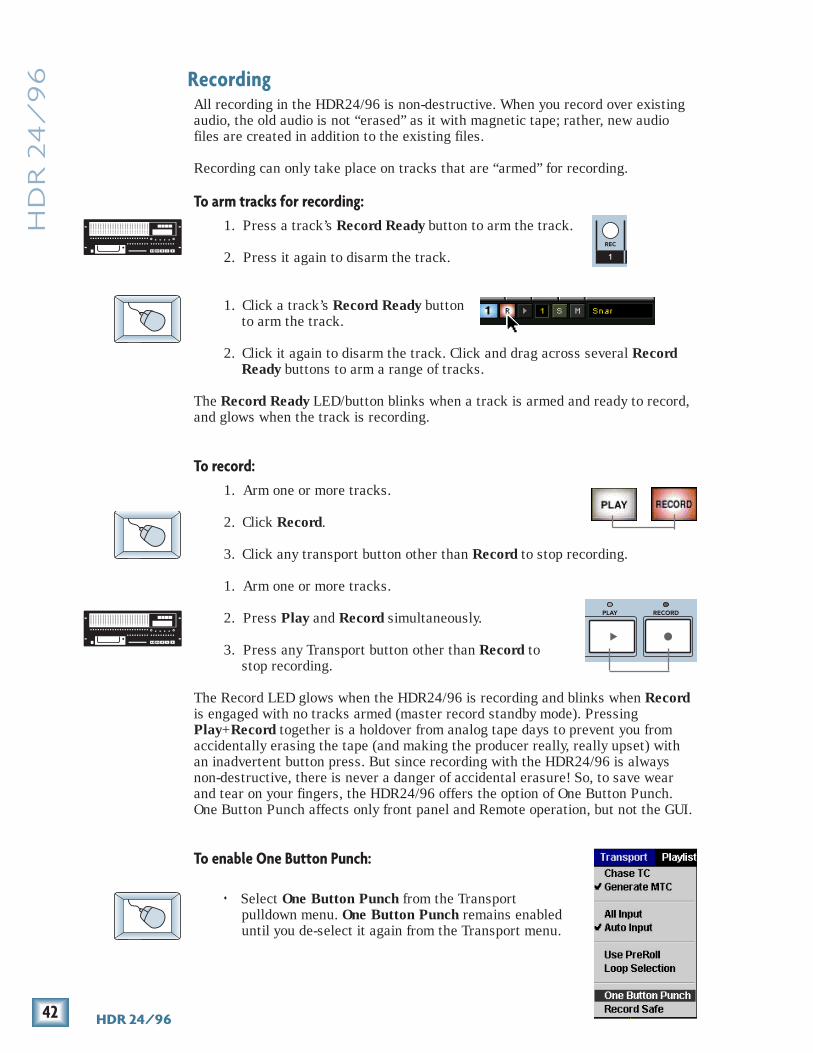
42 HDR 24/96
HD
R 2
4/
96 Recording
All recording in the HDR24/96 is non-destructive. When you record over existingaudio, the old audio is not “erased” as it with magnetic tape; rather, new audiofiles are created in addition to the existing files.
Recording can only take place on tracks that are “armed” for recording.
To arm tracks for recording:1. Press a track’s Record Ready button to arm the track.
2. Press it again to disarm the track.
1. Click a track’s Record Ready buttonto arm the track.
2. Click it again to disarm the track. Click and drag across several RecordReady buttons to arm a range of tracks.
The Record Ready LED/button blinks when a track is armed and ready to record,and glows when the track is recording.
To record:1. Arm one or more tracks.
2. Click Record.
3. Click any transport button other than Record to stop recording.
1. Arm one or more tracks.
2. Press Play and Record simultaneously.
3. Press any Transport button other than Record tostop recording.
The Record LED glows when the HDR24/96 is recording and blinks when Recordis engaged with no tracks armed (master record standby mode). PressingPlay+Record together is a holdover from analog tape days to prevent you fromaccidentally erasing the tape (and making the producer really, really upset) withan inadvertent button press. But since recording with the HDR24/96 is alwaysnon-destructive, there is never a danger of accidental erasure! So, to save wearand tear on your fingers, the HDR24/96 offers the option of One Button Punch.One Button Punch affects only front panel and Remote operation, but not the GUI.
To enable One Button Punch:
♦ Select One Button Punch from the Transportpulldown menu. One Button Punch remains enableduntil you de-select it again from the Transport menu.
1
REC
PLAY RECORD

43Quick Start Guide
Qu
ick S
tart G
uid
eTo record with One Button Punch enabled:
♦ From Play, Press Record; there is noneed to hold Play to start recording.Press any Transport button other thanRecord to stop recording.
When Record is engaged, you can punch in and out of record on individual tracksusing the Record Ready buttons. All of the recording methods sound the same,with no clicks or gaps. Arming tracks before pressing Record is usually the bestway to work when tracking, while pressing Record with no tracks armed (MasterRecord) and then punching with the Record Ready buttons is a handy way tooverdub individual tracks.
Record Safe disarms all tracks and disables all recording controls while itremains engaged.
To engage Record Safe:
♦ Press Rec Safe.
♦ Select Record Safe from the Transportpulldown menu.
RECORD
RECSAFE

44 HDR 24/96
HD
R 2
4/
96 Autopunch
Autopunch allows you to automatically punch in and out between two predefinedpoints. This feature is very convenient when you need to nail really a tight punchor need two hands to play your instrument. Numbered Locates 3 and 4 (availableon the GUI and the Remotes but not the front panel), double as the AutopunchPunch In and Punch Out points.
To enable Autopunch:♦ Click the Punch button.
When Punch is enabled, two red Punchmarkers appear in the Marker Bar.
To adjust the Punch In and Punch Out markers (Locates 3 and 4):♦ When the Transport is at the desired time, CTRL+click (the cursor will
turn into a hand) inside the numbered Locate time display. Or, when Punchis enabled, drag the Punch Marker in the Marker Bar to the desired time.
or:
♦ Enter the desired time directly into the numbered Locate time display withthe mouse or keyboard (see Time Displays on page 31).
To perform Autopunch recording:1. Arm one or more
Tracks, and park thetransportcomfortably beforethe Punch In point.You could use Loc1, Loc 2, or theTransport Locatepoint to get therequickly.
2. Press Play andRecord.
The Record LED blinks and the HDR24/96 plays. When Current Time reaches thePunch In point, the HDR24/96 begins recording on all armed tracks and theRecord LED glows. When Current Time reaches the Punch Out point, the HDR24/96 stops recording, the Record LED blinks, and the HDR24/96 continues playing.The order of the Punch points does not matter; the punch in always happens at theearlier point, and the punch out at the later point.
Use Loop and Autopunch together to do looped Autopunch recording. In thismode, your punch-in point must be no closer than 3 seconds to the loop startpoint. The loop end point must be at least 3 seconds later than the punch-outpoint.

45Quick Start Guide
Qu
ick S
tart G
uid
e
Footswitch
Footswitch OperationUsing a footswitch with the HDR24/96 gives you hands-free access to several ofthe most-used HDR24/96 functions. The footswitch is extremely handy when youwant to use your hands for other tasks, like playing your instrument, working theconsole, or eating pizza. Punching in and out is probably the most common use ofthe footswitch, but it can do other tricks as well.
Punch punches-in just like pressing Play+Record and punches-out likehitting Play. When playing, hitting the footswitch punches-in on all armedtracks. When recording, hitting the footswitch again punches-out of Record,but leaves the transport in Play.
Stop/Play acts just like the SPACEBAR on the keyboard. When theTransport is stopped, it puts it into play; when moving, it stops the Transport.
Next Cue acts just like the + key on the numeric keypad and locates theTransport to the next chronological Cue in the Project. When the Transport islocated on or after the last Cue, it locates back to the first Cue.
New Cue creates a new Cue. The Cue is automatically assigned the lowestnumber available in the Cue List.
To assign the footswitch function:1. Press the System button. In the System menu, select Footswitch HDR.
Then select Punch, Stop/Play, Next Cue, or New Cue from the HDRFootswitch mode menu.
2. Select OK, and press System again to exit.
1. Select Setup from the Windows menu (or use keyboard shortcut CTRL+1)and click on the General icon.
2. Select Punch, Stop/Play, Next Cue, or New Cue from the Footswitchpulldown menu.
3. Click the arrow in the top right corner of the dialog or hit ESC to exit.
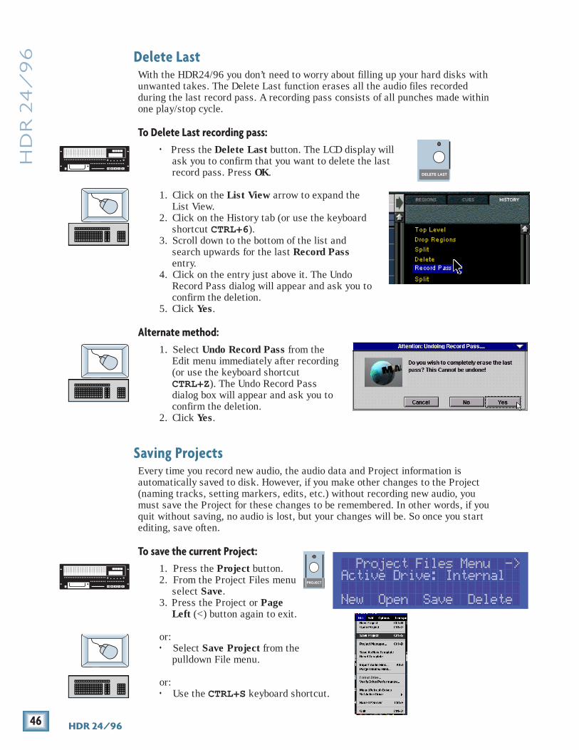
46 HDR 24/96
HD
R 2
4/
96 Delete Last
With the HDR24/96 you don’t need to worry about filling up your hard disks withunwanted takes. The Delete Last function erases all the audio files recordedduring the last record pass. A recording pass consists of all punches made withinone play/stop cycle.
To Delete Last recording pass:♦ Press the Delete Last button. The LCD display will
ask you to confirm that you want to delete the lastrecord pass. Press OK.
1. Click on the List View arrow to expand theList View.
2. Click on the History tab (or use the keyboardshortcut CTRL+6).
3. Scroll down to the bottom of the list andsearch upwards for the last Record Passentry.
4. Click on the entry just above it. The UndoRecord Pass dialog will appear and ask you toconfirm the deletion.
5. Click Yes.
Alternate method:1. Select Undo Record Pass from the
Edit menu immediately after recording(or use the keyboard shortcutCTRL+Z). The Undo Record Passdialog box will appear and ask you toconfirm the deletion.
2. Click Yes.
Saving ProjectsEvery time you record new audio, the audio data and Project information isautomatically saved to disk. However, if you make other changes to the Project(naming tracks, setting markers, edits, etc.) without recording new audio, youmust save the Project for these changes to be remembered. In other words, if youquit without saving, no audio is lost, but your changes will be. So once you startediting, save often.
To save the current Project:1. Press the Project button.2. From the Project Files menu
select Save.3. Press the Project or Page
Left (<) button again to exit.
or:♦ Select Save Project from the
pulldown File menu.
or:♦ Use the CTRL+S keyboard shortcut.
DELETE LAST
PROJECT B
Project Files Menu -> Active Drive: Internal New Open Save Delete
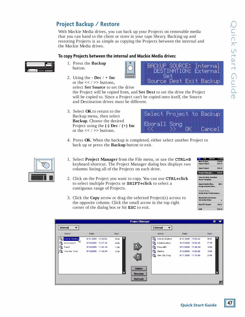
47Quick Start Guide
Qu
ick S
tart G
uid
e
T BACKUP D
Project Backup / RestoreWith Mackie Media drives, you can back up your Projects on removable mediathat you can hand to the client or store in your tape library. Backing up andrestoring Projects is as simple as copying the Projects between the internal andthe Mackie Media drives.
To copy Projects between the internal and Mackie Media drives:1. Press the Backup
button.
2. Using the - Dec / + Incor the << / >> buttons,select Set Source to set the drivethe Project will be copied from, and Set Dest to set the drive the Projectwill be copied to. Since a Project can’t be copied onto itself, the Sourceand Destination drives must be different.
3. Select OK to return to theBackup menu, then selectBackup. Choose the desiredProject using the (-) Dec / (+) Incor the << / >> buttons.
4. Press OK. When the backup is completed, either select another Project toback up or press the Backup button to exit.
1. Select Project Manager from the File menu, or use the CTRL+Bkeyboard shortcut. The Project Manager dialog box displays twocolumns listing all of the Projects on each drive.
2. Click on the Project you want to copy. You can use CTRL+clickto select multiple Projects or SHIFT+click to select acontiguous range of Projects.
3. Click the Copy arrow or drag the selected Project(s) across tothe opposite column. Click the small arrow in the top rightcorner of the dialog box or hit ESC to exit.
BACKUP SOURCE: Internal DESTINATION: External Set Source Dest Exit Backup
Select Project to Backup Eborall Song << >> OK Cancel

48 HDR 24/96
HD
R 2
4/
96
DISK UTILITY MENU Active Drive: Internal Set Mount Format Verify
It is extremely important that you make backup copies of your projects at the endof each session. While digital recording technology is highly reliable and hard diskmedia is durable, sometimes stuff just happens. To reduce your risk ofcatastrophic data loss (and the possible loss of $$ and clients), back up yourprojects on two media before deleting them from your working drive(s).
There…..now you know better. So, don’t wait until disaster strikes to get backupfever, and don’t complain to Mackie when your pet Rottweiler discovers that theonly copy of your client’s $20,000 project makes a superb chew toy and buries it inthe garden.
All media must be formatted before it can be used with the HDR24/96. Formattingerases the media’s contents and prepares the file system for use with the HDR24/96. Mackie Media M•90 drives come pre-formatted and ready to use, as do ORBdisks for the Mackie Media PROJECT drive (be sure to buy IBM formatted ORBdisks). Most off-the-shelf UDMA IDE drives do not come pre-formatted.
Although you can use almost any IDE drive for backup, not all UDMA IDE drivesare fast enough to be used for recording and playback. If you want to use your ownUDMA IDE drive for recording and playback, you must format it with the HDR,then verify that it is fast enough to record and playback at the maximum data rate(24 track, 24-bit, 48 kHz). If the drive passes the performance verification test, itis “tagged” as a real-time drive. If it fails, then the drive can be used only forbackup. External drives that fail the record verification test will appear with anasterisk (*) in the GUI and front panel menus and dialogs.
To format and verify media performance from the HDR24/96:
1. Press the Disk Util button. If theActive drive is not the externaldrive, then select Set.
2. In the Set Active Drive menu, useeither the – Dec / + Inc or << />> buttons and select External(Mackie Media bay).
3. Select OK. Now select Format. The LCD screen will display a messageasking you to confirm the format operation.
4. Select OK. When the format operation has completed, another messagewill appear asking you to verify the drive speed for recording andplayback.
5. If a UDMA drive is installed, select OK. After the performance verificationis completed, select Continue. If a Mackie Media PROJECT drive isinstalled, select Cancel; they are too slow to be used for recording andplayback.
6. Press Disk Util to exit.

49Quick Start Guide
Qu
ick S
tart G
uid
e
There! You’re all boned up on the HDR24/96, so put down this booklet and get towork ... or play. Thanks for reading this guide. If questions have goneunanswered, check the Applications and Reference Manuals or Mackie’s websitewww.mackie.com. Enjoy!
®
1. Select Set Active Drive from the File menu.
2. Select External.
3. Select Format Drive from the File menu and click OK inthe Format Drive confirmation dialog box.
4. When the format operation has completed, anothermessage will appear asking you to verify the drive speedfor recording and playback. If a UDMA drive is installed,select OK. After the performance verification is completed,select Continue. If a Mackie Media PROJECT drive isinstalled, select Cancel; they are too slow to be used forrecording and playback. NOTE: You cannot format theinternal drive.
Some UDMA drives cannot keep up with the demand for 24 tracks of audio data.So, before you rush to your local computer store and buy the cheapest UDMAdrive you can find, consider picking up some Mackie Media drives from yournearest Mackie dealer instead (nudge nudge, say no more…). If you still insist onthe do-it-yourself route, check Mackie’s web site for a list of approved drives.
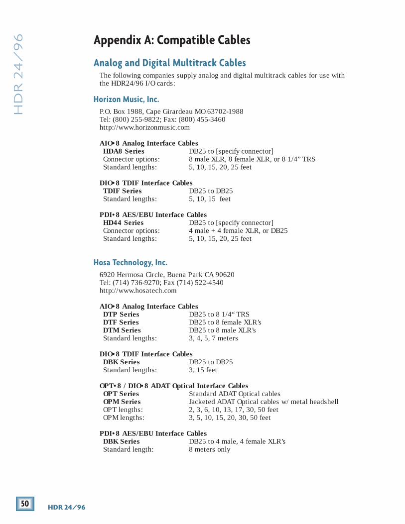
50 HDR 24/96
HD
R 2
4/
96 Appendix A: Compatible Cables
Analog and Digital Multitrack CablesThe following companies supply analog and digital multitrack cables for use withthe HDR24/96 I/O cards:
Horizon Music, Inc.P.O. Box 1988, Cape Girardeau MO 63702-1988Tel: (800) 255-9822; Fax: (800) 455-3460http://www.horizonmusic.com
AIO•8 Analog Interface CablesHDA8 Series DB25 to [specify connector]Connector options: 8 male XLR, 8 female XLR, or 8 1/4” TRSStandard lengths: 5, 10, 15, 20, 25 feet
DIO•8 TDIF Interface CablesTDIF Series DB25 to DB25Standard lengths: 5, 10, 15 feet
PDI•8 AES/EBU Interface CablesHD44 Series DB25 to [specify connector]Connector options: 4 male + 4 female XLR, or DB25Standard lengths: 5, 10, 15, 20, 25 feet
Hosa Technology, Inc.6920 Hermosa Circle, Buena Park CA 90620Tel: (714) 736-9270; Fax (714) 522-4540http://www.hosatech.com
AIO•8 Analog Interface CablesDTP Series DB25 to 8 1/4“ TRSDTF Series DB25 to 8 female XLR’sDTM Series DB25 to 8 male XLR’sStandard lengths: 3, 4, 5, 7 meters
DIO•8 TDIF Interface CablesDBK Series DB25 to DB25Standard lengths: 3, 15 feet
OPT•8 / DIO•8 ADAT Optical Interface CablesOPT Series Standard ADAT Optical cablesOPM Series Jacketed ADAT Optical cables w/ metal headshellOPT lengths: 2, 3, 6, 10, 13, 17, 30, 50 feetOPM lengths: 3, 5, 10, 15, 20, 30, 50 feet
PDI•8 AES/EBU Interface CablesDBK Series DB25 to 4 male, 4 female XLR’sStandard length: 8 meters only

51Quick Start Guide
Qu
ick S
tart G
uid
e
Marshall ElectronicsPO Box 2027, Culver City, CA 90231Tel: (800) 800-6608; Fax: (310) 391-8926http://www.mars-cam.com/cable.html
AIO•8 Analog Interface CablesDC-DAXM Series DB25 to 8 male XLR’sDC-DAXF Series DB25 to 8 female XLR’sDC-DAS Series DB25 to 8 1/4” TRS connectorsStandard lengths: 3, 5, 10, 15, 20, 25 feet
DIO•8 TDIF Interface CablesDCD-88D Series DB25 to DB25.Standard lengths: 1, 3, 6, 12, 15, 20, 25, 33 feet.
PDI•8 AES/EBU Interface CablesDC-SYX Series DB25 to 4 male, 4 female XLR’sDC-DUB Series DB25 to DB25Standard lengths: 3, 5, 10, 15, 20, 25 feet
Pro Co Sound, Inc.135 E. Kalamazoo Ave., Kalamazoo, MI 49007Tel: (800) 253-7360; Fax: (616) 388-9681http://ww.procosound.com
AIO•8 Analog Interface CablesDA-88 XM Series DB25 to 8 male XLR’sDA-88 XF Series DB25 to 8 female XLR’sDA-88 BQ Series DB25 to 8 1/4“ TRS connectorsStandard lengths: 5, 10, 15, 20 feet
Other CablesIn addition to the companies listed above, the following companies supplyindividual 110Ω AES/EBU and/or 75Ω word clock and video cables:
Apogee Electronics Corporation3145 Donald Douglas Loop SouthSanta Monica, CA 90405-3210Tel: (310) 915-1000; Fax: (310) 391-6262http://www.apogeedigital.com
Canare531 5th Street, Unit A, San Fernando, CA 91340Tel: (818) 365-2446; Fax: (818) 365-0479http://www.canare.com
Whirlwind99 Ling Rd., Rochester, NY 14612Tel: (888) 733-4396; Fax: (716) 865-8930http://www.whirlwindusa.com

52 HDR 24/96
HD
R 2
4/
96
RE
WIN
DFA
ST F
WD
PLA
YST
OP
RE
CO
RD
SELE
CT
SELE
CT
SELE
CT
SELE
CT
ON
POW
ER
LOC
2LO
C 1
STO
RE
LOO
P1
–2R
EC
SAFE
AU
TOTA
KE
T-C
OD
EC
HA
SETR
AC
KD
ELE
TE L
AST
PR
OJE
CT
BA
CK
UP
DIS
K U
TIL
SYST
EM
DIG
I-I/O
SYN
CD
EC
INC
AU
TOIN
PU
TA
LLIN
PU
T
2423
2221
2019
1817
1615
1413
1211
109
87
65
43
21
2423
2221
2019
1817
1615
1413
1211
109
87
65
43
21
HD
R 2
4/
24
TR
AC
K/2
4B
IT D
IGIT
AL A
UD
IO H
AR
D D
ISK
RE
CO
RD
ER
/ED
ITO
R H
IGH
RE
SO
LU
TIO
N A
UD
IO
44
.1/4
8/9
6K
SA
MP
LE
RA
TE
S
RE
CR
EC
RE
CR
EC
RE
CR
EC
RE
CR
EC
RE
CR
EC
RE
CR
EC
RE
CR
EC
RE
CR
EC
RE
CR
EC
RE
CR
EC
RE
CR
EC
RE
CR
EC
96
MIN
UTE
SH
OU
RSSE
CO
ND
SFR
AM
ES
TIC
KS
BEAT
SB
AR
S
44.1
k
VA
RI
48k
24 B
IT
ER
RO
R
96k
16 B
IT
TCC
LOC
K
OL 2 4 7 10 15 20 25 30 35 40 50
OL 2 4 7 10 15 20 25 30 35 40 50
OL 2 4 7 10 15 20 25 30 35 40 50
OL 2 4 7 10 15 20 25 30 35 40 50
OL 2 4 7 10 15 20 25 30 35 40 50
OL 2 4 7 10 15 20 25 30 35 40 50
OL 2 4 7 10 15 20 25 30 35 40 50
OL 2 4 7 10 15 20 25 30 35 40 50
OL 2 4 7 10 15 20 25 30 35 40 50
OL 2 4 7 10 15 20 25 30 35 40 50
OL 2 4 7 10 15 20 25 30 35 40 50
OL 2 4 7 10 15 20 25 30 35 40 50
OL 2 4 7 10 15 20 25 30 35 40 50
OL 2 4 7 10 15 20 25 30 35 40 50
OL 2 4 7 10 15 20 25 30 35 40 50
OL 2 4 7 10 15 20 25 30 35 40 50
OL 2 4 7 10 15 20 25 30 35 40 50
OL 2 4 7 10 15 20 25 30 35 40 50
OL 2 4 7 10 15 20 25 30 35 40 50
OL 2 4 7 10 15 20 25 30 35 40 50
OL 2 4 7 10 15 20 25 30 35 40 50
OL 2 4 7 10 15 20 25 30 35 40 50
OL 2 4 7 10 15 20 25 30 35 40 50
PROJECT: Little love
PLAYLIST: Playlist 1
DRIVE: C:Internal
AVAIL: 01:35:00
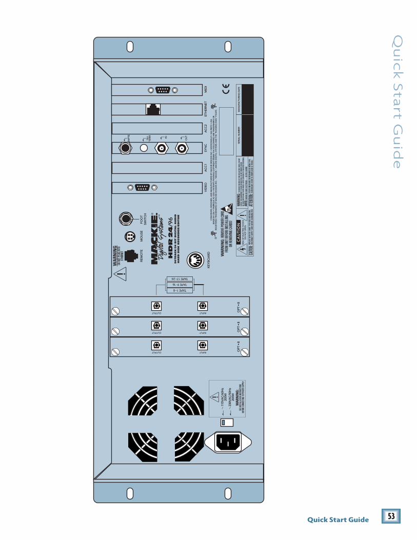
53Quick Start Guide
Qu
ick S
tart G
uid
e

54 HDR 24/96
HD
R 2
4/
96 Troubleshooting and service
Although you probably won’t need them, troubleshooting tips can be found in theReference Manual. Technical support is available by contacting your Mackiedealer, calling Mackie Designs at (800) 258-6883 (8:00 AM to 5:00 PM PacificTime), or visiting Mackie’s website at www.mackie.com.
Please read the included warranty information, then complete and return theincluded Warranty Registration card, or it’s straight to bed for you with no dinner.
ColophonQuick Start Guide text composed by Dana Bourke, based on a ballet by JeffGilbert. It was made possible by the teachings and donations of the HDR24/96Design Team, most notably Brian McCully and Bob Tudor. Graphics and layoutwere performed by Tony “Waldog” Baird with technical support from Steve Eboralland Frank “Weasel Boy” Heller. Cover art courtesy of Bryan Tiller. Long-windedexplanations, editing, and last minute updates from Mike Rivers, withproofreading and final blessing by Jeff Gilbert. Proofreading and additional editingby Linn Compton. Scott Garside was a pain the whole time.
Demo Music CreditsOde to Masters
Written by: Jay Roberts and Rick ReidPublished By: Nigel Nose MusicElectric Guitar: Jay RobertsClassical Guitar: Rick ReidBass: Dan DeanDrums: Brendan ScanlanHammond B3: Joey DeFrancescoTrumpet: Joey DeFrancesco
Little Bit of LoveWritten by: Claude Gaudette & Alan Roy Scott BMI #877477Published by: KYUSHU BOY MUSIC BMI #231306319Artist: Shirley MeyersProduction Company: Leggett Music Inc. Nashville Tn.Produced by: Keith OlsenArranged by: Claude Gaudette and Keith OlsenKeyboards: Claude Gaudette, Richard BakerGuitars: Tim PierceEngineered by: Keith Olsen and Peter LoveRecorded and Programmed at Goodnight LA Studios, Los Angeles
“Mackie,” the “Running Man” figure, “HDR24/96,” and “Digital 8•Bus” aretrademarks or registered trademarks of Mackie Designs Inc. All other brandnames mentioned are trademarks or registered trademarks of their respectiveholders, and are hereby acknowledged.
®
© 2000 Mackie Designs Inc.All Rights Reserved.Printed in the U.S.A.

55Quick Start Guide
Qu
ick S
tart G
uid
e
Notes________________________________________________________________________________________________________________________________________________________________________________________________________________________________________________________________________________________________________________________________________________________________________________________________________________________________________________________________________________________________________________________________________________________________________________________________________________________________________________________________________________________________________________________________________________________________________________________________________________________________________________________________________________________________________________________________________________________________________________________________________________________________________________________________________________________________________________________________________________________________________________________________________________________________________________________________________________________________________________________________________________________________________________________________________________________________________________________________________________________________________________________________________________________________________________________________________________________________________________________________________________________________________________________________________________________________________________________________________________________________________________________________________________________________________________________________________________________________________________________________________________________________________________________________________________________________________________________________________________________________________________________________________________________________________________________________________________________________________________________________________________________________________________________________________________________________________________________________________________________________________________________________________________________________________________________________________________________________________________________________________________________________________________________________________________________________________________________________________________________________________________________________________________________________________________________________________________________________________________________________________________________________________________________________________________________________________________________________________________________________________________________________________________________________________________________________________________________________________________________________________________________________________________________________________________________________________________________________________________________________________________________________________________________________________________________________________________________________________________________________________________________________________________________________________________________________________________________________________________________________________________________________________________________________________________________________________________________________________________________________________________________________________________________________________________________________________________________________________________________________________________________________________________________________________________________________________________________________________________________________________________________________________________________________________________________________________________________________________________________________________________________________________________________________________________________________________________________________________________________________________________________________________________________________________________________________________________________________________________________________________________________________________________________________________________________________________________________________________________________________________________________________________________________________________________________________________________________________________________________________________________________________________________________________________________________________________________________________