head loss calculations - memphis · 2012-10-10 · head loss calculations bernoulli and pipe flow !...
TRANSCRIPT

1
Civil Engineering Hydraulics Mechanics of Fluids
Head Loss Calculations
Bernoulli and Pipe Flow
¢ The Bernoulli equation that we worked with was a bit simplistic in the way it looked at a fluid system
¢ All real systems that are in motion suffer from some type of loss due to friction
¢ It takes something to move over a rough surface
Pipe Flow 2

2
Bernoulli and Pipe Flow
¢ Consider flow in a constant-diameter pipe
Pipe Flow 3
Bernoulli and Pipe Flow
¢ If we look at the energy at points 1 and 2.
Pipe Flow 4
p1ρ
+v12
2+ z1g =
p2ρ
+v22
2+ z2g

3
Bernoulli and Pipe Flow
¢ Since this system is horizontal, z1 = z2 so
Pipe Flow 5
p1ρ
+v12
2=p2ρ
+v22
2
Bernoulli and Pipe Flow
¢ The pipe has a constant diameter and the flow is constant at both sections so the velocity at each point is the same.
Pipe Flow 6
v1 = v2
p1
ρ+
v12
2=
p2
ρ+
v22
2p1
ρ=
p2
ρ

4
Bernoulli and Pipe Flow
¢ Since we are dealing with an uncompressible fluid, the pressures at points 1 and 2 should be the same.
Pipe Flow 7
p1ρ
=p2ρ
⇒ p1 = p2
Bernoulli and Pipe Flow
¢ If we ran the system experimentally and measured the two pressures, they would not be the same.
Pipe Flow 8
p1ρ
=p2ρ
⇒ p1 = p2

5
Bernoulli and Pipe Flow
¢ The pressure at point 2 would be lower than the pressure at point 1.
Pipe Flow 9
p1ρ
=p2ρ
⇒ p1 = p2
Bernoulli and Pipe Flow
¢ The pressure is being lost (actually the pressure energy) due to friction as the flow moves along the pipe.
Pipe Flow 10
p1ρ
=p2ρ
⇒ p1 = p2

6
Friction Losses
¢ To be able to quantify what is happening we need to look an element of flow in the pipe.
Pipe Flow 11
Friction Losses
¢ The grey element on the right is an element of the flow, a slice like a quarter.
Pipe Flow 12

7
Friction Losses
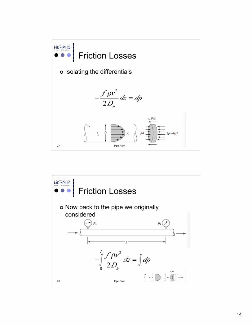
¢ The thickness of the quarter is dz and it has a perimeter length of P (πD)
¢ This makes the area in contact with the sides of the pipe equal to Pdz = πDdz
¢ At the wall there is a shearing stress, τw, which is the stress between the wall and the outer layer of the fluid
Pipe Flow 13
Friction Losses
¢ Then the force from the wall on the section of fluid (opposing the fluid flow) will be equal to
Pipe Flow 14
Fretarding = τwPdz = τwπDdz

8
Friction Losses
¢ The pressure on the upstream (left face) of the section will produce a force accelerating the section
Pipe Flow 15
Fretarding = τwPdz = τwπDdz
Faccelerating = pA = p πD2
4
Friction Losses
¢ As we move from the left face to the right face (dz) the change in pressure will equal dp
Pipe Flow 16
Fretarding = τwPdz = τwπDdz
Faccelerating = pA = p πD2
4

9
Friction Losses
¢ So this will add an additional retarding force
Pipe Flow 17
Fretarding = τwπDdz + p + dp( )πD2
4
Faccelerating = pA = p πD2
4
Friction Losses
¢ Since both the velocity and mass flow rates as the same on both sides of the section, there is no net force on the section (conservation of momentum)
Pipe Flow 18
Fretarding = τwπDdz + p + dp( )πD2
4
Faccelerating = pA = p πD2
4Faccelerating − Fretarding = 0

10
Friction Losses
¢ Therefore
Pipe Flow 19
Fretarding = τwπDdz + p + dp( )πD2
4
Faccelerating = pA = p πD2
4Faccelerating − Fretarding = 0
p πD2
4−τwπDdz − p + dp( )πD
2
4= 0
−τwπDdz −πD 2
4dp = 0
Friction Losses
¢ Rearranging
Pipe Flow 20
−τwπDdz −πD 2
4dp = 0
−τwπDdz =πD 2
4dp
−τwπDπD 2
4
= dpdz

11
Friction Losses
¢ So we have an expression for the rate at which the pressure changes as the flow moves downstream
Pipe Flow 21
−τwπDdz −πD 2
4dp = 0
−τwπDdz =πD 2
4dp
−τwπDπD 2
4
= dpdz
Friction Losses
¢ In the simplest form
Pipe Flow 22
−τwπDπD 2
4
= dpdz
−4τwD
= dpdz

12
Friction Losses
¢ Generalizing to any shape pipe we substitute the hydraulic diameter for the pipe diameter
Pipe Flow 23
−4τwDh
= dpdz
Friction Losses
¢ At this point, we can introduce another dimensionless ratio, the friction factor, f
Pipe Flow 24
−4τwDh
= dpdz

13
Friction Losses
¢ The friction factor, f, is the ratio of the friction forces to the inertia forces.
Pipe Flow 25
−4τwDh
= dpdz
f =4τw12ρv 2
Friction Losses
¢ Combining the two expressions.
Pipe Flow 26
−f 12ρv 2
Dh= dpdz
14
Friction Losses
¢ Isolating the differentials
Pipe Flow 27
− f ρv2
2Dhdz = dp
Friction Losses
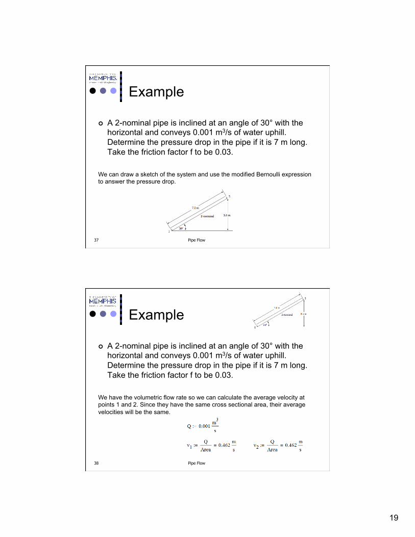
¢ Now back to the pipe we originally considered
Pipe Flow 28
− f ρv 2
2Dhdz
0
L
∫ = dp∫

15
Friction Losses
¢ Integrating
Pipe Flow 29
− f ρv 2
2Dhdz
0
L
∫ = dp∫
− fLρv2
2Dh= p2 − p1
Friction Losses
¢ Usually we break this expression into two terms
Pipe Flow 30
− fLρv2
2Dh= − ρv 2
2fLDh
= p2 − p1

16
Friction Losses
¢ So we have a modified form of the Bernoulli equation that takes into account the friction losses in the system
Pipe Flow 31
p1ρ
+v12
2+ z1g −
ρv 2
2fLDh
ρ
⎡
⎣
⎢⎢⎢⎢
⎤
⎦
⎥⎥⎥⎥
=p2ρ
+v22
2+ z2g
The pressure change term takes that form because we are using energy terms in this expression.
Friction Losses
¢ Reducing
Pipe Flow 32
p1ρ
+v12
2+ z1g − v
2
2fLDh
=p2ρ
+v22
2+ z2g

17
Friction Losses
¢ And rewriting the expression in terms of head
Pipe Flow 33
p1ρg
+v12
2g+ z1 −
v 2
2gfLDh
=p2ρg
+v22
2g+ z2
Friction Losses
¢ So the downstream energy (at point 2) is lower than the energy at point 1
Pipe Flow 34
p1ρg
+v12
2g+ z1 −
v 2
2gfLDh
=p2ρg
+v22
2g+ z2

18
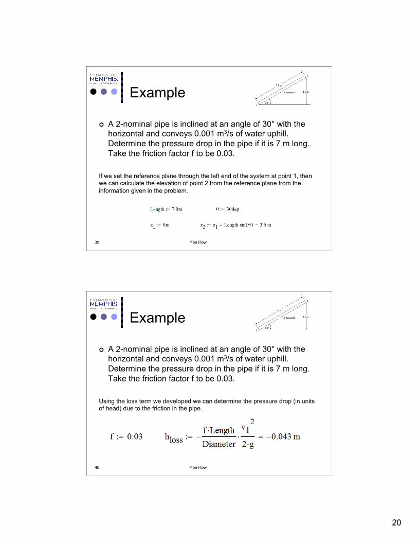
Example
¢ A 2-nominal pipe is inclined at an angle of 30° with the horizontal and conveys 0.001 m3/s of water uphill. Determine the pressure drop in the pipe if it is 7 m long. Take the friction factor f to be 0.03.
Pipe Flow 35
Example
¢ A 2-nominal pipe is inclined at an angle of 30° with the horizontal and conveys 0.001 m3/s of water uphill. Determine the pressure drop in the pipe if it is 7 m long. Take the friction factor f to be 0.03.
Pipe Flow 36
The 2-nominal refers to the pipe size. At one time, it would have been the inside diameter of the pipe in inches but that is no longer the case. Like the 2 by 4 in lumber, it is now just a reference. Table C.1 in the back of the book gives the critical dimensions for the pipe. If no schedule (has to do with wall thickness and strength of the pipe) you may assume that it is the most common, Schedule 40.
19
Example
¢ A 2-nominal pipe is inclined at an angle of 30° with the horizontal and conveys 0.001 m3/s of water uphill. Determine the pressure drop in the pipe if it is 7 m long. Take the friction factor f to be 0.03.
Pipe Flow 37
We can draw a sketch of the system and use the modified Bernoulli expression to answer the pressure drop.
Example
¢ A 2-nominal pipe is inclined at an angle of 30° with the horizontal and conveys 0.001 m3/s of water uphill. Determine the pressure drop in the pipe if it is 7 m long. Take the friction factor f to be 0.03.
Pipe Flow 38
We have the volumetric flow rate so we can calculate the average velocity at points 1 and 2. Since they have the same cross sectional area, their average velocities will be the same.
20
Example
¢ A 2-nominal pipe is inclined at an angle of 30° with the horizontal and conveys 0.001 m3/s of water uphill. Determine the pressure drop in the pipe if it is 7 m long. Take the friction factor f to be 0.03.
Pipe Flow 39
If we set the reference plane through the left end of the system at point 1, then we can calculate the elevation of point 2 from the reference plane from the information given in the problem.
Example
¢ A 2-nominal pipe is inclined at an angle of 30° with the horizontal and conveys 0.001 m3/s of water uphill. Determine the pressure drop in the pipe if it is 7 m long. Take the friction factor f to be 0.03.
Pipe Flow 40
Using the loss term we developed we can determine the pressure drop (in units of head) due to the friction in the pipe.
21
Example
¢ A 2-nominal pipe is inclined at an angle of 30° with the horizontal and conveys 0.001 m3/s of water uphill. Determine the pressure drop in the pipe if it is 7 m long. Take the friction factor f to be 0.03.
Pipe Flow 41
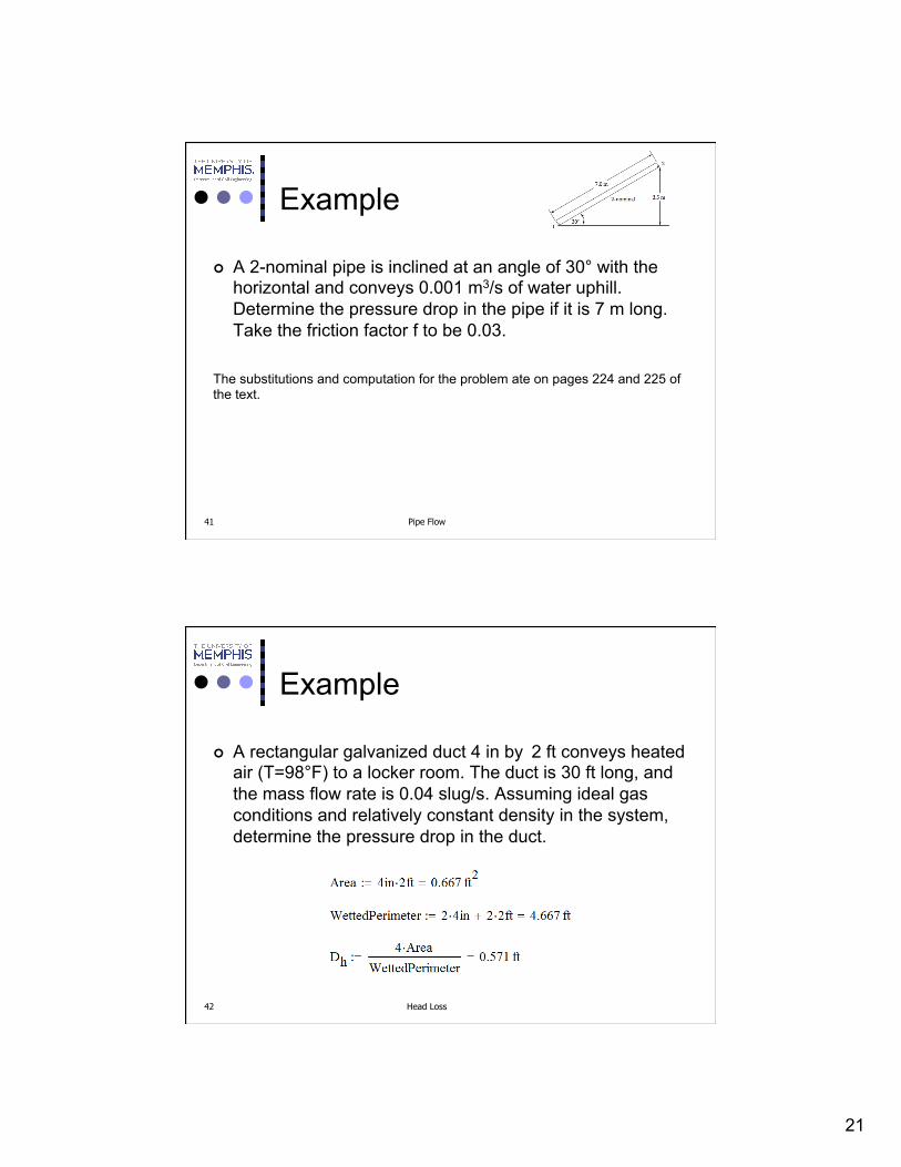
The substitutions and computation for the problem ate on pages 224 and 225 of the text.
Example
¢ A rectangular galvanized duct 4 in by 2 ft conveys heated air (T=98°F) to a locker room. The duct is 30 ft long, and the mass flow rate is 0.04 slug/s. Assuming ideal gas conditions and relatively constant density in the system, determine the pressure drop in the duct.
Head Loss 42

22
Example
¢ A rectangular galvanized duct 4 in by 2 ft conveys heated air (T=98°F) to a locker room. The duct is 30 ft long, and the mass flow rate is 0.04 slug/s. Assuming ideal gas conditions and relatively constant density in the system, determine the pressure drop in the duct.
Head Loss 43
Example
¢ A rectangular galvanized duct 4 in by 2 ft conveys heated air (T=98°F) to a locker room. The duct is 30 ft long, and the mass flow rate is 0.04 slug/s. Assuming ideal gas conditions and relatively constant density in the system, determine the pressure drop in the duct.
Head Loss 44

23
Example
¢ A rectangular galvanized duct 4 in by 2 ft conveys heated air (T=98°F) to a locker room. The duct is 30 ft long, and the mass flow rate is 0.04 slug/s. Assuming ideal gas conditions and relatively constant density in the system, determine the pressure drop in the duct.
Head Loss 45
We have the length of the pipe, the hydraulic diameter, the mass density of the fluid, and the velocity. What we don’t have is the friction factor for this flow. There is no simple way to calculate this. Under some flow regimes, there is a good approximation but to make the calculation we first need to calculate the Reynolds number of the flow and the relative roughness of the pipe.
Example
¢ A rectangular galvanized duct 4 in by 2 ft conveys heated air (T=98°F) to a locker room. The duct is 30 ft long, and the mass flow rate is 0.04 slug/s. Assuming ideal gas conditions and relatively constant density in the system, determine the pressure drop in the duct.
Head Loss 46
For most common piping materials, we can find what is known as the characteristic dimension of wall roughness which is given the symbol, ε (epsilon). Table 5.2 in the chapter gives some examples of values for ε. In this example, the conduit is galvanized so ε in feet is shown.

24
Example
¢ A rectangular galvanized duct 4 in by 2 ft conveys heated air (T=98°F) to a locker room. The duct is 30 ft long, and the mass flow rate is 0.04 slug/s. Assuming ideal gas conditions and relatively constant density in the system, determine the pressure drop in the duct.
Head Loss 47
We now calculate a new dimensionless ratio known as the relative roughness which is the ratio of the characteristic roughness to the hydraulic diameter.
Example
¢ A rectangular galvanized duct 4 in by 2 ft conveys heated air (T=98°F) to a locker room. The duct is 30 ft long, and the mass flow rate is 0.04 slug/s. Assuming ideal gas conditions and relatively constant density in the system, determine the pressure drop in the duct.
Head Loss 48
We also need to calculate the Reynolds number of the flow.

25
Example
¢ A rectangular galvanized duct 4 in by 2 ft conveys heated air (T=98°F) to a locker room. The duct is 30 ft long, and the mass flow rate is 0.04 slug/s. Assuming ideal gas conditions and relatively constant density in the system, determine the pressure drop in the duct.
Head Loss 49
If the flow had been laminar, we could have used 64/Re to calculate f. Since this flow is turbulent, we have to use the Moody Diagram.
Figure 5.15 page 229
Moody Diagram
Head Loss 50
On the right side of the diagram we locate a curve representing the relative roughness.

26
Moody Diagram
Head Loss 51
On the right side of the diagram we locate a curve representing the relative roughness.
On the bottom of the diagram, we locate the Reynolds number.
Moody Diagram
Head Loss 52
On the right side of the diagram we locate a curve representing the relative roughness.
On the bottom of the diagram, we locate the Reynolds number.
Move straight up from the Reynolds Number until you intersect with the curve representing the relative roughness.

27
Moody Diagram
Head Loss 53
On the right side of the diagram we locate a curve representing the relative roughness.
On the bottom of the diagram, we locate the Reynolds number.
Move straight up from the Reynolds Number until you intersect with the curve representing the relative roughness.
Move from the intersection point to the left hand axis, that value is the friction factor.
Pipe Flow 54
Homework 18-1
¢ A 4-nominal riveted steel pipe 35 m long is laid horizontally and is to convey castor oil at a rate of 0.1 m3/s. Determine the pressure drop in the pipe.

28
Pipe Flow 55
Homework 18-2
¢ A 12-standard, type K copper tube conveys water at a rate of 1 800 gpm. If the tube is 15 ft long, determine the pressure drop.
Pipe Flow 56
Homework 18-3
¢ A 15-ft-long annulus made of 4-nominal, schedule 40 pipe and 2-nominal, schedule 40 pipe conveys carbon disulfide at a volume flow rate of 0.3 ft3/s. Determine the pressure drop over the 15-ft length. Both pipes are made of cast iron.