head loss in irrigation pipe couplers
TRANSCRIPT
Louisiana State UniversityLSU Digital Commons
LSU Agricultural Experiment Station Reports LSU AgCenter
1962
Head loss in irrigation pipe couplersWilliam F. Lytle
Follow this and additional works at: http://digitalcommons.lsu.edu/agexp
This Article is brought to you for free and open access by the LSU AgCenter at LSU Digital Commons. It has been accepted for inclusion in LSUAgricultural Experiment Station Reports by an authorized administrator of LSU Digital Commons. For more information, please [email protected].
Recommended CitationLytle, William F., "Head loss in irrigation pipe couplers" (1962). LSU Agricultural Experiment Station Reports. 107.http://digitalcommons.lsu.edu/agexp/107

HeadIrrigation
i ^
Pipe Couplers
W. F, Lyfle and James E. Wimberly
553
Louisiana State University and
Agricultural and Mechanical College
Agricultural Experiment Station
Charles W. Upp, Director
CONTENTS
Page
Introduction 3
Procedure ^
Description of Couplers 7
Results 8
Discussion 1^
Summary and Conclusions IS
Literature Cited 15
2

Head Loss in Irrigation Pipe CouplersW. F. Lytle^ and James E. Wimberly^
INTRODUCTION
Irrigation systems contain pipe, fittings, and couplers, each of which
causes head loss in the system. Several methods have been used to de-
termine the actual head loss in portable irrigation pipe with quick
couplers. One of the most practiced methods is using Scobey's Equation.
This equation, when used with a friction coefficient, results in the
total head loss of the system. The friction coefficient commonly used
is 0.40, which is sufficient to cover loss in the pipe, couplers, and fittings
that may be used.
The sprinkler Irrigation Handbook (5) presents a head loss table
for aluminum irrigation pipe with couplers. The table is based on
Scobey's Equation using Ks = 0.34 for 2-inch pipe, Ks = 0.33 for 3-inch
pipe and Ks = 0.32 for pipe of all other sizes.
Some irrigation engineers use Scobey's Equation in their design workwith varied friction coefficients.
Scobey's Equation for aluminum irrigation systems is:
Ks LVi-9rll
1000.0 Dl l
Where Hf = total friction loss in feet of water
Ks = Scobey's friction coefficient
L = length of pipe in feet
V = mean velocity in feet per second
D = internal diameter in feet
W. O. Ree (3) in a report on "Head Loss in Quick-Coupled Alumi-
num Pipe" showed results of some tests previously conducted with calcu-
lations of coefficients from three formulas. These were Scobey's formula,
the Manning formula, and the Hazen-Williams formula. Relationships
were then worked out to convert the friction loss values to coefficients for
the more common formulas. In addition to these formulas, some de-
signers use the head loss of a coupler in equivalent feet of pipe and Hf —Kc (V2/2g) where Hf = total head loss and Kc — friction coefficient.
The authors have conducted a study of several different types andsizes of quick couplers. This study was conducted as Project 894 of the
Louisiana State University Agricultural Experiment Station. The study
was to determine the actual head loss from individual couplers. Withthis value known, the design of an irrigation system could be moreexact, and information gained might help in the future design of
couplers. This study is the subject of this report.
^Assistant Professor, Agricultural Engineering (Resigned July 1, 1961).
2Assistant Professor, Agricultural Engineering.
3
4
PROCEDURE
Most manufacturers of irrigation pipe quick couplers supplied a
coupler of each size and type. Only 3-, 4-, 5-, and 6-inch couplers were
tested. The flo^v of ^vater was obtained by a gas engine-driven centrifugal
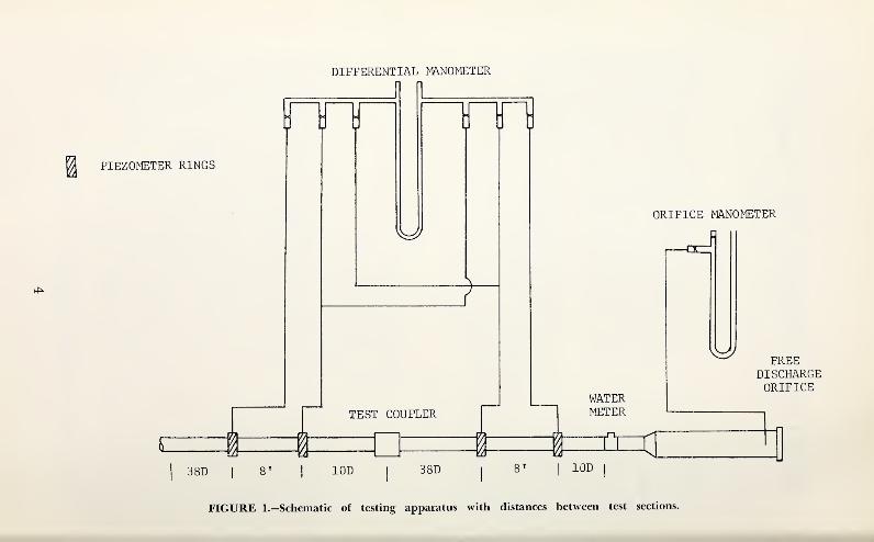
pump. Flow direction is sho^vn in Figure 1, along with the distances be-
tween pipe test section and coupler. The lengths of straight pipe up-
stream and do^vnstream from the test points were sufficient to insure
uniform flow conditions at the test points.
The flow rates were measured by a calibrated orifice and an in-line
Tvater meter, and were controlled b) a valve upstream from the orifice
meter.
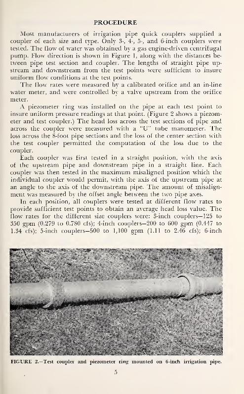
A piezometer ring ^vas installed on the pipe at each test point to
insure uniform pressure readings at that point. (Figure 2 shows a piezom-
eter and test coupler.) The head loss across the test sections of pipe andacross the coupler ivere measured with a "U" tube manometer. Theloss across the 8-foot pipe sections and the loss of the center section ^s'ith
the test coupler permitted the computation of the loss due to the
coupler.
Each coupler ^\a.s first tested in a straight position, ^vith the axis
of the upstream pipe and downstream pipe in a straight line. Eachcoupler was then tested in the maximum misaligned position which the
individual coupler Tvould permit, M'ith the axis of the upstream pipe at
an angle to the axis of the downstream pipe. The amount of misalign-
ment ^vas measured by the offset angle between the t^vo pipe axes.
In each position, all couplers were tested at different flow rates to
provide sufficient test points to obtain an average head loss value. Theflow rates for the different size couplers were: 3-inch couplers— 125 to
350 gpm (0.279 to 0.780 cfs); 4-inch couplers-200 to 600 gpm (0.447 to
1.34 cfs); 5-inch couplers—500 to 1,100 gpm (1.11 to 2.46 cfs); 6-inch
300 1000
Q (gpm)
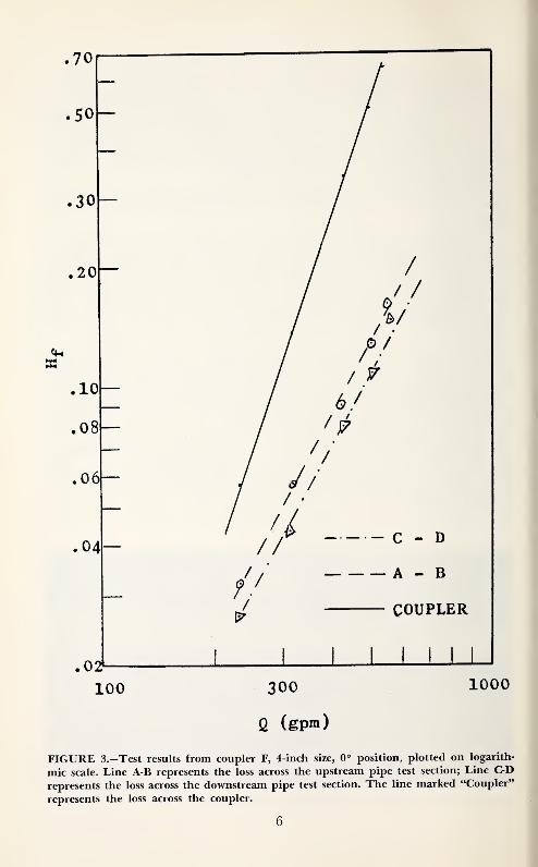
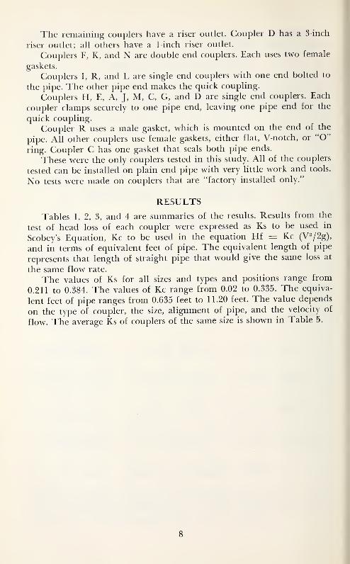
FIGURE 3.—Test results from coupler F, 4-inch size, 0° position, plotted on logarith-
mic scale. Line A-B represents the loss across the upstream pipe test section; Line C-D
represents the loss across the downstream pipe test section. The line marked "Coupler"
represents the loss across the coupler.
6
couplers—800 to 1,500 gpm (1.78 to 3.35 c£s) . The test results were
plotted as shown in Figure 3.
DESCRIPTION OF COUPLERS
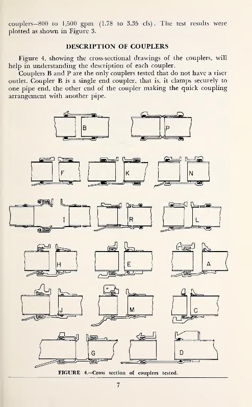
Figure 4, showing the cross-sectional drawings of the couplers, will
help in understanding the description of each coupler.
Couplers B and P are the only couplers tested that do not have a riser
outlet. Coupler B is a single end coupler, that is, it clamps securely to
one pipe end, the other end of the coupler making the quick coupling
arrangement with another pipe.
FIGURE 4.—Cross section of couplers tested.
7
The remaining couplers have a riser outlet. Coupler D has a 3-inch
riser outlet; all others have a 1-inch riser outlet.
Couplers F, K, and N are double end couplers. Each uses two female
gaskets.
Couplers 1, R, and L are single end couplers with one end bolted to
the pipe. The other pipe end makes the quick coupling.
Couplers H, E, A, J, M, C, G, and D are single end couplers. Each
coupler clamps securely to one pipe end, leaving one pipe end for the
quick coupling.
Coupler R uses a male gasket, which is mounted on the end of the
pipe. All other couplers use female gaskets, either flat, V-notch, or "O"
ring. Coupler C has one gasket that seals both pipe ends.
These were the only couplers tested in this study. All of the couplers
tested can be installed on plain end pipe with very little work and tools.
No tests were made on couplers that are "factory installed only."
RESULTS
Tables 1, 2, 3, and 4 are summaries of the results. Results from the
test of head loss of each coupler were expressed as Ks to be used in
Scobey's Equation, Kc to be used in the equation Hf = Kc (V2/2g),
and in terms of equivalent feet of pipe. The equivalent length of pipe
represents that length of straight pipe that would give the same loss at
the same flow rate.
The values of Ks for all sizes and types and positions range from
0.211 to 0.384. The values of Kc range from 0.02 to 0.335. The equiva-
lent feet of pipe ranges from 0.635 feet to 11.20 feet. The value depends
on the type of coupler, the size, alignment of pipe, and the velocity of
flow. The average Ks of couplers of the same size is shown in Table 5.
8

T-AJBLE 1.—Head Loss and Coefficients of 3-Inch Couplers in the Straight and
Misaligned Positions
Head loss in
Misalignment equivalent
Coupler (degreesj feet of pipe Ks Kc
A 0 1.39 .246 .075
11.4 2.55 .260 .147
B 0 1.27 .248 .062
11.4 2-97 .281 .i4o
C 0 0.63 .226 .031
8.8 1.65 .237 .087
D 0 3.71 .273 .201
10.0 5.75 .319 .322
E 0 0.64 .247 .036
14.2 4.03 .273 .147
G 0 1.41 .242 .076
10.6 3.26 .274 .178
I 0 2.87 .279 .147
16.0 4.57O Q O.232
J 0 0.71 .262 .031
11.4 1.04 .299 .051
K 0 1.44 .248 .118
11.4 2.40 .260 .123
L 0 2.05 .248 .114
7.7 2.49 .280 .138
M 0 1.30 .241 .067
11.4 2.03 .262 .100
N 0 1.46 .248 .076
8.7 1.81 .261 .085
9
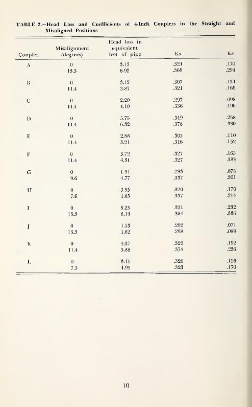
TABLE 2 -Head Loss and Coefficients of 4-Inch Couplers in the Straight and
Misaligned Positions
Coupler
Misalignment
(degrees)
Head loss in
equivalent
feet of pipe Ks Kc
A 0 3.13 .324 .170
13.3 6.92 .369 .294
B 0 3.12 .307 .134
11.4 3.87 .321 .165
C 0 2.20 .297 .098
11.4 4.10 .336 .196
D 0 5.75 .349 .258
11.4 6.32 .378 .330
E 0 2.88 .305 .110
11.4 3.21 .316 .152
F 0 3.72 .327 .165
11.4 4.31 .327 .183
G 0 1.91 .293 .078
9.6 4.77 .337 .201
H 0 3.95 .320 .170
7.6 4.65 .337 .214
I 0 5.25 .321 .232
13.3 8.14 .384 .335
J 0 1.53 .292 .071
13.3 1.82 .298 .089
K 0 4.37 .329 .192
11.4 5.88 .374 .236
L 0 3.45 .320 .126
7.5 4.95 .323 .170
10
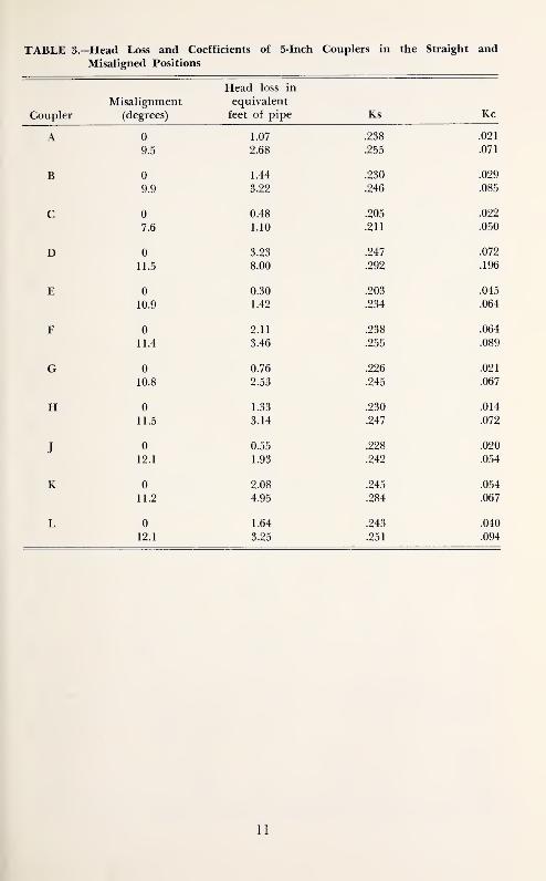
TABLE 3.—Head Loss and Coefficients of 5-Inch Couplers in the Straight and
Misaligned Positions
Coupler
Misalignment
(degrees)
Head loss in
equivalent
feet of pipe Ks Kc
0 1.07 .238 .021
9.5 2.68 .255 .071
0 1.44 .230 .029
9.9 3.22 .246 .085
0 0.48 .205 .022
7.6 1.10 .211 .050
D 0 3.23 .247 .072
11.5 8.00 .292 .196
E 0 0.30 .203 .045
10.9 1.42 .234 .064
F 0 2.11 .238 .064
11.4 3.46 .255 .089
G 0 0.76 .226 .021
10.8 2.53 .245 .067
H 0 1.33 .230 .014
11.5 3.14 .247 .072
TJ 0 0.55 .228 .020
12.1 1.93 .242 .054
K 0 2.08 .245 .054
11.2 4.95 .284 .067
L 0 1.64 .243 .040
12.1 3.25 .251 .094
11

TABLE 4.-Head Loss and Coefficients of 6-Inch Couplers in the Straight and
Misaligned Positions
Head loss in
Misalignment equivalentKcCoupler (desrees) feet of pipe Ks
A 0 .085
10.9 6.72 .276 .103
B 0 l.o/ .404
13.4 6.60 .299 .152
C 0 i.D4 •404 .037
12.1 2.44 .256 .063
D 0 A QrtD.yu .400 .157
5.3 8.35 .303 .214
E A L.OD .40D .030
9.3 2.78 .252 .083
F 0 .4t:0 .050
10.0 2.80 .259 .052
G 0 94<^.4t:0 .034
9.0 4.40 .266 .110
H 0 9 1/1 94-9.4t:4 .049
9.2 3.09 .255 .074
I 0 4.DO .400
22.6 11.20 .333 .245
J 0 A-Oo 94.Q .vfJ4
11.6 3.92 .262 .072
K 0 5.05 .4/0
9.6 6.40 .283 .147
L 0 55 /I 1 .ouo .yjou
8.0 4.32 .319 .112
M 0 1 .'±1 99Q 027.U4 /
10.2 3.66 .259 .087
P 0 3.60 .259 .083
9.2 3.80 .259 .087
R 0 6.00 .283 .134
7.6 6.40 .286 .152
TABLE 5.—Average Ks and Equivalent Feet of Pipe of Couplers of the Same Size*
Diameter Ks Variation from Equivalent
mean average feet of pipe
3 inches 0.25 0.046 1.47
4 inches 0.31 0.051 3.15
5 inches 0.23 0.044 1.58
6 inches 0.26 0.052 3.35
*Averages based on couplers where all four sizes were of the same type.
12
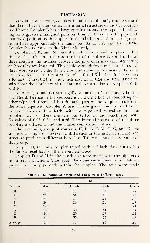
DISCUSSION
As pointed out earlier, couplers B and P are the only couplers tested
that do not have a riser outlet. The internal structure of the two couplers
is different. Coupler B has a large opening around the pipe ends, allow-
ing for a greater misaligned position. Coupler P restricts the pipe ends
to a fixed position. Both couplers in the 6-inch size and in a straight po-
sition have approximately the same loss (Ks — 0.25 and Ks = 0.26).
Coupler P was tested in the 6-inch size only.
Couplers F, K, and N were the only double end couplers with a
riser outlet. The internal construction of the three is similar. In all
three couplers the distance between the pipe ends may vary, depending
on how they are installed. This could cause differences in head loss. All
three were tested in the 3-inch size, and show approximately the same
head loss, Ks = 0.24, 0.25, 0.25. Couplers F and K in the 4-inch size have
a Ks = 0.33 and 0.33; in the 5-inch size, Ks = 0.24 and 0.24. These re-
sults show the similarity of the internal construction of couplers F, K,
and N.
Couplers I, R, and L fasten rigidly to one end of the pipe, by bolting
on. The difference in the couplers is in the method of connecting the
other pipe end. Coupler I has the male part of the coupler attached to
the other pipe end. Coupler R uses a male gasket and external latch.
Coupler L uses only a latch, with the pipe end extending into the
coupler. Each of these couplers was tested in the 6-inch size, with
Ks values of 0.27, 0.31, and 0.26. The internal structure of the three
couplers is different, and this makes comparison difficult.
The remaining group of couplers, H, E, A, J, M, C, G, and D, are
single end couplers. However, a difference in the internal surface and
structure produces a different head loss. Table 6 shows the Ks value of
this group.
Coupler D, the only coupler tested with a 3-inch riser outlet, has
the largest head loss of all the couplers tested.
Couplers D and H in the 4-inch size were tested with the pipe ends
in different positions. This could be done since there is no defined
position of the pipe ends within the coupler. The tests were made
TABLE 6.-KS Values of Single End Couplers of Different Sizes
Ks
Coupler 3-Inch 4-Inch 5-Inch 6-Inch
H .32 .23 .24
E .25 .31 .20 .24
A .25 .32 .24 .27
J .26 .29 .23 .25
M .24 .23
C .23 .30 .21 .23
G .24 .29 .23 .25
D .27 .35 .25 .29
Average .25 .31 .23 .25
13
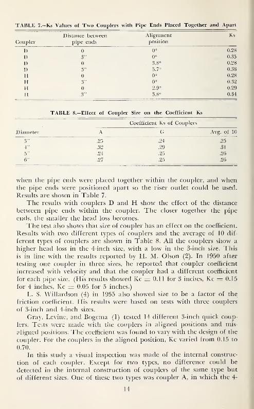
TABLE 7.—Ks Values of Two Couplers with Pipe Ends Placed Together and Apart
Distance between. Alignment Ks
Coupler pipe ends position
D 0 0° 0.28
D 3" 0° 0.35
D 0 3.8° 0.28
D 3" 5.7° 0.38
H 0 0° 0.28
H 3" 0° 0.32ITrl Au 0.29
H 3" 3.8° 0.34
TABLE 8.-Effect of Coupler Size on the Coefficient Ks
Coefficient Ks of Couplers
Diameter A G Avg. of 10
3" .25 .24 .25
4" .32 .29 .31
5" .24 .25 .26
6" .27 .25 .26
when the pipe ends were placed together within the coupler, and whenthe pipe ends were positioned apart so the riser outlet could be used.
Results are shown in Table 7.
The results with couplers D and H show the effect of the distance
between pipe ends within the coupler. The closer together the pipe
ends, the smaller the head loss becomes.
The test also shows that size of coupler has an effect on the coefficient.
Results with two different types of couplers and the average of 10 dif-
ferent types of couplers are shown in Table 8. All the couplers show a
higher head loss in the 4-inch size, with a low in the 3-inch size. This
is in line with the results reported by H. M. Olson (2). In 1950 after
testing one coupler in three sizes, he reported that coupler coefficient
increased with velocity and that the coupler had a different coefficient
for each pipe size. (His results showed Kc = 0.11 for 3 inches, Kc = 0.15
for 4 inches, Kc = 0.05 for 5 inches.)
L. S. Willardson (4) in 1955 also showed size to be a factor of the
friction coefficient. His results were based on tests with three couplers
of 3-inch and 4-inch sizes.
Gray, Levine, and Bogema (1) tested 14 different 3-inch quick coup-
lers. Tests were made with the couplers in aligned positions and mis-
aligned positions. The coefficient was found to vary with the design of the
coupler. For the couplers in the aligned position, Kc varied from 0.15 to
0.70.
In this study a visual inspection was made of the internal construc-
tion of each coupler. Except for two types, no difference could be
detected in the internal construction of couplers of the same type but
of different sizes. One of these two types was coupler A, in which the 4-
14
inch size has more abrupt changes in the contour Hnes than the other
sizes have. Coupler E has a rougher internal surface in the 3-inch size
than in the other sizes. These differences are probably due to the
different molds and have no appreciable effect on the head loss coeffi-
cient.
SUMMARY AND CONCLUSIONS
Head loss was determined on 16 different types of irrigation pipe
quick-couplers, most of which were tested in 3-, 4-, 5-, and 6-inch sizes.
Results of the test for each coupler are presented in three forms. Oneform is by expressing the loss of the coupler as loss of equivalent feet
of straight pipe. The other forms are coefficients Ks and Kc, which
can be used in empirical formulas for determining the total friction loss
of an irrigation system.
The head loss value varies considerably, and depends on the type of
coupler, the size of pipe, the alignment of the pipe joined in the coupler,
the distance between pipe ends in the coupler, and the velocity of the
flow through the coupler.
The known head loss in the different couplers will be valuable in
the future design of quick-couplers. The head loss per coupler will also
be useful when designing irrigation systems. For maximum efficiency of
an irrigation system the design coefficient should be the coefficient of the
coupler to be used.
LITERATURE CITED
1. Gray, H. E., G. Levine, and M. Bogema. Head Loss in Irrigation
Line Quick Couplers, Agricultural Engineering Journal, Novem-ber 1954, pp. 804-05.
2. Olson, H. M. The Determination of the Friction Factor for Newand Used Aluminum Tubing and Head Loss in Sprinkler-Pipe
Couplers. 1950 Unpublished Master's Thesis. Copy on file in Li-
brary, Utah State Univ.
3. Ree, W. O. Head Loss in Quick-Coupled Aluminum Pipe, Used for
Sprinkler Irrigation Systems. Agricultural Handbook No. 147,
United States Department of Agriculture.
4. WiLLiARDSON, L. S. Energy Losses in Aluminum Irrigation Pipe Dueto Deflections in the Couplers. 1955 Unpublished Master's Thesis.
Copy on file in Library, Utah State Univ.
5. Woodward, Guy O. Sprinkler Irrigation. 1959. Published by Sprink-
ler Irrigation Association, Washington 6, D. C.
15