hearing aid compatibility (hac) t-coil test report · 3.1 description of equipment under test ......
TRANSCRIPT

Sporton International (KunShan) INC. Page Number : 1 of 25
TEL : 86-0512-5790-0158 Report Issued Date : Jul. 10, 2017
FAX : 86-0512-5790-0958 Report Version : Rev. 01
FCC ID : SRQ-Z233VL
FCC HAC T-Coil Test Report Report No. : HA6O1901-03B
Hearing Aid Compatibility (HAC) T-Coil Test Report
APPLICANT : ZTE CORPORATION
EQUIPMENT : LTE/CDMA Multi-Mode Digital Mobile Phone
BRAND NAME : ZTE
MODEL NAME : Z233V
FCC ID : SRQ-Z233VL
STANDARD : FCC 47 CFR §20.19
ANSI C63.19-2011
We, Sporton International (KunShan) INC., would like to declare that the tested sample has
been evaluated in accordance with the procedures and shown the compliance with the
applicable technical standards.
The test results in this report apply exclusively to the tested model / sample. Without
written approval of Sporton International (KunShan) INC., the test report shall not be
reproduced except in full.
Sporton International (KunShan) INC. No.3-2, Pingxiang Road, Kunshan Development Zone, Jiangsu, China
Approved by: Jones Tsai / Manager
Prepared by: Mark Qu / Manager

Sporton International (KunShan) INC. Page Number : 2 of 25
TEL : 86-0512-5790-0158 Report Issued Date : Jul. 10, 2017
FAX : 86-0512-5790-0958 Report Version : Rev. 01
FCC ID : SRQ-Z233VL
FCC HAC T-Coil Test Report Report No. : HA6O1901-03B
Table of Contents 1. Attestation of Test Results ........................................................................................................................................ 4 2. Administration Data ................................................................................................................................................... 4 3. General Information ................................................................................................................................................... 5
3.1 Description of Equipment Under Test (EUT) ..................................................................................................... 5 3.2 Air Interface and Operating Mode ..................................................................................................................... 6 3.3 Applied Standards ............................................................................................................................................ 6
4. HAC T-Coil .................................................................................................................................................................. 7 4.1 T-Coil Coupling Field Intensity .......................................................................................................................... 7 4.2 T-Coil Frequency Response ............................................................................................................................. 7 4.3 T-Coil Signal Quality Categories ....................................................................................................................... 9
5. Measurement System Specification ........................................................................................................................10 5.1 System Configuration ......................................................................................................................................10 5.2 Test Arch Phantom ..........................................................................................................................................10 5.3 AMCC .............................................................................................................................................................. 11 5.4 AM1D Probe .................................................................................................................................................... 11 5.5 AMMI ...............................................................................................................................................................12 5.6 System Hardware ............................................................................................................................................12 5.7 Cabling of System for GSM / UMTS / CDMA...................................................................................................13 5.8 Cabling of System for VoLTE ...........................................................................................................................13 5.9 Test Equipment List .........................................................................................................................................14 5.10 Probe Calibration in AMCC ..............................................................................................................................15 5.11 Reference Input of Audio Signal Spectrum ......................................................................................................16 5.12 Establish Reference Level for VoLTE ..............................................................................................................17
6. T-Coil Test Procedure ...............................................................................................................................................18 6.1 Test Process and Flow Chart ...........................................................................................................................18 6.2 Description of EUT Test Position .....................................................................................................................21
7. HAC T-Coil Test Results ...........................................................................................................................................22 7.1 Preliminary Scan for VoLTE T-coil performance ..............................................................................................22 7.2 Magnitude Result for VoLTE ............................................................................................................................23
8. Uncertainty Assessment ..........................................................................................................................................24 9. References .................................................................................................................................................................25 Appendix A. Plots of T-Coil Measurement Appendix B. DASY Calibration Certificate Appendix C. Test Setup Photos Appendix D. Product Equality Declaration

Sporton International (KunShan) INC. Page Number : 3 of 25
TEL : 86-0512-5790-0158 Report Issued Date : Jul. 10, 2017
FAX : 86-0512-5790-0958 Report Version : Rev. 01
FCC ID : SRQ-Z233VL
FCC HAC T-Coil Test Report Report No. : HA6O1901-03B
Revision History
REPORT NO. VERSION DESCRIPTION ISSUED DATE
HA6O1901-03B Rev. 01 Initial issue of report Jul. 10, 2017

Sporton International (KunShan) INC. Page Number : 4 of 25
TEL : 86-0512-5790-0158 Report Issued Date : Jul. 10, 2017
FAX : 86-0512-5790-0958 Report Version : Rev. 01
FCC ID : SRQ-Z233VL
FCC HAC T-Coil Test Report Report No. : HA6O1901-03B
1. Attestation of Test Results
Applicant Name ZTE CORPORATION
Equipment Name LTE/CDMA Multi-Mode Digital Mobile Phone
Brand Name ZTE
Model Name Z233V
FCC ID SRQ-Z233VL
IMEI Code 990008870002230
HW Version Z233VHWV1.0
SW Version Z233VV1.0.0B01
EUT Stage Identical Prototype
HAC Rating T4
Date Tested 2017/7/6
Test Result Pass
The device is compliance with HAC limits specified in guidelines FCC 47CFR §20.19 and ANSI Standard ANSI C63.19.
2. Administration Data
Testing Site
Test Site Sporton International (KunShan) INC.
Test Site Location
No.3-2, Pingxiang Road, Kunshan Development Zone, Jiangsu, China
TEL: +86-0512-5790-0158
FAX: +86-0512-5790-0958
Test Site No. Sporton Site No. : SAR01-KS
Applicant
Company Name ZTE CORPORATION
Address ZTE Plaza, Keji Road South, Hi-Tech Industrial Park, Nanshan District, Shenzhen, Guangdong, 518057, P. R. China
Manufacturer
Company Name ZTE CORPORATION
Address ZTE Plaza, Keji Road South, Hi-Tech Industrial Park, Nanshan District, Shenzhen, Guangdong, 518057, P. R. China

Sporton International (KunShan) INC. Page Number : 5 of 25
TEL : 86-0512-5790-0158 Report Issued Date : Jul. 10, 2017
FAX : 86-0512-5790-0958 Report Version : Rev. 01
FCC ID : SRQ-Z233VL
FCC HAC T-Coil Test Report Report No. : HA6O1901-03B
3. General Information
3.1 Description of Equipment Under Test (EUT)
Product Feature & Specification
Frequency Band
CDMA2000 BC0: 824.7 MHz ~ 848.31 MHz CDMA 2000 BC1: 1851.25 MHz ~ 1908.75 MHz LTE Band 2: 1850 MHz ~ 1910 MHz LTE Band 4: 1710 MHz ~ 1755 MHz LTE Band 13: 777 MHz ~ 787 MHz Bluetooth: 2402 MHz ~ 2480 MHz
Mode
.CDMA2000 : 1xRTT/1xEv-Do(Rev.0)/1xEv-Do(Rev.A)
.LTE: QPSK, 16QAM
.Bluetooth v3.0+EDR, Bluetooth 4.0 LE
Remark: 1. This device supports VoLTE function. 2. This is a variant report for Z233V. The product equality declaration could be referred to Appendix D. All the test cases
were performed on the original test report which can be referred to Sporton Report Number HA6O1901B. Based on the original test report, only adding the LTE T-Coil test.

Sporton International (KunShan) INC. Page Number : 6 of 25
TEL : 86-0512-5790-0158 Report Issued Date : Jul. 10, 2017
FAX : 86-0512-5790-0958 Report Version : Rev. 01
FCC ID : SRQ-Z233VL
FCC HAC T-Coil Test Report Report No. : HA6O1901-03B
3.2 Air Interface and Operating Mode
Air Interface Band MHz Type
C63.19
Tested
Simultaneous
Transmitter OTT
Power
Reduction
CDMA
BC0 VO Yes
BT NA No
BC1 BT NA No
EVDO DT No BT Yes No
LTE
Band 2
VD Yes
BT Yes
No
Band 4 BT No
Band 13 BT No
BT 2450 DT No CDMA, LTE NA No
VO=CMRS Voice Service DT=Digital Transport VD=CMRS IP Voice Service and Digital Transport
3.3 Applied Standards
FCC CFR47 Part 20.19
ANSI C63.19 2011-version
FCC KDB 285076 D01 HAC Guidance v04r01
FCC KDB 285076 D02 T Coil testing for CMRS IP v02

Sporton International (KunShan) INC. Page Number : 7 of 25
TEL : 86-0512-5790-0158 Report Issued Date : Jul. 10, 2017
FAX : 86-0512-5790-0958 Report Version : Rev. 01
FCC ID : SRQ-Z233VL
FCC HAC T-Coil Test Report Report No. : HA6O1901-03B
4. HAC T-Coil
FCC wireless hearing aid compatibility rules ensure that consumers with hearing loss are able to access wireless communications services through a wide selection of handsets without experiencing disabling radio frequency (RF) interference or other technical obstacles. To define and measure the hearing aid compatibility of handsets, in CFR47 part 20.19 ANSI C63.19 is referenced. A handset is considered hearing aid-compatible for acoustic coupling if it meets a rating of at least M3 under ANSI C63.19, and A handset is considered hearing aid compatible for inductive coupling if it meets a rating of at least T3. For inductive coupling, the wireless communication devices should be measured as below. 1) Magnetic signal strength in the audio band 2) Magnetic signal frequency response through the audio band 3) Magnetic signal to noise
4.1 T-Coil Coupling Field Intensity
When measured as specified in this standard, the T-Coil signal shall be ≥ –18 dB (A/m) at 1 kHz, in a 1/3 octave band filter for all orientations.
4.2 T-Coil Frequency Response
The frequency response of the perpendicular component of the magnetic field, measured in 1/3 octave bands, shall follow the response curve specified in this sub-clause, over the frequency range 300 Hz to 3000 Hz. Figure 4.1 and Figure 4.2 provide the boundaries as a function of frequency. These response curves are for true field-strength measurements of the T-Coil signal. Thus, the 6 dB/octave probe response has been corrected from the raw readings.
Fig. 4.1 Magnetic field frequency response for WDs with field strength≤-15dB at 1 KHz

Sporton International (KunShan) INC. Page Number : 8 of 25
TEL : 86-0512-5790-0158 Report Issued Date : Jul. 10, 2017
FAX : 86-0512-5790-0958 Report Version : Rev. 01
FCC ID : SRQ-Z233VL
FCC HAC T-Coil Test Report Report No. : HA6O1901-03B
Fig. 4.2 Magnetic field frequency response for WDs with a field that exceeds –15 dB(A/m) at 1 kHz

Sporton International (KunShan) INC. Page Number : 9 of 25
TEL : 86-0512-5790-0158 Report Issued Date : Jul. 10, 2017
FAX : 86-0512-5790-0958 Report Version : Rev. 01
FCC ID : SRQ-Z233VL
FCC HAC T-Coil Test Report Report No. : HA6O1901-03B
4.3 T-Coil Signal Quality Categories
This section provides the signal quality requirement for the intended T-Coil signal from a WD. Only the RF
immunity of the hearing aid is measured in T-Coil mode. It is assumed that a hearing aid can have no
immunity to an interference signal in the audio band, which is the intended reception band for this mode.
A device is assessed beginning by determining the category of the RF environment in the area of the
T-Coil source.
The RF measurements made for the T-Coil evaluation are used to assign the category T1 through T4.
The limitation is given in Table 4.3. This establishes the RF environment presented by the WD to a
hearing aid.
Category Telephone parameters WD signal quality
((signal + noise) to noise ratio in dB)
Category T1 0 to 10 dB
Category T2 10 to 20 dB
Category T3 20 to 30 dB
Category T4 > 30 dB
Table 4.3 T-Coil Signal Quality Categories
Sporton International (KunShan) INC. Page Number : 10 of 25
TEL : 86-0512-5790-0158 Report Issued Date : Jul. 10, 2017
FAX : 86-0512-5790-0958 Report Version : Rev. 01
FCC ID : SRQ-Z233VL
FCC HAC T-Coil Test Report Report No. : HA6O1901-03B
5. Measurement System Specification
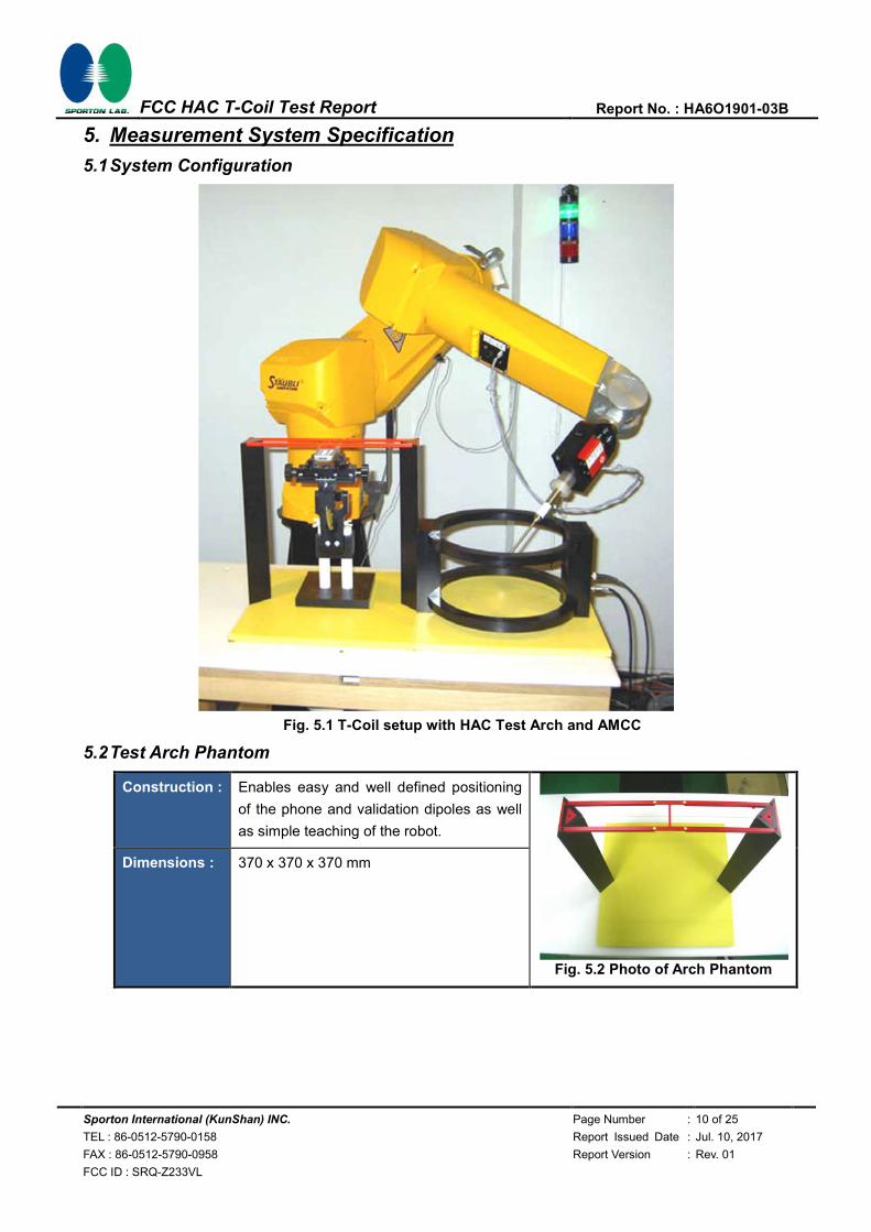
5.1 System Configuration
Fig. 5.1 T-Coil setup with HAC Test Arch and AMCC
5.2 Test Arch Phantom
Construction : Enables easy and well defined positioning
of the phone and validation dipoles as well
as simple teaching of the robot.
Fig. 5.2 Photo of Arch Phantom
Dimensions : 370 x 370 x 370 mm

Sporton International (KunShan) INC. Page Number : 11 of 25
TEL : 86-0512-5790-0158 Report Issued Date : Jul. 10, 2017
FAX : 86-0512-5790-0958 Report Version : Rev. 01
FCC ID : SRQ-Z233VL
FCC HAC T-Coil Test Report Report No. : HA6O1901-03B
5.3 AMCC
The Audio Magnetic Calibration coil is a Helmholtz Coil designed for calibration of the AM1D probe. The
two horizontal coils generate a homogeneous magnetic field in the z direction. The DC input resistance is
adjusted by a series resistor to approximately 50Ohm, and a shunt resistor of 10 Ohm permits monitoring
the current with a scale of 1:10.
Port description
Signal Connector Resistance
Coil In BNC typically 50 Ohm
Coil Monitor BNO 10Ohm ±1%(100mV corresponding to 1 A/m)
Specification
Dimensions 370 x 370 x 196 mm, according to ANSI C63.19
5.4 AM1D Probe
The AM1D probe is an active probe with a single sensor. It is fully RF-shielded and has a rounded tip
6mm in diameter incorporating a pickup coil with its center offset 3mm from the tip and the sides. The
symmetric signal preamplifier in the probe is fed via the shielded symmetric output cable from the AMMI
with a 48V “phantom” voltage supply. The 7-pin connector on the back in the axis of the probe does not
carry any signals. It is mounted to the DAE for the correct orientation of the sensor. If the probe axis is
tilted 54.7 degree from the vertical, the sensor is approximately vertical when the signal connector is at
the underside of the probe (cable hanging downwards).
Specification
Frequency Range 0.1 ~ 20 kHz (RF sensitivity <-100dB, fully RF shielded )
Sensitivity <-50dB A/m @ 1 kHz
Pre-amplifier 40 dB, symmetric
Dimensions Tip diameter/ length: 6/ 290 mm, sensor according to ANSI-C63.19
Sporton International (KunShan) INC. Page Number : 12 of 25
TEL : 86-0512-5790-0158 Report Issued Date : Jul. 10, 2017
FAX : 86-0512-5790-0958 Report Version : Rev. 01
FCC ID : SRQ-Z233VL
FCC HAC T-Coil Test Report Report No. : HA6O1901-03B
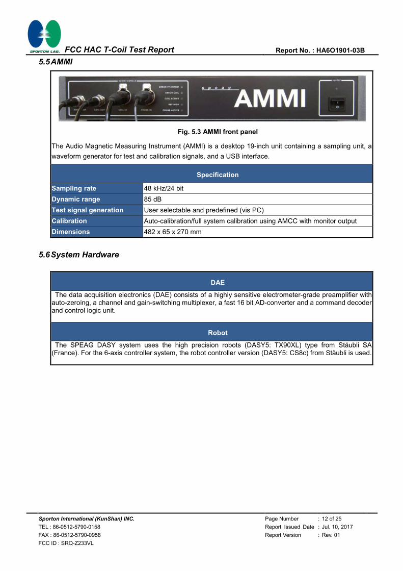
5.5 AMMI
Fig. 5.3 AMMI front panel
The Audio Magnetic Measuring Instrument (AMMI) is a desktop 19-inch unit containing a sampling unit, a
waveform generator for test and calibration signals, and a USB interface.
Specification
Sampling rate 48 kHz/24 bit
Dynamic range 85 dB
Test signal generation User selectable and predefined (vis PC)
Calibration Auto-calibration/full system calibration using AMCC with monitor output
Dimensions 482 x 65 x 270 mm
5.6 System Hardware
DAE
The data acquisition electronics (DAE) consists of a highly sensitive electrometer-grade preamplifier with auto-zeroing, a channel and gain-switching multiplexer, a fast 16 bit AD-converter and a command decoder and control logic unit.
Robot
The SPEAG DASY system uses the high precision robots (DASY5: TX90XL) type from Stäubli SA (France). For the 6-axis controller system, the robot controller version (DASY5: CS8c) from Stäubli is used.

Sporton International (KunShan) INC. Page Number : 13 of 25
TEL : 86-0512-5790-0158 Report Issued Date : Jul. 10, 2017
FAX : 86-0512-5790-0958 Report Version : Rev. 01
FCC ID : SRQ-Z233VL
FCC HAC T-Coil Test Report Report No. : HA6O1901-03B
5.7 Cabling of System for GSM / UMTS / CDMA
The principal cabling of the T-Coil setup is shown in Fig. 5.4 All cables provided with the basic setup have a
length of approximately 5 m.
Fig. 5.4 T-Coil setup cabling
5.8 Cabling of System for VoLTE
The principal cabling of the T-Coil setup is shown in Fig. 5.5 All cables provided with the basic setup have a
length of approximately 5 m.
Fig. 5.5 T-Coil setup cabling

Sporton International (KunShan) INC. Page Number : 14 of 25
TEL : 86-0512-5790-0158 Report Issued Date : Jul. 10, 2017
FAX : 86-0512-5790-0958 Report Version : Rev. 01
FCC ID : SRQ-Z233VL
FCC HAC T-Coil Test Report Report No. : HA6O1901-03B
5.9 Test Equipment List
Manufacturer Name of Equipment Type/Model Serial
Number
Calibration
Last Cal. Due Date
SPEAG Data Acquisition Electronics DAE4 1279 2017/5/2 2018/5/1
SPEAG Active Audio Magnetic Field Probe AM1DV3 3093 2017/5/19 2018/5/18
SPEAG Test Arch Phantom Par phantom 1105 NCR NCR
SPEAG Phone Positioner N/A N/A NCR NCR
R&S Universal Radio Communication Tester CMU500 150792 2017/1/19 2018/1/18
SPEAG Audio Magnetic Measuring Instrument AMMI 1128 NA NA
SPEAG Helmholtz calibration coil AMCC NA NA NA
Table 5.1 Test Equipment List Note: NCR: “No-Calibration Required”

Sporton International (KunShan) INC. Page Number : 15 of 25
TEL : 86-0512-5790-0158 Report Issued Date : Jul. 10, 2017
FAX : 86-0512-5790-0958 Report Version : Rev. 01
FCC ID : SRQ-Z233VL
FCC HAC T-Coil Test Report Report No. : HA6O1901-03B
5.10 Probe Calibration in AMCC
The probe sensitivity at 1 kHz is 0.06556 V/(A/m) (-23.66 dBV/(A/m)) was calibrated by AMCC coil for
verification of setup performance.
The evaluated probe sensitivity was able to be compared to the calibration of the AM1D probe. The
frequency response and sensitivity was shown in Fig. 5.5. The probe signal is represented after application
of an ideal integrator. The green curve represents the current though the AMCC, the blue curve the
integrated probe signal. The DIFFERENCE between the two curves is equivalent to the frequency response
of the probe system and shows the characteristics. The probe/system complies with the frequency
response and linearity requirements in C63.19 according to the SPEAG’s calibrated report as shown in
Annex B (AM1D probe: SPAM100AF) (1)The frequency response has been tested within +/- 0.5 dB of ideal
differentiator from 100 Hz to 10 kHz. (2)The linearity has also been tested within 0.1dB from 5 dB below
limitation to 16 dB above noise level. The AMCC coil is qualified according to certificate report,
SDHACPO02A as shown in Annex B.
Fig. 5.5 The frequency response and sensitivity of AM1D probe

Sporton International (KunShan) INC. Page Number : 16 of 25
TEL : 86-0512-5790-0158 Report Issued Date : Jul. 10, 2017
FAX : 86-0512-5790-0958 Report Version : Rev. 01
FCC ID : SRQ-Z233VL
FCC HAC T-Coil Test Report Report No. : HA6O1901-03B
5.11 Reference Input of Audio Signal Spectrum
With the reference job "use as reference" in the beginning of a procedure, measure the spectrum of the
current when applied to the AMCC, i.e. the input magnetic field spectrum, as shown below Fig. 5.6 and
Fig. 5.7. For this, the delay of the window shall be set to a multiple of the signal period and at least 2s.
From the measurement on the device, using the same signal, the postprocessor deducts the input
spectrum, so the result represents the net EUT response.
Fig. 5.6 Audio signal spectrum of the broadband signal (48kHz_voice_300Hz~3 kHz)
Fig. 5.7 Audio signal spectrum of the narrowband signal (48kHz_voice_1kHz)

Sporton International (KunShan) INC. Page Number : 17 of 25
TEL : 86-0512-5790-0158 Report Issued Date : Jul. 10, 2017
FAX : 86-0512-5790-0958 Report Version : Rev. 01
FCC ID : SRQ-Z233VL
FCC HAC T-Coil Test Report Report No. : HA6O1901-03B
5.12 Establish Reference Level for VoLTE
The normal speech input level -16dBm0 is used for VoLTE T-coil performance evaluation. The CMW500 base
station simulator was manually configured to ensure that the settings for speech input full scale levels resulted
in the -16dBm0 speech input level to the DUT for the VoLTE connection.
LTE Calculations: 3.14 dBm0 = -3.01 dBV -16 dBm0 = -25.07dBV Gain 10 = -20.02dBV -25.07 - (-20.02) = -5.05dB 10* [10 ^ ((-5.05) / 20)] = 10 x 0.559= 5.59 Required Gain Factor = 10^(-RMS(dB)/20) Gain Setting = Required Gain Factor * 5.59
Note: Calculated Gain Setting = Resulting Gain * Required Gain Factor According to the gain setting for 1kHz sine wave, determine the gain setting for signals below
Signal Type Duration
(s) Peak to
RMS (dB) RMS (dB)
Required Gain
Factor(1)
Calculated Gain Setting
Adjusted Gain
Setting(2)
48k_voice_1kHz 1 16.2 -12.7 4.33 24.21 24.21
48k_voice_300Hz ~ 3kHz 2 21.6 -18.6 8.48 47.41 47.41
Remark:
(1) The gain for the specific signal shall typically be multiplied by this factor to achieve approx. the same level as for the
1kHz sine signal.
(2) If the measurement for each signal type with calculated gain setting does not meet the desired level, the gain
setting will be manually adjusted until the desired level is obtained.

Sporton International (KunShan) INC. Page Number : 18 of 25
TEL : 86-0512-5790-0158 Report Issued Date : Jul. 10, 2017
FAX : 86-0512-5790-0958 Report Version : Rev. 01
FCC ID : SRQ-Z233VL
FCC HAC T-Coil Test Report Report No. : HA6O1901-03B
6. T-Coil Test Procedure
6.1 Test Process and Flow Chart
Referenced to ANSI C63.19-2011, Section 7.4
This section describes the procedures used to measure the ABM (T-Coil) performance of the WD. In
addition to measuring the absolute signal levels, the A-weighted magnitude of the unintended signal shall
also be determined. To assure that the required signal quality is measured, the measurement of the
intended signal and the measurement of the unintended signal must be made at the same location for
each measurement position. In addition, the RF field strength at each measurement location must be at or
below that required for the assigned category.
Measurements shall not include undesired properties from the WD's RF field; therefore, use of a coaxial
connection to a base station simulator or non-radiating load, there might still be RF leakage from the WD,
which can interfere with the desired measurement. Pre-measurement checks should be made to avoid
this possibility. All measurements shall be performed with the WD operating on battery power with an
appropriate normal speech audio signal input level given in ANSI C63.19-2011 Table 7.1. If the device
display can be turned off during a phone call, then that may be done during the measurement as well,
Measurement shall be performed at two locations specified in ANSI C63.19-2011 A.3, with the correct
probe orientation for a particular location, in a multistage sequence by first measuring the field intensity of
the desired T-Coil signal the same location as the desired ABM or T-Coil signal (ABM1), and the ratio of
desired to undesired magnetic components (ABM2) must be measured at the same location as the
desired ABM or T-Coil signal (ABM1), and the ratio of desired to undesired ABM signals must be
calculated. For the perpendicular field location, only the ABM1 frequency response shall be determined in
a third measurement stage.
The following steps summarize the basic test flow for determining ABM1 and ABM2. These steps assume
that a sine wave or narrowband 1/3 octave signal can be used for the measurement of ABM1.
a) A validation of the test setup and instrumentation may be performed using a TMFS or Helmholtz coil
Measure the emissions and confirm that they are within the specified tolerance.
b) Position the WD in the test setup and connect the WD RF connector to a base station simulator or a
non-radiating load. Confirm that equipment that requires calibration has been calibrated, and that
the noise level meets the requirements given in ANSI C63.19-2011 clause 7.3.1.
c) The drive level to the WD ise set such that the reference input level specified in ANSI C63.19-2011
Table 7.1 is input to the base station simulator (or manufacturer's test mode equivalent) in 1 kHz, 1/3
octave band. This drive level shall be used for the T-Coil signal test (ABM1) at f = 1 kHz. Either a
sine wave at 1025 Hz or a voice-like signal, band-limited to the 1 kHz 1/3 octave, as defined in ANSI
C63.19-2011 clause 7.4.2, shall be used for the reference audio signal. If interference is found at
1025 Hz an alternative nearby reference audio signal frequency may be used. The same drive level
shall be used for the ABM1 frequency response measurements at each 1/3 octave band center
frequency. The WD volume control may be set at any level up to maximum, provided that a signal at
any frequency at maximum modulation would not result in clipping or signal overload.

Sporton International (KunShan) INC. Page Number : 19 of 25
TEL : 86-0512-5790-0158 Report Issued Date : Jul. 10, 2017
FAX : 86-0512-5790-0958 Report Version : Rev. 01
FCC ID : SRQ-Z233VL
FCC HAC T-Coil Test Report Report No. : HA6O1901-03B
d) Determine the magnetic measurement locations for the WD device (A.3), if not already specified by
the manufacturer, as described in ANSI C63.19-2011 clause 7.4.4.1.1 and 7.4.4.2.
e) At each measurement location, measure and record the desired T-Coil magnetic signals (ABM1 at fi)
as described in ANSI C63.19-2011 clause 7.4.4.2 in each individual ISO 266-1975 R10 standard 1/3
octave band. The desired audio band input frequency (fi) shall be centered in each 1/3 octave band
maintaining the same drive level as determined in item c) and the reading taken for that band.
Equivalent methods of determining the frequency response may also be employed, such as fast
Fourier transform (FFT) analysis using noise excitation or input-output comparison using simulated
speech. The full-band integrated probe output, as specified in D.9, may be used, as long as the
appropriate calibration curve is applied to the measured result, so as to yield an accurate
measurement of the field magnitude. (The resulting measurement shall be an accurate
measurement in dB A/m.)
All Measurements of the desired signal shall be shown to be of the desired signal and not of an
undesired signal. This may be shown by turning the desired signal ON and OFF with the probe
measuring the same location. If the scanning method is used the scans shall show that all
measurement points selected for the ABM1 measurement meet the ambient and test system noise
criteria in ANSI C63.19-2011 clause 7.3.1.
f) At the measurement location for each orientation, measure and record the undesired broadband
audio magnetic signal (ABM2) as specified in ANSI C63.19-2011 clause 7.4.4.4 with no audio signal
applied (or digital zero applied, if appropriate) using A-weighting and the half-band integrator.
Calculate the ratio of the desired to undesired signal strength (i,e., signal quality).
g) Obtain the data from the postprocessor, SEMCAD, and determine the category that properly
classifies the signal quality based on ANSI C63.19-2011 Table 8.5.

Sporton International (KunShan) INC. Page Number : 20 of 25
TEL : 86-0512-5790-0158 Report Issued Date : Jul. 10, 2017
FAX : 86-0512-5790-0958 Report Version : Rev. 01
FCC ID : SRQ-Z233VL
FCC HAC T-Coil Test Report Report No. : HA6O1901-03B
Fig. 6.1 Test Flow Chart
Confirm calibration of test equipment Configure and validate the test setup Establish WD reference level Scan for measurement locations
Position and orient probe Measure desired audio band signal
Strength Measure undesired audio band signal
Strength
Calculate signal strength Calculate signal quality Measure frequency response
Determine and record signal quality category
Both y z locations measured?
Intensity and frequency response compliant ?
Y
Y
N
N
Done

Sporton International (KunShan) INC. Page Number : 21 of 25
TEL : 86-0512-5790-0158 Report Issued Date : Jul. 10, 2017
FAX : 86-0512-5790-0958 Report Version : Rev. 01
FCC ID : SRQ-Z233VL
FCC HAC T-Coil Test Report Report No. : HA6O1901-03B
6.2 Description of EUT Test Position
Fig.6.2 illustrate the references and reference plane that shall be used in a typical EUT emissions
measurement. The principle of this section is applied to EUT with similar geometry. Please refer to
Appendix C for the setup photographs.
The area is 5 cm by 5 cm.
The area is centered on the audio frequency output transducer of the EUT.
The area is in a reference plane, which is defined as the planar area that contains the highest point
in the area of the phone that normally rests against the user’s ear. It is parallel to the centerline of
the receiver area of the phone and is defined by the points of the receiver-end of the EUT handset,
which, in normal handset use, rest against the ear.
The measurement plane is parallel to, and 10 mm in front of, the reference plane.
Fig 6.2 A typical EUT reference and plane for T-Coil measurements

Sporton International (KunShan) INC. Page Number : 22 of 25
TEL : 86-0512-5790-0158 Report Issued Date : Jul. 10, 2017
FAX : 86-0512-5790-0958 Report Version : Rev. 01
FCC ID : SRQ-Z233VL
FCC HAC T-Coil Test Report Report No. : HA6O1901-03B
7. HAC T-Coil Test Results
7.1 Preliminary Scan for VoLTE T-coil performance
Step1: Frequency band, configure LTE in the highest power configuration (normally, it will be 1RB
configuration and QPSK modulation, MPR=0 dB), and test different codecs. The codec related to the worst
SNR will be used for following tests.
Step2: For all LTE bands, configure the uplink transmission in 1 RB and QPSK modulation. Test this code
identified in (1), for ABM1 level, SNR, frequency response for all frequency bands
<Step 1>
Air Interface Operating Mode Channel Probe
Position ABM1
(dB A/m) ABM2
(dB A/m) SNR (dB)
T Rating
LTE Band 2 20M_QPSK_1RB_0Offset_NB AMR 4.75Kbps 18900 Axial (Z) 3.48 -45.91 49.39 T4
LTE Band 2 20M_QPSK_1RB_0Offset_NB AMR 6.6Kbps 18900 Axial (Z) 2.26 -41.96 44.22 T4
LTE Band 2 20M_QPSK_1RB_0Offset_NB AMR 12.2Kbps 18900 Axial (Z) 7.04 -42.30 49.34 T4
LTE Band 2 20M_QPSK_1RB_0Offset_NB AMR 23.85Kbps 18900 Axial (Z) 5.04 -40.24 45.28 T4

Sporton International (KunShan) INC. Page Number : 23 of 25
TEL : 86-0512-5790-0158 Report Issued Date : Jul. 10, 2017
FAX : 86-0512-5790-0958 Report Version : Rev. 01
FCC ID : SRQ-Z233VL
FCC HAC T-Coil Test Report Report No. : HA6O1901-03B
7.2 Magnitude Result for VoLTE
Plot No.
Air Interface Operating Mode Channel Probe
Position ABM1
(dB A/m) ABM2
(dB A/m) SNR (dB)
T Rating
Frequency Response
1 LTE Band 2 20M_QPSK_1RB_0Offset
_6.6Kbps_Voice 18900
Axial (Z) 2.26 -41.96 44.22 T4 PASS
Transversal (Y) -4.58 -46.95 42.37 T4
2 LTE Band 4 20M_QPSK_1RB_0Offset
_6.6Kbps_Voice 20175
Axial (Z) 1.74 -41.38 43.12 T4 PASS
Transversal (Y) -5.62 -48.53 42.91 T4
3 LTE Band 13 10M_QPSK_1RB_0Offset
_6.6Kbps_Voice 23230
Axial (Z) 0.90 -44.71 45.61 T4 PASS
Transversal (Y) -4.20 -48.27 44.07 T4
Remark:
1. There is special HAC mode software on this EUT. 2. The detail frequency response results please refer to appendix A.
3. Test Engineer:Nick Hu

Sporton International (KunShan) INC. Page Number : 24 of 25
TEL : 86-0512-5790-0158 Report Issued Date : Jul. 10, 2017
FAX : 86-0512-5790-0958 Report Version : Rev. 01
FCC ID : SRQ-Z233VL
FCC HAC T-Coil Test Report Report No. : HA6O1901-03B
8. Uncertainty Assessment
The evaluation of uncertainly by the statistical analysis of a series of observations is termed a Type A evaluation of uncertainty. The evaluation of uncertainty by means other than the statistical analysis of a series of observation is termed a Type B evaluation of uncertainty. Each component of uncertainty, however evaluated, is represented by an estimated standard deviation, termed standard uncertainty, which is determined by the positive square root of the estimated variance. The combined standard uncertainty of the measurement result represents the estimated standard deviation of the result. It is obtained by combining the individual standard uncertainties of both Type A and Type B evaluation using the usual “root-sum-squares” (RSS) methods of combining standard deviations by taking the positive square root of the estimated variances. Expanded uncertainty is a measure of uncertainty that defines an interval about the measurement result within which the measured value is confidently believed to lie. It is obtained by multiplying the combined standard uncertainty by a coverage factor. For purpose of this document, a coverage factor two is used, which corresponds to confidence interval of about 95 %. The DASY uncertainty Budget is showed in Table 8.2.
Error Description Uncertainty
Value (±%)
Probability Distribution
Divisor Ci
(ABM1) Ci
(ABM2)
Standard Uncertainty
(ABM1)
Standard Uncertainty
(ABM2)
Probe Sensitivity
Reference Level 3.0 Normal 1 1 1 ± 3.0 % ± 3.0 %
AMCC Geometry 0.4 Rectangular √3 1 1 ± 0.2 % ± 0.2 %
AMCC Current 1.0 Rectangular √3 1 1 ± 0.6 % ± 0.6 %
Probe Positioning During Calibrate
0.1 Rectangular √3 1 1 ± 0.1 % ± 0.1 %
Noise Contribution 0.7 Rectangular √3 0.0143 1 ± 0.0 % ± 0.4 %
Frequency Slope 5.9 Rectangular √3 0.1 1 ± 0.3 % ± 3.5 %
Probe System
Repeatability / Drift 1.0 Rectangular √3 1 1 ± 0.6 % ± 0.6 %
Linearity / Dynamic Range 0.6 Rectangular √3 1 1 ± 0.4 % ± 0.4 %
Acoustic Noise 1.0 Rectangular √3 0.1 1 ± 0.1 % ± 0.6 %
Probe Angle 2.3 Rectangular √3 1 1 ± 1.4 % ± 1.4 %
Spectral Processing 0.9 Rectangular √3 1 1 ± 0.5 % ± 0.5 %
Integration Time 0.6 Normal 1 1 5 ± 0.6 % ± 3.0 %
Field Disturbation 0.2 Rectangular √3 1 1 ± 0.1 % ± 0.1 %
Test Signal
Reference Signal Spectral Response
0.6 Rectangular √3 0 1 ± 0.0 % ± 0.4 %
Positioning
Probe Positioning 1.9 Rectangular √3 1 1 ± 1.1 % ± 1.1 %
Phantom Thickness 0.9 Rectangular √3 1 1 ± 0.5 % ± 0.5 %
EUT Positioning 1.9 Rectangular √3 1 1 ± 1.1 % ± 1.1 %
External Contributions
RF Interference 0.0 Rectangular √3 1 0.3 ± 0.0 % ± 0.0 %
Test Signal Variation 2.0 Rectangular √3 1 1 ± 1.2 % ± 1.2 %
Combined Standard Uncertainty ± 4.1 % ± 6.1 %
Coverage Factor for 95 % K = 2
Expanded Uncertainty ± 8.1 % ± 12.3 %
Table 8.1 Uncertainty Budget of audio band magnetic measurement

Sporton International (KunShan) INC. Page Number : 25 of 25
TEL : 86-0512-5790-0158 Report Issued Date : Jul. 10, 2017
FAX : 86-0512-5790-0958 Report Version : Rev. 01
FCC ID : SRQ-Z233VL
FCC HAC T-Coil Test Report Report No. : HA6O1901-03B
9. References
[1] ANSI C63.19-2011, “American National Standard for Methods of Measurement of Compatibility
between Wireless Communications Devices and Hearing Aids”, 27 May 2011.
[2] FCC KDB 285076 D01v04r01, “Equipment Authorization Guidance for Hearing Aid Compatibility”, Apr
2016
[3] FCC KDB 285076 D02v02, “Guidance for Performing T-Coil tests for Air Interfaces Supporting Voice
over IP”, Apr 2016
[4] SPEAG DASY System Handbook
Sporton International (KunShan) INC. Page Number : A1 of A1
TEL : 86-0512-5790-0158 Report Issued Date : Jul. 10, 2017
FAX : 86-0512-5790-0958 Report Version : Rev. 01
FCC ID : SRQ-Z233VL
FCC HAC T-Coil Test Report Report No. : HA6O1901-03B
Appendix A. Plots of T-Coil Measurement
The plots are shown as follows.

Test Laboratory: Sporton International Inc. SAR/HAC Testing Lab Date: 2017.7.6
01_HAC_T-Coil_LTE Band 2_20M_QPSK_1RB_0offset_NB AMR6.6Kbps_Ch18900(Z)
Communication System: UID 0, FDD_LTE (0); Frequency: 1880 MHz;Duty Cycle: 1:1 Medium: Air Medium parameters used: σ = 0 S/m, εr = 1; ρ = 0 kg/m3
Ambient Temperature:23.5 ℃
DASY5 Configuration:- Probe: AM1DV3 - 3093; ; Calibrated: 2017.5.19- Sensor-Surface: 0mm (Fix Surface)- Electronics: DAE4 Sn1279; Calibrated: 2017.5.2- Phantom: HAC Test Arch with AMCC; Type: SD HAC P01 BA;- Measurement SW: DASY52, Version 52.8 (8); SEMCAD X Version 14.6.10 (7331)
General Scans/z (axial) 4.2mm 50 x 50/ABM SNR(x,y,z) (13x13x1): Measurement grid: dx=10mm, dy=10mm ABM1/ABM2 = 44.22 dB ABM1 comp = 2.26 dBA/m Location: 0, 4.2, 3.7 mm
0 dB = 1.00 dB


Test Laboratory: Sporton International Inc. SAR/HAC Testing Lab Date: 2017.7.6
01_HAC_T-Coil_LTE Band 2_20M_QPSK_1RB_0offset_NB AMR6.6Kbps_Ch18900(Y)
Communication System: UID 0, FDD_LTE (0); Frequency: 1880 MHz;Duty Cycle: 1:1 Medium: Air Medium parameters used: σ = 0 S/m, εr = 1; ρ = 0 kg/m3
Ambient Temperature:23.5 ℃
DASY5 Configuration:- Probe: AM1DV3 - 3093; ; Calibrated: 2017.5.19- Sensor-Surface: 0mm (Fix Surface)- Electronics: DAE4 Sn1279; Calibrated: 2017.5.2- Phantom: HAC Test Arch with AMCC; Type: SD HAC P01 BA;- Measurement SW: DASY52, Version 52.8 (8); SEMCAD X Version 14.6.10 (7331)
General Scans/y (transversal) 4.2mm 50 x 50/ABM SNR(x,y,z) (13x13x1): Measurement grid: dx=10mm, dy=10mm ABM1/ABM2 = 42.37 dB ABM1 comp = -4.58 dBA/m Location: 0, 8.3, 3.7 mm
0 dB = 1.000 A/m = 0.00 dBA/m

Test Laboratory: Sporton International Inc. SAR/HAC Testing Lab Date: 2017.7.6
02_HAC_T-Coil_LTE Band 4_20M_QPSK_1RB_0offset_NB AMR6.6Kbps_Ch20175(Z)
Communication System: UID 0, FDD_LTE (0); Frequency: 1732.5 MHz;Duty Cycle: 1:1 Medium: Air Medium parameters used: σ = 0 S/m, εr = 1; ρ = 0 kg/m3
Ambient Temperature:23.5 ℃
DASY5 Configuration:- Probe: AM1DV3 - 3093; ; Calibrated: 2017.5.19- Sensor-Surface: 0mm (Fix Surface)- Electronics: DAE4 Sn1279; Calibrated: 2017.5.2- Phantom: HAC Test Arch with AMCC; Type: SD HAC P01 BA;- Measurement SW: DASY52, Version 52.8 (8); SEMCAD X Version 14.6.10 (7331)
General Scans/z (axial) 4.2mm 50 x 50/ABM SNR(x,y,z) (13x13x1): Measurement grid: dx=10mm, dy=10mm ABM1/ABM2 = 43.12 dB ABM1 comp = 1.74 dBA/m Location: 0, 4.2, 3.7 mm
0 dB = 1.00 dB


Test Laboratory: Sporton International Inc. SAR/HAC Testing Lab Date: 2017.7.6
02_HAC_T-Coil_LTE Band 4_20M_QPSK_1RB_0offset_NB AMR6.6Kbps_Ch20175(Y)
Communication System: UID 0, FDD_LTE (0); Frequency: 1732.5 MHz;Duty Cycle: 1:1 Medium: Air Medium parameters used: σ = 0 S/m, εr = 1; ρ = 0 kg/m3
Ambient Temperature:23.5 ℃
DASY5 Configuration:- Probe: AM1DV3 - 3093; ; Calibrated: 2017.5.19- Sensor-Surface: 0mm (Fix Surface)- Electronics: DAE4 Sn1279; Calibrated: 2017.5.2- Phantom: HAC Test Arch with AMCC; Type: SD HAC P01 BA;- Measurement SW: DASY52, Version 52.8 (8); SEMCAD X Version 14.6.10 (7331)
General Scans/y (transversal) 4.2mm 50 x 50/ABM SNR(x,y,z) (13x13x1): Measurement grid: dx=10mm, dy=10mm ABM1/ABM2 = 42.91 dB ABM1 comp = -5.62 dBA/m Location: 0, 8.3, 3.7 mm
0 dB = 1.000 A/m = 0.00 dBA/m

Test Laboratory: Sporton International Inc. SAR/HAC Testing Lab Date: 2017.7.6
03_HAC_T-Coil_LTE Band 13_10M_QPSK_1RB_0offset_NB AMR6.6Kbps_Ch23230(Z)
Communication System: UID 0, FDD_LTE (0); Frequency: 782 MHz;Duty Cycle: 1:1
Medium: Air Medium parameters used: σ = 0 S/m, εr = 1; ρ = 0 kg/m3
Ambient Temperature:23.5 ℃
DASY5 Configuration:- Probe: AM1DV3 - 3093; ; Calibrated: 2017.5.19- Sensor-Surface: 0mm (Fix Surface)- Electronics: DAE4 Sn1279; Calibrated: 2017.5.2- Phantom: HAC Test Arch with AMCC; Type: SD HAC P01 BA;- Measurement SW: DASY52, Version 52.8 (8); SEMCAD X Version 14.6.10 (7331)
General Scans/z (axial) 4.2mm 50 x 50/ABM SNR(x,y,z) (13x13x1): Measurement grid: dx=10mm, dy=10mm ABM1/ABM2 = 45.61 dB ABM1 comp = 0.90 dBA/m Location: 4.2, 4.2, 3.7 mm
0 dB = 1.00 dB


Test Laboratory: Sporton International Inc. SAR/HAC Testing Lab Date: 2017.7.6
03_HAC_T-Coil_LTE Band 13_10M_QPSK_1RB_0offset_NB AMR6.6Kbps_Ch23230(Y)
Communication System: UID 0, FDD_LTE (0); Frequency: 782 MHz;Duty Cycle: 1:1
Medium: Air Medium parameters used: σ = 0 S/m, εr = 1; ρ = 0 kg/m3
Ambient Temperature:23.5 ℃
DASY5 Configuration:- Probe: AM1DV3 - 3093; ; Calibrated: 2017.5.19- Sensor-Surface: 0mm (Fix Surface)- Electronics: DAE4 Sn1279; Calibrated: 2017.5.2- Phantom: HAC Test Arch with AMCC; Type: SD HAC P01 BA;- Measurement SW: DASY52, Version 52.8 (8); SEMCAD X Version 14.6.10 (7331)
General Scans/y (transversal) 4.2mm 50 x 50/ABM SNR(x,y,z) (13x13x1): Measurement grid: dx=10mm, dy=10mm ABM1/ABM2 = 44.07 dB ABM1 comp = -4.20 dBA/m Location: 0, -8.3, 3.7 mm
0 dB = 1.000 A/m = 0.00 dBA/m

Sporton International (KunShan) INC. Page Number : B1 of B1
TEL : 86-0512-5790-0158 Report Issued Date : Jul. 10, 2017
FAX : 86-0512-5790-0958 Report Version : Rev. 01
FCC ID : SRQ-Z233VL
FCC HAC T-Coil Test Report Report No. : HA6O1901-03B
Appendix B. Calibration Data
The DASY calibration certificates are shown as follows.


Sporton International (KunShan) INC. Page Number : D1 of D1
TEL : 86-0512-5790-0158 Report Issued Date : Jul. 10, 2017
FAX : 86-0512-5790-0958 Report Version : Rev. 01
FCC ID : SRQ-Z233VL
FCC HAC T-Coil Test Report Report No. : HA6O1901-03B
Appendix D. Product Equality Declaration

内部公开 Internal Use Only▲
<以上所有信息均为中兴通讯股份有限公司所有,不得外传> All Rights reserved, No Spreading abroad without Permission of ZTE
第 1 页
ZTE CORPORATION
Product Change Description
As the applicant of the below model, [ZTE Corporation] declares that the
product,
[Z233V]
[ZTE Corporation]
is the variant of the initial certified product,
[Z233VL]
[ZTE Corporation]
[Project Number: 16ZTE410]
FCC ID: SRQ-Z233VL
SOFTWARE MODIFICATIONS:
Protocol Stack changes: NO
MMS/STK changes: NO
JAVA changes: NO
Other changes detailed: Yes, FOTA feature updated.
HARDWARE MODIFICATION:
Band changes: NO
Power Amplifier changes: NO
Antenna changes: NO
PCB Layout changes: NO
Components on PCB changes: YES,new chipset on WIFI/BT/FM(3 in 1) and
Bluetooth/WLAN filter. But Z233V do not support WIFI-disabled via software. No
function changed, no Bluetooth RF/Pro spec changed.
Additional information:
The new chip component is pin-for-pin compatible.

内部公开 Internal Use Only▲
<以上所有信息均为中兴通讯股份有限公司所有,不得外传> All Rights reserved, No Spreading abroad without Permission of ZTE
第 2 页
The new chip has the same basic function as the old chip,
No change in radio parameters has occurred.
LCD changes: NO
Speaker changes: NO
Camera changes: NO
Vibrator changes: NO
Bluetooth changes: YES, new chipset
FM changes: NO
Other changes: NO
MECHANICAL MODIFICATIONS:
Use new metal front/back cover or keypad: NO
Mechanical shell changes: YES,new silk screen
Other changes detailed: NO
ACCESSORY MODIFICATIONS:
Battery changes: NO
AC Adaptor changes: YES
Original Adaptor information:
Dokocom - STC-A508A-Z,STC-A508A-Z M5 - Revision: A
Ruijing - STC-A508A-Z,STC-A508A-Z M5 - Revision: A
New Adaptor information:
Dokocom - STC-A508A-Z,STC-A508A-Z M5 - Revision: A1
Ruijing - STC-A508A-Z,STC-A508A-Z M5 - Revision: A1
Chenyang - STC-A508A-Z - Revision: A
Earphone changes: NO
APPROVED BY: Min Zhang
Project Manager: Li zhiqiang
Date:2017-6-2
Company: ZTE Corporation
Address: B109, #889, Bibo Rd, Zhangjiang Hi-Tech Park, Shanghai, China
Tel:+86-21-68896840
Fax: +86-21-68896835