heartland pergola
TRANSCRIPT
Assembly Manual
HeartlandPergola
Thank you for your purchase of this Pergola
This manual is designed to simplify the assembly process, however we recommend having an experienced carpenter involved in the project. Please read through the entire manual before starting!
The Pergola put together for this manual was a 12 X 15 Rectangle. This manual can also be used for other sizes. It took 2 men, approximately 3 hours using the tools shown below. However, it may take you longer since it will be a new project for you.
Take a deep breath and get at it; the satisfaction and enjoyment of this pergola is only a few hours away. Have fun!
You have purchased a product that consists of heavy, bulky pieces. With your purchase, you assume full responsibility to have the necessary manpower and/or equipment available to unload the items. You also agree that any damage that happens to the equipment, product, or individuals during the unloading process, or during the entire construction process, is your responsibility , and neither the seller, nor the manufacturer, will be held liable for any such damage.
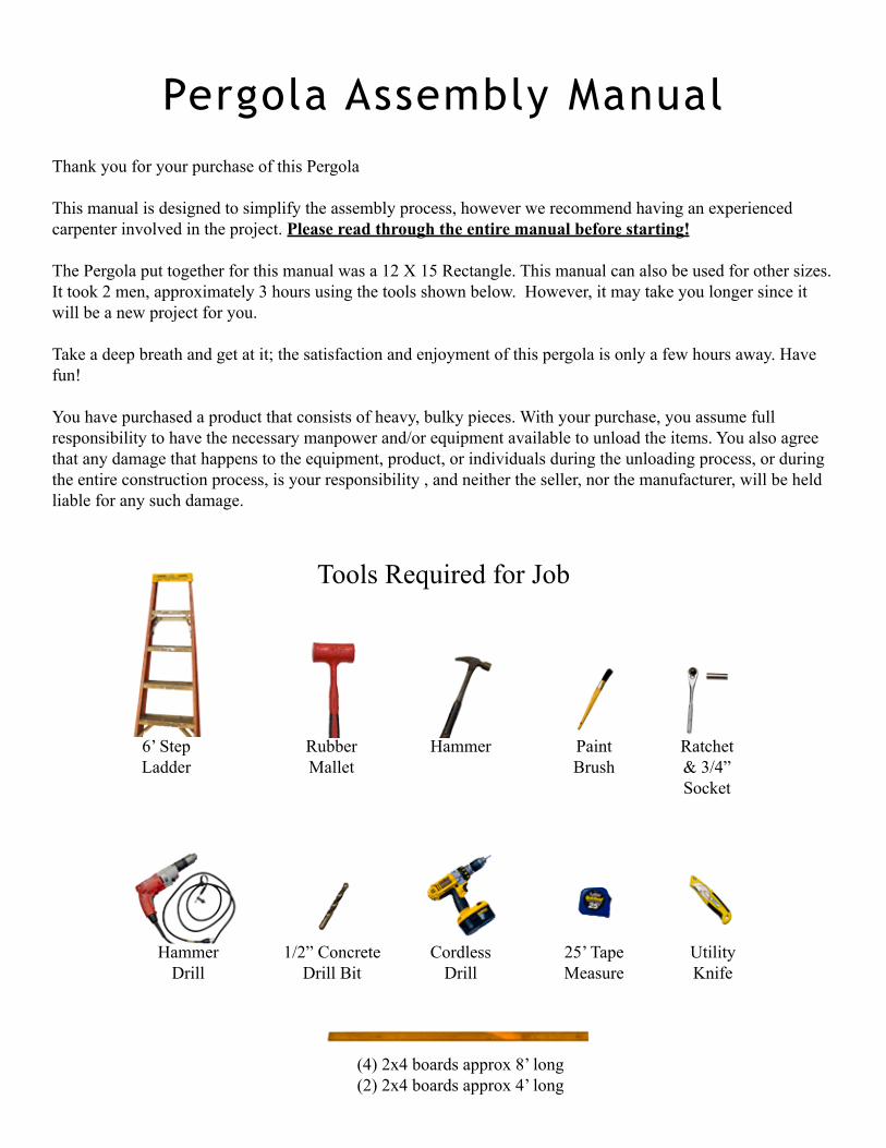
Pergola Assembly Manual
Tools Required for Job
6’ Step Ladder
RubberMallet
Hammer PaintBrush
Ratchet& 3/4” Socket
HammerDrill
1/2” Concrete Drill Bit
CordlessDrill
25’ TapeMeasure
Utility Knife
(4) 2x4 boards approx 8’ long(2) 2x4 boards approx 4’ long
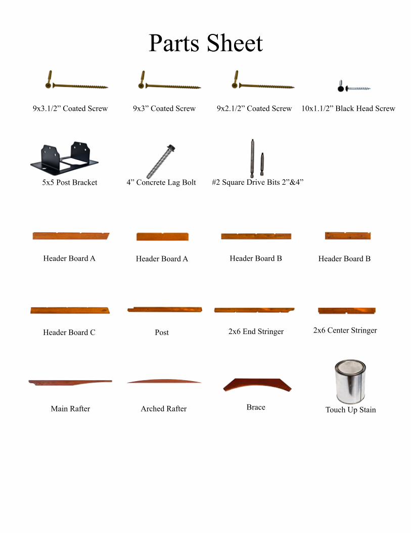
#2 Square Drive Bits 2”&4”
9x3” Coated Screw9x3.1/2” Coated Screw 9x2.1/2” Coated Screw 10x1.1/2” Black Head Screw
5x5 Post Bracket 4” Concrete Lag Bolt
Touch Up Stain
Header Board C
Header Board B Header Board BHeader Board A Header Board A
Post
BraceMain Rafter
2x6 End Stringer 2x6 Center Stringer
Parts Sheet
Arched Rafter
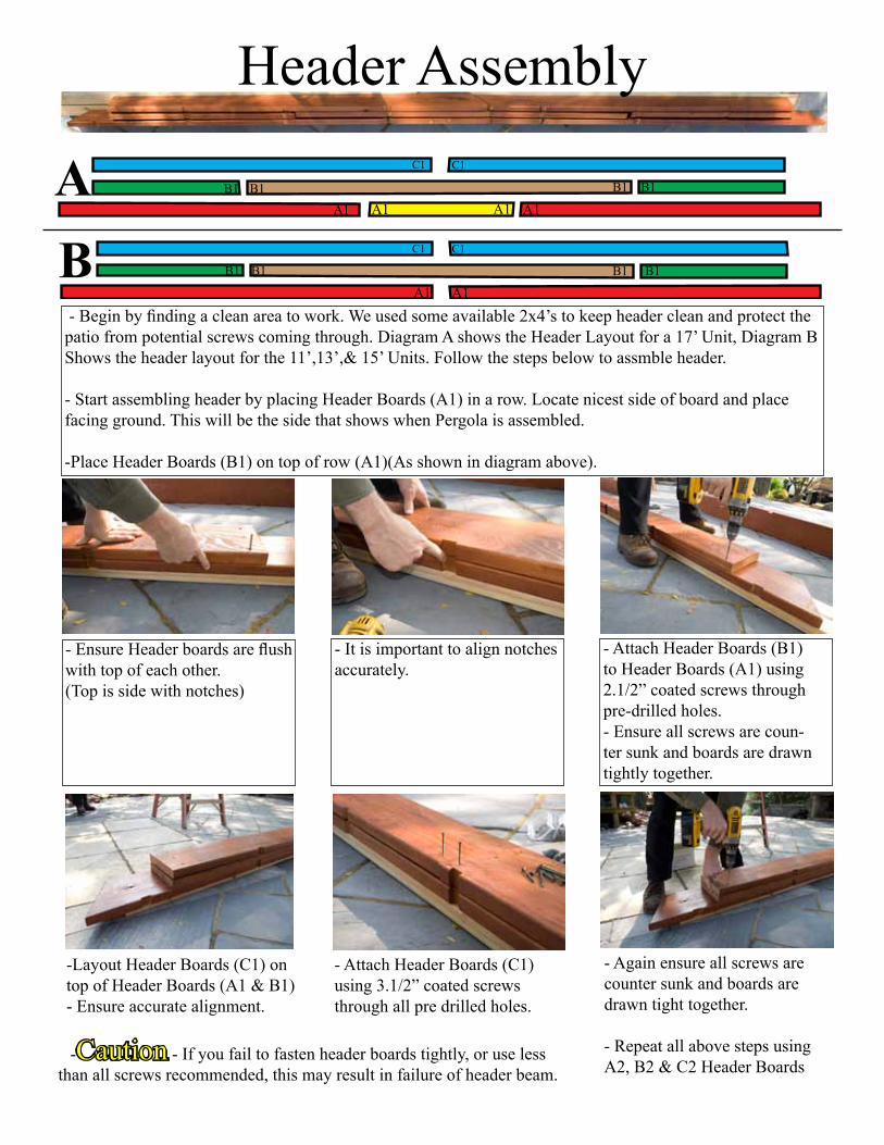
Header Assembly
- Begin by finding a clean area to work. We used some available 2x4’s to keep header clean and protect the patio from potential screws coming through. Diagram A shows the Header Layout for a 17’ Unit, Diagram B Shows the header layout for the 11’,13’,& 15’ Units. Follow the steps below to assmble header.
- Start assembling header by placing Header Boards (A1) in a row. Locate nicest side of board and place facing ground. This will be the side that shows when Pergola is assembled.
-Place Header Boards (B1) on top of row (A1)(As shown in diagram above).
- It is important to align notches accurately.
A1 A1 A1 A1B1 B1 B1 B1
C1C1
- Ensure Header boards are flush with top of each other. (Top is side with notches)
- Attach Header Boards (B1) to Header Boards (A1) using 2.1/2” coated screws through pre-drilled holes.- Ensure all screws are coun-ter sunk and boards are drawn tightly together.
- Attach Header Boards (C1) using 3.1/2” coated screws through all pre drilled holes.
-Layout Header Boards (C1) on top of Header Boards (A1 & B1) - Ensure accurate alignment.
- Again ensure all screws are counter sunk and boards are drawn tight together.
- Repeat all above steps using A2, B2 & C2 Header Boards
-Caution - If you fail to fasten header boards tightly, or use less than all screws recommended, this may result in failure of header beam.
AB
A1 A1B1 B1 B1 B1
C1C1
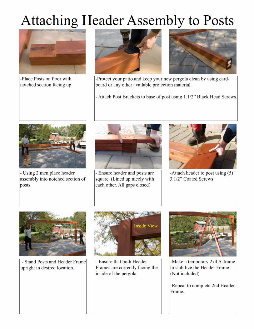
Attaching Header Assembly to Posts
-Protect your patio and keep your new pergola clean by using card-board or any other available protection material.
- Attach Post Brackets to base of post using 1.1/2” Black Head Screws.
-Place Posts on floor with notched section facing up
- Ensure header and posts are square. (Lined up nicely with each other. All gaps closed)
- Using 2 men place header assembly into notched section of posts.
- Stand Posts and Header Frame upright in desired location.
-Make a temporary 2x4 A-frame to stabilize the Header Frame. (Not included)
-Repeat to complete 2nd Header Frame.
- Ensure that both Header Frames are correctly facing the inside of the pergola.
Inside View
-Attach header to post using (5) 3.1/2” Coated Screws
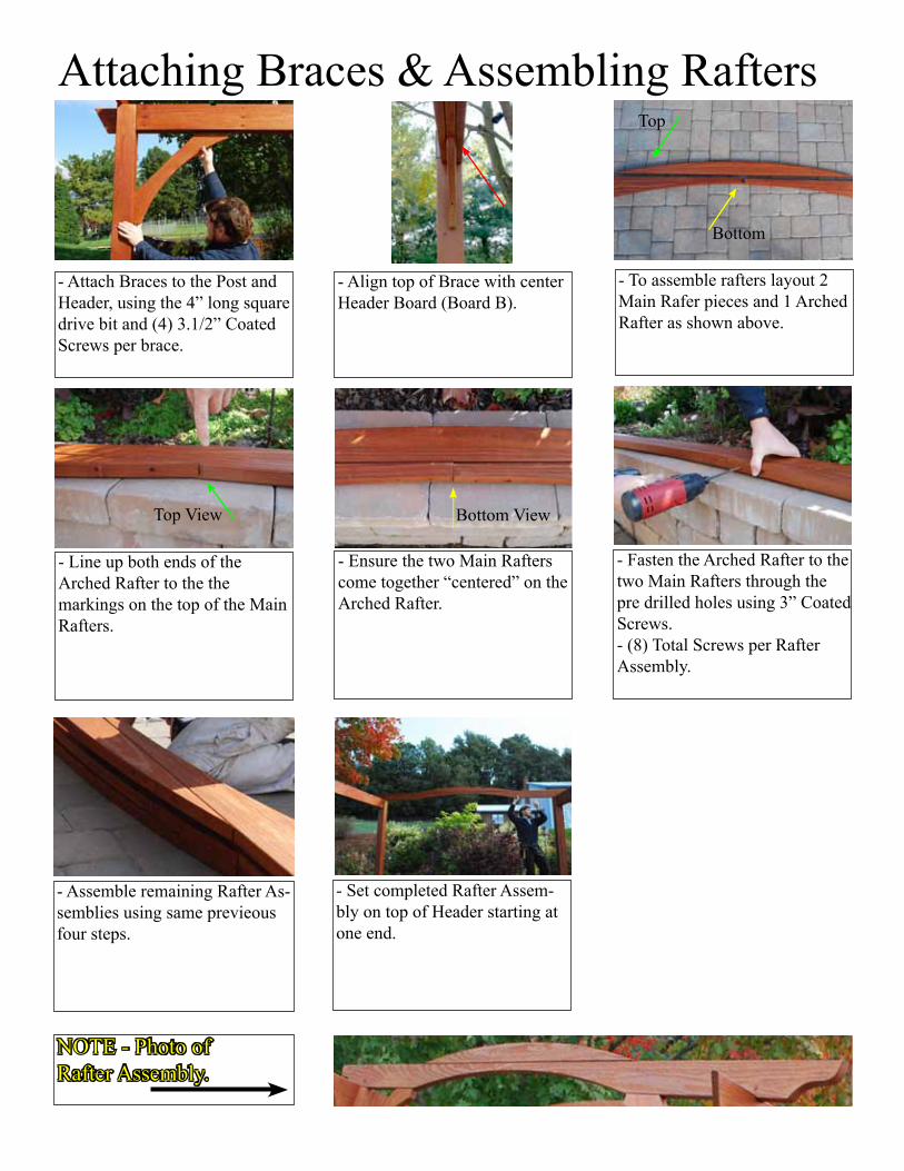
Attaching Braces & Assembling Rafters
- Align top of Brace with center Header Board (Board B).
- Attach Braces to the Post and Header, using the 4” long square drive bit and (4) 3.1/2” Coated Screws per brace.
- Line up both ends of the Arched Rafter to the the markings on the top of the Main Rafters.
- To assemble rafters layout 2 Main Rafer pieces and 1 Arched Rafter as shown above.
- Ensure the two Main Rafters come together “centered” on the Arched Rafter.
- Fasten the Arched Rafter to the two Main Rafters through the pre drilled holes using 3” Coated Screws.- (8) Total Screws per Rafter Assembly.
- Assemble remaining Rafter As-semblies using same previeous four steps.
- Set completed Rafter Assem-bly on top of Header starting at one end.
NOTE - Photo ofRafter Assembly.
Top
Bottom
Top View Bottom View
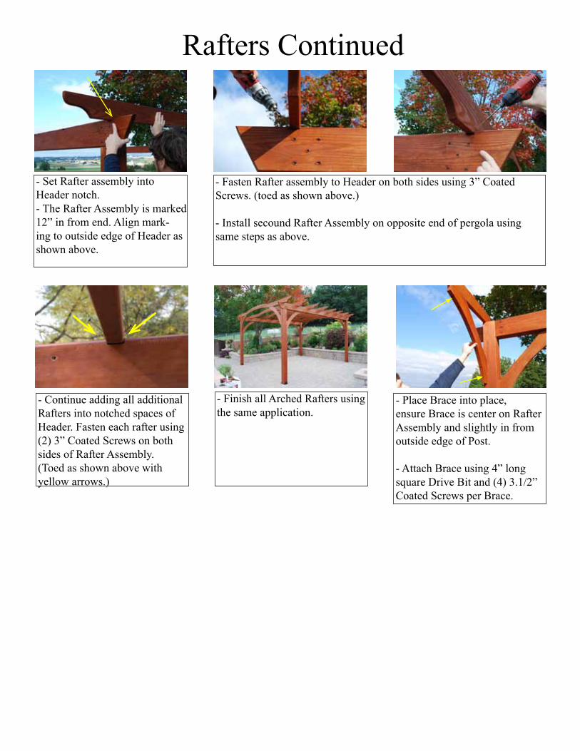
- Place Brace into place,ensure Brace is center on Rafter Assembly and slightly in from outside edge of Post.
- Attach Brace using 4” long square Drive Bit and (4) 3.1/2” Coated Screws per Brace.
- Set Rafter assembly into Header notch.- The Rafter Assembly is marked 12” in from end. Align mark-ing to outside edge of Header as shown above.
- Continue adding all additional Rafters into notched spaces of Header. Fasten each rafter using (2) 3” Coated Screws on both sides of Rafter Assembly. (Toed as shown above with yellow arrows.)
- Fasten Rafter assembly to Header on both sides using 3” Coated Screws. (toed as shown above.)
- Install secound Rafter Assembly on opposite end of pergola using same steps as above.
- Finish all Arched Rafters using the same application.
Rafters Continued
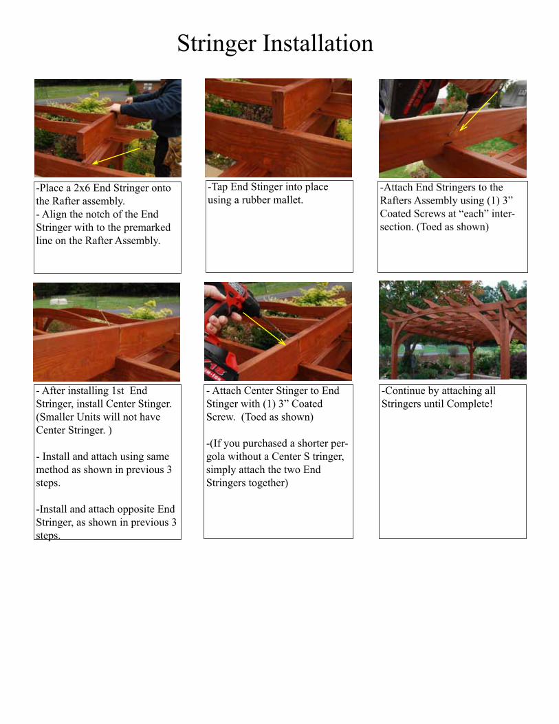
-Place a 2x6 End Stringer onto the Rafter assembly. - Align the notch of the End Stringer with to the premarked line on the Rafter Assembly.
-Attach End Stringers to the Rafters Assembly using (1) 3” Coated Screws at “each” inter-section. (Toed as shown)
-Tap End Stinger into place using a rubber mallet.
- After installing 1st End Stringer, install Center Stinger. (Smaller Units will not have Center Stringer. )
- Install and attach using same method as shown in previous 3 steps.
-Install and attach opposite End Stringer, as shown in previous 3 steps.
- Attach Center Stinger to End Stinger with (1) 3” Coated Screw. (Toed as shown)
-(If you purchased a shorter per-gola without a Center S tringer, simply attach the two End Stringers together)
-Continue by attaching all Stringers until Complete!
Stringer Installation
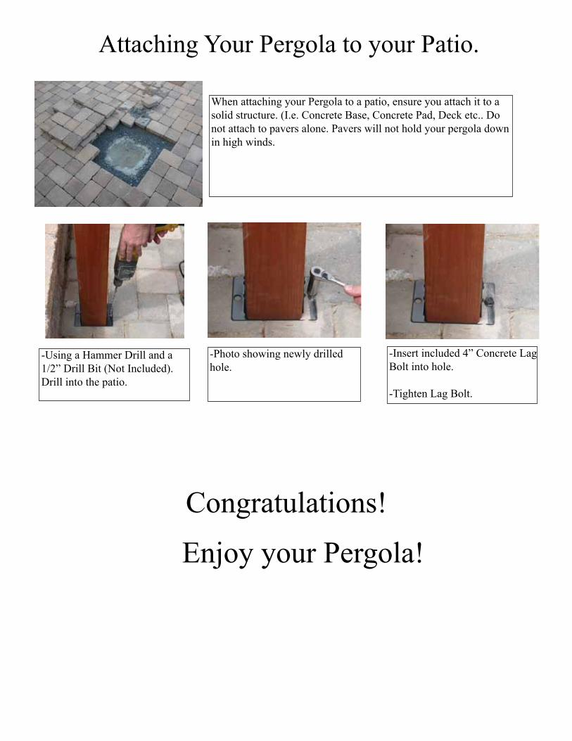
Attaching Your Pergola to your Patio.
When attaching your Pergola to a patio, ensure you attach it to a solid structure. (I.e. Concrete Base, Concrete Pad, Deck etc.. Do not attach to pavers alone. Pavers will not hold your pergola down in high winds.
-Using a Hammer Drill and a 1/2” Drill Bit (Not Included). Drill into the patio.
-Photo showing newly drilled hole.
-Insert included 4” Concrete Lag Bolt into hole.
-Tighten Lag Bolt.
Congratulations!
Enjoy your Pergola!
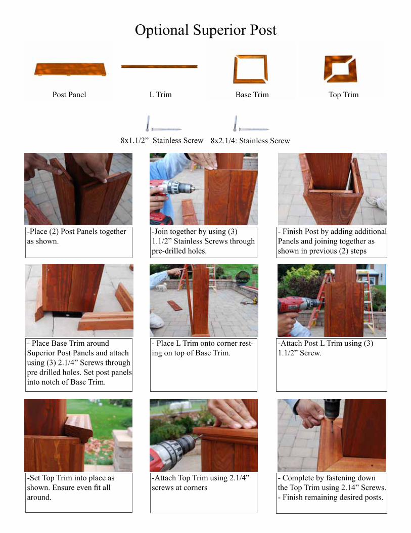
8x1.1/2” Stainless Screw
Optional Superior Post
Top TrimBase TrimPost Panel L Trim
-Place (2) Post Panels together as shown.
-Join together by using (3) 1.1/2” Stainless Screws through pre-drilled holes.
- Finish Post by adding additional Panels and joining together as shown in previous (2) steps
- Place Base Trim around Superior Post Panels and attach using (3) 2.1/4” Screws through pre drilled holes. Set post panels into notch of Base Trim.
- Place L Trim onto corner rest-ing on top of Base Trim.
-Attach Post L Trim using (3) 1.1/2” Screw.
-Set Top Trim into place as shown. Ensure even fit all around.
-Attach Top Trim using 2.1/4” screws at corners
- Complete by fastening down the Top Trim using 2.14” Screws. - Finish remaining desired posts.
8x2.1/4: Stainless Screw
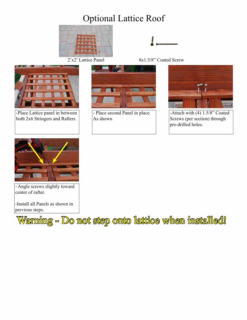
8x1.5/8” Coated Screw2’x2’ Lattice Panel
Optional Lattice Roof
-Place Lattice panel in between both 2x6 Stringers and Rafters.
- Place second Panel in place. As shown
-Attach with (4) 1.5/8” Coated Screws (per section) through pre-drilled holes.
- Angle screws slightly toward center of rafter.
-Install all Panels as shown in previous steps.
Warning - Do not step onto lattice when installed!
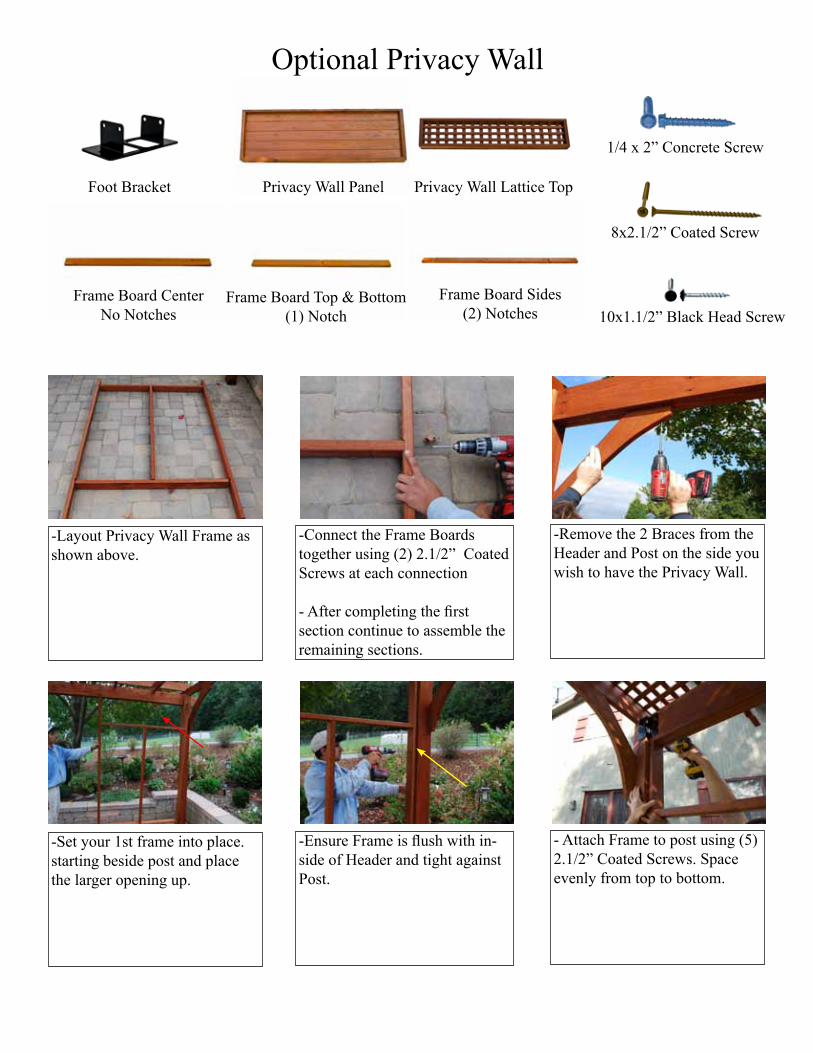
Frame Board Top & Bottom(1) Notch
Frame Board CenterNo Notches
Privacy Wall Lattice TopPrivacy Wall Panel
Optional Privacy Wall
-Layout Privacy Wall Frame as shown above.
-Connect the Frame Boards together using (2) 2.1/2” Coated Screws at each connection
- After completing the first section continue to assemble the remaining sections.
-Remove the 2 Braces from the Header and Post on the side you wish to have the Privacy Wall.
-Set your 1st frame into place. starting beside post and place the larger opening up.
-Ensure Frame is flush with in-side of Header and tight against Post.
- Attach Frame to post using (5) 2.1/2” Coated Screws. Space evenly from top to bottom.
Frame Board Sides(2) Notches
Foot Bracket
10x1.1/2” Black Head Screw
8x2.1/2” Coated Screw
1/4 x 2” Concrete Screw
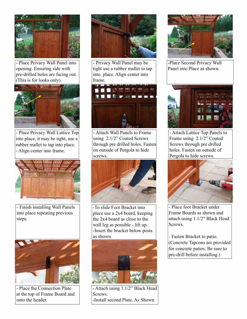
- Attach Lattice Top Panels to Frame using 2.1/2” Coated Screws through pre drilled holes. Fasten on outside of Pergola to hide screws.
-To slide Foot Bracket into place use a 2x4 board, keeping the 2x4 board as close to the wall leg as possible - lift up. -Insert the bracket below posts as shown.
- Place foot Bracket under Frame Boards as shown and attach using 1.1/2” Black Head Screws.
- Fasten Bracket to patio. (Concrete Tapcons are provided for concrete patios. Be sure to pre-drill before installing.)
- Finish installing Wall Panels into place repeating previous steps.
- Place Privacy Wall Panel into opening. Ensuring side with pre-drilled holes are facing out. (This is for looks only)
- Privacy Wall Panel may be tight use a rubber mallet to tap into place. Align center into frame.
-Place Second Privacy Wall Panel into Place as shown.
- Place Privacy Wall Lattice Top into place, it may be tight, use a rubber mallet to tap into place. - Align center into frame.
- Attach Wall Panels to Frame using 2.1/2” Coated Screws through pre drilled holes. Fasten on outside of Pergola to hide screws.
- Place the Connection Plate at the top of Frame Board and onto the header.
- Attach using 1.1/2” Black Head Screws. -Install second Plate. As Shown.
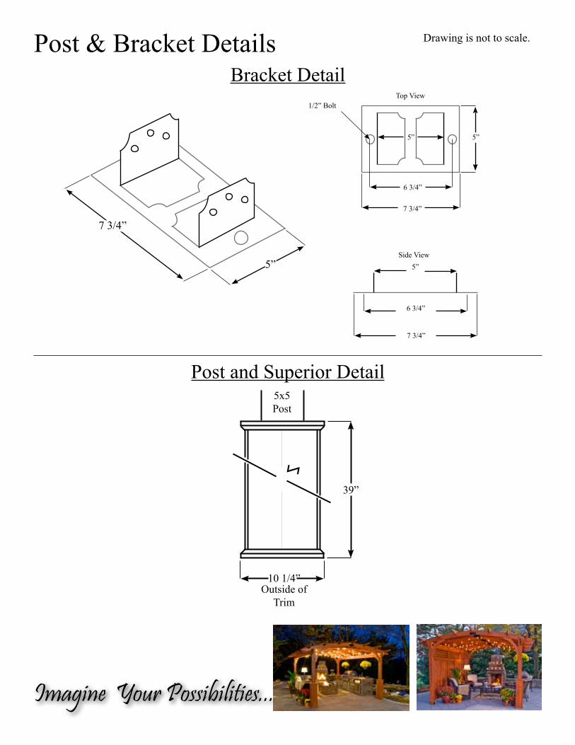
Post & Bracket Details Drawing is not to scale.
5”
7 3/4”
6 3/4”
Side View
Z
10 1/4”
39”
Outside of Trim
5x5Post
5”
7 3/4”
6 3/4”
Top View1/2” Bolt
7 3/4”
5”
5”
Bracket Detail
Post and Superior Detail
Imagine Your Possibilities...