heat engines vol 1 1... · prime-movers, particularly in the textile industry. ... slide valve,...
TRANSCRIPT

\
STEAM ENGINES9.1 Heat Engines
Heat engines may be divided into two main classes, according to where the combustion of fuel takes place. In one class, the combustion of fuel takes place outside the cylinder, and such an engine is called external combustion engine. The most common examples of this class are steam engines and steam turbines, where the working medium is steam. In an external combustion engine the power is produced in two stages. The energy released from the fuel in the furnace of the boiler is first utilized to evaporate water in a boiler and then the steam so produced is made to act on the piston of the steam engine or on the blades of the steam turbine producing power. When the combustion of fuel takes place inside the engine cylinder so that the products of combustion directly act on the piston, the engine is known as internal combustion engine. Diesel engine, gas engine and petrol engine are the common examples of this class where the working medium is the products of combustion.
Steam engines were manufactured upto the year 1930 for use as stationary prime-movers, particularly in the textile industry. They are still used for locomotives for railways and now slowly they are being replaced by Qiesel locomotives. In addition, they are used on ships where they are slowly being replaced by steam turbines and Diesel engines.9.2 Steam Engine Plant
As steam engine plant consists essentially of three main units : Boiler, Engine and Condenser. In many cases, particularly in locomotive steam engines, a separate condenser is not provided and the engine exhausts into the atmosphere.
The steam from the boiler is admitted into a steam chest from where it enters the engine cylinder through a valve driven by an eccentric on the engine crankshaft.
k i g . 9 1 . S i d e v i e w o f a h o n z o n t a l s i m p l e s t e a m e n g i n e .
- ' — "^ 3'Frome
After expansion in the engine cylinder and doing work on the piston, the steam is exhausted into a con-denser where it is condensed and re-turned as feed water to the boiler, thus, completing the cycle. Nearly all reciprocat-ing steam engines are
H E I - 16

242 EL EMENTS OF HEAT ENGINES Vol.l
double-acting, i.e. steam is admitted in turn to each side of the piston and two working strokes are produced during each revolution of the crankshaft.
Figure 9-1 illustrates a simple form of a single-cylinder, horizontal, reciprocating steam engine. The figure shows major principal parts of the engine.9.3 Classification (Types)
Steam engines may be classified in the following ways :.. Position of the axis of the cylinder: Vertical, Inclined or Horizontal engine... According to the action of steam upon the piston : Single-acting or Double-acting engine... Number of cylinders used in which steam expands : Single-expansion or Simple engine
(total expansion of steam in one cylinder), and Multiple-expansion or compound engine (total expansion of steam in more than one cylinder).
.. Method of removal of exhaust steam : Condensing or Non-condensing engine.*
.. Magnitude of rotative speed : Low, Medium or High speed engine.
.. Type of valve used : Slide valve, Corliss valve or Drop valve engine.
.. Use or field of application : Stationary, Portable (movable), Locomotive, Marine engine.9.4 Parts of Steam Engine
The parts of steam engine may be broadly divided into two groups, namely, stationary parts and moving parts.
- Stationary parts : Engine frame, Cylinder, Steam chest, Stuffing box, Crosshead guides and Main bearings.
- Moving parts : Piston and piston rod. Crosshead, Connecting rod, Crankshaft, Flywheel, Slide valve and valve rod, Eccentric and eccentric rod and Governor.
The function of the steam engine parts are as follows :The engine frame is a heavy casting which supports all the stationary as well as
moving parts of the engine and holds in proper alignment. It may rest directly on the engine foundation or upon the engine bed plate fixed on the engine foundation.
The cylinder shown in fig. 9-2 is a cast iron cylindrical hollow vessel in which
Slide valvethe piston moves to and fro under the pressure of the steam. Both the ends of the cylinder are closed by covers and made steam- right.
The steam chest is a closed chamber integral with the cylinder. It supplies steam to the cylinder with the movement of the slide valve.
f ig 9 Li -c tto n a l v i e w o f g t i M m e n g i n e c y liin l*» r . p i s t o n , s lu t t in g b o x , s t e a i n
c h e s t a n d s li d e v a l v e .
The stuffing box and gland are fitted on the crank end cover of the cylinder as shown in fig. 9-2 and
STEAM ENGINES 243
their function is to prevent the leakage of steam past the piston rod which moves to arid fro.
The piston is a cast iron cylindrical disc moving to and fro in the cylinder under the action of the steam pressure. Its function is to convert the heat energy of the steam into mechanical work. Cast iron piston rings make the piston steam tight in the cylinder and thereby prevent the leakage of steam past the piston.
The CTosshead is a link between piston rod and the connecting rod.' It guides the motion of the piston rod and prevents it from bending.
The connecting rod helps in converting the reciprocating motion of the piston into rotary motion of the crank. Its one end is connected to the crosshead by means of gudgeon pin or crosshead pin and other end is connected to the crank.
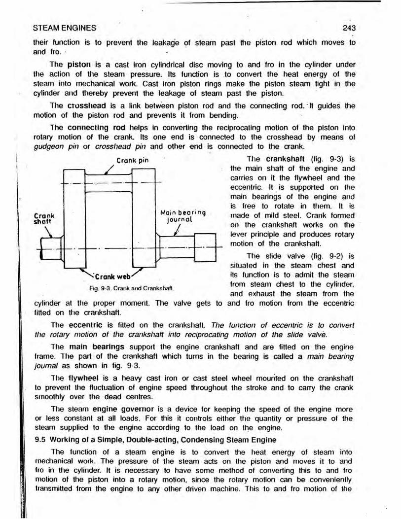
Crank pin The crankshaft (fig. 9-3) isy -------- the main shaft of the engine and
carries on it the flywheel and the eccentric. It is supported on the main bearings of the engine and is free to rotate in ttiem. It is made of mild steel. Crank formed on the crankshaft works on the lever principle and produces rotary motion of the crankshaft.
The slide valve (fig. 9-2) is situated in the steam chest and its function is to admit the steam from steam chest to the cylinder, and exhaust the steam from the
Crankshaft
Main bearing journal
Crank web4 Fig. 9-3. Crank and Crankshaft.
cylinder at the proper moment. The valve gets to and fro motion from the eccentric fitted on the crankshaft.
The eccentric is fitted on the crankshaft. The function of eccentric is to convert the rotary motion of the crankshaft into reciprocating motion of the slide valve.
The main bearings suppoit the engine crankshaft and are fitted on the engine frame. The part of the crankshaft which turns in the bearing is called a main bearing journal as shown in fig. 9-3.
The flywheel is a heavy cast iron or cast steel wheel mounted on the crankshaft to prevent the fluctuation of engine speed throughout the stroke and to carry the crank smoothly over the dead centres.
The steam engine governor is a device for keeping the speed of the engine more or less constant at all loads. For this it controls either the quantity or pressure of the steam supplied to the engine according to the load on the engine.9.5 Working of a Simple, Double-acting, Condensing Steam Engine
The function of a steam engine is to convert the heat energy of steam into mechanical work. The pressure of the steam acts on the piston and moves it to and fro in the cylinder. It is necessary to have some method of converting this to and fro motion of the piston into a rotary motion, since the rotary motion can be conveniently transmitted from the engine to any other driven machine. This to and fro motion of the

244 • ELEMENTS OF HEAT ENGINES Vol.l
piston is converted into rotary motion with the help of connecting rod and crank of the steam engine.
Gland
Piston red
yUnder
ValveSteam chest
Steamport
Cylinderoover PistonFig 0 4. Sectional pictorial view of horizontal steam engine cylinder, piston,
stuffing box and gland, steam chest and D-slide valve.
figure) through the steam port and the exhaust port as shown in fig. 9-4. This steam admitted to the cover end exerts pressure on surface of the piston and pushes it to crank end (right hand side) of the cylinder.
At the end of this stroke, fresh steam from the steam chest is again admitted by the D-slide valve to the crank end of the cylinder (when admission steam port is opened), while the exhaust steam on the cover end of the cylinder passes at the same time into the condenser through steam port and exhaust port. Thus, the steam at the cover end exhausts while that at the crank end pushes the piston back to its original position.
The D-slide valve gets to and fro motion from the eccentric fitted on the c r a n k s h a f t .
Thus, two working strokes are completed and the crankshaft turns by one revolution, i.e., the engine is double-acting. These operations are repeated.
When the exhaust steam is exhausted to atmosphere, the engine is known as non-condensing engine.
The motion of the piston and piston rod moves the crosshead, connecting rod, crank and crankshaft. The motion of the piston, piston rod and crosshead is to and fro. This to and fro motion is coverted into rotary motion with the help of the connecting rod, crank and the crank pin as shown in fig. 9-1. The end of the connecting rodwhich is attached to the crosshead can only move in a straight line, while the otherend attached to the crank pin can move only in a circle, since, the crank carrying the crank pin is free to turn the crankshaft. The motion of the connecting rod is, thus, oscillating. Since, the crank is fixed on the crankshaft, the crankshaft will rotate in its bearing. The flywheel is mounted on the crankshaft.
The following terms are useful in understanding the working of the steam engine :The cylinder bore is the inside diameter of (he cylinder or the liner.The piston stroke is the distance travelled (or moved) through by the piston from
one end of the cylinder to the other end, while the crank is making half a revolution.
The steam (fig. 9-4) is first admitted to the cover end (left hand side) of the cylinder from the steam chest when steam admission port is un-covered (opened) by the D-slide valve, while the exhaust steam (which has done work on the piston) on the crank end (right hand side) of the cylinder passes at the same time into a vessel, called con-denser (not shown in the

STEAM ENGINES 245
Two strokes of the piston are performed per revolution of the crankshaft.The forward stroke is made by the piston while it moves from the head end to
the crank end.
The return stroke is made while the piston travels from the crank end to the head end.
The crank throw or crank radius is the distance between the centre of the crankshaft and the centre of the crank pin. This distance is equal to half the travel of the piston, i.e., piston stroke.
The piston displacement or swept volume is the volume swept by the piston while moving from one end of the cylinder to the other end, while the crank is making half a revolution.
The average linear piston speed is the rate of motion of the piston expressed in metres/minute. It is equivalent to twice the product of the piston stroke (I) in metres and the number of revolutions of the engine per minute (N),. i.e., piston speed = 2IN metres/minute.
The dead centres are the positions of the piston at the end of the stroke when the centre lines of the piston rod, the connecting rod and the crank are in the same straight line. There are two such dead centres, one for each end of the piston stroke. For hoiizontal engines, the two dead centres are known as inner dead centre and outer dead centre. For vertical engines, the two dead centres are known as top dead centre and bottom dead centre.
Clearance volume is the volume of the space between the piston and the cylinder cover, when the piston is at the end of the stroke, plus the volume of the steam port leading to this space.9.6 Hypothetical Indicator Diagram
An indicator diagram is a plot of steam pressure in the cylinder on the bdsis ot steam volume during the cycle of operations. The theoretical indicator diagram can ue constructed geometrically or by calculating pressure of steam at different points of the stroke by applying the law, pv = constant, for the expansive working of steam and then raising the ordinates to get the points of the curve. Such a diagram (fig. 9-5) is known as theoretical or hypothetical indicator diagram because it is constructed after making certain assumptions as follows :
- The opening and closing of the ports is sudden.- There is no pressure drop due to condensation.- There is no pressure drop due to wire-drawing which is due to restricted port or valve
opening.- There is no compression to create the cushioning effect on the piston at the end of the
stroke.- The steam is admitted at boiler pressure and exhausted at atmospheric or condenser
pressure.- The expansion of steam is hyperbolic, following the law pv = constant.- The clearance volume is neglected.
Referring to fig. 9-5, steam is admitted at point a. It is termed as the point of

p admission. Steam is supplied to the cylinder at constant pressure, pi up to point of cut-off, b. Steam then expands in the cylinder as the piston moves further. This is accompanied by fall in pressure. The law of expansion be is assumed as pv = constant. Expansion is carried to the end of the stroke. At point c, release of steam takes place. The pressure falls instantaneously to exhaust pressure or back pressure, pb represented by line cd. Exhaust takes place at constant pressure pb and conditions throughout the whole exhaust stroke are represented by line de.
From a thermodynamic stand point, it should be assumed that the expansion of an ideal diagram
(■ icj. 9 5 t h o o i >>ticai o r h y p o t h e t i c a l i n d i c a t o r is adiabatic. However, such a condition never occurs diagram without clearance and compression, in practice because some of the steam condenses
before cut-off takes place and the steam is always more or less wet at the beginning of expansion, unless the steam is highly superheated at admission. Condensation also proceeds during part of the expansion and then a certain amount of re-evaporation occurs towards the end of expansion. All these factors take the expansion curve away from an adiabatic curve and very close to pv m constant curve or hyperbolic curve.
9.6.1 Hypothetical Mean Effective Pressure : As shown earlier, if the pressure and volume are plotted in kPa and in3 respectively, the area of p - v diagram represents the work done in kJ.
(i) Hypothetical indicator diagram without considering clearance and compression :
2.4fi ELEMENTS OF HEAT ENGINES Vol.l
Volume
Referring to fig. 9-6.Pt * admission pressure kPa (or kN/m2),Pb = back pressure in kPa ( oi kN/M2),V/ = volume of steam in the cylinder
at cut-off in m3, andv2 = swept volume in m .Work done per cycle in kJ = area of hypothetical indicator diagram= area a-b-c-d-em area a-b-g-o plus area b-c-f-g minus
area d-e-o-f( Vz'
= pivi 1 + log«
Vi
~PbVZ
- PbVZ
I iy 9 6 Hypothetical indicator diagram without clearance and compression.
Area of hypothetical indicator diagram_____Hypothetical m.e.p. = Length of the base 0j hypothetical indicator diagram
STEAM ENGINES
= Work_done per cycle in kJ kpa (<jr kN/m2}Swept volume In m
= Pv
V2
1 + loge
1 + log*
„ \ V2le
V\v - M
^2
VZh
V P
- PbvZ
Pb
But, ^ = r (expansion ratio)
Hypothetical m.e.p. ** P1 11 + loge (0 ] - Pb kPa (or kN/m?)2
where pi and Pt, are pressures of steam In kPa (kN/m )
It may be noted thatvyvz
~ cut-off ratio.
247
(9.2)
Problem-1 : Steam is admitted to the cylinder of a steam engine at a gauge pressure of 1,050 kPa (1 05 MPa) and is cut-off at VS stroke. The back pressure is 15 kPa. Calculate the hypothetical mean effective pressure in kPa and kN/m2 on the piston during the stroke. The barometer reads 96 kPa. Neglect clearance.
Using eqn. (9-2), Hypothetical m.e.p. = -- [1 + log© (r)] - pb kPa
Here absolute pressure, p i = gauge pressure + atmospheric pressure= 1,050 + 96 = 1,146 kPa
Expansion ratio, r = - - ]. - = H ry cut off ratioSubstituting the values in eqn. (9.2), we have
1,146
= 3, and Back pressure, pb = 15 kPa.
Hypothetical m.e.p. = f f + loge (3)J - 15
1,146 [1 + 1 0986] - 15
* 786 66 kPa = 786 66 kN/nrNote : 1 kPa = 1 kN/m2 and 1 MPa = 10 bar = 1 MN/m2.Hypothetical indicator diagram considering clearance and compression :Refer to fig. 9-7. The compression starts at e and finishes at f which is also the
point of admission. The admission is continued up to b. The expansion curve is represented by be. c is the point of release and de is exhaust line. The compression curve is represented by ef. The expansion and compression curves are assumed to be hyperbolic.
Let v = volume swept by the piston in one stroke in m ,c - fractional ratio of clearance volume to swept volume v,

18 ELEMENTS OF HEAT ENGINES Vol.
x = fractional ratio of the volume between points of compression and admission to the swept volume v,k = 1/r = fractional ratio of the volume between the points of ad-mission and cut-off to the swept volume v,
Pi = initial pressure of steam or boiler pressure in kPa, andft, = back pressure of steam or condenser pressure in kPa.Net work done per cycle = area a -b -c -d -e -f
= area a -b s -r plus area b-c-w -s minus area e-d—w -t minus area f-e -t-r
h y \) 7 I l y p o t h e t i c a l in d i c a t o r d i a g r a m w i t h c l e a r a n c e a n d
c o m p r e s s i o n .
P! x kv + pi (kv + cv) + log<v+ cv
kv+ cv
= v Pi I k + (k + c) log* (1 + c) k+ c
- Pb ( V - XV)
- Pb (xv + cv) loge
Pb\0 - x) + (x+c) loge
XV + cv cv
x+ c c
.. . • , r, Work done per cycle in kJThus, hypothetical m.e.p. in kPa m - - . r _ _ —
(9.3)
Swept volume in mwr [, , f 1 + rM f . ' X + c' vPt l k + (k+c) log* k+ c
\ .... - iJ- - Pb j ( i - x)(x+ c) log0 c II,
Since k = , Hypothetical m.e.p.
1 f l 1•oge'1 + r '
Pi +r -I cr 1 + c- Pb
rk t
(1 - x) + (x + c) loge ' x + c '
/J
..(9.4)
If the compression effect is neglected, i.e. x = 0, the eqn. (9.4) becomes,
Hypothetical m.e.p. * pi + c loge f1 + c N 1- + c
- pb 1 + C loge c \ p
= pi ‘ c log* ( \ fC ) 1 + c
- Pb ..(9.5)
II the effect of clearance volume is neglected, i.e., c = o, the eqn. (9.5) becomes,

STEAM ENGINES 249
Hypothetical m.e.p. = Py [1 + loge (a)] - pb ..(9.6)
This is same as expression (9.2) directly derived earlier.Point of cut-off is the point at which the supply of steam to the cylinder is closed.
Cut-off ratio is expressed as the ratio of the volume of steam in the cylinder when the piston is at the point of cut-off, and the volume of steam in the cylinder when the piston is at the end of the stroke. If the clearance is not considered while taking the volume of steam at the point of cut-off and at the end of the stroke, the cut-off is known as apparent cut-off. If the clearance is taken into account, this ratio is known as real cut-off. Thus, referring to fig. 9-7,
..(9.7)Apparent cut-off ratio m - - = k -v r
Real cut-off ratio = kv+ cv v+ cv
/c+ c 1 + c
..(9.8)
Ratio of expansion is the ratio of the volume of steam at the end of the stroke, and the volume of steam at the point of cut-off. It is the reciprocal of the cut-off ratio. If no account is taken of the clearance volume while considering this ratio, the ratio is called apparent or normal ratio of expansion. If the clearance volume is considered, the ratio is known as real or actual ratio of expansion.
1 .. (9.9)Apparent expansion ratio = kv = r
and real expansion ratio = (9.10)v+ cv _ 1 + c kv+ cv ~ k + c
Problem-2 : Steam is admitted to the cylinder of a single cylinder engine at a pressure of 1,400 kPa and it cut-off at 025 of the stroke. The back pressure is 120 kPa and the clearance volume is 10% of the swept volume. Calculate the hypothetical (theoretical) mean effective pressure on the piston during the stroke.
Using eqn. (9.5),
Hypothetical m.e.p., = pi
1
1 1 + c log£M ± c \ 1 + c
Pb
Here, = 0 25, c = 0 1, p i = 1,400 kPa, and pb = 120 kPa.
Hypothetical m.e.p. = 1,400 0 25 + (0 25 + 0-1) loge( 1 4 0 1
- 120025 + 0 1k
= 1,400 [0 25 + 0 35 x 1 1442] - 120 = 790 66 kPaProblem-3 : The cylinder of a non-condensing steam engine is supplied with steam at 1,220 kPa. The clearance volume is 1/10th of the stroke volume and the cut-off takes place at 1/4th of the stroke. If the pressure at the end of compression is 550 kPa, calculate the value of mean effective pressure of the steam on the piston. Assume that expansion and compression are hyperbolic. Take back pressure as 110 kPa.
Let v = stroke volume, and cv = clearance volume,then the volume of steam at the beginning of the compression stroke = v (x + c)
where, x = compression ratio without considering clearance volume, and the volumeof steam at the end of compression = cv.Applying hyperbolic law between the points of beginning and end of compression,
110 (c + x) v = 550 x cv i.e. 110 (0 1 + x) v= 550 xO I v i.e., 0 1 + x = 05 x = 0 4
Here, - = c= 0 1, p i = 1,220 kPa, pb = 110 kPa, and x= 0 4.r 4
250 ELEMENTS OF HEAT ENGINES Vol.!
Now, using eqn. (9.4), Hypothetical m.e.p.
= P11 (1 + c log« f 1 -+ c)
1 + c- P b (1 - X) + (x + c) loge x + c
c / J
= 1,220 + 0 1 log* (1 + 0-1 1
! + o i110 (1 -0-4) +(0-4 + 01) loge 0 4 -» 0-1 ^
0-1
= 1,220 (0 25 + 0 35 loge 3 14) - 110 [0 6 + 0-5 x log© 5]= 1,220 [0-25 + 0 35 x 1 1442] - 110 [0 6 + 0 5 x 1-6094] = 6391 kPa
Problem-4 : In a steam engine. steam is admitted for 40% of the working stroke.Clearance volume is 10% of the swept volume. Calculate the apparent and real valuesof cut-off and expansion ratios.
Assuming the swept volume = 100 units,Apparent ratio of cut-off = 40/100 = 0 4 andApparent ratio of expansion = 100/40 = 2-5
total volume of steam at cut-off total cylinder volume
total volume of steam at cut-off _ 40+10 swept volume + clearance volume ~ 100 + 10
total cylinder volume _ 100 + 10
Real ratio of cut-off =
= 0454
Real ratio of expansion = total volume of steam at cut-off 40 + 10= 22
9.7 Cylinder CondensationIf saturated steam is brought in contact with a surface colder than temperature of
the steam, condensation of steam begins immediately. During condensation the steam gives up part of its latent heat and becomes wetter.
During the period of exhaust, the cylinder walls are cooled by contact with the relatively cool low pressure exhaust steam. When the hot steam from boiler is admitted to the cylinder, a part of it condenses as it comes in contact with previously cooled cylinder walls during the exhaust slroke. The water thus formed by the process of condensation is deposited in the foim of a thin film on the walls of the cylinder. The heat received by the cylinder walls from the fresh hot steam will be given back to the deposited film of water during the time the steam expands and consequently falls in temperature after the cut-off takes place. This transferred heat from the cylinder walls

STEAM ENGINES 251
to the water film will re-evaporate some of the water into steam at the end of expansion stroke.
The condensation, thus, takes place during the early part of the admission stroke, re-evaporation occurs partly towards the end of the expansion stroke, and partly during exhaust stroke. The re-evaporation during expansion period behind the piston increases the total work done. But, the re-evaporated steam during the exhaust period in a single cylinder engine passes away to waste, without doing any useful work. However, in a compound steam engine this re-evaporated steam will be utilized in the next cylinder to which the steam is led from the first cylinder. Any degree of condensation results in loss of energy available for doing useful work, and this loss may vary from 10% to 40% of the available energy of the steam.
The methods adopted to reduce the amount of condensation of steam in the cylinder are :
- Obtaining the steam from the boiler in superheated state and lagging the steam pipe from boiler to engine by non-conducting material such as asbestos.
- Jacketing the cylinder with hot steam from the boiler.- Compounding the cylinders, and thereby reducing the range of variation of temperature
In each cylinder.9.8 Actual Indicator Diagram
An actual indicator diagram obtained on a steam engine is more likely to be of the form shown dotted in fig. 9-8. The hypothetical indicator diagram of this engine is shown in full lines.
The difference between two diagrams is on account of certain practical factors given below, which were not considered in arriving at the hypothetical indicator diagram :- The big drop in the steam
pressure between boiler and the engine cylinder is due to con-densation caused by loss of heat in steam pipes, friction losses in the steam supply pipe and
admission valve and to wire-drawing in the valves. This pressure difference will tend to increase toward the point of cut-off due to increasing velocity of the piston and consequent increased demand for steam and due to condensation of steam in the cylinder.
..The opening and closing of the ports is a gradual process as the valve moves over it. The pressure changes at the opening and closing of ports are not as sudden as shown on the hypothetical diagram, and there is rounding-off of the actual diagram at the beginning of admission, cut-off and release.
.. The actual expansion curve is not a true hyperbola owing to the varying intercharge of heat through the cylinder walls. At the commencement of the expansion, the steam in
.3
o»
Volume ■
Fig. 9 8. Superimposed actual aiid hypothetical indicator diagrams.

252 ELEMENTS OF HEAT ENGINES Vol.l
Diagram factor, f =
the cylinder is hotter than the cylinder wall; this causes condensation of steam and the volume of steam consequently decreases. Near the end of the expansion stroke, owing to the low pressure of steam, the steam is colder than the cylinder walls; this causes heat to flow from the cylinder walls to the steam which tends to re-dry the steam.
.. The release (opening of exhaust port) occurs before the end of the expansion stroke, and the time factor in the opening of the exhaust port will cause the rounding-off of the toe of the actual diagram.
.. Exhaust pressure in the cylinder will not be quite so low as the condenser pressure because the size of the exhaust port is limited and therefore, the exhaust from the port is not quick.
.. There is rounding-off of the heel of the actual diagram due to closing of the exhaust port before the end of the stroke. This results in compression of the steam in the cylinder, which serves as a soft cushion for bringing the piston to rest at the end of the stroke. Admission occurs just before the end of the compression stroke.
It will be seen from fig. 9-8 that the area of the actual indicator diagram is less than the area of the hypothetical indicator diagram. The ratio between the areas of these two diagrams is known as the diagram factor. Or
Area of actual indicator diagram Area of hypothetical indicator diagram
mean height of actual indicator diagram mean height of hypothetical indicator diagram
m.e.p. from actual indicator diagram ..(9.11)m.e.p. from hypothetical indicator diagram
The diagram factor varies slightly with different types of engines, and its average value is about 0-75.
9.8.1 Indicator : Instrument used for drawing diagrams showing actual pressure - volume relations within the engine cylinder during one revolution of the engine crank is called indicator. The diagram is drawn on a piece of paper usually called an indicator card. The diagram showing actual pressure-volume relations within the engine cylinder
is called an indicator diagram (fig. 9-8). The length of the indicator diagram repre-sents the length of the stroke to a reduced scale and its height at any point represents the pressure on the piston at the cor-responding point in the stroke. For double- acting steam engines a separate diagram is taken for each end of. the cylinder.
A common form of steam engine indicator, shown in. fig. 9-9, consists of two main parts :- a small cylinder, communicating at one
end with the engine cylinder, and- a drum for holding the indicator card.
The small cylinder contains a dose- fitted piston to which is attached a strong
F ... 9-9. Sectional view ol inside spring indicator.
Pencil lever
Link
— Drum
Spring
Bgdy or cylinder
Coil spring
Guide pulley for cord

STEAM ENGINES 253
helical spring. The piston is forced upward against the resistance of this spring by the steam pressure in the engine cylinder and forced downward by the spring when the steam pressure drops. The end of the piston rod of the indicator piston is attached through a series of links to a pencil lever that has a pencil point on its free end. The links are so designed that they magnify the motion of the indicator piston at the pencil point and yet cause it to move in a truly vertical line.
A coiled spring attached to the inside of the drum resists the pull of the cord onthe outward stroke and keeps the cord tight on the return stroke.
In operation, the indicator card is wrapped around the indicator drum and held against it by spring clamps. One end of a fine cord is attached to and wrapped several times arround the groove at the base of the drum, and the other end is attached tosome form of reducing motion, which in turn is connected to a reciprocating part ofthe engine, preferably to the engine crosshead pin. When indicator cylinder is put in communication with the engine cylinder, the lever carrying the pencil point will rise and fall according to the rise and fall of steam pressure. At the same time the drum will be rotated back and forth in some proportion to the engine stroke. Now, if the pencil point is pressed against the indicator card, it will trace an indicator diagram on the indicator card.9.9. Power and Efficiencies
9.9.1 Indicated Power : The power developed in the cylinder of any engine is commonly known as indicated power. Thus, indicated power is the rate of doing work on the moving piston in the cylinder. It is called indicated power because an instrument known as the indicator, is used to measure it. The power developed in the cylinder of any engine can be determined, if the engine cylinder diameter, piston stroke and speed are known, and if an indicator diagram with its spring scale or number is available.The first step is to find the mean effective pressure. The mean effective pressure isthe average effective pressure on the piston.
.. . . . . , . .. , .. . area of indicator diagram in mmMean height of indicator diagram in mm, h = j ■■ .. - : * -------s—a 3 length of indicator diagram in mmIndicated mean effective pressure in kPa or kN/m = mean height, h in mm x springscale or spring number, kPa or kN/m per 1 mm elongation.The mean effective pressure is a constant pressure which will do the same work
as the actual varying pressure. Hence, the actual varying pressure in the engine cylinder can be replaced by the mean effective pressure. To find the power, we must know the woik done per second. This wjll be equal to the amount of work done per strokemultiplied by number of working strokes per second.
If pm = actual mean effective pressure of steam in N/m2 or Pa,a = area of the piston in m2,I = length of piston stroke in metre, and
N = number of revolutions made by the engine per second (r.p.s),Then, driving force on the piston during a stroke = pm x a newtonsand Work done per stroke ** pm x a x I N-m (newton-metre) or J (joules)Since two working strokes are obtained in one revolution in a double-acting steam
engine,

254 ELEMENTS OF HEAT ENGINES Vol.l
Work done per second = pm x a x I x 2N J/s or W (watts)/. Indicated power = 2 x p m x a x / x / V W
or _ 2 X_jBm[ X A I L l x J ! . kw -(9-12)or “ 1,000 kW U
A portion of the power developed in the engine cylinder is absorbed in overcoming the friction of the moving parts of the engine itself. The remainder is available for doing the required work. The power absorbed in overcoming the frictional resistance of the moving parts of the engine is termed frictional power.
9.9.2. Brake Power : The actual power available from the engine for doing useful woik is termed the brake power or shaft power. The brake power of an engine can be determined by a brake of some kind applied to the brake pulley of the engine. The arrangement for the determination of brake power of the engine is known as dynamometer.
Dynamometers are broadly divided into two classes :— Absorption dynamometres, and— Transmission dynamometers.
In absorption dynamometer, the power available from the engine is absorbed in the form of friction at the brake. In transmission dynamometer, the power available from the engine is not wasted in friction. Transmission dynamometer transmits the power and measures it at the same time.
Absorption brake dynamometers are those that absorb the power to be measured by friction. This power absorbed in friction is finally dissipated in the form of heat energy. Common forms of absorption dynamometers are : the rope brake, the prony brake, the fan brake, the hydraulic brake and the electrical brake.
Rope brake dynamometer is a convenient type of brake and can be applied tothe flywheel of a moderate size engine. The rope brake consists of a double rope passed round the brake wheel as shown in fig. 9-10, the upper end is connected to a spring balance suspended from overhead and the lower end carries the load W in newtons. The load W is usually called dead load. The ropes are generally held apart by the wooden blocks.
Tw
Fig 9-10. Rope brake dynamometer.
The pull S in newtons indicated by the spring balance, is helping to turn the wheel while the load IN is opposing its rotation. The direction of the rotation of the wheel is shown by the arrow. At the given load the whole power developed by the engine is absorbed by the friction produced at the rim of the wheel. Since, the whole power is converted into heat, the rim of the wheel must be water cooled.

STEAM ENGINES 255
The net resistance against the wheel or the frictional force or the net load «* (W - S) newtons. If R is the effective radius of the wheel in metres which works as
D -f- (jthe torque arm for frictional resistance, i.e. R = —=■ (wheel D = diameter of the brake
wheel and d = diameter of the brake rope) then, the frictional torque = the resisting force x arm = (W - S) x R N-m.
If N = number of revolutions made by the engine per second (r.p.s), then the number of radians per second = 2nN.
The work absorbed = (W - S) R x 2itN N.m/s or J/s or W (watts)n l. ( W - S ) R x 2 n N ....Brake power = v j -------- kW
_ Torgue x 2 n N . „ .1,000
..(9.13)
Power lost in overcoming the friction of rotating and sliding parts of the engine is the difference between the indicated power and brake power.
i.e. Friction power = Indicated power - Brake power .. (9.14)9.9.3 Mechanical, Thermal and Overall Efficiencies : The performance of steam
engines is usually stated in terms of the followings :— Mechanical efficiency,— Thermal efficiency, and— Overall efficiency.The mechanical efficiency of engine takes into account the energy loss due to the
friction of the moving parts of the engine, and is calculated from the relation between the brake power and the indicated power. The power lost in friction is the difference between the indicated power and the brake power.
It is generally assumed that friction power is the same at all loads at constant speed. However, various tests indicate that the friction power generally increase with the load but not to any considerable extent.
The mechanical efficiency is defined as the ratio of the power output of the engine, as measured by the brake, to the power developed by the steam in the engine cylinder, as obtained from the indicator diagram,
.. t . . „. . Brake power .. (9.15)i.e. Mechanical efficiency, r\m = . .. .-,rIndicated powerThe mechanical efficiency of high speed steam engines at full load is generally
between 80 to 90 per cent. With forced lubrication, its value at full load is still higher.The thermal efficiency is defined as the ratio of the heat converted into useful
work, to the heat supplied. The heat supplied per kg of steam to the engine may be worked out as the difference between the enthalpy, Hi of steam at conditions existing at engine stop valve and the enthalpy h2 of water at the temperature of engine exhaust (heat of water or condensate returned to hot-well). So, heat (net) supplied in kJ per kg of steam = Hi - h2.
The useful work obtained may be worked out either from indicated power or brake power. If the heat equivalent of indicated power developed by the engine is considered

as the output, the efficiency is termed indicated thermal efficiency,■ ,. . . .. _ . . Heat equivalent of indicated power in k j/seci.e. Indicated thermal efficiency, 11/ = ------- . / - - \ ------ - ------Heat supplied in steam in kJ/sec.
Indicated power in kW ..(9.16)ms (Hi - hz)
where, ms - steam consumption in kg/sec,Hi = enthalpy of 1 kg of steam supplied in kJ, andh2 = enthalpy of 1 kg of water of exhaust steam in kJ.
„ . . «. • Heat equivalent of brake power in kJ/sec.Brake thermal efficiency, = -------------------.. .. 4 r . . ----------1 ' Heat supplied in steam in kJ/sec.Brake power in kW ..(9.17)
ms { Hi - hz)
where, ms = steam consumption in kg/sec.Hi = enthalpy of 1 kg of steam supplied in kJ, andh2 = enthalpy of 1 kg of water of exhaust steam in kJ.
Comparing eqns. (9.15), (9.16) and (9.17),................. ...... . Brake thermal efficiency ..(9.18)Mechanical efficiency, r\m = . .. . . ». .’ 1 Indicated thermal efficiencyThe overall efficiency of steam engine plant is defined as the ratio of the power
output of the engine as measured by the brake to the heat energy supplied by the fuel,
i.e. Overall efficiency of steam engine plantHeat equivalent of brake power in kJ/sec.
Heat supplied by fuel in kJ/sec.brake power in kW ..(9.19)
nif x C.V.
where, nv = fuel supplied to the boiler in kg/sec, andC.V. = calorific value of fuel used in the boiler in kJ/kg.
Problem-5 : A single-cylinder, double-acting steam engine of 20 cm diameter and 40 cm stroke is supplied with steam at 834 kPa and exhausts at 147 kPa. Cut-off takes place at ^ rd stioke and the engine runs at 2 r.p.s. Using a diagram factor of 07, estimate the actual mean effective pressure and the indicated power of the engine.
Here, p i = 834 kPa, Expansion ratio, r = q 0fl = 1a = an<* Pb - 147 kPa.
Using eqn. (9.2), hypothetical m.e.p.
= Pr1 [1 + loge ( i - Pb = [1 + l°9e (3)] - 14 7 = 5686 kPa
. . Actual m.e.p., pm = diagram factor, f x theoretical m.e.p.= 0 7 x 568 6 = 398 02 kPa.
256 ELEMENTS OF HEAT ENGINES Vol.l
Using eqn. (9.12), Indicated power = 2 x p m x a x / x A / watts

STEAM ENGINES 257
where, pm = actual m.e.p. = 39802 x 10 Pa
a = area of the piston = f 20 n2 100
40
m
/ = length of piston stroke = m, and
N = number of revolutions made by the engine ■ 2 r.p.s. Substituting the above values, .
Indicated power = 2 x 398-92 x 103 x ~ ( 20 100
\2 40 0x x 2 100= 20,000 W or 20 kW.
Problem-6 : Find the dimensions of a simple steam engine cylinder to develop indicated power of 50 kW. The steam supply is at 800 kPa. The engine makes 2 r.p.s. and is double-acting. Cut-off is at 3/fe of the stroke, diagram factor is 065 and the back pressure is 120 kPa. The stroke is 15 times the diameter of the cylinder, and the clearance volume is 8% of the stroke volume.
( 1 + o 'Using eqn. (9.5), Hypothetical m.e.p. ■ pi 1 + c- P b
H _ clearance volum e 8_ere, c - stroke volume ~ 100 = 0 08 (assuming stroke volume as 100 units),
1 1 8Expansion, ratio, r = - ~ -to ~ 3 = 2 P1 = ®^0 kPa and pb = 120 kPa.
Hypothetical m.e.p. = 800 2 666 + 2-666 + 0 08 log* 1 + 0-081
2666 + 0 08-1 2 0
= 800 (0 375 + 0 455 x 0 8642J - 120 « 495 kPa Actual m.e.p., pm = hypothetical m.e.p. x f = 495 x 0-65 = 322 kPa
Let cylinder diameter = d metre, then piston stroke, / = 15 d metre.Indicated power = 2 x pm x a x I x N watts
[where pm is indicated m.e.p. in pa (pascals)]
i.e. 50 x 103 * 2 x 322 x 103 x V x 1-5d x 24d3 = 003295
Diameter of the cylinder = ^0-03295 = 0-32 m or = 132 cm.and Piston stroke, I = 1-5d = 1-5 x 32 = 48 cm.
Problem-7 : The diameter of the cylinder of a simple, double-acting steam engine is 30 cm. The stroke is 38 cm. The steam is admitted to the cylinder at a pressure of 700 kPa and is cut-off when the piston has advanced 9 cm from the dead centre position. Assume a diagram factor of 07, calculate the indicated power of the engine running at 150 r.p.m. Assume back pressure of 110 kPa. Neglect clearance effect.
H E I - 17

258 ELEMENTS OF HEAT ENGINES Vol.l
Here, Cut-off ■ 9/38 = 0-237 and expansion ratio, r = 1/0-237 = 4 22,
p i = 700 KPa, and pb = 110 kPa.
Hypothetical m.e.p. = ^ [1 + log© (/)] - pb
= [1 + loge (4-22)] - 110 * 294 kPa
.-. Actual m.e.p., pm = hypothetical m.e.p. x f - 294 x 0-7 = 206 kPaIndicated power = 2 x p m x a x / x N watts •
= 2 x 206 x 103 x J x (0-3)2 x x ^
= 27,670 watt .or 27-67 kWProblem-8 : The following data relate to a test on a double-acting, single-cylinder steam< engine ;
Indicated power, 80 kW; engine speed, 140 r.p.m.; cylinder diameter, 30 cm; piston stroke, 45 cm; steam pressure at admission, 1,100 kPa; cut-off at terd stroke and backpressure, 40 kPa. Neglecting the effect of clearance volume, calculate the diagramfactor.
Here, expansion ratio, r = 1/VS = 3, p/ = 1,100 KPa, and pb'= 40 KPa.
Using eqn. (9.2), Hypothetical m.e.p. = ^ [1 + log® (/)J - pb
= ^ p [ l + loge (3) J - 40 = 729-48 kPa
Indicated power = 2 x p m x a x / x / S / W
i.e. 80 x 103 s 2 x pffl x | x (0-3)2 x 0-45 x
3 A.*. Actual m.e.p., pm = -------- 80 x 10 x 4 x 60----------= 5,39,210 Pa or 539-21 KPa
2 x 3 14 x (0-3) x 0-45 x 140. Actual m.e.p. in KPa 539-21 „Diagram factor, f = 75— ir -^ — c-----^-7 - = „ = 0-739a Hypothetical m.e.p. in KPa 729-48
Problem-9 : A double-acting, steam engine receives steam at a pressure of 7 bar. The cut-off takes place at VAth stroke and the diagram factor is 07. The indicated power of the engine is 50 kW and the engine runs at 3 revolutions per second. Find the dimensions of the steam engine if the piston stroke is 1-5 times the diameter ofthe cylinder. The back pressure is 1-1 bar. Neglect clearance effect
Here, Expansion ratio, r = — = — = 4, pr = 7 bar, pb = 1-1 bar and f = 0-7.
Using eqn. (9.2), Hypothetical m.e.p. = [1 + loge (/)] - pb
= 7 [1 + ,0 9e (4)] - 1 1 = 308 bar
Actual m.e.p., pm = f x theoretical m.e.p. = 0-7 x 3-08 = 2-156 bar

STEAM ENGINES 259
Indicated power = 2 x p m x a x / ' x / V W.
i.e. 50 x 103 = 2 x (2-156 x 10s) x ? d2 x 1-5d x 34
/. cP = -------- 5 0 x _1Q3.x 4----- = 0 032g2 x 2 156 x 105 x 3 14 x 1 5 x 3
d = $0-0328 = 0-32 m, or 32 cmPiston stroke, I = 15cf = 1 5 x 32 = 48 cm
Problem-10 : A simple, double-acting steam engine having a cylinder diameter 35 cm and stroke 53 cm takes steam at a pressure of 800 kPa and exhaust takes place at 100 kPa. Find the increase in power when cut-off is changed from 04 to 05 of the stroke. The engine speed is 200 r.p.m. and the diagram factor can be taken as 085 in both the cases. Neglect clearance effect.(i) Here, Expansion ratio, r = 1/0-4. = 2-5, f = 0-85, Pi - 800 kPa and Pb = 100 kPa
piUsing eqn. (9.2), Hypothetical m.e.p. = [1 + loge (r)] - pb
= (1 + lOQe (2-5)1 - 100 = 513 kPa.2-5
Actual m.e.p., pm - hypothetical m.e.p. x f = 513 x 0-85 = 436 kPa Indicated power = 2 x p m x a x / x N W
= 2 x 436 x 103 x | (0 35)2 x x
= 1,48,200 W or 148-2 kW(ii) Expansion ratio, r = Vi 5 = 2, p/ = 800 kPa, Pb * 100 kPa, f - 0-85
Pi 800Hypothetical m.e.p. = *y [1 + loge (0] - Pb = [1 + loge(2)] - 100 = 578 kPa
.*. Actual m.e.p., pm - 578 x 0-85 = 491 kPaIndicated power = 2 x pm x a x I x N W
- 2 x 491 x 103 x | x (0-35)2 x x ^
= 1,66,900 W or 166 9 kW.-. Increase in power when cut-off is changed from 0-4 to 0-5
= 166 9 - 1482 = 187 kWProblem-11 : Calculate the theoretical steam consumption in kg per kW per hour of a single-cylinder, double-acting steam engine from the following data :
Diameter of cylinder. 25 cm; stroke, 45 cm; r.p.s., 3; steam pressure, 1,100 kPa; dryness fraction of steam supplied, 095; back pressure, 110 kPa; and cut-off takes place at VSrrf stroke for both sides. Assume a diagram factor of 08 and neglect clearance.
Here, Expansion ratio, r = — = 3, p i = 1,100 kPa, and pb - 110 kPa

Hypothetical m.e.p. = — [1 + loge(/)] - pb
= — [1 + loge 3] - 110 = 660 kPa.
Actual m.e.p., pm * 660 x 0-8 = 528 kPa Indicated power = 2 x p m x a x l x N W
260 ELEMENTS OF HEAT ENGINES Vol.l
45iu - « r *
= 70,000 W or 70 kW
= 2 x 528 x 103 x J (0-25)2 x ~ x 3
2X H = 0 0221 m 3.Volume of cylinder = -r (p x / = *1 4 4 100v
Since cut-off takes place at Vdrd stroke,0*0221 o
Volume of steam admitted per stroke = — - — = 0 00737 m .V
Since, the engine is double-acting,Volume of steam admitted per revolution ■ 0 00737 x 2 = 0 01474 m3.
Volume of steam admitted per hour = 0 01474 x 3 x 3,600 ■ 159 m3.From steam tables at 1,100 kPa (11 bar), vs = 0-1775 m3/kg.
Volume of 1 kg of wet steam admitted = xvs = 0-95 x 0-1775 = 0-1686 m3.Theoretical steam consumption in kg per hour
Vojume of steam adm itted/h[ 159___.Volume of 1 kg of wet steam - 01686
943Theoretical steam consumption in kg per kW per hour = = 13-47 kg/kW-hr.
Problem-12 : The following data were obtained during the trial of single-cylinder, double-acting steam engine :
'Cylinder diameter, 28 cm; stroke, 40 cm; speed. 4 r.p.s.; area of the indicator diagram, 10 errr2, length of indicator diagram, 7-6 cm; scale of indicator spring, 200 kPa/cm; dead load on the brake, 2,119 newtons; spring balance reading, 157 newtons; circumference of brake wheel, 5 m; circumference of brake, rope, 8 cm; steam supplied per hour. 435 kg.
Determine the indicated power, brake power, mechanical efficiency, steam consumption per kW per hour on indicated power basis, steam consumption per kW per hour on brake power basis, and power lost in friction.
* * i area of the indicator diagram w _Actual m.e.p., pm = , -.t;—. .. x spnngscalev r length of the indicator diagram
= x 200 = 263 kPa 7-6
Indicated power = 2 x p m x a x l x N W

- 2 x 263 x 103 x | (0-28)2 x -4~ x 4 - 51,820 W or 51*82 kW
5 x 1 0 0 8Dia. of brake wheel = ----------- = 159 cm, and Dia. of brake rope = - = 2-54 cm.tc • n
159 + 2-54Effective radius of brake wheel, R = ----- — = 0-8077 m.2 x 100
,i „ (W- S) x 2tc x R x NUsing eqn. (9.13), Brake Power = --------- 1 000 -----------
_ (2,119-157) x 2tc x 08077 x 41,000 =
Using eqn. (9.15), Mechanical efficiency,
= | f | | = 0 768 or 76-8%51 -ot435Steam consumption per kW per hour on Indicated power basis = = 8-394 kg
435Steam consumption per kW per hour on Brake power basis = oo oo= 10 924 kg39*82
Using eqn. (9.14), Power lost in friction= Indicated Power - Brake Power= 51-82 - 39 82 = 12 kW
Problem-13 : The following data were obtained during the trial of a single-cylinder,double-acting steam engine :
Speed .. 104-5 r.p.mCylinder diameter . . . 22 cmPiston stroke .. 30 cmM.E.P. (each end) .. 120 kPaEffective brake radius .. 60 cmDead load on the brake .. 726 newtonsSpring balance reading .. 176 newtonsPressure of steam supplied .. 700 kPa (7 bar)Steam used per hour .. 57 kgCondensate temperature .. 50'CSteam supplied was dry and saturated. Calculate the mechanical efficiency, and the
indicated and brake thermal efficiencies of the engine.indicated power = 2 x pm x a x I x N watts
= 2 x 120 x 103 X I (022)2 x x ’ ̂
= 4,767 W or 4-767 kW
STEAM ENGINES 261

D i o (W— S) R x 2it x N ....Brake Power = ----- ‘- i r —----------- kW1,000
(726-176) x ^ x 2* x ^100 60_ _ a607 kw
262 ELEMENTS OF HEAT ENGINES Vol.l
1,000. Brake Power 3607 _ -,c e-,0/Mechanical efficiency, rim = , - . - r= = t z z z = 0-7567 or 75 67%7 1 Indicated Power 4-767
At 7 bar (from steam tables) Hi = 2,763-5 kJ/kg.Heat remaining in condensate, h2 = 4-187 x (50 - 0) = 209-3 kJ/kg.
57Steam used per second, ms = = 0-0158 kg/sec.0,000
Heat supplied in steam in kJ per second = ms (H i - h2) kJ/sec.= 00158(2,763-5-209-3) = 40 36 kj/sec.
Heat equivalent of indicated power = 4-767 kJ/sec.Using eqn. (9.16), Indicated thermal efficiency,
_ Heat equivalent of indicated power in kJ per sec. _ 4-767 _ q-1 181 or 11-81%T‘' _ Heat supplied in steam in kJ per sec. - 40-36~ 0
Using eqn. (9.17), Brake thermal efficiency,_ Heat equivalent of brake power in kJ per sec. _ 3-607 _ q.qq94 or 3.940̂
Heat supplied in steam in kJ per sec. 40 36Problem-14 : A single-cylinder, double-acting steam engine of 28 cm bore and 45 cmstroke works between a supply pressure of 980 kPa (98 bar) and a back pressure of15 kPa (015 bar). Assuming a diagram factor of 0 7 and neglecting clearance volume,estimate the indicated power at 3 r.p.s. if the cut-off is at terd stroke.
If the above engine consumes 900 kg of dry saturated steam per hour, determine the indicated thermal efficiency of the engine.
Here, Expansion ratio, r = = 3, Pi = 980 kPa, pt, - 15 kPa, and
f = 07.
rpi (1 + log© i ) -p bActual m.e.p. pm = f
= 0-7
Indicated power = 2 x pm x a x I x N
non^ |- (1 + log© 3) -1 5 = 469-37 kPa
= 2 x 46937 x 103 x ?4
= 77,980 W or 77-98 kW
28100
45 0100
, , . . Heat equivalent of indicated power in kJ per secndicated thermal efficiency, t i ; = ----------------- 7 ----------— — — : — - . ; .---------—r - ---------„ Heat supplied in steam in kJ per secHeat equivalent of indicated power in kJ per sec. = 77-98 kJ/sec.

Heat supplied in steam per sec. = ms (H i - I12) kJ/sec.where, ms = steam supplied per sec. = 900/3,600 = 0 25 kg.Hi = enthalpy of 1 kg of dry saturated steam at 9-8 bar = 2,777-3 kJ/kg, andh2 - enthalpy of 1 kg of water of exhaust steam at 0-15 bar = 225-94 kJ/kg.Heat supplied in the steam/sec. = 0-25 x (2,777-3 - 225-94) = 637-84 kJ/sec. .
77.QQIndicated thermal eff., ry = - r ^ —. = 0-1222 or 12-22%
Oo7-<>4
Problem-15 : The following data were obtained during the trial of a single-cylinder, double-acting steam engine :
Engine speed, 4 r.p.s.; Cylinder diameter, 20 cm; Piston stroke, 30 cm; Indicated mean effective pressure (both ends), 12 bar; Effective brake radius, 60 cm; Net load on the brake wheel, 490 newtons; Pressure of steam supplied, 7 bar; Steam used per hour, 120 kg; Condensate temperature, 50’C. Steam supplied is dry saturated. Calculate :(a) the mechanical efficiency, (b) the indicated thermal efficiency, (c) the brake thermal efficiency, and (d) the steam consumption in kg per kW-hr on brake power basis.
(a) Indicated power = 2 x p m x a x / x / V
- 2 x 120 x 103x 7 x (0-2)2 x 03 x 4 = 9,042 W or 9042kW 4„ , ( W - S ) R x 2n NBrake power = ------- ^ --------
_ 490 x 0 6 x 2* x 4 _1,000 " 7 392 KW
Mechanical efficiency = ^ a^ ^ We— = = 0-8165 or 81-65%■ Indicated power 9-042
. . . . . . . . ..____ . „. . Heat equivalent of indicated power in kJ per sec.(b) Indicated thermal efficiency, t i / = r f—------ n——— :----------- .------------------' ' Heat supplied in steam in kJ per sec.Heat equivalent of indicated power = 9-042 kJ/sec.Heat supplied in steam = ms x (Hi - h2) kJ/sec,where Hi = Enthalpy of 1 kg of steam at 7 bar from steam tables = 2,763-5 kJ/kg.
h2 = Enthalpy of condensate/kg = (50 — 0) x 4-187 = 209-35 kJ/kg, and120
STEAM ENGINES 263
ms = Steam supplied in kg per sec. = 3,600120Heat supplied in steam, m (2,763-5 - 209-35) = 85-13 kJ/sec.d.bOO
9-042Indicated thermal efficiency, i\ i = oFTZ - 0-1062 or 10-62%o d-13
, x . .. . . Heat equivalent of brake power in kJ per sec.(c) Brake thermal efficiency, Tib = ------------------------------ , ^ ----- -----------7 1 Heat in steam supplied in kJ per sec.
= = 0 0868 or 8 68%85-13(d) Steam consumption on brake power basis in kg/kW-hr.
264 ELEMENTS OF HEAT ENGINES Vol.l
steam consumption in kg per hour _ 120 brake power in kW ~ 7 39<7 ^ 2 = 16 23 k9/kW_hr-
Problem-16 : A single-cylinder, double-acting steam engine admits steam at a pressure of 800 kPa (8 bar) and temperature 200'C. The cut-off takes place at 04 of the stroke and engine runs at 200 r.p.m. Assuming a diagram factor of 085, calculate the indicated power of the engine when the cylinder diameter is 35 cm and stroke is 53 cm. The back pressure is 100 kPa (1 bar).
If the above engine consumes 1,960 kg of steam per hour, determine the indicated thermal efficiency of the engine. Take kp for superheated steam as 2-1 kJ/kg K.
Here, Expansion ratio, r = 1/0-4 = 2 5, p i = 800 kPa, pb * 100 kPa.
PiHypothetical m.e.p. = r~ [1 + loge (r)] - pb
From steam tables, at 8 bar, Hs - 2,769-1 kJ/kg, ts = 170-43'C,and at 1 bar, enthalpy of saturated water, h2 = 417-46 kJ/kg.Hi = Hs + kp (tsup - ts) = 2,769-1 + 2-1 (200 - 170-43) = 2,831-2 kJ/kg.Heat supplied in steam in kJ per second = ms x (Hi - h2)
= 0 544 (2,831 2 - 417-46) = 1,3131 kJ/sec.Indicated thermal efficiency,
_ Heat equivalent of indicated power in kJ per sec. _ 148-2 _ 0.^ 3 or 11.3%~ Heat supplied in steam in kJ per sec. ” 1,313-1
*
Problem-17 : Dry saturated steam at 8 bar (800 kPa) is admitted into the cylinder of a single-cylinder, double-acting steam engine. The cylinder diameter is 30 cm and stroke is 60 cm and cut-off is at 50%$ of the stroke. The back pressure is 1 bar (100 kPa). Taking the diameter of piston rod as 4 cm and assuming a diagram factor of 075 and mechanical efficiency of 70%, calculate the brake power of the engine at 250 r.p.m.
If the indicated thermal efficiency of the above engine is 15 per cent, calculate the steam consumption in kg per kW per hour on indicated power basis.
Here, Expansion ratio, r = 1/0-5 = 2, p i = 800 kPa, pb = 100 kPa.
Hypothetical m.e.p. = (1 + loge r) - pb
= f™ [1 + loge (2 5)] - 100 . 513 kPa 2-5Actual m.e.p., pm = hypothetical m.e.p. x. f = 513 x 0-85 = 436 kPa Indicated power = 2 x p m x a x l x N
= 1,48,200 W or = 148 2 kW Heat equivalent of indicated power = 148-2 kJ/sec.
Mass of steam supplied in kg per second, ms = - — q = 0-544 kg

= ~ [1 + loge 2J - 100 = 578 kPa
Actual m.e.p., pm = theoretical m.e.p. x / = 578 x 0-75 = 433 kPa (for each end)
Area of cylinder (cover end) = ~ d 2 = ^(30)2 = 707 cm2
Effective area of cylinder (crank end) ■ ~ ( d 2 - d i z) = ~ (302 - 42) = 695 cm2
STEAM ENGINES 265
Indicated power of engine = indicated power cover end + indicated power crank end
+707 60 250433 x 10 x - -v x x —— 104 100 60
Ann 695 60 250433 x 10 x — : x - - - x ——104 100 60
= 76,500 + 75,200 = 1,51,700 W or 151-7 kWBrake power = Mechanical efficiency x Indicated power = 0 7 x 151-7 = 106-19 kWFrom steam tables, at 8 bar, Hi = 2,769-1 kJ/kg, andat 1 bar, heat remaining in condensate, h2 = 417 46 kJ/kg.Heat supplied in steam per second = ms(Hi - h2) = ms (2,769-1 - 417-46) kJ/sec., . X*. • Heat equivalent of indicated power in kJ/sec.Indicated thermal efficiency, ri# = □*-— :— - - ~~~r~~rT7-------------Heat supplied in steam m kJ/sec.
n ic 151-7i.e. 0-15 = ms (2,769-1 -417-46)
ms - 0-43 kg/sec.Steam consumption per hour = 0-43 x 3,600 = 1,548 kg/hour.
Steam consumption in kg per kW per hour on indicated power basis,
= -jg-j | = 10 2 kg/kW-hr.
Problem-18 : The following are the average readings taken during a trial on a steamengine plant :
Indicated Power, 30 kW; Brake Power, 22-5 kW; Pressure of steam supplied, 55 bar; Quality of steam supplied, 5% wet; Condenser vacuum, 6475 mm of Hg; Barometer reading, 760 mm of Hg; Steam consumption, 360 kg per hour; 45 kg of coal with a calorific value of 33,500 kJ/kg is supplied per hour. Calculate : (a) the mechanical andindicated thermal efficiencies of the steam engine, and (b) the overall efficiency of steamengine plant (from coal to brake).
, v . Brake Power 22 5(a) Mechanical effiaency, t,m = - p- ~ = = 0 75 or 75%
360Mass of steam supplied per second, ms = = 0-1 kg
At 5-5 bar, h = 655-93 kJ/kg and L = 2,097 kJ/kg (from steam tables).Enthalpy of 1 kg of wet steam at 5 5 bar,
Hf - /), + XfL; *= 655-93 + 095 x 2,097 = 2,648 kJ/kg.
Condenser or back pressure = (760 - 647-5) 0-1333 = 15 kPa ( ” 1 mm of Hg = 0-1333 kPa)
At 15 kPa (0-15 bar), heat remaining in condensate,h2 = 225-94 kJ/kg (from steam tables).Heat supplied in steam/sec. ■ m^Hi - h2) = 0-1 (2,648 - 225-94) ■ 242-2 kJ/sec.Indicated thermal efficiency,
Heat equivalent of Indicated power in kJ/sec. 30 . oon „ OQO/TIi ■“ * . ',* 1 i , , . . m “ — ^ A "■ U* 1 h w v Oi I /o' Heat supplied by steam in kJ/sec. 242-2
(b) Using eqn. (9.19), overall efficiency of the steam engine plant_ Heat equivalent of brake power in kJ/sec.
Heat supplied by coal in kJ/sec._ Brake power in kW
mf x C.V.
where mf = Mass of coal supplied in kg per sec., andC.V = Calorific value of coal used in the boiler in kJ/kg.
22-5Overall efficiency of steam engine plant = —7=----------------= 0-0537 or 5-37%
a l o * 33'5009.10 Heat Engine Cycle
A heat engine cycle is a series of 'thermodynamic processes through which a working fluid or substance passes in a certain sequence. At the completion of the cycle, the working fluid returns to its original thermodynamic state, i.e. the working fluid atthe end of cycle has the same pressure, volume, temperature and internal energy thatit had at the beginning of the cycle. Somewhere during every cycle, heat is received by working fluid. It is then the object of the heat engine cycle to convert as much of this heat energy as possible into useful work. The heat energy which is, thus, not converted, is rejected by the working fluid during some process of the cycle.
Any machine designed to carry out a thermodynamic cycle and thus to convert heat energy supplied to it into mechanical energy, is called a heat engine. Hence, the cycle it operates on is known as a heat engine cycle.
The amount of heat which Is transformed into mechanical energy is known as available energy of the cycle. It is equal to the difference between the heat supplied and the heat rejected in the absence of any other losses. This statement is pf course a direct consequence of the law of conservation of energy.
Let Q = available energy for doing work per cycle,Q1 = heat received during each cycle, andQ2 = heat rejected during each cycle.
Then, Q = Q1 - Q2If W = net woik done during the cycle,
Then, W ■ Q * Q1 — Q2’ The efficiency of a heat engine cycle is defined as the ratio of the available heat
energy of the cycle for during work, and the heat received during the cycle. Thus,
266 ' . ELEMENTS OF HEAT ENGINES Vol.l
STEAM ENGINES 267
Efficiency, t i = Heat equivalent of the net work of the cyde Heat received during the cycle
Q Qi - Qz W Oi Ch Ol ..(9.20)
The definition of efficiency given above is applicable to any type of heat engine cyde. Hence, the expression for effidency given by the eqn. (9.20) is known as theoretical thermal efficiency of the cyde, as it does not take into account any practical losses which do occur in the adual running of the engine.9.11 Steam Power Cycles
Heat engine cycles, using steam as the working fluid, are Carnot and Rankine cydes. Camot cycle is a theoretical cyde which serves as a yard-stick for comparison purposes. All actual steam engines operate on theoretical cycle, known as the Rankine cyde.
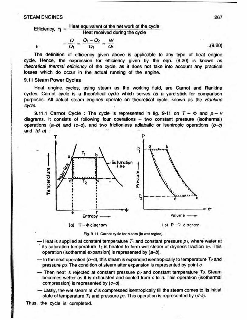
9.11.1 Carnot Cycle : The cycle is represented in fig. 9-11 on T - O and p - v diagrams. It consists of following four operations - two constant pressure (isothermal) operations (a-b) and (c-d), and two frictionless adiabatic or isentropic operations (b~c) and (d-a) :
T P
Volume
(a) T —4> diagram ( b) P —V diagram
Fig. 9-11. Carnot cycle for steam (in wet region).
— Heat is supplied at constant temperature Ti and constant pressure pu where water at its saturation temperature Ti is heated to form wet steam of dryness fraction xi. This operation (isothermal expansion) is represented by (a-b).
— In the next operation (b-c), this steam is expanded isentropically to temperature T? and pressure pz The condition of steam after expansion is represented by point c.
— Then heat is rejected at constant pressure p2 and constant temperature T?. Steam becomes wetter as it is exhausted and cooled from c to of. This operation (isothermal compression) is represented by (o-d).
— Lastly, the wet steam at d is compressed isentropically till the steam comes to its initial state of temperature Ti and pressure pi. This operation is represented by (d-a).
Thus, the cycle is completed.
Referring to the T - <X> diagram of fig. 9-11(a), heat supplied at constant temperature Ti during (a-b) is represented by area a-b-f-e and is equal to Ti (<&b-®a) or Ti (<t>c -
The amount of heat rejected (c-d) at constant temperature T? is represented byarea c-d-e-f and is equal to T2
As there is no exchange of heat during isentropic operations (b-c) and (d-a),Net work done = heat supplied during operation (a-b) - heat rejected during operation (c-d)
- Ti (4>c-<I>d) - T2 (4 > c-<M - (Ti - T2) (4>c-^d ).
~ work done (Ti - T2) (<t>c- <Dd) Ty-Tz ..(9.21)Efficiency of the Camot cycle = - — . ----- 5- 3 " — ^ —3 heat supplied T\ (Oc - <&d) Ty
Although Camot cycle is thermodynamically simple, yet it is extremely difficult to operate in practice, because the isothermal compression (c-d) must be stopped at d, so that subsequent isentropic compression (d-a) restores the fluid to its initial state a
If superheated steam is used, the cyde would be still more difficult to operate in practice, owing to the necessity of supplying the superheat at constant temperature instead of constant pressure, as it is customary. In a practical cycle, limits of pressure and volume are far more easily realised than limits of temperature so that no practical engine operates on the Carnot cycle, although all modern cycles aspire to achieve it as it is more efficient than Rankine cyde. So it is an ideal cycle for comparison purposes.
9.11.2 Rankine Cycle : In a steam plant, the supply of heat and rejection of heat is more easily performed at constant pressure than at constant temperature, and although engines have operated on this principle since the time of Watt, yet it was not until 1844, that an attempt was made by Rankine to calculate the maximum possible work that could be developed by an engine using dry saturated steam, between the pressurelimits of the boiler and the condenser. Two years later, Clausius developed a moregeneral expression for the maximum thermal effidency of a steam engine by allowing for the steam being wet initially.
The ideal Rankine cyde is used as a yard stick for the determination of the best performance obtainable in a simple steam engine cyde operating under the specific steam pressure.
Rankine cycle is a modified Carnot cyde. Except for the isentropic compression(d-a) on the Carnot cycle (fig. 9-11), theRankine and Camot cycle, are the same.
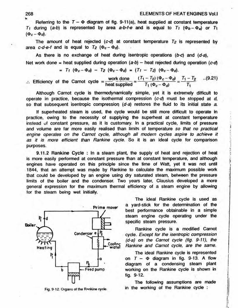
The ideal Rankine cycle is represented on T - O diagram in fig. 9-13. A flow diagram of a condensing steam plant working on the Rankine cyde is shown in fig. 9-12.
The following assumptions are made in the working of the Rankine cyde :
268 ELEMENTS OF HEAT ENGINES Vol.l
Prime mover

STEAM ENGINES 269
— The working fluid (water) is pumped into the boiler, evaporated into steam in the boiler, expanded in the prime-mover (steam engine or steam turbine), condensed in the condenser and returned to the feed pump and circulated again in a closed circuit.
— Heat is added only in the boiler and is rejected only in the condenser. There is no transfer of heat between the working fluid and the surroundings at any place except the boiler and the condenser.
— There is no pressure drop in the piping system.— Expansion in the prime-mover occurs without friction or heat transfer, i.e. the expansion
is isentropic, in which case the entropy of the working fluid entering and leaving the prime-mover is same.
— The working fluid (water) is not undercooled in the condenser, i.e. temperature of the water leaving the condenser is same as the saturation temperature corresponding to the exhaust pressure.
In the Rankine cycle, we commence with one kilogram of water at the lowertemperature and pressure 7? and P2 respectively as shown at point a in fig. 9-13. The pressure of the water is then raised to 'pi by frictionless. adiabatic compression (a-b) in the feed pump. The in-crease in temperature consequent on this compression may 4be of the order of a few degrees, and is represented by vertical line (a-b) on T - O diagram. From b to c the liquid receives sensible heat at constant pressure p i (tempera-ture increases to Ti) to be followed by evaporation at constant pressure pi, which may be partial at d (i.e. wet steam) or complete at d ' (i.e. dry saturated steam) or frequently
a superheat is imparted to raise the temperature at constant pressure p i to Tsup (which is located by point d”)
From d, d’ or d" the steam expands isentropically to e, e' or e" respectively until its pressure becomes p2 and temperature T2. The last operation (ea, e’a or e"a) is condensation at constant temperature T2 and constant pressure p2 (i.e. isothermal compression), until the working fluid is returned to its original state at a.
The process abc has been greatly exaggerated on the 7 - 0 diagram (fig. 9-13) to illustrate the process. If plotted actually, it is difficult to differentiate between abc and ac (along the water line), and in normal practice, it is assumed to be ac.
During the operation of the cycle, heat is added in the boiler, the work is performed in the prime-mover (steam engine), heat is rejected in the condenser, and the work is done on water as it passes through the feed pump. The heat equivalent of work done in pumping feed-water into the boiler is so small that it is usually neglected, i.e. triangular strip abc in the liquid region is neglected.
.j. 9-13. T-<1> diagram of Rankine cycle using wet, dry saturated, and superheated steam (steam is wet at d, dry saturated and d'and
superheated d").

270 ELEMENTS OF HEAT ENGINES Vol.l
Let Hi = Enthalpy of steam at pressure pr as it enters the prime-mover at condition d, d ’or d”.
H2 = Enthalpy of steam at pressure p2 as it leaves the prime-mover at condition e, e 'or e", and
h2 = Enthalpy of water at pressure p2 as it enters the feed pump at condition a.Work done by the prime-mover supplied with wet steam (at condition d)
= Hd - He = H1 - H2 kJ per kg of steam.Heat rejected in the condenser = He - Ha *= H2 - h2 kJ per kg of steam.
Heat supplied = work done + heat rejected= {H1 - H2) + (H2 - h£ ■ Hi - h2 kJ per kg of steam.
_ . . .. _ ,. . Work done in kJ per kg of steamEfficiency of the Rankine cycle = —— -------; — f — — ----------------7 7 Heat supplied in kJ per kg of steam
H i-H z(9.22)HA-h z
From the given values of pu p2 and condition of steam before entering the prime-mover (at point d), the condition of steam after isentropic expansion d-e at point e (fig. 9-13) is evaluted by equating entropies at d and e and using entropy values from steam tables or can be directly obtained from H — <t> chart by drawing vertical line as shown in fig. 9-21.
The Rankine cycle, ignoring the effect of feed pump work, is represented bn p - v diagram in fig. 9-14. The work done per cycle is given by area a-b-c-d. This area can be divided in three parts viz. work done by steam during admission (b-c) work done by steam during isentropic expansion (c-d), and work done on the steam during exhaust (d-a). Thus,
Work done by steam on the piston during admission (b-d) - p iv i
Pi vi — PzVzWork done during isentropic expansion (c-d) = —
PWork done on the steam dunng
exhaust stroke (d - a) = P2V2Net work done during the cycle
PlVi - PzVzIsentropicexpansion = Pi *1 +
= (P1V1 -PzYz)
n - 1f1 +
- Pzv2
1n - 1
v(P1V1 - p2v2)
Volume ■ ■ ■—
Fig. 9-14. p - v diagram of Rankine cycle.
n - 1kJ per kg of steam -(9-23)
where p i and p2 are in kPa and viand V2 are in m /kg.The value of n can be evaluated
from equation given by Dr. Zeuner or may be taken as 1 135 for steam initially

STEAM ENGINES 271
wet and 1-3 for steam initially superheated. 1
Alternatively, the work done during isentropic expansion (c-d) can be found from the definition of non-flow adiabatic process viz.
Work done during expansion = change of internal energy during expansion = u i - U 2 = (Hy - pjV j) - (H2 ~ P2V2) = - H2 - (PiVj - p2v2) kJ per kg of steam
Net work done during the cycle = pivi + [Hi - H2 - (pivi - p2V2)] - p2v2 = H) - H2 kJ/kg (same as before).
Heat equivalent of one kW-hour « 3,600 kJ ('•' 1 kW = 1 kJ/sec.)Work done per kg of steam in Rankine engine - H i - H2 kJ
Heat equivalent of one kW-hour in kJSteam consumption = — ---------- .— — r~ r~,—Work done per kg of steam in kJ3,600 . . . . . . .. (9.24)= —77- kg per kW-hour 7
- Hz
9.11.3 Modified Rankine Cycle : In practice, it is not economical to expand the steam to the extreme toe of the p-v diagram, which is represented by the point d (fig. 9-15). It is obvious that the diagram is very narrow at the toe. For this reason, the expansion is terminated (stopped) at point e and the cylinder is connected either to the atmosphere or to the condenser through exhaust port. Steam rushes out of the cylinder, causing drop in pressure upto the exhaust pressure. The expansion of the steam is thus completed by the constant volume line e-f as shown in fig. 9-15(a).
The loss of work due to incomplete expansion is represented by the area e-f-d. This cutting-off the toe occurs in reciprocating steam engine cylinder where the piston stroke is limited. In fact, the extra woik (area e-f-d) obtained by complete expansion is not sufficient to overcome the friction of the moving parts of the engine.
( a ) P -V d iag ram T (b ) T-4> d ia g ra m *Fig. 9-15. Modified ftankine cycle.
The constant volume expansion e-f after the end of isentropic expansion c-e can be represented on the T - 4> diagram as shown in fig. 9-15(b) by considering it as partial condensation. There will, therefore, be a reduction in dryness fraction during the operation e-f.

As the value of specific volume of steam at point e is known, the value of dryness fraction for any other pressure between e and f may be calculated.
The work done during the modified Rankine cyde shown in fig. 9-15(a), may be calculated from the area a-b-c-e-f of the p-v diagram.
Let pi, vi, H i and ui apply to initial condition of steam at c.P2, V2, H2 and U2 apply to condition of steam at e, andP3, hs apply to condition of water at a,
Then, work done during cycle per kg of steam■ area a-b-c-e-f of fig. 9-15(a)■ area b-c-g-o plus area c-e-h-g minus are a-f-h-o= Work done during admission (b-dj plus work done during isentropic expansion
(c-e) minus work done during exhaust (f-a)PM -Pzvz
= P1^1 + — n _ \ ~ P3V2
Alternatively, writing the work done during isentropic expansion c-e as ui - U2, i.e. change of internal energy,
Work done during cyde per kg of steam
272 ELEMENTS OF HEAT ENGINES Vol.!
= piVi + (U1 - ui) - p3v2 kJwhere p i and pa are in kPa, and v* and v2
are in m /kgHeat supplied per kg of steam = Hi - h3 kJModified Rankine cyde efficiency,
Work done during cycle in kJ per kg of steam Heat supplied in kJ per kg of steam
\T P\Vy + (Uy - Ud - P3V2 .. (9.25)
Fig. 9-16 . p-v diagram of the modified Rankine cycle. Alternatively, referring to fig. 9-16, Workdone during cyde per kg of steam
= area a-b-c-d-e-f = area b-c-e-k plus area k-e-f-a- (Hc - He) + [(pe - pH ve] kJ/kg ..(9.26a)
where p& = Pressure at release in kPa, pt = Back pressure in kPa,Hc m Enthalpy of steam at inlet (before isentropic expansion) in kJ/kg,He = Enthalpy of steam after isentropic expansion in kJ/kg, andve m Volume occupied by steam at the end of isentropic expansion i.e. at
e in m3/kg.Heat supplied per kg of steam = Hc - ha kJ/kgwhere ha = enthalpy (sensible heat) of 1 kg of water of exhaust steam (condensate) in kJ/kg.

STEAM ENGINES 273
Efficiency of modified Rankine cycle = Work done perkg of steam in kJ Heat supplied per kg of steam in kJ(He - He) + (p© - pi) ve
Hc- h a(9.26b)
9.11.4 Relative Efficiency : The relative efficiency of a steam engine is the ratio between the indicated thermal efficiency and Rankine cycle efficiency operating between the same pressure limits. It is also known as efficiency ratio.
H1- H 2Rankine cycle efficiency = HA-hz [from eqn. (9.22)]
■h. „ . . Indicated thermal efficiencyThus, Relative efficiency = —=—rr—— -;— ------1 Rankine Cycle efficiency.. (9.27)
When brake thermal efficiency is used instead of indicated thermal efficiency in eqn. (9.27), the efficiency is termed overall efficiency ratio.
The efficiency ratio for a given steam engine indicates the percentage of the available heat converted into mechanical work. It also provides a measure of the excellence of design of the steam engine for the steam, conditions under which it is operating and of its mechanical condition.Problem-19 : A Carnot engine receives dry saturated steam at 35 bar (3,500 kPa)and exhausts at 0 7 bar (70 kPa). Calculate : (a) the heat supplied per kg of steam,(b) the heat rejected per kg of steam, (c) the maximum work obtained per kg of steam,and (d) the Carnot cycle efficiency.
From steam tables :
p ts <*>» !bar *c KJ/kg K kJ/kg K j
35 2426 2-7253 6-1253
0-7 8995 — —
Ti =
3Oi—OfCL
e
H E I - 18
242 6 + 273 = 5156 K; T2 = 89 95 + 273 = 362 95 K
Entropy --
(a) T-4> diagramFig. 9-17.
Volume —
(b) P -V diagram

274
Referring to fig. 9-17(a),(a) Heat supplied - T i (<Db - Oa) = 515-6(6-1253 - 2-7253) = 1,753 04 kJ/kg
(b) Heat rejected = T2 (<DC-< M= 362 95 (6-1253 - 2-7253) [ vO c = 0>b and 0d=0>a)- 362 95 x 34 = 1,234 03 kJ/kg.
(c) Work obtained = Heat supplied - Heat rejected= 1,753 04 - 1,23403 = 519 01 kJ/kg
(d) Camot cycle efficiency or thermal efficiency
= Wojkdon|p5r kg. _ 5J|£L „ 0 2961 „ 2961%Heat supplied per kg 1,753-04
Alternatively, using eqn. (9.21), Camot cycle efficiency
h - T2 515-6 - 362-95
ELEMENTS OF HEAT ENGINES Vol.l
5156= 0-2961 or 29-61% (same as before)
Problem-20 : A steam power plant is supplied with dry saturated steam at a pressure of 14 bar and exhausts into a condenser at a pressure of 0-3 bar. Using the steam tables, calculate the efficiency of Camot cycle and Rankine cycle for these conditions. Draw T - 4> diagrams for the cycles.From steam tables :
p bar 4 ’C h kJ/kg L kJ/kg H kJ/kg d>w kJ/kg K kJ/kg K
14 195-07 — — 2,790 — 6 4693
0 3 6910 289 23 2,3361 — 0-9439 7-7686
Carnot cycle : Ti = 195-07 + 273 * 468 07 K, T2 m 69-1 + 273 = 342-1 K Referring to fig. 9-18 (a) and using eqn. (9 21),
Carnot cycle efficiency = = 0 2691 or 26 91%T 1 t
Entropy —
(a) Carnot cycle Fig. 9-18.
Entropy --
(b) Rankine cycle

STEAM ENGINES 275
Rankine cycle : Referring to fig. 9*18 (b) and considering isentropic expansion c-d. Entropy at c = Entropy at d i.e. <J>Sc = ®wd+ xd {<&sd - <l>wd)
i.e. 6-4693 = 0-9439 + Xd (7-7686 - 0 9439) .-. Xd = 0-81Htf = hd + XdLd = 289-23 + 0-81 x 2,336-1 = 2,181-47 kJ/kg.Hc = 2,790 kJ/kg (from steam tables).Work done - Hc - Hd - 2,790 - 2,181-47 « 608-53 kJ/kg. .Heat supplied = Hc — ha = 2,790 - 289-23 = 2,500-77 kJ/kg.Using eqn. (9.22), Rankine cycle efficiency
j ^ d o n e l^ je r k g _ _60853_ _ 2433%heat supplied in kJ per kg 2,500-77
Alternatively, the value of xd and Hc - Hd can be directly obtained from H - <t>chart by drawing vertical line from the point on dry saturated line intersected by 14 bar line, to meet the line of 0-3 bar. The method of finding out xd and Hc - Hd from H - O chart is shown in fig. 9-21. Hence, the Rankine cycle efficiency.
It may be noted that the Carnot cycle is more efficient than Rankine cycle.Problem-21 : In a Carnot cycle the upper and lower limits of temperature correspond to steam pressures of 28 bar and 0-15 bar respectively. Dry saturated steam is supplied to the engine. Evaluate : (a) the dryness fraction of steam at the begining of isentropiccompression, (b) the work done per kg of steam, (c) the heat supplied per kg of steam,and (d) the Carnot cycle efficiency. Compare items (b), (c) and (d) with the corresponding figures obtained for an engine working on the Rankine cyde between the same limits of pressure and temperature.From steam tables :i p bar t ’C h kJ/kg L kJ/kg H kJ/kg 4>w kJ/kg K <S>a kJ/kg K
28 230 1 990 59 — 2,804 2 6109 62139015 53 97 225 94 2,373-1 — 0-7549 8-0085

276 ELEMENTS OF HEAT ENGINES Vol.l
Carnot cycle : (a) Ti - 230-1 + 273 = 503-1 K; T2 - 53 97 + 273 - 326-97 K Referring to T-<D diagram of fig. 9-19(a) and considering isentropic compression d-a Entropy at a = Entropy at d i.e. <J>wa = Q>wd + xd (<&sd- <t>wd)
i.e. 2 6109 = 07549 + xd (80085 - 0-7549) Xd = 0 256(b) Work done = (Ti - Ti) (<& sc — Qm/}
= (T1 ~ T2) (Qsb-®wa)= (503-1 - 326-97) ( 6-2139 - 2 6109) = 634 6 kJ/kg.
(c) Heat supplied = Hb - ha = 2,804 - 990 59 = 1,81341 kJ/kg
(d) Carnot cycle efficiency = - ^ ? r—— x 100 = 35%' ' J heat supplied 1,813-41Alternatively.; using eqn. (9.21),
Carnot cycle efficiency = — ■ _ — = ̂ 326 97 x -jqq _ 35% (same as before)#1 503-1
Rankine cycle :(b) Referring to fig. 9-19(b), Entropy at b « Entropy at c
i.e. Osb = ®wc ^c(®sc- ®i«^ i.e. 6-2139 = 0-7549 + xc (80085 - 0-7549)/. xc = 0-753 (dryness fraction at c)
Now, Hc - hc + XcLc - 225-94 + 0 753 x 2,373-1 = 2,01288 kJ/kgWork done » Hb - Hc m 2,804 - 2,012-88 = 791-12 kJ/kg of steam.(c) Heat supplied = Hb — hd = 2,804 — 225-94 = 2,578 06 kJ/kg of steam.,JV „ • work done in kJ/kg 791-12(d) Rankine cycle efficiency = —•— ---------------------------- - x 100 = 30 7%v ' 1 1 heat supplied in kJ/kg 2,578 06 .
Problem-22 : Steam at 14 bar and 315'C is supplied to an engine working on theRankine cycle. The steam is exhausted at 007 bar. Draw the T - O and p - vdiagrams for the cycle and calculate using the steam tables : (a) the condition of steam after isentropic expansion, (b) the Rankine cycle efficiency, (c) the mean effective pressure, (d) the ideal steam consumption per kW hour, and (e) the actual steam consumption per kW hour of the engine if the relative efficiency is 06. Take kp for superheated steam as 21 kJ/kg K.
From steam tables, at 14 bar, H = 2,790 kJ/kg, <J>S = 6-4693 kJ/kg K, i95 07"C,and at 007 bar, h = 163 4 kJ/kg, L = 2,409-1 kJ/kg, vs = 20-53 m3/kg, <t>w = 0-5592kJ/kg K and <PS = 8-2758 kJ/kg K.
(a) Referring to T-O diagram of fig. 9-20 and considering isentropic expansion c-d,Entropy at c = Entropy at d
i.e. <t>sc + kp \oge
i.e. 6-4693 + 2-1 log®
f t '' supc Tsatc\^_315 + 273 195 07 + 273
— ®wd + xd(®sd~
= 0-5592 + Xd (82758 -0-5592) Xd - 0 828

STEAM ENGINES Xd
P
0828 277
(a) T-<£ diagram ( b) I3*'*’ diagramPig. 9-20. Rankine cycle diagrams.
(b) Hc = 2,790 + 2-1 (315 - 19507) - 3,041-85 kJ/kg.Hd = 163-4 + 0-828 x 2,409-1 = 2,158 kJ/kgha = 163-4 kJ/kg (from steam tables.).Work done = Hc - Hd = 3,041-85 - 2,158 m 883 85 kJ/kg.
Heat supplied ^ Hc - ha = 3,041-85 - 163-4 = 2,878-45 kJ/kgNow, Rankine cycle efficiency,
work done in kJ per kg _ 883-85 10Q _ 3q 7o/~ heat supplied in kJ per kg " 2,878-45 x ~ °
(c) Specific volume, vs at 0-07 bar = 20 53 m3/kg (from steam tables), Volume, vd * Xd x vs = 0-828 x 20-53 m3/kg.
Mean effective pressure =_ work done in kJ or kN.m per kg of steamstroke volume in m per kg of steam (vd)
88385 = 52 kPa or 52 kN/m‘0-828 x 20 53(d) Work done in Rankine cycle = Hc - Hd = 3,041-85 - 2,158 = 883-85 kJ/kg.Using eqn. (9.24) ideal steam consumption in kg per kW-hr.
_ Heat equivalent of one kW-hr. _ 1 x 3,600 _ 3J>00. n__ . . w .hrWork done per kg of steam * Hc- Hd ~ 883-85 " 9 Pe •
a.* ,, . _ . .. „. . Indicated thermal efficiency(e) Using eqn. (9.27), Relative efficiency = - = —a 1— L' 7 » i ' •' 7 Rankine cycle efficiencyIndicated thermal efficiency, r\j = 0-6 x 0-307 = 0-1842 or 18-42%
. .. , . . Heat equivalent of one kW-hr in kJIndicated thermal efficiency, m = -------- . / T r r -----------1 1 Ms (Hc- ha) in kJ(where Ms is the actual steam consumption in kg per kW-hr.)

278 ELEMENTS OF HEAT ENGINES Vol.l
I.e. 0-1842 =
Alternatively, Ms =
1 x 3,600Ms x (3,041-85-163-4)
1 x 3,6000-1842 x (3,041-85-163 4) - 6 79 kg per kW-hr.-
4-0780-6
= 6-79 kg per kW-hr.(same as before)
Problem-23 : A steam engine is supplied with dry saturated steam at 7 bar and exhausts at 14 bar. The steam consumption was found to be 2 kg per minute when developing indicated. power of 4 5 kW. Using the steam tables or H - <D chart, find the relative efficiency.
From steam tables, at 7 bar, H = 2,763-5 kJ/kg, 4>s = 6-7080 kJ/kg K; and at1-4 bar, h - 458-39 kJ/kg, L = 2,232-1 kJ/kg, <DW = 14109 kJ/kg K and d>s = 7-2464 kJ/kg K.
, .. . . .. . . Heat equivalent of indicated power in kJ per sec.Indicated thermal efficiency, t i / = ------------ —----------------- - .----------------------7 1 Net heat supplied in kJ per sec.kW or kJ sec. ms (Wt - hz)
45
(2,763 5 - 458-39)= 0-0587 or 5-87%
60H
>-aoXTiS
•4»
Fig. 9-21. Isentropic heat drop, H \ - h k from H-Q> chart.
In order to determine the relative efficiency or efficiency ratio, it is first necessary to determine the Rankine cycle efficiency operating between same pressure limits, i.e. 7 bar and 1-4 bar.
Using the steam tables and considering isentropic expansion 1 - 2, as shown in fig. 9-21,
Entropy before expansion, Oi= Entropy after expansion, <J>2
Os1 = Ow2 + X2 (Os2 - Q>WZ)
i.e. 6-7080 = 1-4109 + X2 (7 2464 - 1 4109)X2 - 0-908
Thus, enthalpy after isentropic expansion, H2 = h2 + X2L2
= 458 39 + 0-908 x 2,232-1 = 2,485 14 kJ/kg
Enthalpy before isentropic expansion, Hi = 2,763-5 kJ/kg.Isentropic enthalpy drop = Work done
= Hi - H2 m 2,763-5 - 2,485 14 = 278-36 kJ/kg of steam.Alternatively, the value of Hi - H2 (isentropic enthalpy drop) can be directly obtained
from H - <P chart by drawing vertical line 1-2 from point on saturation line intersected by 7 bar line, to meet line of 1-4 bar as shown in fig. 9-21.
Heat supplied = Hi - h2 - 2,763 5 - 458 39 = 2,305 1 kJ/kg of steam.
Rankine cycle efficiency =Work done in kJ per kg of steam
Heat supplied in kJ per kg of steam

STEAM ENGINES 279
Hi - H2 278 36= 012077 or 12 077%H , -h z 2,305-1
Using eqn. (9.27), Relative efficiency or efficiency ratio_ Indicated thermal efficiency _ 0-0587 _ 0486 or 48 g0/
Rankine cycle efficiency ~ 0-12077 ~ 0Problem-24 : In a modified Rankine cycle steam is supplied at 55 bar and 190'C. It expands isentropically to 2-8 bar when it is released at constant volume to exhaust pressure of 1 bar.
Using the steam tables only, determine : (a) the work done per kg of steam supplied, (d) the modified Rankine cycle efficiency, (c) the ideal steam consumption per kW-hr and (d) the volume of steam to be supplied per kW-hr. Take kp of superheated steam as 2-1 kJ/kg K.
From steam tables, at 5-5 bar, <J>S = 6-7893 kJ/kg K, H - 2,753-0 kJ/kg, vs = 0-3427 m3/kg, ts = 155-48'C; at 2 8 bar, <DW = 1-6472 kJ/kg K, <DS = 7 0149 kJ/kg K, h = 551 48 kJ/kg, L = 2,170 7 kJ/kg, vs = 0 6463 m3/kg, and at 1 bar, h = 417-46 kJ/kg.
(a) Referring to fig. 9-22, and considering isentropic expansion c-e,Entropy at c = Entropy at e
i.e. 6-7893 + 2-1 loge 190 + 273155-48 + 273
= 1-6472 + x0 (7-0149 - 1-6472) /. xg = 0-988 (dryness fraction at e) Now, Hc m 2,753 + 2-1 (190 - 155-48)
= 2,825-5 kJ/kg Hq — hg + XqLq
m 551 48 + 0-988 x 2,170 7 = 2,696 kJ/kg
V ve = Xg X Vs
= 0-988 x 0-6463 = 0-6385 m3/kg.
Using eqn. (9.26a), work done = (Hc - He) + [{pe - pi) ve]= 2,825-5 - 2,696) + [(280 - 100) 0 6385]= 244-43 kJ/kg of steam
Heat supplied = Hc - ha = 2,825-5 - 417-46 = 2,408-04 kJ/kg of steam.(b) Using eqn. (9.26b), Modified Rankine cycle efficiency
= = _ of heat supplied in kJ per kg of steam 2408 04
(c) Using eqn. (9.24), Ideal steam consumption per kW-hourheat equivalent of one kW -hour 3,600
Work done per kg of steam 24443 = 14-73 kg per kW-hr.

280 ELEMENTS OF HEAT ENGINES Vol.l
(d) Volume of 1 kg of superheated steam at 5-5 bar and 190‘C
190 + 273v'sup = vs * - y f{ = 0-3427 x 155-48 + 273 = 0 3703 m3/kg
Volume of steam supplied = 14 73 x 03703 = 5-4545 m3 per kW-hr.Problem-25 : A steam engine is supplied with dry saturated steam at a pressure of 14 bar (14 MPa). Pressure at release is 06 bar (60 kPa) and exhaust takes place at 015 bar (15 kPa). Assuming isentropic expansion with constant volume conditions between release and commencement of exhaust, determine using steam tables only, (a) the work done per kg of steam (b) the mean effective pressure, and (c) the efficiency of the cycle.
Compare these values with those for Rankine cyde between the same pressure limits.
From steam tables :
pbar
v$m3/kg
hkJ/kg
LkJ/kg
HkJ/kg kJ/kg K kJ/kg K
14 0 — — •— 2,790 — 64693
0 6 2-732 359 86 2,293 6 — 11453 7-532
015 10-022 225 94 2,373-1 — 0-7549 80085
Isentropic
(a) Referring to fig. 9-23, and considering isentropic expansion 1-2 from 14 bar to- 0-6 bar and then release at constant Volume 2-4
Irom 0-6 bar to 0-15 bar (modified Rankine cyde) :Considering isentropic expansion 1 - 2 ,
Os1 = <$W2 + X2 (<E>s2 -
i.e. 6 4693 = 1-1453 + X2 (7-532 - 1-1453).*. X2 = 0-834
From steam tables, Hi = 2,790 kJ/kg;H2 — h2 + x2L2
= 359 86 + 0-834 x 2,293-6 = 2,272-72 kJ/kgSpecific volume at 0-6 bar * 2-732 m3/kg
Volume ----- m* (from steam tables).Fig. 9-23. Volume v2 = x2Vs2 = 0-834 x 2-732 m3/kg = v4
Using eqn. (9.26a), work done per kg of steam in modified Rankine cyde= (Hi - H2) + [{p2 - p4) v2]= (2790 - 227272) + [(60 - 15) x 0-834 x 2-732 ]= 620 35 kJ/kg of steam or = 6,20,350 N.m/kg of steam
Work done per of steam in N.m(b) Mean effective pressure =Stroke volume in m per kg of steam (v4)
6,20,3506,20,350 m/^2 _ /q _\N/m or (Pa)= — c 0 834 x 2 732 105 x 0-834 x 2 732
= 2 72 bar
( v 1 bar = 105 Pa)

STEAM ENGINES 281
/ v I . j x- . r-. . • , ■ Work done per kg of steam in k j(c) Modified Rankine cycle efficiency = - r ----- »— — ;—r -r' Heat supplied per kg of steam in kJWork done 62035 - 0-2419 or 2419%H, -/>3 2,790-225 95
Considering Rankine cyde :(a) Referring to fig. 9-23, and considering complete isentropic expansion 1-3 from
14 bar to 0-15 bar,
* s i = + *3 (^ s3 - ^w s)
i.e. 6-4693 - 0-7549 + X3 (8 0085 - 0 7549) X3 = 0788 Now, Hi ■ 2,790 kJ/kg (steam tables), and
H3 = h3 + x3 L3 = 225-94 + 0788 x 2,373-1 = 2,095-94 kJ/kg Work done « Hi « Hs - 2,790 - 2,095 94 = 69406 kJ/kg.
= 6,94,060 N.m/kg of steam.Work done in N.m per kg of steam
stroke volume in m3 per kg of steam (V3)6,94,060
(b) Mean effective pressure =
6,94,0600 788 x 10-022 N.m or =
10s x 0*788x10 022= 0879 bar ( v i bar = 10s N/m2)
. . _ .. . . Work done per kg of steam in kJ(c) Rankine cycle efficiency = - — :-------,r~V — , — — ------—t t' ' 7 Heat supplied per kg of steam in kJH , - H 3 69406 x 100 = 27 07%H^-hs 2,790 - 225-94
Problem-26 : An engine is supplied with dry saturated steam at 8-5 bar. Expansion is earned out at constant entropy to a pressure of 1 bar (100 kPa) and the exhaust pressure is 015 bar (15 kPa). Sketch the ideal p - v and T - <P diagrams for the cycle and indicate there on the work done and the condition of steam at exhaust. Using the steam tables only, find the work done per kg of steam, the modified Rankine cyde efficiency, and the index of expansion.
Taking the Rankine cycle as standard, find the percentage loss of efficiency due the incomplete expansion.
pbar O)
|
hkJ/kg
LkJ/kg
HkJ/kg
4>w kJ/kg K kJ/kg K
85 0-227 — — 2.771 6 — 6-6421t 1 694 41746 2,258 — 1 3026 7 3594
0 15 — 225 94 2,3731 — 07549 80085
Considering modified Rankine cycle :Referring to fig. 9-24(a) and considering isentropic expansion c-e.
Entropy at c = Entropy at e i.e. 6-6421 * 1-3026 + x©(7-3594 - 1 3026) xe = 0 882 (dryness fraction at e) v0 = xg x Vse = 0-822 x 1-694 = 1-5 m3/kg; vc = 0 227 m3/kg (from steam tables) /. He = he + XgLe = 417-46 + 0-882 x 2,258 = 2,409 kJ/kg

282 ELEMENTS OF HEAT ENGINES Vol.l
(a ) T - <fc> diogrpm (b) diagramFig. 9-24. Modified Rankine cycle.
Hc * 2,771-6 kJ/kg and ha = 225-94 kJ/kg (from 'steam tables) Using eqn. (9.26a), Work* done in modified Rankine cycle
= (Hc ~ He) + [(pe - pfim (2,771 6 - 2,409) + 1(100 - 15) 1-5] - 4901 kJ/kg.
Heat supplied = Hc - ha - 2,771 6 - 225-94 = 2,545-66 kJ/kg.Modified Rankine cycle efficiency,
JWorkdone in kJ/kg _ 490-1Heat supplied in kJ/kg = 01925 or 19 25%2,54566
The isentropic expansion c-e of fig. 9-24 (b) is represented by equation p>P C.
Now, peven m pcvcn i.e. — =f \n
Vc
n =log
r n \PcPe log r8-5>
1
logVc \ V
logV
1-5 j 0-227/
= 1 134
Considering Rankine cycle :j?Referring to fig. 9-24(a) and considering isentropic expansion c-d.
Entropy at c = Entropy at di.e. 66421 ■ 0-7549 + xd (8-0085 - 0-7549) xd * 0-812 (dryness fraction at d) Now, Hd = hd + XdLd = 225-94 + 0-812 x 2,373-1 - 2,152-9 kJ/kg
Hc = 2,771 6 kJ/kg and ha = 225-94 kJ/kg (from steam tables).Work done = Hc - Hd - 2,771-6 - 2,1529 = 618-7 kJ/kg Heat supplied = Hc — ha = 2,771-6 — 225-94 = 2,545-66 kJ/kg
Rankine cvcle effidencv = - W o* done InkJ/Kg, _6187_ 24 3%HanKine cycle emcieney - Heatsupp|jedjnkJ/k9 2,545-66 u ‘ ' o u l
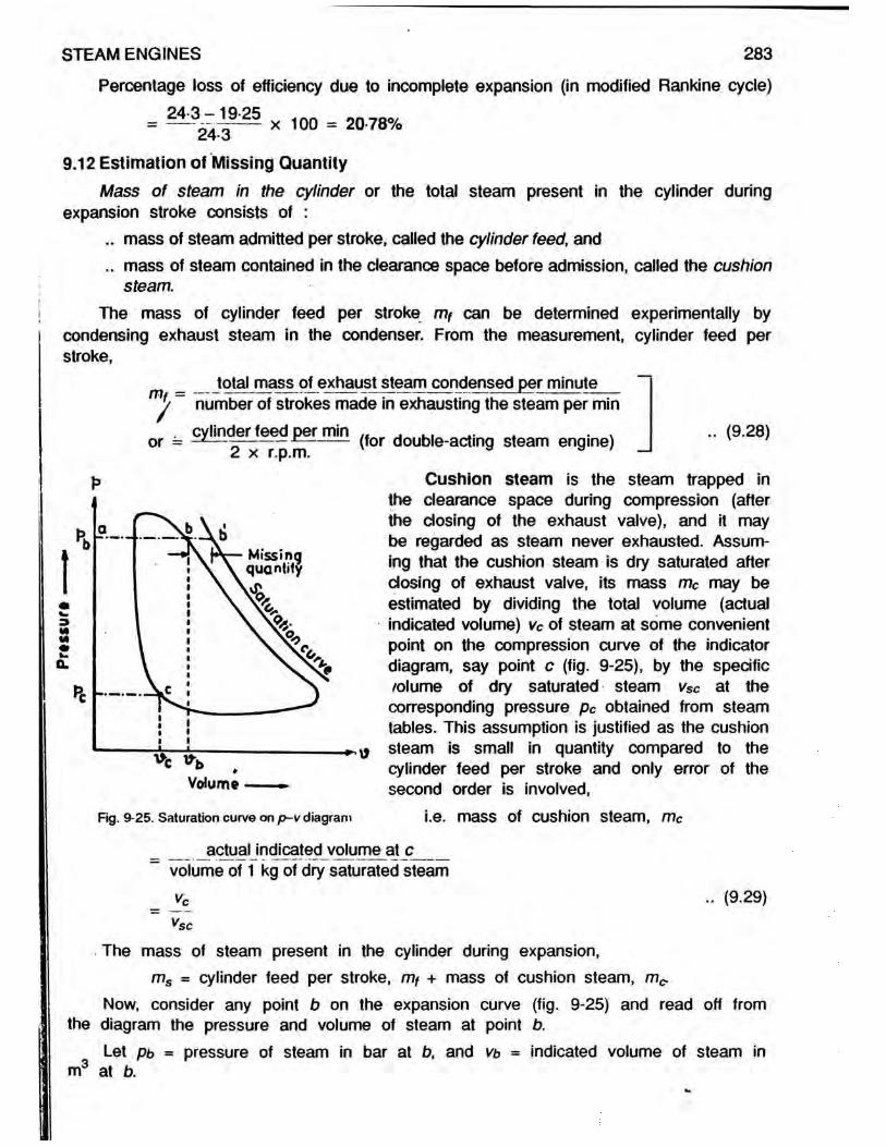
STEAM ENGINES 283
Percentage loss of efficiency due to incomplete expansion (in modified Rankine cycle) 24-3-19-25
24-3 x 100 = 20-78%
9.12 Estimation of Missing QuantityMass of steam in the cylinder or the total steam present in the cylinder during
expansion stroke consists of :.. mass of steam admitted per stroke, called the cylinder feed, and.. mass of steam contained in the clearance space before admission, called the cushion
steam.The mass of cylinder feed per stroke mf can be determined experimentally by
condensing exhaust steam in the condenser. From the measurement, cylinder feed per stroke,
_ _ total mass of exhaust steam condensed per minute m% ~ number of strokes made in exhausting the steam per min
or = g^ jnt̂ erj ^ d per min ^Qr d0Ubie-acting steam engine) _ (9.28)
Fig. 9-25. Saturation curve on p-v diagram
actual indicated volume at c___volume of 1 kg of dry saturated steam
Cushion steam is the steam trapped in the clearance space during compression (after the dosing of the exhaust valve), and it may be regarded as steam never exhausted. Assum-ing that the cushion steam is dry saturated after closing of exhaust valve, its mass mc may be estimated by dividing the total volume (actual indicated volume) vc of steam at some convenient point on the compression curve of the indicator diagram, say point c (fig. 9-25), by the specific volume of dry saturated steam vSc at the corresponding pressure pc obtained from steam tables. This assumption is justified as the cushion steam is small in quantity compared to the cylinder feed per stroke and only error of the second order is involved,
i.e. mass of cushion steam, mc
(9.29)rsc
The mass of steam present in the cylinder during expansion,ms = cylinder feed per stroke, mf + mass of cushion steam, m^
Now, consider any point b on the expansion curve (fig. 9-25) and read off from the diagram the pressure and volume of steam at point b.
Let pb ■ pressure of steam in bar at b, and vt> = indicated volume of steam in m3 at b.

284 ELEMENTS OF HEAT ENGINES Vol.l
From steam tables obtain the specific volume vSb of dry saturated steam at pressurepb. Then, the volume, the steam at b would occupy if dry saturated = ms x Vsb. Thisvolume is represented by ab' to the volume scale of the indicator diagram. Thus, the point b’ represents the volume which the steam at b would occupy if it was dry saturated.
Similarly, for every point on the expansion curve, a point corresponding to dry saturated condition can be obtained. A curve drawn through all these points Is knownas the saturation curve. The saturation curve shows at a glance the wetness (drynessfraction) of steam in the cylinder and volume of the missing quantity at any part of the expansion stroke.
_ . . . . . . . actual indicated vol. at b ab vb ..(9.30)Dryness fraction of steam at b = — £— I----------.----------- = -— = -------------1 dry steam volume atf ms x vSb
The distance bb’ (fig. 9-25) is the volume of missing quantity for the point b.It may be noticed from fig. 9-25 that the steam is wet at the beginning of the
expansion stroke and becomes drier towards the end of the stroke. This is due to the fact that the high pressure steam at the commencement of the expansion stroke is hotter than the cylinder walls; this causes steam to condense. The steam- pressure falls during the expansion stroke, and towards the end of the stroke the cylinder walls will be hotter than the steam; this will cause re-evaporation of condensed steam and the dryness fraction of steam will consequently increase (Refer illustrative Problem no.28).
Referring to indicator diagram of fig. 9-25, the point b' on saturation curve represents the volume, the steam would occupy, if it was dry saturated while the actual volume occupied is represented by the point b on the expansion curve. The horizontal distance between the saturation curve and expansion curve at any part of the stroke is known as missing quantity and is represented by bb’ m3 at point b. Alternatively, the missing quantity in kg per stroke may be regarded as the difference between the actual total mass of steam present in the cylinder during expansion stroke (mt + mc) and the indicated dry mass of steam at the point b.
Referring to fig. 9-25,Let pb - pressure of steam in bar at b.
vb = volume of steam (actual indicated volume) in m3 at b, and Vsb = specific volume in m /kg at pressure pb (from steam tables).
Then, indicated dry mass of steam at b
actual indicated volume in m3 at b ___specific volume in m3 of 1 kg of dry saturated steam at pressure pb
vb .. (9.31)kg
VsbThis mass is called the “indicated mass" because it is calculated by means of
data obtained from a curve drawn by an indicator.The dryness fraction of steam at b may also be expressed as
__ indicated dry mass of steam at b__________________ •• (9.32) |jtotal mass of steam present in the cylinder during expansion = ny+ me
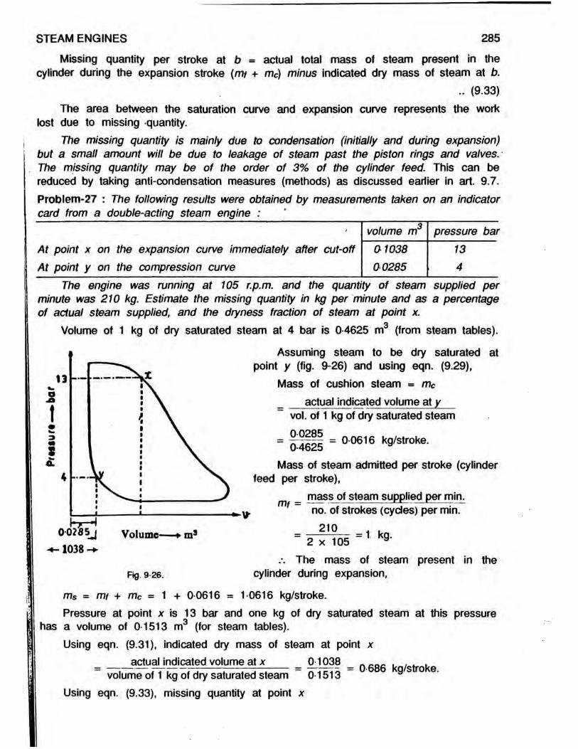
STEAM ENGINES 285
Missing quantity per stroke at b - actual total mass of steam present in the cylinder during the expansion stroke (mt + mc) minus indicated dry mass of steam at b.
.. (9.33)The area between the saturation curve and expansion curve represents the work
lost due to missing quantity.The missing quantity is mainly due to condensation (initially and during expansion)
but a small amount will be due to leakage of steam past the piston rings and valves.- The missing quantity may be of the order of 3% of the cylinder feed. This can be reduced by taking anti-condensation measures (methods) as discussed earlier in art. 9.7.Problem-27 : The following results were obtained by measurements taken on an indicator card from a double-acting steam engine :
volume m3 pressure barAt point x on the expansion curve immediately after cut-off 01038 At point y on the compression curve 00285
134
The engine was running at 105 r.p.m. and the quantity of steam supplied per minute was 210 kg. Estimate the missing quantity in kg per minute and as a percentage of actual steam supplied, and the dryness fraction of steam at point x.
Volume of 1 kg of dry saturated steam at 4 bar is 0-4625 m (from steam tables).
Assuming steam to be dry saturated at point y (fig. 9-26) and using eqn. (9.29),
Mass of cushion steam = mcactual indicated volume at y
vol. of 1 kg of dry saturated steam0028504625 = 0-0616 kg/stroke.
Mass of steam admitted per stroke (cylinder feed per stroke),
_ mass of steam supplied per min. mf ~ no. of strokes (cycles) per min.
2102 x 105 = 1 kg.
.-. The mass of steam present in the Rg. 9-26. cylinder during expansion,
ms = mt + mc = 1 + 0-0616 = 1-0616 kg/stroke.Pressure at point x is 13 bar and one kg of dry saturated steam at this pressure
has a volume of 0-1513 m3 (for steam tables).Using eqn. (9.31), indicated dry mass of steam at point x
actual indicated volume at x 01038volume of 1 kg of dry saturated steam 0-1513
Using eqn. (9.33), missing quantity at point x
= 0-686 kg/stroke.

286 ELEMENTS OF HEAT ENGINES Vol.l
= mass of steam present in the cylinder during expansion minus indicated dry mass of steam point x.
= 1 0616 — 0 686 = 0-3756 kg/stroke..*. Missing quantity/min. at point x - 0-3756 (2 x 10⁵) » 78-88 kg per min.
(engine being double-acting).Missing quantity at point x as a percentage of actual mass of steam supplied
= x 100 = 37-56%
Using eqn. (9.32), dryness fraction of steam at point x indicated dry mass of steam at point x
mass of steam present in the cylinder during expansion06861 0616 = 0 646 or 64-6% dry.
Problem-28 : The high-pressure cylinder of a double-acting steam engine running at 100 r.p.m. has an effective area of 250 errJ2 and a stroke of 60 cm and the clearance volume is 7 per cent of the stroke volume. During a trial the cylinder feed was 9 kg per minute. The indicator diagram showed that cut-off and release occurred at 30 and 90 per cent of the outward (expansion) stroke while the compression commenced at 70 per cent of the return (exhaust) stroke. The indicated pressures at cut-off, release and commencement of the compression are 14, 55 and 3 bar respectively. Find the quality of steam at cut-off and at release.
Referring to fig. 9-27, the swept volume, vs = 250 60 = 0-015 m3.104 100
Clearance volume = 0 07vs
7100 x 0 015 = 0-00105 mw
Total volume (indicated) at A (at cut-off)( 30 100
x 0-015 + 0 00105 = 0 00555 mJ
Total volume (indicated) at B (at release)90100 x 0-015 + 0 00105 = 0-01455 m3.
Total volume (indicated) at C (at commen-cement of compression)
'100-70 x 0-015
,3
+ 0-00105100
= 0-00555 mc Mass of steam admitted per stroke
(cylinder feed per stroke),
Qmf = = 0-045 kg (engine being double-acting)

The specific volume of steam at 3 bar = 0-6058 m3/kg (from steam tables).Using eqn. (9.29), the mass of cushion steam assumed to be dry saturated
per stroke._ _actual indjcated volume at poim C _ = 000655 _ 0009t6 R stroke
e volume of 1 kg of dry saturated steam 0-6058The mass of steam present in the cylinder during the expansion,ms = rrif + mc = 0-045 + 0-00916 * 0-05416 kg.
At cut-off (Point A) :Total mass of steam present in the cylinder during expansion stroke = 0-05416 kg.
The specific volume of steam at 14 bar » 0-1408 nr/kg (from steam tables). Hence,the steam if dry saturated at cut-off in the cylinder at 14 bar would have a volume of
005416 x 0-1408 = 0-00763 m3.The. total volume (actual indicated volume) of steam in the cylinder at point A (at
cut-off) is found to be 0-00555 m3.Using eqn. (9.30), quality (dryness fraction) of steam at point A (at cut-off)
actual indicated volume at A 0-00555= — --------- :------------= ■ = 0-727 or 72-7% dry.dry steam volume 0-00763At release (point B) :
Total mass of steam in the cylinder during expansion stroke = 0-05416 kg. The specific volume of steam at 5-5 bar * 0-3427 nr/kg (steam tables). Hence, the volume of steam if dry saturated at release in the cylinder at 5-5 bar = 0-05416 x 0-3427 * 0-01856 m3.
The total volume (actual indicated volume) of steam at release (at point B) in the cylinder is found to be 001455 m3.
Using eqn. (9.30), quality (dryness fraction) of steam at point B (at release)_ actual indicated volume at B _ 0-01455
drvste* 'volume - 0-01856
STEAM ENGINES 287
= 0-784 or 78-4% dry.
»*~»K0-2IM-.— o-7 v — 1 008* ^
K - V- -----Volume
Problem-29 : Determine the dryness fraction of steam and the missing quantity per hour at 07 of the expansion stroke, from the following data :
Diameter of cylinder, 40 cm; stroke, 60 cm; r.p.m., 100; cut-off at 50% of the stroke; clearance volume, 8% of swept volume; steam condensed per min., 40 kg; pressure of steam at 07 of the expansion stroke, 5 bar; pressure of steam at 08 of
1— V the return stroke on the compression curve,14 bar. State any assumptions made,
Referring to fig. 9-28, the swept volume,
Fig. 9-28.V =
K I 40 4 100
60100 = 0 0754 m
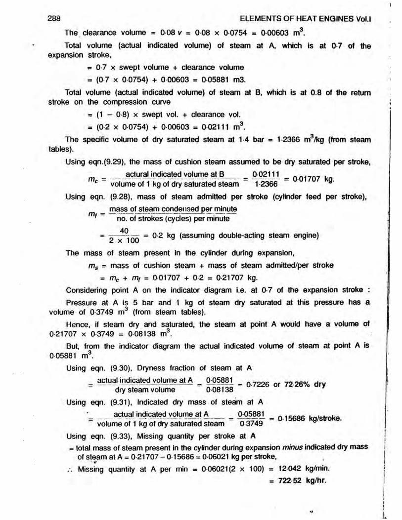
The clearance volume - 0 08 v = 0 08 x 0 0754 = 0 00603 m3.Total volume (actual indicated volume) of steam at A, which is at 0-7 of the
expansion stroke,= 0-7 x swept volume + clearance volume- (0-7 x 0 0754) + 0 00603 = 0 05881 m3.
Total volume (actual indicated volume) of steam at B, which is at 0.8 of the return stroke on the compression curve
= (1 - 0-8) x swept vol. + clearance vol.= (02 x 00754) + 0 00603 = 0 02111 m3.
The specific volume of dry saturated steam at 1-4 bar = 1-2366 m3/kg (from steamtables).
Using eqn.(9.29), the mass of cushion steam assumed to be dry saturated per stroke,actural indicated volume at B 0-02111 . . . . . . .m = — ------- — -— ~— --------= = 0-01707 kg.
volume of 1 kg of dry saturated steam 1 -2366 9Using eqn. (9.28), mass of steam admitted per stroke (cylinder feed per stroke),
_ mass of steam condensed per minute f ~ no. of strokes (cycles) per minute
40= 2 X i on = O'2 k9 (assumin9 double-acting steam engine)
The mass of steam present in the cylinder during expansion,ms = mass of cushion steam + mass of steam admitted/per stroke
= mc + mf = 0 01707 + 0 2 = 0-21707 kg.Considering point A on the indicator diagram i.e. at 0-7 of the expansion stroke :Pressure at A is 5 bar and 1 kg of steam dry saturated at this pressure has a
volume of 0-3749 m3 (from steam tables).Hence, if steam dry and saturated, the steam at point A would have a volume of
0 21707 x 0 3749 = 008138 m3.But, from the indicator diagram the actual indicated volume of steam at point A is
005881 m3.Using eqn. (9.30), Dryness fraction of steam at A
actual indicated volume at A 0-05881 _ooe _ , 0 oco/= — ---------------= ■ = 0-722o or 72-zovo arydry steam volume 0-08138Using eqn. (9.31), Indicated dry mass of steam at A
•_ actual indicated volumeat A M588J. _ 015686 kg/strokevolume of 1 kg of dry saturated steam 0-3749
Using eqn. (9.33), Missing quantity per stroke at A= total mass of steam present in the cylinder during expansion minus indicated dry mass
of steam at A = 0-21707 - 0-15686 = 0-06021 kg per stroke,Missing quantity at A per min = 0-06021(2 x 100) = 12-042 kg/min.
■ 722 52 kg/hr.
288 ELEMENTS OF HEAT ENGINES Vol.l

Alternatively, using eqn. (9.32), j Dryness fraction of steam at A 1 _ indicated dry mass of steam at A
STEAM ENGINES 289
| i.e. at 0-7 of the expansion stroke j [mass of steam present in theI cylinder during expansion I
015686 = 07726 or 7726% (same as before)021707Problem-30 : A double-acting steam engine, having a diameter of 70 cm and stroke 120 cm runs at 75 r.p.m.. Clearance volume is 7% of the swept volume. The cylinder feed is 1• 1 kg per stroke. From the indicator card, the following readings were obtained
(i) At a point on compression curve -pressure 3-5 bar and volume 01133 nr?.(ii) Cut-off at stroke - pressure and volume just after cut-off are 11 bar and 02 m3
respectively.(iii) At half stroke - pressure 8 bar (on expansion curve).(iv) At release - pressure 4-5 bar, volume 0485 m .
Estimate the dryness fraction and missing quantity in kg per hour at (a) cut-off,(b) half-stroke, and (c) release.
p Referring to fia. 9-29, actual indicated volumeat D = 0-1133 m (given).
1 kg of dry saturated steam at 3-5 bar has a volume of 0-5243 m3 (from steam tables).
Using eqn. (9.29), mass of cushion steam assumed to be dry saturated per stroke.
Actual indicated volume at Omc = volume of 1 kg of dry saturated steam
= 0 216 kg/stroke.05243The cylinder feed per stroke, mt = 1-1 kg (given)
Volume - m The mass of steam present in the cylinderFlg 9_29 during expansion,-
ms = mf + mc = 1-1 + 0-216 = 1-316 kg/stroke.
(a) At cut-off (Point A) :Volume of 1 kg of steam dry saturated at 11 bar = 0-1775 m3 (from steam tables).
Hence, if steam is dry saturated, the steam at this pressure would have a volume of 1 316 x 01775 = 0 2336 m3.
Actual indicated volume of steam in the cylinder.at A = 0 2 m (given).Using eqn. (9.30), Dryness fraction of steam at A (at cut-off)
actual indicated volume at A 0-2 __ 0«r -j„.= ------- — t-------- t------------- = — — = 0 856 or 85-6% dry.dry steam volume 0-2336Using eqn. (9.31), Indicated dry mass of steam at A
H E I - 19

actual indicated volume at A _ 0-2___ 1 . . .volume of 1 kg of dry saturated steam ~ 0-1775 ~ gs o .
Using eqn. (9.33), Missing quantity at A (at cut-off)= 1 316 - 1-1268 = 0-1892 kg/stroke or 01892 (2 x 75) x 60 = 1,703 kg/hr.
(b) At half-stroke (Point B) :
290 ELEMENTS OF HEAT ENGINES Vol.l
Swept volume, V = - 70100 * i i - 0 462 ™3-
Clearance volume ■ 0-07 V = 0-07 x 0-462 = 0-03234 m3./. Total indicated volume of steam at half stroke = (0-462 x 0 5) + 0-03234 -
0-26334 m31 kg of dry saturated steam at 8 bar has a volume Of 0-2404 m (from steam
tables). Hence, if steam is dry saturated, the steam at this pressure would have a volume of 1 316 x 0 2404 = 0-3164 m3.
Using eqn. (9.30), Dryness fraction of steam at half-stroke (at point B)„ achrf mrtpaM_yo|umejlB = 0-26334 =
dry steam volume 0-3164Using eqn. (9.31), Indicated dry mass of steam at B
actual indicated volume at B 0-26334 _ , . ,“ volume of 1 kg of dry saturated steam ~ 0 2404 “ g s o .
.-. Missing quantity at B (half - stroke) - 1-316 - 1-095 = 0-221 kg/stroke= 0 221 x (2 x 75) x 60 = 1,989 kg/hr.
(c) At release (Point C) :One kg of dry saturatred steam at 4-5 bar has a volume of 0-414 m (from steam
tables). Hence, if steam is dry saturated, the steam at this pressure would have avolume of 1-316 x 0-414 = 0-5448 m3.
Indicated volume of steam in the cylinder at C = 0-485 m (given)Dryness fraction of steam at C (at release)
actual indicated volume at C 0-485 0 :_ ------ — ----------- = 0 89 i.e. 89% drydry steam volume 0-5448
Indicated dry mass of steam at C (at release)actual indicated volume at C 0-485 „ ___ . . . . . ._ — ---------- — — --------= = 1-1715 kg/stroke.
volume of 1 kg of dry saturated steam 0-414 9Missing quantity at C (at release) = 1-316 - 1-1715 = 0-1445 kg/stroke.
« 01445 x (2 x 75) x 60 - 1,300-5 kg/hr.9.13 Methods of Governing Steam Engines
The function of a governor is to maintain the speed of the engine constant by either controlling the quantity of steam or the pressure of the steam supplied to the engine according to the load on the engine.
There are two methods of maintaining the speed of steam engines constant by the action of the governor :

STEAM ENGINES 291
.. By varying the point of cut-off (altering the period of admission of steam to the engine cylinder). This method of governing is known as cut-off governing.
.. By throttling the entering steam. This method is known as throttle governing.In cut-off governing, the volume of steam supplied to the- engine is altered by
changing the point of cut-off by a special slide valve working under the control of the governor. In the throttle governing, the supply of steam is throttled to a lower pressure by partial closure of throttle valve under the control of a governor. The indicator diagram showing the effect of cut-off governing and throttle governing at various loads are shown in fig. 9-30.
3VI<A*
Full toad
Volume Volume
(b) Throttle governing(a) Cut-off governing
Fig. 9-30. Effects of cut-off and throttle governing on P—V diagram at various loads.
9.13.1 Willan’s Law : During a test on steam engine, the indicated power is varied by altering the load, and the rate of steam consumption is obtained from the mass of steam condensed by the condenser.
Figure 9-31 shows graphs of steam consumption in kg/hr. plotted against load in terms of indicated power in kW for both throttle governing and cut-off governing. It will be noticed that the graph is a straight line' in case of throttle governing and a smooth curve in case of cut-off governing. The straight line graph in case of throttle governing indicates that steam consumption per hour is directly proportional to the indicated power. This is known as Willan’s law, and holds good only for a throttle-governed engine running at constant speed. In general the straight line can be obtained for the steam consumption graph only if the ratio of expansion or cut-off is constant; this condition is not fulfilled in a cut-off governed engine.
Fig. 9-31. Variatioon of steam consumption with indicated power (I.P.).
The intercepts of the steam consumption lines on the vertical axis at no load, represent the steam consumption required for idle (no load) running of the engine, i.e. for overcoming frictional power of the engine.

292 ELEMENTS OF HEAT ENGINES Vol.l
For an engine governed by throttle governing, Willan’s line is a straight line and may therefore be expressed in the form of
S - a + b I .. (9.34).. (9.34)where S = steam consumption in kg/hr.,
a = steam consumption at no load in kg/hr. (constant), ., b = slope of Willan’s line (constant), and
I = load on the engine in terms of indicated power in kW.Problem-31 : A throttled governed engine running at constant speed uses 310 kg ofsteam per hour when developing indicated power of 15 kW and 574 kg of steam perhour when developing indicated power of 37 kW. Estimate the steam consumption inkg/hour when developing indicated power of 22 kW.
«For a throttled governed engine, running at constant speed, steam consumption in kg/hr. (S) can be expressed in terms of indicated power (I) in kW as
S = a + b I where a and b are constants.Substituting the values of steam consumption for the two loads in the above equation
’ we have,
264 - 22b b = 12Substituting value of b in equation (a), we have,
310 = a + 12 x 15 /. a * 150Now, steam consumption when developing indicated power of 22 kW,
S = a + b x 22= 150 + 12 X 22 m 414 kg/hr.
•
Problem-32 : A small steam engine uses 115 kg of steam per hour when developingindicated power of 4 kW. The speed is kept constant by throttle governor and thesteam consumption is 195 kg per hour when developing indicated power of 9-34 kW.Calculate the indicated thermal efficiency of the engine at the same speed whendeveloping indicated power of 7-35 kW. The steam supplied is at a pressure of 4 bar and 095 dry. The temperature of condensate is 44'C.
Compare the indicated thermal efficiency with the Rankine cycle efficiency if thecondenser pressure is 02 bar.
For a throttle governed steam engine running at constant speed, steam consumption in kg/hr (S) can be expressed in terms of indicated power (/) in kW as
Substituting the values of the steam consumption for two loads in the above equation,
310 ■ a + b x 15m
574 = a + b x 37 Subtracting (a) from (b), we have,
S = a + b I where a and b are constants
we have,115 = a + b x 40 195 = a + b x 9-34
.. (a)
.. (b)

Subtracting (a) from (b), we have, 80 = o b = 14-98Substituting value of b in eqn. (b), we have, 195 = a + 14 98 x 934 a = 55 Using eqn. (9.34), steam consumption when developing 7-35. kW indicated power, S ■ a + b x 7-35 = 55 + 14-98 x 7-35 = 165 kg per hour.At 4 bar, h = 604-74 kJ/kg. L = 2,133-8 kJ/kg (from ^steam tables).Now, Hi = h i + x/Lf = 604 75 + 0 95 x 2,133 8 - 2,631 85 kJ/kg.Heat remaining in condensate, h2 = 4-187 (fe - 0) = 4-187 (44 - 0) = 184 k.'Heat supplied/hr. = S (H r*- h2) = 165 (2,631 85 - 184) kJ/hr. ->• 'i .. . . .. . . Heat equivalent of indicated power in kJ per hr.Indicated thermal efficiency = ------- 3— --------,— r ------------------ r ------Heat supplied in kJ per hr.
= KW x 3,600 . = 00655 or 6-55% 'S (H ,-/>2) 165(2,631-85-184)
Rankine cycle : Rankine heat drop (work done) from 4 bar and 0-95 dry to 0-2bar* - H i — H2 = 445 kJ/kg (from H - <t> chart).
At 0-2 bar, h2 = 251-4 kJ/kg (from steam tables)(where h2 = Enthalpy of 1 kg of water of exhaust steam).Heat supplied per kg of steam = H i - h2 = 2,631-85 - 251-4 = 2,380-45 kJ/kg.n . , .... heat drop (work done) per kg of steamRankine cycle efficiency = \— f — -y —,— :c— . r “ *—1, heat supplied per kg of steam
Hi - Ho 445= —----- - = — = 0-1869 or 18 69%H) - A>2 2,380-45
. .. Indicated thermal efficiency 6-55 __ no,Efficiency ratio = — --------— —= -r L x 100 = 35-0%7 Rankine cycle efficiency 18-69Problem-33 : A throttle governed steam turbine, running at constant speed develops indicated power of 926-5 kW while consuming 7,430 kg of steam per hour. When the steam. consumption is 10,000 kg per hour it develops indicated power of 1,323 kW. If the steam supply is at 24 bar with 100'C of superheat, find (without using Mollier chart) the efficiency ratio for the turbine while developing indicated power of 1,103 kW. The back pressure is 0 1 bar. Take Kp of superheated steam as 2 35 kJ/kg K.
For a throttle governed steam turbine running at constant speed, steam consumption in kg/hour (S) can be expressed in terms of indicated power (I) in kW as
S = a + b f where a and b are constantsSubstituting the values of the steam consumption for two loads in -the above equation
7,430 - a + b x 926 5 . .. (a)10,000 = a + b x 1,323 .. (b)
Subtracting (a) from l(b), we have, 2,570 = 396-5 b :. b = 6-48Substituting value of b in eqn. (a), we get, 7,430 = a + 6-48 x 926-5 .\ a = 1,426-3Using eqn. (9.34), steam consumption when developing indicated power of 1,103 kW.
S = a + b x 1,103 = 1,426 3 + 648 x 1,103 = 8,574 kg/hr.
STEAM ENGINES 293

294 ELEMENTS OF HEAT ENGINES Vol.l
At 24 bar, Hs m 2,802-6 kJ/kg (from steam tables).Now, Hi = Hs - Kp ( tsup - tsat) = 2,8026 + 2-35 (100) « 3,037 6 kJ/kg.At 0-1 bar, h2 = 191-83 kJ/kg (from steam tables).Heat supplied/hour m S (H i - h2) = 8,574 (3,0337-6 - 191-83) kJ per hour
Now, indicated thermal efficiency „ i = heat supplied in kJ/hrkW x 3,600 1,103 x 3,600
- S f H . - Hj) - 8,574 (3,037-6-191 8 3 ) - ° 1627 " 16 27/6
Rankine cycle-: From steam tables, at 24 bar, <DS = 6-2729 kJ/kg K, ts * 221 83’C, and at 0-1 bar <DW = 0-6493 kJ/kg K, <DS = 81502 kJ/kg K, h « 191 83 kJ/kg, L = 2,584-7 kJ/kg
Now, entropy before expansion, 0 1 = entropy after expansion, <t>2
i.e. 4>s1 + Kp loge y * = 4>*2 + x2 (<fr«2 ~ ®w2)
i.e. 6-2729 + 2 35 ioge 100 + 221-83 + 273 221-83 + 273 = 0 6493 + X2 (8 1502 - 0 6493)
/. X2 = 0-8073H2 m h2 + X2L2 = 191-83 + 0-8073 x 2,584-7 = 2,278-5 kJ/kg._ .. . „. . work done per kg of steamRankine cyde efficiency, = r - 5 — * -----’ heat supplied per kg of steam
= 3 , ^ 6 - ? | Z | | _ M i _ 0267 or 267%H-j — 3,037-6 — 191-83 2,845-77
. .. Indicated thermal efficiency 16-27 w CHO/Efficiency ratio = —=-- --------.— j. 7 L = -= r= r x 100 = 61%1 Rankine cycle efficiency 26-7Problem-34 : In a steam engine plant the boiler supplies the engine dry saturated steam at 14 bqr and the condenser pressure is 0-3 bar. Calculate the Rankine cycle efficiency of the engine. Using the steam tables only and selecting your own values for the relative efficiency, mechanical efficiency of the engine, and boiler thermal efficiency, estimate the probable overall efficiency of the steam engine plant from coal to brake.
From steam tables at 14 bar, Hs = 2,790 kJ/kg, <DS = 6-4693 kJ/kg K, and
at 0 3 bar, h = 289 23 kJ/kg, L = 2,336 1 kJ/kg, <t>w = 0-9439 kJ/kg K,
<I>S = 7 7686 kJ/kg K.
Entropy before expansion, O1 = Entropy after expansion, <t>2i.e. 4>s1 = <D*2 + x2 (<&s2 - 4>»i2)
i.e. 6-4693 = 0 9439 + x2 (7-7686 - 0-9439) .-. x2 = 0 81Now, Hi = 2,790 kJ/kg (from steam tables),
h2 = 289-23 kJ/kg (from steam tables)..-. H2 — h2 + x2L2 = 289 23 + 0 81 x 2,336-1 = 2,181-7 kJ/kg
Work done = H i — H2 — 2,790 — 2,181-7 = 608-3 kJ/kg.

Heat supplied = H i - hg = 2,790 - 289-23 - 2,500-77 kJ/kg.„ ,. . . work done per kg of steamRankine cyde efficiency = - — ------, . 5 — ,— -----7 heat supplied per kg of steam
= o = 0 2432 or 24 32%H^-hz 2,500-77
t . • , *• u _00/ . _ _ Indicated thermal efficiencyTaking relative efl.oency as 60%. we have, 06 = ^ jS e ^ e m d e n iy
/. Indicated thermal efficiency, ly = 0-6 x 0-2432 = 0-146 or 14-6%Now, brake thermal efficiency, r\b = indicated thermal efficiency x mechanical effidency
Taking mechanical efficiency, x\m as 80%,Brake thermal efficiency, rib = 0-146 x 0-8 ■ 0-1168 or 11-68%
Using eqn. (9.17), Brake thermal efficiency, no =
Assuming that heat of condensate h2 is not returned to hot-well, i.e. negleding heat of condensate, h2, we have,
„ , .. , . brake power in kWBrake thermal efficiency, nb = ---------— -------------r-— t t t — ------mass of steam sec. x enthalpy of 1 kg of steam„ . mass of steam per sec. x enthalpy of 1 kg of steamBoiler thermal efficiency = ----------------- <— r— --------_ > r :; ~ ■-----------7 mass of coal/sec. x C.V. of coal
Brake thermal effidency of the engine x boiler thermal efficiency brake power inJ<W -
STEAM ENGINES 295
mass of steam/sec. x enthalpy of 1 kg of steam
x mass of steam/sec, x enthalpy of 1 kg of steam mass of coal/sec. x C.V. of coal
Jjrake power in kWmass of coal/sec. x C.V. of coal
Now, over-ali effidency of the steam plant from coal to brakebrake power in kW____
mass of coal/sec. x C.V. of coaJ= brake thermal efficiency of the engine x boiler thermal efficiency
Taking boiler thermal effidency as 75%,Overall efficiency of the plant from coal to brake = 0-1168 x 0-75
= 0-0876 or 8 76%.
Tutorial - 91. (a) What is a heat engine?
(b) Why is steam engine known as a prime mover?(c) Distinguish between external combustion and internal combustion engines.
2. Describe briefly the function of the following parts of steam engine :(a) Eccentric, (b) Piston, (c) Stuffing box and gland, (d) Crosshdad, (e) Crank, (f) Flywheel, (g) Connecting rod,(h) Gudgeon pin, and (i) D-slide valve.

3. Explain the following terms as applied to steam engines :(i) Condensing and non-condensing, (ii) Single-acting and double-acting, (iii) Simple and compound, (iv) Piston displacement, (v) Dead centre, and (vi) Crank throw.
4. (a) Show that hypothetical m.e.p. of steam engine may be expressed as
Hypothetical m.e.p. = [~ r(1 + log*/)
State clearly the. meaning of 6a ch syrrt>ol.(b) Steam is admitted to the cylinder of steam engine at a pressure of 735 kPa and cut-off takes place at 0-4 of the stroke. The back pressure is 29-5'kPa. Calculate the hypothetical mean effective pressure on the piston during the stroke.
[533 89 kPa]
5. (a) Explain the following terms as applied to steam engines :(i) Mean effective pressure, (ii) Back pressure, (iii) Brake power, (iv) Indicated power, and (v) Diagram factor,(b) Sketch and explain the working of any one type of steam engine indicator you know.
6. (a) Explain why steam engines are provided with steam jacket.(b) Write short notes on the following and explain them with the help of sketches wherever necessary :(i) Indicator, (ii) Mechanical efficiency, (iii) Indicated thermal efficiency, (iv) Brake thermal efficiency, and (v) Overall efficiency of a steam engine pliant.
7. What do you understand by the term “diagram factor*? Give its average value.A single-cylinder, double-acting steam engine of 20 cm diameter and 40 cm stroke is supplied with steam at 8-5 bar and exhausts at 0-15 bar. -Cut-off takes place at V& rd of the stroke and the engine runs at 120 r.p.m. Using the diagram factor of 0-7, estimate the actual m.e.p. and indicated power of the engine. '
[408 bar; 20-41 kW]
8. A double-acting, simple steam engine, having a slide valve, has a bore and stroke, 30 cm and 38 cm respectively.It runs at an average speed 200 r.p.m. -and is supplied with steam at 7 bar. The vacuum gauge of its condenser indicates 650 men of Hg, while barometer indicates 750 mm of Hg. If the valve is set to give a constant cut-off at 40% of the stroke and a diagram factor of 0.8, find indicated power of the engine.
[74 959 kW]
9. Obtain an expression for the hypothetical mean effective pressure in a steam engine cylinder, neglecting the clearance volume, stating clearly the assumptions you make.A single-cylinder, double-acting, steam engine is to develop indicated power of 185 kW at 120 r.p.m., the engine stroke being twice the diameter of the cylinder. Steam supply is at 10 bar and the exhaust pressure is 0 2 bar. Cut-off takes place at %th of the stroke. Using a diagram factor of 0-85, calculate the required diameter of the cylinder and piston stroke.
[35-89 cm; 71-75 cm]
10. (a) Explain what is meant by the mean effective pressure of a steam engine and show how its value is obtained from an indicator card.(b) A single-cylinder, double-acting steam engine has a bore and stroke, 25 cm and 35 cm respectively. Cut-off is at Vird of stroke. The initial steam pressure is 10 bar, and the exhaust pressure is 1-1 bar and the engine is found to develop indicated power of 30 KW at 120 r.p.m. Calculate the diagram factor of the • engine.
[0-741J
11 (a) Derive an expression for the hypothetical mean effective pressure in a steam engine cylinder, in terms of steam supply pressure pi, back pressured pt and expansion ratio r.(b) A single-cylinder, double-acting steam engine having cylinder diameter 20 cm and stroke 30 cm, is working with 40% cut-off and running at 200 r.p.m. The engine is supplied with dry saturated steam at 8 5 bar. The back pressure is 0-25 bar. Calculate the brake power of the engine, assuming the mechanical efficiency of 80% and a diagram factor of 0-75.
[23 62 kW]
12. What is meant by the term clearance?A steam engine has a cylinder diameter 30 cm and stroke 40 cm and has a clearance volume of 7-5 per cent of stroke volume. If the cut-off takes place at *4th of the stroke, what is the true or real ratio of expansion ?
(3-308]
296 ELEMENTS OF HEAT ENGINES Vol.l

STEAM ENGINES 29713. Find the diameter of the cylinder of a single-cylinder, double-acting steam engine developing indicated power
of 75 kW at a piston speed of 180 metres/minute and operating under the following conditions : Initial pressure, 10 bar, back pressure, 1-5 bar, cut-off at Vfe th of stroke; clearance volume, 10% of the piston displacement. A diagram factor of 0-85 may be assumed and effect of compression be neglected.
. [29-17 cm]
14. A single-cylinder, double-acting steam engine has a cylinder diameter of 75 cm and a stroke of 120 cm. Dry saturated steam is admitted to the engine at a pressure of 6-5 bar and cut-off takes place at 50% of the stroke. The back pressure is 1-1 bar. The crank is rotating at 300 r.p.m Neglecting clearance and diameter of the piston rod and assuming a diagram factor of 0-8, calculate the m.e.p., indicated power and theoretical steam consumption in kg per kW per hour based on indicated power.
[3-52 bar; 1,866 kW; 17-47 kg]
15. A single-cylinder, double-acting steam engine has the cylinder diameter 30 cm and stroke 50 cm. Steam is admitted at a pressure of 7 bar and cut-off is at 0.35 stroke. The back pressure is 1-1 bar. The brake power and mechanical efficiency of the engine at a speed of 150 r.p.m. are 45 kW and 81% respectively. Find the diagram factor of the engine.
[0-801]
16. A double-acting, simple steam engine receives steam at a pressure of 7 bar. The cut-off takes placed at Vfe stroke. Find the indicated power developed by the engine at 210 r.p.m. The diameter of the piston and the piston rod are 20 cm and 6 cm respectively and the stroke is 50 cm. Assume a diagram factor of 0-75 for both ends. Back pressure may be taken as 1 2 bar.
[37-215 kW]
17. The following observations were made during a test of a single-cylinder, double-acting steam engine ;Area of indicator diagram 14-5cm2, length of indicator diagram 10 cm, indicator spring scale 200 kPa/cm, cylinder diameter 17 cm, stroke 30 cm, r.p.m. 250. Calculate the m.e.p. and indicator power of the engine.
[290 kPa; 16-456 kW]
18. A single-cylinder, double-acting steam engine of 30 cm cylinder diameter and 38 cm piston stroke, is supplied with steam at a pressure of 875 kPa. Cut-off takes place at 40 per cent of the stroke and the engine runs at 3 r.p.s. (revolutions per second). The back pressure is 14-7 kPa. Using the diagram factor of 0-8, estimate the indicated m.e.p. and indicated power of the engine.
[524-81 kPa; 84-58 kW]
19. During a test on a double-acting, single-cylinder steam engine running at 140 r.p.m., the indicated power was 81 kW, cylinder diameter 30 cm, stroke 45 cm, cut-off at /3rd stroke, initial steam pressure 1,100 kPa, back pressure 40 kPa. Find the diagram factor.
[0-748]
20. Ii) a trial on a single-cylinder, double-acting vertical steam engine, the following observations were made :Cylinder diameter, 17 cm; Piston rod diameter, 5 cm; Stroke, 30 cm; r.p.m. 240; Length of both indicator diagrams, 10 cm; Area of top end indicator diagram, 14-5 cm2; Area of bottom end indicator diagram, 13 cm', Indicator spring scale, 250 kPa/cm; Circumference of brake wheel, 4-25 metres; Circumferences of brake rope, 3 cm; Dead load on the brake, 900 newtons; Reading of spring balance, 75 newtons.Calculate the indicated power, brake power and mechanical efficiency of the engine.
[17-96 kW; 14-124 kW; 7864%]
21 - Explain the term ‘ Indicated thermal efficiency” as applied to a steam engine.A single-cylinder, double-acting steam engine of 28 cm bore and 45 cm stroke, works between a supply pressure of 10 bar and back pressure of 0-15 bar. Assuming diagram factor of 0-7 and neglecting the clearance volume, estimate the indicated power developed at 180 r.p.m., if the cut-off occurs at Vjrd stroke.If the above engine consumes 900 kg of dry saturated steam per hour, determine the indicated thermal efficiency of the engine.
[7966 kW; 12-48%]
22. A double-acting, single-cylinder steam engine with cylinder 35 cm diameter and 53 cm stroke, is to develop indicated power of 147-8 kW at 200 r.p.m. with a cut-off at o-4 stroke. Determine the admission pressure of steam if the exhaust pressure is 25 kPa and the diagram factor is 0-85.If the above engine consumes 1,980 kg of steam per hour and the steam at admission is dry saturated, determine the indicated thermal efficiency of the engine.
[700 kPa; 10 79%]

298 ELEMENTS OF HEAT ENGINES Vol.l23. Explain the term "brake thermal efficiency’ as applied to a steam engine.
The following results refer to a test on a double-acting, simple steam engine with a cylinder 22 cm in diameter and stroke 30 cm : Engine speed, 2 r.p.s; Mean effective pressure 245 kPa; Brake wheel diameter, 1.4 metres; Net load on the brake wheel, 981 newtons; Steam supplied at a pressure of 7 bar, dry saturated; Exhaust pressure, 1 bar; Steam used per hour, 180 kg. Determine : (i) the indicated power, (ii) the brake power (power output), (iii) the mechanical efficiency, (iv) the brake thermal efficiency, and (v) the indicated thermal efficiency of the engine. [(i) 11-17 kW; (ii) 8-63 kW; (iii) 7726%; (iv) 7-36%; (v) 9 52%]
24. Define the terms ‘diagram factor” and "indicated thermal efficiency” as applied to the reciprocating steam engines and explain the practical use of these terms.The admission pressure of steam to a single-cylinder, double-acting steam engine is 10 bar. Cut-off takes place at 0-4 of the stroke and back pressure is 1-1 bar. The cylinder diameter is 35 cm and the stroke is 53 cm. Takjng a diagram factor of 0-75, calculate the m.e.p. Assuming mechanical efficiency of 80 per cent, estimate the brake power of the engine at 200 r.p.m. Neglect clearance.If the indicated thermal efficiency of the above engine is 14%, calculate the steam supplied Hi kg per kW per hour based on indicated power. The engine is supplied with dry saturated steam.
[4 924 bar; 133 912 kW; 10-946 kg]25. The following results refer to a trial on a double-acting, simple steam engine with a cylinder 22 cm in diameter
and stroke 30 cm, brake wheel 1-4 metres in diameter: dead load on the brake, 1,177 newtons; spring balance reading, 196 newtons; engine speed, 140 r.p.m.; mean effective pressure, 2-5 bar; steam supplied is dry saturated at a pressure of 5 bar; exhaust pressure, 1-1 bar; steam used per hour, 180 kg. Determine the mechanical efficiency, brake thermal efficiency and indicated thermal efficiency of the engine,
[75-67%; 8 68%; 11 479%]
26. The following data were obtained during a te**t on a single cylinder, double-acting, steam engine having 21 cm cylinder diameter, and 26 cm piston stroke :Efleclwr? radius of the brake wheel, 38 cm; engine speed, 5 r.p.s.; net brake load, 1,334 newtons; m.e.p., 235 kPa; pressure of steam supplied, 8 bar; dryness fraction of steam supplied, 0-9; steam consumption, 180 kg per hour; condensate temperature, 60’C. Calculate : (a) the brake power, (b) the indicated power,(c) the mechanical efficiency, (d) the brake thermal efficiency, and (e) the indicated thermal efficiency.
[(a) 15-92 kW; (b) 21 14 kW; (c) 753%; (d) 13 79%; (e) 18 31%]
27. The following data were obtained during a test on a steam engine plant :Indicated m.e.p., 2-5 bar; bore, 25 cm; stroke, 30 cm; r.p.m., 104; brake-torque, 932 N-m; pressure of steam supplied, 7 bar; steam supplied dry saturated; condenser vacuum, 610 mm of Hg: barometer reading, 760 mm of Hg; steam consumption, 2-7 kg per minute; 22.5 kg of coal with calorific value of 33,500 kJ/kg is supplied per hour. The steam engine is single-cylinder and double-acting.Determine the mechanical efficiency and brake thermal efficiency of the steam engine. Also determine the overall efficiency of the steam engine plant (from coal to brake). [79-53%; 8-98%; 4 85%]
28. The following data were obtained during a test of single-cylinder, double-acting steam engine having 21 cm cylinder diameter and 26 cm stroke :Effective radius of brake wheel, 38 cm; Speed, 300 r.p.m.; Net brake load, 1,335 newtons; Mean effective pressure 2-4 bar; Pressure of steam supplied, 8 bar; Dryness fraction of steam supplied, 0-97; Steam consumption, 3-6 kg/minute; Condensate temperature, 60'C.Calculate : (a) Brake power, (b) Indicated power, (c) Mechanical efficiency, (d) Brake thermal efficiency, (e) Indicated thermal efficiency, and (f) Steam consumption in kg per kW per hour based on brake power.
[(a) 15-937 kW; (b) 21-613 kW; (c) 73 74%; (d) 10 81%; (e) 14-66%; (f) 13 55 kg]
29. A double-acting, simple steam engine runs at 180 r.p.m. The cylinder diameter is 30 cm, the piston rod diameter is 5 cm, and the stroke length is 45 cm. Indicator diagrams taken on the engine show that the mean effective pressure is 4-5 bar for the in-stroke cycle and 4-7 bar for the out-stroke cycle. The engine is supplied with 1,000kg of dry saturated steam per hour at 10 bar. The back pressure is 0-15 bar.Calculate : (a) the indicated power, and (b) the indicated thermal efficiency of the engine.
[(a) 86 571 kW; (b) 1221%1
30. Compare the Carnot and Rankine cycles using steam. Sketch p — v and 7 — <I> diagrams for each cycle. Explain why Rankine cycle is employed rather than Carnot cycle as the standard of comparison for actual steam engine.Find the efficiency of Carnot cycle, using water and steam, between temperature limits corresponding to pressure of 14 bar and 1-4 bar. Compare the results with the efficiency of an engine following the Rankine cycle and working between the same pressure limits and using steam 90 per cent dry.What influence has increasing wetness upon the efficiency of the Rankine cycle?
[Carnot q = 18-32%; Rankine q = 16 91%)

STEAM ENGINES 29931. In what respect does the Rankine cycle differ from the Carnot cycle?
A prime-mover operating on the Rankine cycle is supplied with steam at pressure of 9 bar and dryness fraction 0-9, and exhausts at 0 7 bar. Find the work done in kJ per kg of steam and the efficiency of the Rankine cycle. Use the steam tables only. [385-14 kJ/kg; 17-56%]
32. Describe briefly the Rankine cycle with complete expansion and sketch the p-v and T-4> diagrams for the cycle.Calculate, using the steam tables only, (a) the ideal steam consumption in kg/hr. and (b) the thermal efficiency of the engine working on Rankine cycle and developing indicated power of 1,471 kW. The steam supplied is dry saturated at 24 bar and exhaust is at 0-15 bar.
[(a) 6,870 kgfhr; (b) 2991%]
33. A multiple expansion steam engine develops indicated power of 1,180 kW and uses 10,000 kg of steam per hour. The steam is supplied at 16 bar and 295*C and exhaust is at 647-5 mm of Hg vacuum (barometer 760 mm of Hg). Estimate : (a) the indicated thermal efficiency, (b) the efficiency of the Rankine cycle, and (c) the efficiency ratio or relative efficiency. Take kp of superheated steam as 2-3 kJ/kg K.
[(a) 15-26%; (b) 28 56%; (c) 53 43%]
34. Explain briefly, with the help of P - v and 7" - <1> diagrams, the essential differences between the Carnot and Rankine steam engine cycles.An engine working on Rankine cycle receives dry saturated steam at 14 bar directly from the boiler and exhausts at 0 07 bar. Find the work done per kg of steam and the thermal (Rankine) efficiency. If the steam is throttled to 8 5 bar before entering the engine, find the reduction in woik done per kg of steam and in thermal efficiency by means of steam tables and chart. Take Kp of superheated steam as 2-1 KJ/kg K.
[781-2 kJ/kg; 29 74%; 65 8 kJ/kg, 248%]
35. A simple Rankine cycle steam power plant operates between the temperature limits of 260‘C and 95*C. Steam is supplied to the tuibine in a condition of dry saturated and the expansion in the turbine is isentropic. Draw the ideal Rankine cycle and the Carnot cycle using steam and capable of working between the same temperature limits on a T - <!> diagram. Estimate and compare the efficiencies of the two cycles while working between the given conditions.Give reasons for difference in the values of the efficiencies of the two cycles.
[Camot ii = 30-9%; Rankine n = 27%]
36. A steam engine working on the incomplete Rankine cycle is supplied with dry saturated steam at 10 bar. Pressure at release is 2-5 bar and exhaust takes place at 1-2 bar. Assuming isentropic condition with constant volume conditions between release and commencement of exhaust, determine using steam tables, (a) the woik done per kg of steam, (b) the mean effective pressure, and (c) the efficiency of the cycle.Compare these values with those of Rankine cycle working between the same pressure limits.
[Incomplete Rankine : (a) 33341 kJ/kg; (b) 5074 bar, (c) 14-26%;Rankine : (a) 363-88 kJ/kg; (b) 2-895 bar, (c) 15-56%]
37. An engine receives steam at 18 bar with 50*C superheat. Expansion takes place at constant entropy to pressure of 2.8 bar. Exhaust is at 0-15 bar. Estimate ; (a) the heat received per kg of steam, (b) the work done per kgof steam, (c) the heat rejected per kg of steam, and (d) the thermal efficiency of the cycle. Take kp of superheatedsteam as 2-1 kJ/kg K.
[(a) 2,67617 kJ/ kg; (b) 511 17 kJ/kg; (c) 2,165 kJ/kg; (d) 19-1%]
38. In a modified Rankine cyde, steam is supplied at 14 bar with 38*C superheat. It expands isentropically to 2 bar and then released at constant volume to the exhaust pressure of 1 bar. Determine, using steam or H-Q> chart,(a) the thermal efficiency of the cycle, and (b) ideal steam consumption in kg per kW per hour. Take kp of superheated steam as 2-1 kJ/kg K.
[(a) 17 85%; (b) 8 22 kg]
39. An engine is supplied with dry saturated steam at 11 bar. Expansion is carried out at constant entropy to a pressure of 2 bar and then released at constant volume to an exhaust pressure of 0-15 bar. Sketch the ideal pressure-volume and temperature-entropy diagrams for the cycle and indicate thereon the work done and the condition of steam at exhaust. Using the steam tables only, find the index of expansion, and the work done in kJ per kg of steam. Taking Rankine cycle as standard, find the percentage loss of work due to incomplete expansion.
[1-137; 44685 kJ/kg; 3202%]
40. (a) Discuss the causes of loss of thermal efficiency in a steam engine.(b) State the cause and effect of "initial condensation’ in the cylinder of a steam engine.(c) How do you calibrate an indicator diagram of a steam engine? What is a saturation curve?

300 ELEMENTS OF HEAT ENGINES Vol.l41. Explain what do you understand by the term missing quantity as supplied to a steam engine? Whfrt are. the
causes of missing quantity and what measures are taken to reduce in its practice? •The total mass of steam in an engine cylinder is 0-037 kg. From the indicator card it is found that at apoint during expansion stroke the pressure is 3-5 bar and volume occupied by steam is 0-014 m Calculate the dryness fraction of the steam and also the missing quantity in Kg per stroke at this point.
(0-7216; 0-0103 Kg]42. Discuss in detail the different methods employed for reducing cylinder condensation in reciprocating steam
engines.In a double-acting steam engine, the measured mass of steam per minute was 245 Kg, and speed was 110 r.p.m. The volume immediately after cut-off was 0-13 m3 and the pressure at this point was 12 bar. The volume immediately after compression had begun was 0 04 m and the pressure was 3-5 bar. Find the missing quantity in Kg per minute and as a percentage of the actual cylinder feed at cut-off. The volumes given in the question are the total volumes at the points referred to.
[86-68 Kg; 35-38%]43. Explain the term ‘missing quantity* and state its causes and methods adopted for reducing it.
A non-condensing, double-acting steam engine has a cylinder diameter of 25 cm and 50 cm stroKe and theclearance volume is 9 per cent of the swept volume. The steam supplied is dry saturated and the engine runs at 100 r.p.m. At point A on the expansion curve immediately after cut-off and at 40 per cent of the outward stroKe, the pressure taken from the indicator card is 5 bar. At a point B on the compression curve at 90 per cent of the return (exhaust) stroke the pressure is 1-4 bar.Determine the indicated and actual steam -consumptions per hour if the missing quantity at point A is 0-01 kg per stroke.
[338-88; 458-88]
44. A double-acting, steam engine running at 75 r.p.m. has a piston diameter of 70 cm and 120 cm stroke and the clearance volume is 7 per cent of the swept volume. The pressures at cut-off and beginning of compression are 10 bar and 3.5 bar respectively., 0 , .Assuming that the expansion follows the law PV12 = C and the engine is supplied with 150 kg of steam per minute, estimate : (i) the pressure of steam at 0-5 of the expansion stroke, and (ii) the dryness fraction of the steam and the missing quantity per hour at 0-5 of the expansion stroke.
KO 7-185 bar; (ii) 0-803, 2,137 6 kg/hr]
45. Draw graphs showing how the steam consumption is kg/hour varies with indicated power in a simple steam engine governed (a) by throttling the entering steam, and (b) by varying the point of cut-off.
46. Sketch the shape of graph you would expect to obtain if steam consumption in kg/hour were plotted to a base of indicated power in kW during the trial of a throttle governed steam engine running at constant speed.A throttle governed steam engine running at constant speed uses 350 kg of steam per hour when developing indicated power of 18-4 kW and 700 kg per hour when developing indicated power of 44 kW. Esimtate the indicated thermal efficiency of the engine developing indicated power of 22 kW assuming that the steam supplied is dry saturated at 11 bar and exhaust is at 0-3 bar.
[7-96%]
47. State what is meant by ‘Willan's line”A steam engine governed by throttling and running at constant speed uses 600 kg of steam per hour when developing indicated power of 41 kW and 2,500 kg of steam per hour when developing indicated power of 214 kW. Derive the Willan's law of the engine and find the steam consumption (i) -in kg per hour, and (ii) in kg per kW-hour when developing indicating power of 148 kW.
[S = 150-28 + 10-98 / (i) 1,775-32 kg/hr.; (ii) 11-995 kg.kW-hr.]
48. State what is ‘Willan's straight line law” ?A throttle governed steam engine running at a constant speed uses 14-3 kg of steam per kW per hour when developing indicated power of 7 4 kW and 10 9 kg per kW per hour when developing indicated power of 37 kW. Calculate the indicated thermal efficiency of the engine when developing indicated power of 22 kW. Dry saturated steam at 13 bar is supplied and temperature of condensate is 52*C.
[12-2%)49. Explain the terms : (i) Willan's law, and (ii) Willan's line.
A throttle governed steam engine running at a constant speed consumes 1,638 kg of steam per hour when developing indicated power of 206 kW and 2,725 kg of steam per hour when developing indicated power of 375 kW. Determine the efficiency ratio for the steam engine when developing indicated power of 295 kW The steam is supplied at 16 bar and 300*C and the back pressure is 0-4 bar. Take, kp of the superheated steam as 2-3 kJ/kg 1C 171-76%)