heat engines vol 3 3 chapter 5 r… · jet propulsion engines 183 independent of the atmospheric...
TRANSCRIPT

JET PROPULSION ENGINES5.1 Introduction
Jet propulsion, sim ilar to all means of propulsion, is based on Newton’s Second and Third laws of motion.
The jet propulsion engine is used for the propulsion of aircraft, m issile and submarine (for vehicles operating entirely in a fluid) by the reaction of jet of gases which are discharged rearward (behind) with a high velocity. As applied to vehicles operating entirely in a fluid, a momentum is imparted to a mass of fluid in such a manner that the reaction of the imparted momentum furnishes a propulsive force. The magnitude of this propulsive force is termed as thrust.
For efficient production of large power, fuel is burnt in an atmosphere of compressed air (combustion chamber), the products of combustion expanding first in a gas turbine which drives the air compressor and then in a nozzle from which the thrust is derived. Paraffin is usually adopted as the fuel because of its ease of atomisation and its low freezing point.
Jet propulsion was utilized in the flying Bomb, the initial compression of the air being due to a divergent inlet duct in which a small increase in pressure energy was obtained at the expense of kinetic energy of the air. Because of this very limited compression, the thermal efficiency of the unit was low, although huge power was obtained. In the normal type of jet propulsion unit a considerable improvement in efficiency is obtained by fitting a turbo-compressor which will give a compression ratio of at least 4 : 1 .5.2 C lassification
Jet propulsion engines are classified basically as to their method of operation as shown in fig. 5-1. The two main catagories of jet propulsion systems are the atmospheric
Jet Propulsion Engines
l ; IAtmospheric Jet Engines Rockets
(Use atmospheric air) (Use own oxidizer)
i 1-------------- 1----------------t-----------1 r iTurboprop Turbojet Turbojet with Ramjet Pulsejet Liquid Solidor Propjet after burner Propellant Propellant
Fig. 5 - 1. Jet propulsion engines.
je t engine and rocket. Atmospheric jet engines require oxygen from the atmosperic air for combustion of fuel, i.e. they are dependent on atmospheric air for combustion.
The rocket t .iqine carries its own oxidizer for combustion of fuel and is, therefore,
JE T PROPULSION ENGINES 183
independent of the atmospheric air. Rocket engines are discussed in art. 5-6.The turboprop, turbojet and turbojet with after burner are modified simple open cycle
gas turbine engines. In turboprop thrust is not completely due to jet. Approximately 80 to 90 percent of the thrust in turboprop is produced by acceleration of the air outside the engine by the propeller (as in conventional aeroengines) and about 10 to 20 percent of the thrust is produced by the jet of the exhaust gases. In turbojet engine, the thrust is completely due to jet of exhaust gases. The turbojet with after burner is a turbojet engine with a reheater added to the engine so that the extended tail pipe acts as a combustion chamber.
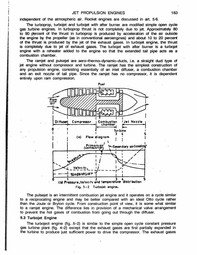
The ramjet and pulsejet are aero-thermo-dynamic-ducts, i.e . a straight duct type of jet engine without compressor and turbine. The ramjet has the simplest construction of any propulsion engine, consisting essentially of an inlet diffuser, a combustion chamber and an exit nozzle of tail pipe. Since the ramjet has no compressor, it is dependent entirely upon ram compression.
^ * / j" Tem^rflTurf~7 ~;
0 1 2 3 V. . . 5(bt Pressure,Velocity ond temperature distributionFig. 5 -2 Turbojet engine.
The pulsejet is an intermittent combustion jet engine and it operates on a cycle sim ilar to a reciprocating engine and may be better compared with an ideal Otto cycle rather than the Joule or Bryton cycle. From construction point of view, it is some what sim ilar to a ramjet engine. The difference lies in provision of a mechanical valve arrangement to prevent the hot gases of combustion from going out through the diffuser.5.3 Turbojet Engine
The turboject engine (fig ..5-2) is sim ilar to the simple open cycle constant pressure gas turbine plant (fig. 4-2) except that the exhaust gases are first partially expanded in the turbine to produce just sufficient power to drive the compressor. The exhaust gases

I
184 ELEM ENTS OF HEAT ENGINES Vol.
leaving the turbine are then expanded to atmospheric pressure in a propelling (discharge) nozzle. The remaining energy of gases after leaving the turbine is used as a high speed jet from which the thrust is obtained for forward movement of the aircraft.
Thus, the essential components of a turbojet engine are :. . An entrance air diffuser (diverging duct) in front of the compressor, which causes
rise in pressure in the entering air by slowing it down. This is known as ram. The pressure at entrance to the compressor is about 1-25 times the ambient pressure.
. . A rotary compressor, which raises the pressure of air further to required value and delivers to the combustion chamber. The compressor is the radial or axial type and is driven by the turbine.
. . The combustion chamber, in which paraffin (kerosene) is sprayed, as a result of this combustion takes place at constant pressure and the temperature of air is raised.
. . The gas turbine into which products of combustion pass on leaving the combustion chamber. The products of combustion are partially expanded in the turbine to provide necessary power to drive the compressor.
. . The discharge nozzle in which expansion of gases is completed, thus developing the forward thrust.
A Rolls-Royce Derwent jet engine employs a centrifugal compressor and turbine of the impulse-reaction type. The unit has 550 kg m ass. The speed attained is 960 km/hour.
5.3.1 W orking Cycle : Air from surrounding atmosphere is drawn in through the diffuser, in which air is compressed partially by ram effect. Then air enters the rotary compressor and major part of the pressure rise is accomplished here. The air is compressed to a pressure of .about 4 atmospheres. From the compressor the air passes into the annular combustion chamber. The fuel is forced by the oil pump through the fuel nozzle into the combustion chamber. Here the fuel is burnt at constant pressure. This raises the temperature and volume of the mixture of air and products of combustion. The mass of air supplied is about 60 times the mass of the fuel burnt. This excess air produces sufficient m ass for the propulsion- jet, and at the same time prevents gas tem perature from reaching values which are too high for the metal of the rotor blades.
The hot gases from the combustion chamber then pass through the turbine nozzle ring. The hot gases which partially expand in the turbine are then exhausted through the discharge (propelling nozzle) by which the remaining enthalpy is converted into kinetic energy. Thus, a high velocity propulsion jet is produced.
The oil pump ad compressor are mounted on the same shaft as the turbine rotor. The power developed by the turbine is spent in driving the compressor and the oil pump.
Fig. 5 -3 .
EntropyA typical turbojet engine cycle on T - <t> diagram.

JE T PROPULSION ENGINES 185
Some starting devicd such as compressed air motor or electric motor, must be provided in the turbojet plant. Flight speeds upto 800 km per hour are obtained from this type of unit.
The basic thermodynamic cycle for the turbojet engine is the Joule or Brayton cycle as shown in T - <t> diagram of fig. 5-3. While drawing this cycle, following simplifying assumptions are made :
- There are no pressure losses in combustion chamber.- Specific heat of working medium is constant.- Diffuser has ram efficiency of 100 percent i.e ., the entering atmospheric air is
diffused isentropically from velocity V0 to zero (V0 is the vehicle velocity through the air).
- Hot gases leaving the turbine are expanded isentropically in the exit nozzle i.e ., the efficiency of the exit nozzle is 100 percent.
5.3.2 Thrust Power and Propulsive Efficien cy : The jet aircraft draws in air and expels it to the rear at a markedly increased velocity. The action of accelerating the mass of fluid in a given direction creates a reaction in the opposite direction in the formof a propulsive force. The magnitude of this propulsive force is defined as thrust. It isdependent upon the rate of change of momentum of the working medium i.e . air, as it passes through the engine.
The basis for comparison of jet engines is the thrust. The thrust, T of a turbojet engine can be expressed as,
T * m (Vj - Vo) ...(5 .1 )where, m - m ass flow rate of gases, kg/sec.,Vj = exit jet velocity, m/sec., and,Vo = vehicle velocity, m/sec.The above equation is based upon the assumption that the m ass of fuel is neglected.
Since the atmospheric air is assumed to be at rest, the velocity of the air entering relative to the engine, is the velocity of the vehicle, Vo. The thrust can be increased by increasing the mass flow rate of gas or increasing the velocity of the exhaust jet for given Vo.
Thrust power is the time rate of development of the useful work achieved by the engine and it is obtained by the product of the thrust and the flight velocity of the vehicle. Thus, thrust power TP is given by
/./ N-m ...(5 .2 )TP = T V0 = m(Vj - V0) Vo —
The kinetic energy imparted to the fluid or the energy required to change the momentum of the mass flow of air, is the difference between the rate of kinetic energy of entering air and the rate of kinetic energy of the exist gases and is called propulsive power. The propulsive power PP is given by
m(Vj2 - Vo2) • f5 ,3 )p p = !'!AYJ —l°_2 N.m/sec.
Propulsive efficiency is defined 'as the ratio of thrust power (TP) and propulsive power (PP) and is the measure of the effectiveness with which the kinetic energy imparted to the fluid is transformed or converted into useful work. Thus, propulsive efficiency r\p is given by
TP m{Vi - VQ) V0 2

2 (V j- Vp) V0 2V0 2 ...(5 .4 )" * = Vj2 - v02 = v j+ v0 m 1 ^
From the expression of rip it may be seen that the propulsion system approaches maximum efficiency as the velocity of the vehicle approaches the velocity of the exhaust gases. But as this occurs, the thrust and the thrust power approach zero. Thus, the ratio of velocities for maximum propulsive efficiency and for maximum power are not the same. Alternatively, the propulsive efficiency can be expressed as
TP TP . . . (5.5)11 p ~ PP = TP + K .E . lossesThermal efficiency of a propulsion is an indication of the degree of utilization of energy
in fuel (heat supplied) in accelerating the fluid flow and is defined as the increase in the kinetic energy of the fluid (propulsive power) and the heat supplied. Thus,
. Propulsive powerThermal efficiency, ti t » - r r ^ i r1 11 Heat supplied
________ Propulsive power . . . (5.6)Fuel flow rate x C .V . of fuel
The overall efficiency is the ratio of the thrust power and the heat supplied. Thus, overall efficiency is the product of propulsive efficiency and thermal efficiency. The propulsive and overall efficiencies of the turboject engine are comparable to the mechanical efficiency and brake thermal efficiency respectively, of the reciprocating engine.Problem - 1 : A je t propulsion unit, with turbojet engine, having a forward speed of 1,100 km/hr produces 14 kN of thrust and uses 40 kg of air per second. Find: (a) the relative exist je t velocity, (b) the thrust power, (c) the propulsive power, and (d) the propulsive efficiency.
(a) Forward speed, VQ = = 305 55 rc sec-
Using eqn. (5 .1), thrust, T = m(Vj - \/0)
i.e ., 14,000 = 40 (Vj - 305-55)
Vi = 14,0°°- + 305-55 = 350 + 305-55 = 655-55 nrVsec.I 40
Thus relative exist jet velocity, Vj = 655-55 m/sec.(b) Using eqn. (5.2)Thrust power, TP - T x VQ 3
= 14,000 x 305-55 = 42,77,700 N.m/sec. or = 4,277.7 kN.m/sec.
186 ELEM ENTS OF HEAT ENGINES Vol. Ill
(c) Using eqn. (5.3),
Propulsive power, PP =m (V22 - V02)
40[(655-55) - (305-55)'
= 6,727 x 103 N.m/sec = 6,727 KN.m/sec or 6,727 kW
(d) Using eqn. (5.4),
JE T PROPULSION ENGINES 187
Propulsive efficiency, r|P =1 +
1 + 655-55'j 1305-55
= 0-636 i.e ., 63.6%
5.4 Ram Je tA french engineer, Rane Lorin invented and patented the first ram jet in 1913. It was
not until the advent of the high speed wind tunnel, however, that the U .S . Navy sponsored research team developed a workable ram jet at Johns Hopkins University.
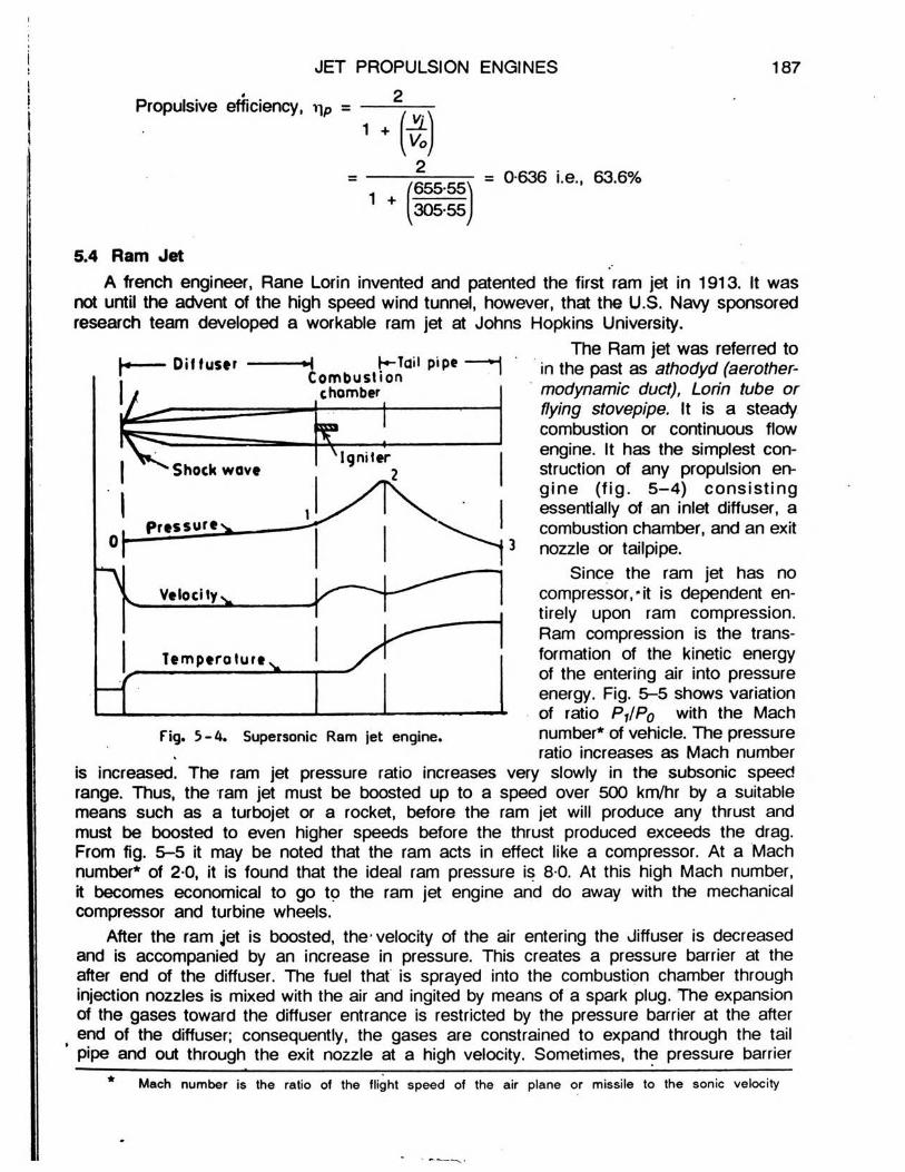
The Ram jet was referred toin the past as athodyd (aerother- modynamic duct), Lorin tube or flying stovepipe. It is a steady combustion or continuous flow engine. It has the simplest construction of any propulsion eng ine (fig . 5 -4 ) co n sistin g essentially of an inlet diffuser, a combustion chamber, and an exit nozzle or tailpipe.
Since the ram jet has no compressor,'■it is dependent entirely upon ram compression. Ram compression is the transformation of the kinetic energy of the entering air into pressure energy. Fig. 5-5 shows variation of ratio P j/P0 with the Mach number* of vehicle. The pressure ratio increases as Mach number
is increased. The ram jet pressure ratio increases very slowly in the subsonic speed range. Thus, the ram jet must be boosted up to a speed over 500 km/hr by a suitable means such as a turbojet or a rocket, before the ram jet will produce any thrust and must be boosted to even higher speeds before the thrust produced exceeds the drag. From fig. 5-5 it may be noted that the ram acts in effect like a compressor. At a Mach number* of 2-0, it is found that the ideal ram pressure is 8-0. At this high Mach number, it becomes economical to go to the ram jet engine and do away with the mechanical compressor and turbine wheels.
After the ram jet is boosted, the- velocity of the air entering the Jiffuser is decreased and is accompanied by an increase in pressure. This creates a pressure barrier at the after end of the diffuser. The fuel that is sprayed into the combustion chamber through injection nozzles is mixed with the air and ingited by means of a spark plug. The expansion of the gases toward the diffuser entrance is restricted by the pressure barrier at the after end of the diffuser; consequently, the gases are constrained to expand through the tail pipe and out through the exit nozzle at a high velocity. Sometimes, the pressure barrier
* Mach number is the ratio of the flight speed of the air plane or missile to the sonic velocity

188 ELEM ENTS OF HEAT ENGINES Vol. Ill
is not effective and that there are pulsations created in the combustion chamber whichaffect the air flow in front of thediffuser.
Since the ram jet engine has no turbine, the temperature of the gases of combustion is not limited to a relatively low figure as in the turbojet engine. Air fuel ratios of around 15*1 are used.This produces exhaust temperatures in the range of 2000°C to 2200°C. Extensive research is being conducted on the development of hydrocarbon fuels that will give 30 percent more energy per unit volume than current aviation gasolines. Investigations are carried Out to determine the possibility of using, solid fuels in the ram jet and in the after burner of the turbojet engine. If powdered aluminium could be utilized as an aircraft fuel, it would deliver over 2-5 times as much heat per
. unit volume as aviation gasoline, while some other could deliver almost four times as much heat.
The temperature, pressure and velocity of the air during its passage through a ram jet engine at supersonic flight are shown in fig. 5M .
The cycle for an ideal ram jet, which has an isentropic entrance diffuser and exit nozzle, is the Joule cycle as shown by the dotted lines in fig. 5-6 . The difference between the actual and ideal jet is due principally to losses actually encountered in the flow system . The sources of these losses are :
. . . Wall friction and flow separation in the subsonic diffuser and shock in the supersonic diffuser.
. . Obstruction of the air stream by the burners which introduces eddy currents and turbulence in the air stream.
. . Turbulence and eddy currents introduced in the flow during burning.
. . Wall friction in the exit nozzle.By far, the most critical component of the
<ram jet is the diffuser. Due to the peculiarities of steamline flow, a diffuser which is extremely
Fig. 5-6 . T - <t> diagram of Ram jet engine.
Moch number — •-
Fig. 5 -5 . Ram pressure ratio versus Mach number of vehicle for sea level condition.

JE T PROPULSION ENGINES 189
Because of the simplicity of the engine, the ram jet develops greater thrust per unit engine weight than any other propulsion engine at supersonic speed with the exception of the rocket engine. The thrust per unit frontal area increases both with the efficiency and the air flow through the engine; therefore much greater thrust per unit area is obtainable at high supersonic speeds. General performance of a ram jet engine in the subsonic range would have a specific fuel consumption between 0.6 to 0*8 kg fuel per N thrust - hr and a specific weight between 0*01 to 0*02 kg per N thrust. The supersonic ram jet engine has a specific fuel consumption between 0*25 to 0-04 and a specific weight between 0-01 to 0-04. Thus, the best performance of the ram jet engine is obtained at flights speeds of 1500 to 3500 km/hr.5.5 Pulse Jet Engine
The pulse jet engine is somewhat sim ilar to a ram jet engine. The difference is that a mechanical valve arrangement is used to prevent the hot gases of combustion from flowing out through the diffuser in the pulse jet engine.
Paul Schmidt patented principles of the pulse jet engine in 1930. It was developed by Germany during W orld-W ar-ll, and was used as the power plant for “buzz bomb".
The turbojet and ram jet engines are continuous in operation and are based on the constant pressure heat addition (Bryton) cycle. The pulse jet is an intermittent combusion engine and it operates on a cycle sim ilar to a reciprocating engine and may be better compared with an ideal Otto cycle rather than the Joule or Bryton cycle.
The compression of incoming air is accomplished in a diffuser. The air passes through the spring valves and is mixed with fuel from a fuel spray located behind the valves. A spark plug is used to initiate combustion but once the engine is operating normally, the spark is turned off and residual flame in the combustion chamber is used for ignition, lin e engine walls also may get hot enough to initiate combustion.
The mechanical valves which were forced open by the entering air, are forced shut when the combustion process raises the pressure within the engine above the pressure in the diffuser. As the combustion products cannot expand forward, they move to the rear at high velocity. The combustion products cannot expand forward, they move to the rear at high velocity. When the combustion produ-pf~ leave, the pressure in the combustion chamber drops and the high pressure air in the c.flbser Tbrces the valves open and fresh air enters the engine.
Since the products of combustion leave at a high velocity there is certain scavenging of the engine caused by the decrease in pressure occasioned by the exit gases. There is a stable cycle set up in which alternate waves of high and low pressure travel down the engine. The alternating cycles of combustion, exhaust, induction, combustion, etc. are related to the acoustical velocity at the temperature prevailing in the engine. Since the temperature varies continually, the actual process is*complicated, but a workable assumption is that the tube is acting sim ilar to a quarter wave length organ pipe. The series of pressure and rarefaction waves move down it at the speed of sound for an assumed average temperatures.
The frequency of the combustion cycle may be calculated from the following expression:
= 4 l cvc*es/sec-
where, a = VfTTT = sound velocity in the medium at temperature, T, andL = length of engine ( from valves to exit).
efficient at a given speed may be quite inadequate at another velocity.

190 ELEM ENTS OF HEAT ENGINES Vol. Ill
A serious limitation placed upon pulse jet engine is the mechanical valve arrangement. Unfortunately, the valves used have resonant frequencies of their own, and under certain conditions, the valve will be forced into resonant vibration and will be operating when they should be shutting. This limitation of valves also limits the engine because the gas goes out of the diffuser when it should go out of the tail pipe.
Despite the apparent noise and the valve limitation, pulse jet engines have several advantages when compared to other thermal jet engines.
. . The pluse jet is very inexpensive when compared to a turbojet.
. . The pulse jet produces static thrust and produces thrust in excess of drag at much lower speed than a ram jet.
. . The potential of the pulse jet is quite considerable and its development and research may well bring about a wide range of application.
5.6 Rocket MotorsThe jet propulsion action of the rocket has been recognised for long. Since the early
beginning, the use of rockets has been in war time as a weapon and in peace time as a signaling or pyrotechnic displays. Although, the rocket was employed only to an insignificant extent in World W ar-I, marked advances were made by the research that was undertaken at that time. In . World W ar-I I, the rocket became a major offensive weapon employed by all warring powers. Rockets and rocket powered weapons have advanced to a point where they are used effectively in military operations.
Rocket type engine differs from the atmospheric jet engine in that the entire mass of the jet is generated from the propellant carried within the engine i.e . the rocket motor carries both the fuel and the oxidizing agent. As a result, this type of engine is independent of the atmospheric air that other thermal jet engines must rely upon. From this point of view rocket motors are most attractive. There are, however, other operational features that make rocket less useful. Here, the fundamentals of rocket motor theory and its applications are discussed.
Rocket engines are classified as to the type of propellant used in them. Accordingly, there are two major groups:
One type belonging to the group that utilizes liquid type propellants and other group that uses solid type propellants.
The basic theory governing the operation of rocket motor is applied, equally to both the liquid and the solid propellant rocket.
Rocket propulsion, at this time, would not be regarded as a competitor of existing means for propelling airplanes, but as a source of power for reaching objectives unattainable by other methods. The rocket motors are under active development programmes for an increasing number of applications. Some of these applications are :
- Artillery barrage rockets,- AntMank rockets,- All types of guided m issiles, v- Aircraft launched rockets,- Jets assisted take-off for airplanes,- Engines for long range, high speed guided m issiles and pilotless aircrafts, and- M ain'and auxiliary propulsion engines on transonic airplanes.It will be repeated again that the rocket engine differs from the other jet propulsion
engines in that the entire mass of the gases in the jet is generated from the propellants

JE T PROPULSION ENGINES 191
.carried within the engine. Therefore, it is not dependent on the atmospheric air to furnish the oxygen for combustion. However, since the rocket carries its own oxidiser, the propellant consumption is very high.
The particular advantages of the rocket are :. . Its thrust is practically independent of its environments.. . It requires no atmospheric oxygen for its operation.. . It can function even in a vacuum.. . It appear to be the simplest means for converting the themochemical .energy of
a propellant combination (fuel plus oxidizer) into kinetic energy associated with a jet flow gases.
Despite its apparent simplicity, the development of a reliable rocket system must be light in weight and the rocket motor must be capable of sustained operation in contact with gases at temperature above 2800° C and at appreciable pressures.The -problem of materials in consequently a major one. Furthermore, owing to the enormous energyreleases involved, problem of ignition, smooth start up, thrust control, cooling etc. arise.
A major problem of development of rocket is selection of suitable propellant to give maximum energy per premium total weight (propellant plus containing vessels) and convenience factors such as a safety in handling, dependability, corrosive tendencies, cost; availability and storage problems. In general, it can be stated that there is a wide variety of fuels that are satisfactory for rocket purpose, but choice of oxidizers is at present distinctly limited.
5.6.1 B asic Theory : Figure 5-7 shows a schematic diagram of a liquid bi-propellantrocket engine. It consists of an injection system , a combustion chamber, and an exitnozzle. The oxidizer and fuel burnt, in the combustion chamber produces a high pressure. The pressure produced is governed by
- Mass rate of flow of the propellants,- Chemicals characteristics of the propellants, and- Cross-section area of the nozzle throat.The gases are ejected to the atmosphere at supersonic speeds through the nozzle.
The enthalpy of high pressure gases is converted into kinetic energy. The reaction to the ejection of the high velocity, produces the thrust on the rocket engine.
The thrust developed is a resultant of the pressure forces acting upon the inner and the outer surface of the rocket engine. The resultant internal force acting on the engine is given by
Resultant force = mp Vj + Pj A N
Combustion chamber Nozzle
Fig. 5 -7 . Schematic diagram of a liquid bi-propellant uncooled rocket motor.

where, mp = Mass rate of propellant consumption, kg/sec,Vj = Jet velocity relative to nozzle, m/sec,V„t = Average value of the x-component of the velocity of gases crossing, Aj,Pj = Exist static pressure, N/m2, and
Aj = Exit area of nozzle, m2.The resultant external forces acting on the rocket engine are PoA» where pQ is the
atmospheric pressure in N/m2. The thrust which is a resultant of the total pressure forces becomes
T - mP Vxj + Aj(P j - P J N . > . (5.8)Let Vj = the exit velocity of the rocket gases, assumed constant and let VXj = X Vj. Then, eqn. (5.8) becomes
7 - \m p Vj + A j{p j - p J N . . . ( 5 . 9 )
The coefficient A. is the correction factor for the divergence angle a of the exitconical section of the nozzle. \ is given by
1 cos 2 ct 1 / \ / p\ = — = — (1 + cos a ) . . . (5.10)4 (1. - cos a ) 2 '
Equation (5.8) shows that thrust of a rocket engine increases as the atmospheric pressure decreases. Therefore, maximum thrust will be obtained when PQ= 0, i.e ., rocket engine produces maximum thrust when operating in a vacuum.
In testing a rocket engine, thrust and propellant consumption for a given time are readily measured. It is convenient then, to express the thrust in terms of the mass rate of flow of propellant and an effective jet velocity, Vej
i.e ., Thrust, T = mp x Vej , . . . (5.11)
The effective je t exit velocity is a hypothetical velocity and for convenience in test work it is defined from eqns. (5.9) and (5.11) as under :
Vej “ k vj + 7^ (P j ~ Po> r ts e 0 - ’ * • (5,12)
The effective jet exit velocity has become an important parameter in rocket motor performance.
The thrust power, TP developed by a rocket motor is defined as the thrust multiplied by the flight velocity, VQ.
TP - TV Q = mp - V9j- VQ N.m/sec. • • . (5.13)
The propulsive efficiency, r\p is the ratio of the thrust power to propulsive power supplied. The propulsive power is the thrust power plus the kinetic energy lost in the exhaust,
i.e ., K .E . Loss = ^ mp (Vej - v f N.m/sec.
Therefore, the propulsive efficiency may be expressed as
__________TP mp Vej Vo_ip - T P * K .E . Loss ' mp V^Vc mp (V j - v f
192 ELEM EN TS OF HEAT ENGINES Vol. Ill

I
J E T p r o p u l s i o n e n g i n e s
n p2(Vo/Vej)
1 + ( Vq/ Vej f
193
. . . (5.14)
Specific Impulse, lsp has become an important parameter in rocket motor performance and is defined as the thrust produced per unit mass rate of propellant consumption.
mn • V,ej = V,ej, m , 3 • • • <5 1 5 >
Specific impulse, with the units, Newtons of thrust produced per kg of propellant burned per second, gives a direct comparison as to the effectiveness among propellants. It is desirable to use propellants with the greatest possible specific impulse, since, this allows a greater useful load to be carried for a given overall rocket weight.
5.6.2. Types of Rocket Motors : The propellant employed in a rocket motor may be a solid, two liquids (fuel plus oxidizer), or materials containing an adequate supply of available oxygen in their chemical composition (monopropellant). Solid propellants are used for rockets which are to operate for relatively short periods, upto possibly 45 seconds. Their main application is to projectiles, guided m issiles, and the assisted take-off aircraft.
Combustion chamber Burns on end
surface only
Nozzle
(a) Restricted burning
Propellant charge Ends prevented from burning by washers
Nozzle
Burns on outside and( b) Unrestricted burning inside cylindrical
” surfaces
Fig. 5 -8 Schematic diagram of a solid propellant rocket. ..
Solid propellant rockets (fig. 5-8) have been of two basic types :. . Unrestricted burning types for projectiles and launching rockets; and. . Restricted burning types for assisted take-off of aircraft and for propelling m issiles.In the unrestricted burning rocket [fig. 5-8(a)] all surfaces of the propellant grain
except the ends are ignited; in restricted burning rockets [fig. 5-8(b)] only one surfaceof the propellant is permitted to burn. Liquid propellant rockets utilizes liquid propellantswhich are stored in the containers outside the combustion chamber. The basic theory of operation of this type of rocket is same as that for solid propellant rocket. Liquid propellant rockets were developed in order to overcome some of the undesirable features of the
HE3 - 13
li

194 ELEM ENTS OF HEAT ENGINES Vol. Ill
solid propellant rockets such as short duration of thrust, and no provisions for adequate cooling or control of the burning after combustion starts. Here, the propellant in the liquid
Fig. 5 -9 . Schematic diagrams of bi-propellant rocket system.
state is injected into a combustion chamber, burned and exhausted at a high velocity through the nozzle. The liquid propellant is also used to cool the rocket motor by circulation of fuels around the walls of the combustion chamber and around the nozzle. Certain liquid fuel, however, such as hydrogen peroxide, burn at such temperatures that no cooling is necessary. Figure 5-9 shows schematic diagrams of pressure feed and pump feed liquid bipropellant rocket system s.Problem -2 : The effective exit je t velocity of a rocket is 3000 m/sec, the forward flight velocity is 1500 m/sec and the propellant consumption is 70 kg per sec. Calculate : (a) Thrust, (b) Thrust power, (c) Specific impulse, (d) Specific propellant consumption, and(e) Propulsive efficiency of the rocket.
(a) Using eqn. (5.11),Thrust, T = mp x Vej = 70 x 3,000 = 2,10,000 N or 210 kN
(b) Using eqn. (5.13),Thrust power, TP = T VQ = 2,10,000 x 1,500 = 315 x 10® N.m/s

(c) Using eqn. (5.14),
Specific impluse, lsp = ~ = 'V Vei «= vej = 3,000 N.s/kg
JE T PROPULSION ENGINES
•p mp
(d) Specific propellant consumption -T mp Vej Vej 3,000
= 3-3 x 10⁻⁴ kg/N.s(e) Using eqn. (5.14),
Propulsive efficiency, r\p = — 2 (K /V e/)__1 ♦ (V o /vy2
2(1500/3000)
mp mp 1
1 + (1500/3000)= 0-8 i.e ., 80%
900 1 00 1500 1600 2100Velocity, km/hr —
Fig. 5-10. Propellant or fuel consumption versus flight speed for different propulsion systems.
5.7 Com parison of the Various Propulsion System sFigure 5-10 shows the specific propellant consumption in kg per kN thrust
speed for different engines. The curves in this figure indicate that the use of
195
versusrocket

196 ELEM EN TS OF HEAT ENGINES Vol. Ill
engines to power air planes, as we know them today, is not feasible because of their high fuel consumption. Also, the use of ram jet engines is not economical at lower than 1500 km/hr vehicle speeds.
CftEj 60 I— V w nmneiier Figure 5-11 shows variation of thrust
with altitude for different propulsion sys- 5 \ terns. It may be noted that the thrust« 60 "v a ’ of rocket motor increases with altitude8 N, ' while the thrust of other types of vehicles
^ t k ®/1 decreases with altitude.
cOJow0)0.
Rocket
Unsupercharged reciprocating
— engine with - propeller Relative
air densit
Supercharged reciprocating engine with \ l propeller
6 12 Altitude km>
Fig. 5-11 Variation of thrust with altitude for different propulsion systems.
Figure 5-12 gives relative picture of the probable operating envelope of the various propulsion system s.
0 ? 10 3 4Flight velocity, km/sec *
Fig. 5-12 Comparison of probable best performance for various propulsion engines.

JE T PROPULSION ENGINES 197
T uto ria l- 5Fill in the gaps to complete the following statements :
(a) The two main categories of jet propulsion system s are th e jet erlgines and%
(b) T h e an d are aero-thermodynamic-ducts i.e., a straight duct type of jetengines without compressor and turbine.
(c) In world war I I , became a major offensive weapon employed by all warringpowers.
(d) Rocket motor cannot compete, as far as efficiency is concerned, with other formsof propulsive system s, in the ’ speed range.
(e) Relative fuel consumption per. unit power output i s for reciprocating engineand i s for rocket motor, r
[ (a) atmospheric, rockets, (b) ramjet, pulse jet, (c) rocket, (d) subsonic, *(e) lowest, highest.] Choose correct phrase/s to complete the following statements:
(i) The fuel used in turbojet engine is :(a) liquid hydrogen, (b) high speed Diesel oil, (c) kerosene, (d) methylalcohol.
(ii) In a jet propulsion power unit, the inlet duct of diverging shape is used to :(a) collect more air, (b) convert kinetic energy of air into pressure, (c) providerobust structure, (d) none of the above.
(iii) The air entry velocity in a rocket as compared to aircraft is :(a) sam e, (b) more, (c) less, (d) zero, (e) depends on power and speed.
(iv) The propulsive power of the rocket is given by :,_ v V i2 - V22 (V i - V2) 2 \/i2 V12 - V22(a) ----- 2----- ’ ^ ------ 2------ ’ ^ ~ T ' ^ 4--
where V1 = jet velocity, and V2 = rocket velocity.(v) The air-fuel ratio in a jet engine will be of the order of :
(a) 20 : 1, (b) 10 : 1, (c) 60 : 1, (d) 100 : 1.(vi) The maximum temperature in a gas turbine may be of the order of :
(a) 500°C, (b) 1,000°C, (c) 2,000°C, (d) 2,500°C.(vii)For speeds above 3,000 km/hour, it is advantageous to use :
(a) turbojet engine, (b) ramjet engine, (c) rocket, (d) propellers.(viii)The ramjet engine :
(a) is not self operating at zero flight speed.(b) is self operating at zero flight speed.(c) produces a jet consisting of plasma.(d) none of the above.
[(i) c, (ii) c, (iii) d, (iv) a, (v) c, (vi) b, (vii) b, (viii) a](a) What is meant by jet propulsion engines ?(b) Classify jet propulsion engines and distinguish between atmospheric jet engines
and rockets.(a) State the two laws on which propulsion of a vehicle through a fluid medium is
based.(b) List the types of atmospheric jet engines. How they differ from each other ?(c) Name the two types of rocket motors.

198 ELEM ENTS OF HEAT ENGINES Vol. Ill
5. (a) Describe with the help of a neat sketch the working of a turbojet engine.(b) Sketch the variations in pressure, temperature and velocity of the working medium
while it passes through the turbojet engine.6. (a) State the applications of atmospheric jet engines and rocket engine.
(b) Define thrust, thrust power, propulsive power and propulsive efficiency of a turbojetengine.
7. (a) Define propulsive efficiency and derive its expression. State the condition for 100percent propulsive efficiency and comment on this situation.
(b) What is the role of a diffuser in a turbojet engine ? Name jet engine in which the compression is fully dependent on ram effect.
8. (a) Define overall efficiency of turbojet engine and state how it is related to its thermaland propulsive efficiencies ?
(b) A jet propulsion unit with turbojet engine flies at a speed of 1,000 km/hr. It has an exit jet velocity of 600 m/sec and it consumes 32 kg of air per second. Find:(i) the thrust, (ii) the thrust power, (iii) the propulsive power, and (iv) the propulsiveefficiency.
[(i) 10,310 N; (ii) 2,864-23 KN/Sec; (iii*) 4,525.23 kW (iv) 63.23%]9. (a) Draw a schematic diagram of a ramjet engine and lable all components.
(b) Describe the operation of a ramjet engine.10. (a) Why must a ramjet engine be boosted to speeds around 650 km per hour ?
(b) What are the advantages and disadvantages of ram jet engines ?11. (a) Draw schematic diagram of a pulsejet engine.
(b) Describe the operation of a pulsejet engine.(c) What are the advantages and disadvantages of pulsejet engine ?
12. (a) What are rocket motors ?(b) What are the advantages and disadvantages of rocket motors ?
13. The effective jet velocity of a rocket is 2,700 m per sec, the forward flight velocityis 1350 m per sec and the propellant consumption is 73-3 kg per second. Estimate:(a) Thrust, (b) Thrust power, and (c) Propulsive efficiency.
[(a) 197-91 kN, (b) 267-18 x 103 kN/Sec. (c) 80%]14. Given the following data for a bipropellant rocket motor :
Flight velocity = 650 rrVsec Effective jet velocity = 1950 m/sec.Rate of propellant consumption = 7 kg/sec.
Calculate : (a) thrust, and (b) propulsive efficiency.[(a) 13,650 N, (b) 60%]
15. Compare the various types of jet propulsion systems as to their specific fuelconsumption, best speed range and relative weight.