heat pump performance verification...
TRANSCRIPT

- 1 -
Heat Pump Performance Verification
PROGRAM
Nebraska Public Power District and our Wholesale Partners are excited to bring you a new heat pump performance verification program. This booklet will walk you through the steps necessary to conduct a system performance verification as well as complete the application form. Key process steps include:
1) Determine System CFM (pages 2-4) 2) Heat Pump Capacity – Heating Mode (pages 5-6) OR
Heat Pump Capacity – Cooling Mode (pages 7-9) 3) Complete The Form (last two pages) NOTE: Example Scenario Data – Page 10
Recommended tools:
• Air pressure measurement devise (i.e. magnehelic, digital manometer, incline manometer, etc.)
• Temperature probe • Equipment specifications
Additional forms and information is located at www.nppd.com (go to “My Home”, and then under the “Residential “ heading, click on “HP Performance Verification Program”). If you have additional questions please contact: Roger Hunt at 402-239-9406; John Koperski at 308-289-0463; Chad Podolak at 402-563-5482 or Kelly Beiermann at 402-563-5415.

- 2 -
Static Pressure Readings
•
•
Option #1
CFM CALCULATION Using Total External Static Pressure
(* Enter Results On Application Form - Section #4A) Return Air Static (after filter) _______
Supply Air Static (at plenum) _______
Coil Static (from manufacturer) _______ (need to include evaporator coil’s static pressure if the coil is located between the fan and the supply air static reading - see page 3 for an example chart) Total External Static Pressure* (Form - #4A) _______
CFM* (Form - #4A) _______ (per Mfg. Specifications from the total external static pressure – see chart on bottom of page 3) NOTE: Total External Static Pressure can determine CFM for any furnace. It is the summation of everything external to the furnace cabinet (i.e. return duct, supply duct, and likely the indoor coil). For electric furnaces, there is another option to the total external static pressure and that is discussed on page 4 and is listed as option #2.

- 3 -
COIL STATIC PRESSURE DROP (IN. W.C.)
AIR DELIVERY – CFM (with filter)
• If the return static pressure reading is taking before (upstream) of the filter, a static pressure
value has to be included for the static pressure of the filter. • Other equipment specification that may apply.
• May have to include a “correction factor” if return air temperature is less than 75°F or more than 85°F.
• Other equipment specification that may apply.
0.1 0.2 0.3 0.4 0.5 0.6 0.7 0.8 0.9 1.0
High 1440 1400 1355 1300 1240 1170 1090 1000 890 745Mid-High 1180 1165 1150 1125 1085 1030 970 890 785 645Medium 1015 1020 1010 990 965 925 875 800 700 560Med-Low 885 885 880 865 845 815 770 700 605 475
Low 695 700 700 690 670 640 600 540 460 345
36070
EXTERNAL STAIC PRESSURE (In. wc)SPEEDSIZE
UNIT SIZE BULB900 1000 1100 1200 1300
0.16 0.20 0.24 0.28 0.33DRY 0.14 0.17 0.21 0.24 0.28WETA036
AIR QUANTITY (CFM)
- 4 -
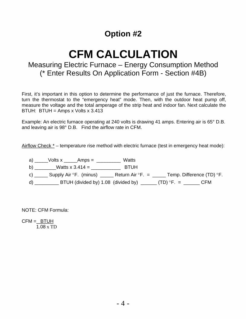
Option #2
CFM CALCULATION Measuring Electric Furnace – Energy Consumption Method
(* Enter Results On Application Form - Section #4B)
First, it’s important in this option to determine the performance of just the furnace. Therefore, turn the thermostat to the “emergency heat” mode. Then, with the outdoor heat pump off, measure the voltage and the total amperage of the strip heat and indoor fan. Next calculate the BTUH: BTUH = Amps x Volts x 3.413
Example: An electric furnace operating at 240 volts is drawing 41 amps. Entering air is 65° D.B. and leaving air is 98° D.B. Find the airflow rate in CFM. Airflow Check * – temperature rise method with electric furnace (test in emergency heat mode): a) _____Volts x _____Amps = _________ Watts b) ________Watts x 3.414 = ___________ BTUH c) _____ Supply Air °F. (minus) _____ Return Air °F. = _____ Temp. Difference (TD) °F. d) _________ BTUH (divided by) 1.08 (divided by) ______ (TD) °F. = ______ CFM NOTE: CFM Formula: CFM = BTUH 1.08 x TD

- 5 -
HEATING MODE Heat Pump Capacity Verification
(* Enter Results On Application Form - Section #5A & 6)
1) Measured Capacity* (Form - #5A)
BTUH = CFM x TD x 1.08
__________ = __________ x __________ x 1.08
NOTE: Make sure the TD is obtained when the heat pump is running WITHOUT any strip heat or backup heat on!
2) Manufacturer’s Rated Capacity* (Form - #6)
__________ Current Outdoor Air Temperature (OAT) – at Outdoor Coil
__________ BTUH – Manufacturer’s Rated Capacity for
Above OAT (see page 6)
3) % Difference* (Form - #6)
Rated (-) Measured (÷) Rated (=) % Capacity Capacity Capacity Difference
________ (-)________ (÷)________ = ________ % Difference
% Difference must be within 10% to be in compliance.
- 6 -
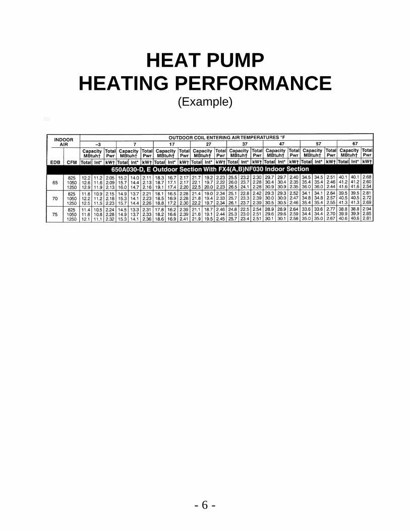
HEAT PUMP HEATING PERFORMANCE
(Example)

- 7 -
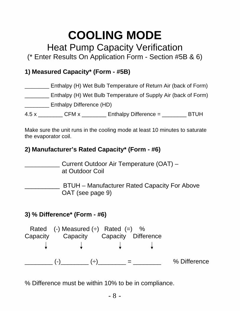
COOLING MODE Heat Pump Capacity Verification
TOTAL HEAT (ENTHALPY) IS
THE SUM OF SENSIBLE HEAT AND LATENT HEAT
The total heat content of air is call enthalpy. It is measured in BTU per pound of standard dry air, and is abbreviated as “H” in formulas and equations. Sensible heat is the heat, which causes a change in temperature of substance. Latent heat is the heat, which causes a change of state without any changes of temperature.
TOTAL HEAT EQUATION IS:
BTUH = CFM X HD X 4.5
Total heat change, as determined from wet bulb temperatures is the only means of checking total cooling capacity in the field. Dry bulb temperature drop, over a coil, tells only the sensible cooling performance.
- 8 -
COOLING MODE Heat Pump Capacity Verification
(* Enter Results On Application Form - Section #5B & 6)
1) Measured Capacity* (Form - #5B)
________ Enthalpy (H) Wet Bulb Temperature of Return Air (back of Form)
________ Enthalpy (H) Wet Bulb Temperature of Supply Air (back of Form)
________ Enthalpy Difference (HD)
4.5 x ________ CFM x ________ Enthalpy Difference = ________ BTUH Make sure the unit runs in the cooling mode at least 10 minutes to saturate the evaporator coil. 2) Manufacturer’s Rated Capacity* (Form - #6)
__________ Current Outdoor Air Temperature (OAT) – at Outdoor Coil
__________ BTUH – Manufacturer Rated Capacity For Above
OAT (see page 9)
3) % Difference* (Form - #6)
Rated (-) Measured (÷) Rated (=) % Capacity Capacity Capacity Difference
________ (-)________ (÷)________ = ________ % Difference % Difference must be within 10% to be in compliance.

- 9 -
COOLING CAPACITY (Example)
- 10 -
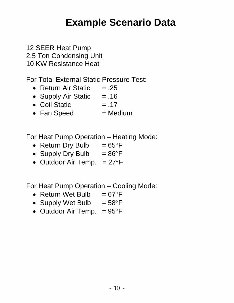
Example Scenario Data 12 SEER Heat Pump 2.5 Ton Condensing Unit 10 KW Resistance Heat For Total External Static Pressure Test: • Return Air Static = .25 • Supply Air Static = .16 • Coil Static = .17 • Fan Speed = Medium
For Heat Pump Operation – Heating Mode:
• Return Dry Bulb = 65°F • Supply Dry Bulb = 86°F • Outdoor Air Temp. = 27°F
For Heat Pump Operation – Cooling Mode:
• Return Wet Bulb = 67°F • Supply Wet Bulb = 58°F • Outdoor Air Temp. = 95°F

- 11 -
Heat Pump Performance Verification - Program Guidelines
• The heat pump performance verification program is applicable for installations after January 1, 2005.
• Qualifying systems include any SEER heat pump installed in a residential application that is either a newly constructed house, or a conversion situation in which the existing central air conditioner is replaced with a new heat pump.
• Like heat pump system upgrades are not eligible (ex. existing air source heat pump replaced with a new air source heat pump).
• Dealers will be paid $150 for systems in compliance. • If there are two heat pump systems conditioning the house, dealers will be paid $75 for
the second heat pump system that also is in compliance. • To participate, the heat pump installer will conduct a performance test on the system to
ensure it is operating as intended. Typical performance information required includes: airflow in c.f.m., measured Btuh output, design Btuh output and outdoor air temperature. If the measured output is within 10% of design output (established by the manufacturer), then the system is assumed to be within compliance.
• The dealer completes an application form and sends it to the homeowner’s electric utility. Typical information on the form includes; the performance data of the heat pump system, homeowner and dealer name, address, etc.
• This program is completely voluntary for dealers. • The installer has a one-year period from when the equipment is installed to when the
application form would still be accepted. • HVAC dealers will receive one check a month for successful applications that are
processed, regardless of the number of different participating electric utilities that are involved. Accompanying this check will be a report indicating the applications that have been processed, and information such as; homeowner’s name, homeowner’s electric utility, date, etc.
• Utilities may inform their customers’ (the homeowner) that their system has passed the heat pump performance verification test, per the data submitted by their HVAC dealer.
• NPPD reserves the right to conduct random heat pump performance verification tests with the dealer to ensure accuracy.
• If it is determined that the information provided by the dealers is fraudulent, disciplinary actions will be taken.

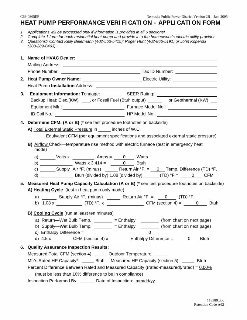
C69-0305EF Nebraska Public Power District Version 2B—Jan. 2005
HEAT PUMP PERFORMANCE VERIFICATION - APPLICATION FORM 1. Applications will be processed only if information is provided in all 6 sections! 2. Complete 1 form for each residential heat pump and provide it to the homeowner’s electric utility provider. 3. Questions? Contact Kelly Beiermann (402-563-5415); Roger Hunt (402-866-5191) or John Koperski
(308-289-0463).
1. Name of HVAC Dealer: Mailing Address: Phone Number: Tax ID Number:
2. Heat Pump Owner Name: Electric Utility: Heat Pump Installation Address:
3. Equipment Information: Tonnage: SEER Rating: Backup Heat: Elec.(KW) , or Fossil Fuel (Btuh output) or Geothermal (KW) Equipment Mfr.: Furnace Model No.: ID Coil No.: HP Model No.:
4. Determine CFM: (A or B) (* see test procedure footnotes on backside) A) Total External Static Pressure in inches of W.C. Equivalent CFM (per equipment specifications and associated external static pressure)
B) Airflow Check—temperature rise method with electric furnace (test in emergency heat mode)
a) Volts x Amps = 0 Watts b) Watts x 3.414 = 0 Btuh c) Supply Air °F. (minus) Return Air °F. = 0 Temp. Difference (TD) °F. d) Btuh (divided by) 1.08 (divided by) (TD) °F = 0 CFM
5. Measured Heat Pump Capacity Calculation (A or B) (* see test procedure footnotes on backside) A) Heating Cycle (test in heat pump only mode)
a) Supply Air °F. (minus) Return Air °F. = 0 (TD) °F. b) 1.08 x (TD) °F. x CFM (section 4) = 0 Btuh
B) Cooling Cycle (run at least ten minutes) a) Return—Wet Bulb Temp. = Enthalpy (from chart on next page)b) Supply—Wet Bulb Temp. = Enthalpy (from chart on next page)c) Enthalpy Difference = 0 d) 4.5 x CFM (section 4) x Enthalpy Difference = 0 Btuh
6. Quality Assurance Inspection Results: Measured Total CFM (section 4): Outdoor Temperature: Mfr’s Rated HP Capacity*: Btuh Measured HP Capacity (section 5): Btuh Percent Difference Between Rated and Measured Capacity ((rated-measured)/rated) = 0.00%
(must be less than 10% difference to be in compliance) Inspection Performed By: Date of Inspection: mm/dd/yy
118389.doc Retention Code A62

Static Pressure Readings
•
•
Enthalpy Chart Wet Bulb Temp. Enthalpy Wet Bulb Temp. Enthalpy 40 15.23 60 26.46 41 15.70 61 27.15 42 16.17 62 27.85 43 16.66 63 28.57 44 17.15 64 29.31 45 17.65 65 30.06 46 18.16 66 30.83 47 18.68 67 31.62 48 19.21 68 32.42 49 19.75 69 33.25 50 20.30 70 34.09 51 20.86 71 34.95 52 21.44 72 35.83 53 22.02 73 36.74 54 22.62 74 37.66 55 23.22 75 38.61 56 23.84 76 39.57 57 24.48 77 40.57 58 25.12 78 41.58 59 25.78 79 42.62 Footnotes for the following front-side sections: Miscellaneous
• An average of multiple temperature readings taken over a cross-section of the duct will provide the most accurate temperature.
• When determining CFM with ECM motors, identify the CFM that the motor is programmed for. Section 4A) Static pressure
• One method of determining the external static pressure is to take 1) one reading before the fan, and 2) the other reading should be taken either before or after the indoor coil/strip heat. If the pressure is taken after the indoor coil/strip heat, static pressure values will have to be added to the total to compensate for these components. The values for these two components should be in the equipment specifications.
• Once the total external static pressure is determined, the equipment specifications for that furnace will indicate what the equivalent CFM is.
Section 4B) Airflow check • Operate thermostat in emergency heat mode. • Heat pump should not be operating to determine CFM. • Make sure fan speed is at 100% (or the speed at which the fan
operates if the heat pump would be on). • Temperature readings—make sure the temperature probe and
the resistance heaters are not in direct sight of each other. Section 5A) When checking the heat pump capacity in the heating
mode, make sure the auxiliary heat is switched off. Section 5B) When checking capacity in the cooling mode, make sure
the system runs at least 10 minutes to get a wet indoor coil. Section 6) Manufacturer’s rating HP capacity—this Btuh value is
obtained from the equipment specifications integrated performance curve (indicates Btuh output for various outdoor air temperatures).
Nebraska Public Power District Version 2B—Jan. 2005