heat pump pool & spa heater · • occasional chemical shock dosing of the pool or spa water...
TRANSCRIPT

Catalog No. 6000.56C Effective: 01-12-18 Replaces: 11-20-17 92-105917-01-04
FOR YOUR SAFETY: Do not store or use gasoline or other flammable vapors and liquids or other combustible materials in the vicinity of this or any other appliance. To do so may result in an explosion or fire.
Heat Pump Pool & Spa Heater
NOTE: The instructions in this manual are for the use of qualified individuals specially trained and experienced in the installation and maintenance of this type of equipment and related system components. Installation and service personnel are required by some states to be licensed. Persons not qualified shall not attempt to install, service, or maintain this equipment.
This manual should be maintained in legible condition and kept adjacent to the heat pump pool heater or in a safe place for future use.
Model Series2450, 3450, 4450,
5450, 6450, 6450PD, 6450HC, 8450 & 8450HC
INSTALLATION AND OPERATION MANUAL

2
Rev. 4 reflects the following:Additions: 2450-4450 Model Information.
ATTENTION: Please Take This Opportunity to Quickly Register Your Unit!!
While your unit is being installed by your professional and licensed installer of choice, Please Take This Opportunity to Quickly Register Your Unit!! With the necessary information in hand, Registering your new Heat Pump Pool Heater only takes a few moments and is the only way to assure any verifiable warranty procedures during the span of your unit’s period of protection.
Using the diagram at the bottom of the page (Fig. i) please locate and record your model and serial number. Once you have done this, please make sure you also have the following information on hand:
NAMEPLATE
• Name, phone number, and email address of homeowner
• physical address of where the unit is installed; please include any ‘subdivision’ or similar information
• any service challenges present at the house/neighborhood: gated community, locked access at house, guard dog, etc.
• date of installation of the new unit
• name and phone number of the professional and licensed entity that performed the installation for you
Fig. i: Model and Serial Number Location
With all of the above information in hand, please contact us and ask to register your brand new heat pump or Online:
http://warranty.raypak.com
You will be given a Warranty Registration Confirmation number which you should notate and keep in one location along with your Installation & Owner’s Manual, a copy of your warranty (provided with your manual) and the above information.
This unit is equipped with a QR Code on the rating plate, as shown in Fig. i, which will take you to the www.raypak.com website where the IO manual and other documents can be easily accessed.
This would also be a good time to review both the manual and the warranty so that you are aware of how to correctly operate your new equipment as well as how to keep from voiding any aspects of your warranty. During the life of your unit, please feel free to use the above phone number, or the one conveniently located right on the unit, to contact us with any questions you may have about operation, warranty, and/or service.
Thank You Very Much Choosing us to Satisfy Your Pool Heating needs!!
Warranty Registration Confirmation #:
QR CODE

3
Water Chemistry(Corrosive water voids all warranties)
For your health and the protection of your pool equipment, it is essential that your water be chemically balanced. The following levels must be used as a guide for balanced water.
• Occasional chemical shock dosing of the pool or spa water should not damage the heater providing the water is balanced. However, it is highly recommended that the heat pump pool heater is isolated via shut off valves before any aggressive chemical treatment.
• Automatic chemical dosing devices and salt chlorinators are usually more efficient in heated water. Unless controlled, they can lead to excessive chlorine level which can damage your heater.
• Further advice should be obtained from your pool or spa builder, accredited pool shop, or chemical supplier for the correct levels for your water.
Recommended Level(s) Fiberglass Pools Fiberglass Spas Other Pool & Spa Types
Water Temp. (°F / °C) 68 °F to 88 °F (20°C to 31°C)
89 °F to 104 °F (32°C to 40°C)
68 °F to 104 °F (20°C to 40°C)
pH 7.3 to 7.4 7.3 to 7.4 7.6 to 7.8
Total Alkalinity (PPM) 120 to 150 120 to 150 80 to 120
Calcium Hardness (PPM) 200 to 300 150 to 200 200 to 400
Salt (PPM) 4500 MAXIMUM 4500 MAXIMUM 4500 MAXIMUM
Free Chlorine (PPM)* 2 to 3 2 to 3 2 to 3
Total Dissolved Solids (PPM) 3000 MAXIMUM** 3000 MAXIMUM** 3000 MAXIMUM**
*Free Chlorine MUST NOT EXCEED 5 PPM!** In salt water chlorinated pools, the total TDS can be as high as 6000ppm.

4
Water Chemistry 3Warnings 5Pay Attention to These Terms 5Introduction 6Installation Considerations 6Electrical Connections 11Water Connections 11Pressure Drop 12HPPH Control Display 12User Modes 13HPPH Control Menus 14USER MENU — Heat ONLY, Power Defrost and Heat/Cool Models 15INSTALLER/SERVICE MENU — HEAT ONLY Configuration 17INSTALLER/SERVICE MENU — POWER DEFROST Configuration 21INSTALLER/SERVICE MENU — HEAT/COOL Configuration 25Control Settings 29Set Current Time 29C/F Display 29Spa Max Temp 29Pool Max Temp 29Pump Periods 29Temperature Control 29Additional Features 29Pump Control 29Low Ambient (Outside) Lockout 29Control Lock Box Mode 29AUX Mode 30Remote Pool Operation 31Pool Heat Mode 31Pool Cool Mode (HEAT/COOL models ONLY) 31Pool Auto Mode (HEAT/COOL models ONLY) 31TIMED SPA Mode 31Fault History 31Run Hours/Cycles 31Compressor Start Delay 32Minimum Run Time 32Defrost Operation 32
3-Way Valve Control 32Battery Back-up 33High Water Temperature Limit 33High Pressure Switch Lockout 33Low Pressure Switch Lockout 33Water Pressure Switch 33Sequence of Operation 33Digital Controls Operating Instructions 34To Increase or Decrease the Desired Water Temperature (Pool or Spa Mode) 34 Select Temperature in °C or °F 34Heat/Cool Operation 34System Start-Up 35Seasonal Start-Up or Annual Check 35Summer Shutdown 35Freeze Protection 35System Drain-Down 35Continuous Pump Operation 36Maintenance 36Air Coil Cleaning 36Cabinet Care (optional) 36Unplug Condensation Drain Holes 36Troubleshooting 36Operational Status Messages 38Error Messages 39Service Call Verification 40Power Supply 40Water Flow 40Time Clock Adjustment 40Set Factory Defaults 40Service Access to Heaters 40Plumbing Diagrams 42Wiring Diagram — 208V/230V Single-Phase — Digital Models 46 Installing a Remote ControlDevice 47Heater 2-Wire Controllers (Heat Only) 473-Wire Controllers 472-Wire Controllers For “Chill” Mode - Heat/Cool Models Only 47Resistance Sensor Values 48
Contents

5
CAUTION: Improper chemical content in a swimming pool or spa can damage the heat pump pool heater. DO NOT add pool/spa chemicals to the pool/spa via the skimmer or any other apparatus (feeder, chlorinator, etc.) that is on the influent side (i.e. before) of the heater. This will damage the heat pump pool heater and could void the heat pump pool heater warranty. ALWAYS follow the product manufacturer’s directions when adding any chemicals to your pool.
DANGER: Indicates the presence of immediate hazards which will cause severe personal injury, death or substantial property damage if ignored.
WARNING: Indicates the presence of hazards or unsafe practices which could cause severe personal injury, death or substantial property damage if ignored.
CAUTION: Indicates the presence of hazards or unsafe practices which could cause minor personal injury or product or property damage if ignored.
NOTE: Indicates special instructions on installation, operation, or maintenance which are important but not related to personal injury hazards.
Warnings — Pay Attention to These Terms
This manual, as well as the pool/spa heat pump pool heater itself, contains ANSI-approved product safety signs and labels. Please read these signs and labels, as they convey important safety information about hazards that may be potentially present in and around the heat pump pool heater.
CAUTION: Elevated water temperature can be hazardous. The U.S. Consumer Product Safety Commission has these guidelines:
1. Spa water temperatures should never exceed 104°F (40°C). A temperature of 100°F (38°C) is considered safe for a healthy adult. Special caution is suggested for young children.
2. Drinking of alcoholic beverages before or during spa or hot tub use can cause drowsiness which could lead to unconsciousness and subsequently result in drowning.
3. Pregnant Women Beware! Soaking in water over 102°F (39°C) can cause fetal damage during the first three months of pregnancy resulting in the birth of a brain-damaged or deformed child. Pregnant women should stick to the 100°F (38°C) maximum rule.
4. Before entering the spa or hot tub, users should check the water temperature with an accurate thermometer; spa or hot tub thermostats may err in regulating water temperatures by as much as 4°F (2.2°C).
5. Persons with a medical history of heart disease, circulatory problems, diabetes, or blood pressure problems should obtain a physician’s advice before using pools or hot tubs.
6. Persons taking medications which induce drowsiness, such as tranquilizers, antihistamines, or anticoagulants, should not use spas or hot tubs.
WARNING: These heat pump pool heaters are charged with R-410A refrigerant. Ensure that all service work is done with gauges and equipment suitable for R-410A.
EFFICIENCY TESTING NOTICE: For purposes of verifying or testing efficiency ratings, the test procedure in Title 10 APPENDIX P to Subpart B of Part 430 (Uniform Test Method for Measuring the Energy Consumption of Pool Heaters) and the clarifying provisions provided in the AHRI Operations Manual 1160 that were applicable at the date of manufacture should be used for test set up and performance. Charging Chart are available at https://www.raypak.com/customer-support/heat-pump-charging-charts. These should only be used by certified HVAC technicians to check or adjust refrigerant charge for proper operation.

6
Introduction
This manual contains important information on the use, maintenance and troubleshooting of your new heat pump pool heater. This unit must be properly installed, maintained and operated for optimal perfor-mance.
This heat pump pool heater is an extremely efficient, economical machine designed specifically for swim-ming pool heating. It is similar in design and operation to a typical residential air conditioning system. The unit employs a hermetic motor/compressor operating in a refrigeration cycle to extract heat from ambient air and deliver it to the circulating pool water.
As with all heat pump pool heaters, compared to other types of heaters such as gas or oil-fired, this heat pump pool heater has lower heating capacity on a BTUH/hr basis. As a result, it will be required to oper-ate longer to accomplish the desired results. It may, at certain times, operate as much as 24 hours per day. However, this should not be of concern to the owner, because the unit is designed to operate continuously. Even though it may operate continuously for many hours, it will still heat the pool with greater economy than other types of fossil fuel heaters.
Place a cover or blanket over the pool at night and other non-use periods. This will keep evaporation, the main cause of main heat loss, to a minimum, and will greatly reduce pool heating costs. During warmer weather, the cover may be required only at night.
Installation Considerations
Situate the heat pump pool heater carefully to minimize installation costs while providing maximum efficiency of operation, and to allow adequate service access, as follows:
• For unrestricted air intake and service access, position each side of the unit at least 1 ft (30 cm) from walls, pipes and other obstructions.
WARNING: This unit is designed for outdoor installation; DO NOT install it in an enclosed area such as a shed or garage.
• This unit features an ‘up-flow’ discharge for quiet operation. Air is pulled up through the evaporator coil and discharged through the top grille. Allow at least 5 ft (1.5 m) clearance above the unit for unrestricted air discharge. DO NOT install the unit under a porch or deck. Refer to Fig. 1. Recircula-tion of cold discharge air back into the evaporator coil will greatly reduce the unit’s heating capacity and efficiency.
• To minimize water piping, locate the unit as close as possible to the existing pool pump and filter.
• Irrigation water should be directed away from the heat pump pool heater - irrigation water spray can damage the heat pump pool heater.
• Rain water run offs - the unit is designed to oper-ate outdoors and can be exposed to rain. Howev-er, rain water run off falling directly onto the unit can cause damage and/or shorten the life of your unit. This may also void your warranty. Install rain gutters or rain diverters on your roof if the unit is installed in a position where contact with rain run off may occur.
WARNING: This pool/spa heat pump pool heater is an electromechanical machine that incorporates a pressurized refrigerant gas in a sealed system. ONLY trained and qualified service personnel are authorized to install or service this equipment. Without proper training and knowledge of such equipment, any attempt to install or service the unit could result in serious injury or even death.
WARNING: Do not install the unit within 3 ft (0.9m) of fossil fuel burning heaters. Air intake along the sides of this heat pump pool heater could disturb the combustion process of the unit, and could cause damage or personal injury.• Mount the unit on a level, sturdy base, preferably a concrete slab. The size of the base should be at least 3 ft by 3 ft (0.9m x 0.9m) - slightly larger if hurricane tie down brackets are installed. See pages 8-10 for more details.
CAUTION: The unit’s supporting base must be high enough to keep it completely free of standing water at all times.
NOTE: Hurricane tie down brackets, tie down screws, 2 x union halves, 2 x 45-degree PVC elbows, the printed warranty and the I&O manual are located in an accessory box mounted on the pallet beside the heater inside the packaging. DO NOT throw away without removing all components.

7
GASHEATER
3 FT(09.m)MIN
AIRFLOW
IN
AIRFLOW
IN
AIR FLOW OUT
60” (1.52m) MIN
12”(0.3m)MIN
Fig. 1: Installation Clearances
• It is important to keep the area next to the heat pump pool heater clear of shrubs, bushes and chemicals containers. They could prevent air from circulating fully through the heat pump pool heater, and will affect the operation of the heat pump pool heater or damage the heat pump pool heater.
• When installed in areas where freezing tempera-tures can be encountered, drain the water circuit to prevent possible freeze-up damage. Refer to Freeze Protection section on page 35 for proper procedures.
• If the location of the HPPH is below the water line of the pool, the Water Pressure Switch (WPS) or Water Flow Switch (WFS) might need to be adjusted or an external WFS might be needed.
• For high wind installation requirements, refer to the figures on page 8, 9 or 10 – depending on model size.
Fig. 2: Base Design - Handling
NOTE: The base is designed with recessed areas to allow the use of hand trucks or lifting without the possibility of pinching fingers as shown in Figure 2.

8
Min
imum
pad
dim
ensi
ons
are
43-1
/4"
x 43
-1/4
" x
4" t
hick
.
Scr
ews
to a
ttac
h br
acke
ts t
o un
it ar
e su
pplie
d w
ith t
he u
nit
- D
O N
OT
use
scre
ws
not
spec
ified
or
prov
ided
by
man
u-fa
ctur
er.
Scr
ews
are
stai
nles
s st
eel #
10 x
3/4
" se
lf dr
illin
g.
Each
bra
cket
req
uire
s 4
scre
ws
atta
ched
to
the
unit.
AN
CH
OR
SC
HE
DU
LE:
CO
NCRET
E:(4
" TH
ICK M
IN,
3000
PSI
MIN
.)
SUBSTRATE
DESCRIPTION
DIM
. 1
DIM
. 2
DIM
. 3
DIM
. 4
4.50
" M
AX O
FFSET
FRO
M D
ATU
M F
ACE
24.5
0" M
IN O
FFSET
FRO
M D
ATU
M F
ACE
25.2
5" M
IN O
FFSET
FRO
M D
ATU
M F
ACE
13.0
0" M
AX O
FFSET
FRO
M D
ATU
M F
ACE
TIE
-DO
WN
CLI
P O
FFS
ETS
:
UNIT
WID
TH
29.7
5" M
AXUN
IT L
ENG
TH29
.75"
MAX
UNIT HEIGHT31" MAX
UNIT
WID
TH
29.7
5" M
AX
UNIT HEIGHT31" MAX
UNIT
LEN
GTH
29.7
5" M
AX
(2)-
#10
SM
S P
ERCLI
P, T
YP.
(1)-
1/4"
Ø C
ARBO
N S
TEEL
PO
WER
S W
EDG
E BO
LT+
, 2"
EM
BED
TO
CO
NCRET
E, 3
" M
IN.
EDG
E D
ISTA
NCE,
3"
MIN
. SPA
CIN
G T
O A
NY
AD
JACEN
T AN
CH
OR.
NO
TE:
CH
ECK I
&O
MAN
UAL
FOR
MIN
IMU
M P
AD
DIM
ENSIO
NS A
ND
SCREW
LEN
GTH
(U
.O.N
)
N.T
.S.
MEC
HAN
ICAL
UN
ITFR
ON
T IS
OM
ETRIC
N.T
.S.
MEC
HAN
ICAL
UN
ITBACK I
SO
MET
RIC
A
BD
CO
NCRET
E SLA
BBY
OTH
ERS,
TYP.
CO
NCRET
E SLA
BBY
OTH
ERS,
TYP.
C
THES
E IS
OM
ETRIC
S A
RE
INTE
ND
ED F
OR
DIA
GRAM
MATI
CAL
PURPO
SES
ON
LY.
CO
NTR
OL
CO
VER
18-G
A A
STM
A65
3 PA
INTE
D
N.T
.S.
ELEV
ATI
ON
TIE-
DO
WN
CLI
PS
BD
A &
C30
00 P
SI
MIN
.CO
NCRET
E BY
OTH
ERS,
TYP .
AN
CH
OR P
ERSCH
EDU
LE
LOU
VER
PAN
EL,
TYP.
UN
IT B
ASE
PAN
UN
IT B
ASE
PAN
UN
IT B
ASE
PAN
INTE
RN
AL
POST
AD
JACEN
T TO
CO
NTR
OL
BO
X
A &
C ARE
SIM
ILAR A
ND
OCCU
R O
N O
PPO
SIT
EFA
CES
DIM
. 1
DIM. 2
DIM. 4
DIM. 3
CLI
P A
CLI
P B
CLI
P D
CLI
P C
CO
NTR
OL
BO
XCLI
P O
FFSET
DIM
ENSIO
N S
HALL
BE
TAKEN
FRO
M T
HIS
SID
E O
NLY N
.T.S
.
TIE-
DO
WN
CLI
P LA
YOU
TPL
AN
DATU
M F
ACE
1.00
0"
1.25
0"
0.75
0"
1.00
0"
0.30
6"TY
P.
TIE-
DO
WN
CLI
P
8.000"
MIA
MI
TECH
CLI
P: 1
4GA (
0.07
")ASTM
A65
3 Fu
=90
KSI
STE
EL(C
UTD
8) O
R 0
.080
" 50
52-H
32ALU
MIN
UM
(CU
TDA8)
FLO
RID
A A
PPRO
VAL
FL#
1973
1.1
OR A
PPRO
VED
EQ
UAL
SEE
GEN
ERAL
NO
TE 6
0.31
3" 0.18
7"
Fig. 3: Hurricane Tie Down Instructions – 2450

9
AN
CH
OR
SC
HE
DU
LE:
CO
NCRET
E:(4
" TH
ICK M
IN,
3000
PSI
MIN
.)
SUBSTRATE
DESCRIPTION
DIM
. 1
DIM
. 2
DIM
. 3
DIM
. 4
4.50
" M
AX O
FFSET
FRO
M D
ATU
M F
ACE
28.0
0" M
IN O
FFSET
FRO
M D
ATU
M F
ACE
29.0
0" M
IN O
FFSET
FRO
M D
ATU
M F
ACE
13.0
0" M
AX O
FFSET
FRO
M D
ATU
M F
ACE
TIE
-DO
WN
CLI
P O
FFS
ETS
:
UNIT
WID
TH
33.7
5" M
AXUN
IT L
ENG
TH33
.75"
MAX
UNIT HEIGHT39" MAX
UNIT
WID
TH
33.7
5" M
AX
UNIT HEIGHT39" MAX
UNIT
LEN
GTH
33.7
5" M
AX
(1)-
1/4"
Ø C
ARBO
N S
TEEL
PO
WER
S W
EDG
E BO
LT+
, 2"
EM
BED
TO
CO
NCRET
E, 3
" M
IN.
EDG
E D
ISTA
NCE,
3"
MIN
. SPA
CIN
G T
O A
NY
AD
JACEN
T AN
CH
OR.
(3)-
#10
SM
S P
ERCLI
P, T
YP.
NO
TE:
CH
ECK I
&O
MAN
UAL
FOR
MIN
IMU
M P
AD
DIM
ENSIO
NS A
ND
SCREW
LEN
GTH
(U
.O.N
)
N.T
.S.
MEC
HAN
ICAL
UN
ITFR
ON
T IS
OM
ETRIC
N.T
.S.
MEC
HAN
ICAL
UN
ITBACK I
SO
MET
RIC
A
BD
CO
NCRET
E SLA
BBY
OTH
ERS,
TYP.
CO
NCRET
E SLA
BBY
OTH
ERS,
TYP.
C
THES
E IS
OM
ETRIC
S A
RE
INTE
ND
ED F
OR
DIA
GRAM
MATI
CAL
PURPO
SES
ON
LY.
CO
NTR
OL
CO
VER
18-G
A A
STM
A65
3 PA
INTE
D
DIM
. 1
DIM. 2
DIM. 4
DIM. 3
CLI
P A
CLI
P B
CLI
P D
CLI
P C
CO
NTR
OL
BO
XCLI
P O
FFSET
DIM
ENSIO
N S
HALL
BE
TAKEN
FRO
M T
HIS
SID
E O
NLY N
.T.S
.
TIE-
DO
WN
CLI
P LA
YOU
TPL
AN
DATU
M F
ACE
1.00
0"
1.25
0"
0.75
0"
1.00
0"
0.30
6"TY
P.
TIE-
DO
WN
CLI
P
8.000"
MIA
MI
TECH
CLI
P: 1
4GA (
0.07
")ASTM
A65
3 Fu
=90
KSI
STE
EL(C
UTD
8) O
R 0
.080
" 50
52-H
32ALU
MIN
UM
(CU
TDA8)
FLO
RID
A A
PPRO
VAL
FL#
1973
1.1
OR A
PPRO
VED
EQ
UAL
SEE
GEN
ERAL
NO
TE 6
0.31
3" 0.18
7"
N.T
.S.
ELEV
ATI
ON
TIE-
DO
WN
CLI
PS
BD
A &
C30
00 P
SI
MIN
.CO
NCRET
E BY
OTH
ERS,
TYP.
AN
CH
OR P
ERSCH
EDU
LE
LOU
VER
PAN
EL,
TYP.
UN
IT B
ASE
PAN
UN
IT B
ASE
PAN
UN
IT B
ASE
PAN
INTE
RN
AL
POST
AD
JACEN
T TO
CO
NTR
OL
BO
X
A &
C ARE
SIM
ILAR A
ND
OCCU
R O
N O
PPO
SIT
EFA
CES
Min
imum
pad
dim
ensi
ons
are
43-1
/4"
x 43
-1/4
" x
4" t
hick
.
Scr
ews
to a
ttac
h br
acke
ts t
o un
it ar
e su
pplie
d w
ith t
he u
nit
- D
O N
OT
use
scre
ws
not
spec
ified
or
prov
ided
by
man
u-fa
ctur
er.
Scr
ews
are
stai
nles
s st
eel #
10 x
3/4
" se
lf dr
illin
g.
Each
bra
cket
req
uire
s 4
scre
ws
atta
ched
to
the
unit.
Fig. 4: Hurricane Tie Down Instructions – 3450 - 4450

10
AN
CH
OR
SC
HE
DU
LE:
CO
NCRET
E:(4
" TH
ICK M
IN,
3000
PSI
MIN
.)
SUBSTRATE
DESCRIPTION
DIM
. 1
DIM
. 2
DIM
. 3
DIM
. 4
4.50
" M
AX O
FFSET
FRO
M D
ATU
M F
ACE
30.0
0" M
IN O
FFSET
FRO
M D
ATU
M F
ACE
31.0
0" M
IN O
FFSET
FRO
M D
ATU
M F
ACE
13.0
0" M
AX O
FFSET
FRO
M D
ATU
M F
ACE
TIE
-DO
WN
CLI
P O
FFS
ETS
:
UN
IT W
IDTH
35.7
5" M
AXUNIT
LEN
GTH
35.7
5" M
AX
UNIT HEIGHT51" MAX
UN
IT W
IDTH
35.7
5" M
AXUNIT
LEN
GTH
35.7
5" M
AX
UNIT HEIGHT51" MAX
(4)-
#10
SM
S P
ERCLI
P, T
YP.
AP
PLI
CA
BLE
MO
DE
LS:
5450
, 645
0 &
845
0
(1)-
1/4"
Ø C
ARBO
N S
TEEL
PO
WER
S W
EDG
E BO
LT+
, 2"
EM
BED
TO
CO
NCRET
E, 3
"M
IN.
EDG
E D
ISTA
NCE,
3"
MIN
. SPA
CIN
G T
O A
NY
AD
JACEN
T AN
CH
OR.
B
A
CO
NCRET
E SLA
BBY
OTH
ERS,
TYP.
CO
NCRET
E SLA
BBY
OTH
ERS,
TYP.
C
D
N.T
.S.
MEC
HAN
ICAL
UN
ITFR
ON
T IS
OM
ETRIC
N.T
.S.
MEC
HAN
ICAL
UN
ITBACK I
SO
MET
RIC
THES
E IS
OM
ETRIC
S A
RE
INTE
ND
ED F
OR
DIA
GRAM
MATI
CAL
PURPO
SES
ON
LY.
18-G
A A
STM
A65
3 PA
INTE
D
CO
NTR
OL
CO
VER
N.T
.S.
ELEV
ATI
ON
TIE-
DO
WN
CLI
PS
BD
A &
C30
00 P
SI
MIN
.CO
NCRET
E BY
OTH
ERS,
TYP.
AN
CH
OR P
ERSCH
EDU
LE
LOU
VER
PAN
EL,
TYP.
UN
IT B
ASE
PAN
UN
IT B
ASE
PAN
UN
IT B
ASE
PAN
INTE
RN
AL
POST
AD
JACEN
T TO
CO
NTR
OL
BO
X
A
&
C
ARE
SIM
ILAR
AN
D O
CCU
R O
NO
PPO
SIT
E FA
CES
DIM
. 1
DIM. 2
DIM. 4
DIM. 3
CLI
P A
CLI
P B
CLI
P D
CLI
P C
CO
NTR
OL
BO
XCLI
P O
FFSET
DIM
ENSIO
N S
HALL
BE
TAKEN
FRO
M T
HIS
SID
E O
NLY N
.T.S
.
TIE-
DO
WN
CLI
P LA
YOU
TPL
AN
DATU
M F
ACETIE-
DO
WN
CLI
PM
IAM
I TE
CH
CLI
P: 1
4GA (
0.07
") A
STM
A65
3Fu
=90
KSI
STE
EL (
CU
TD10
) O
R 0
.080
"50
52-H
32 A
LUM
INU
M (
CU
TDA10
).FL
ORID
A A
PPRO
VAL
FL#
1973
1.1
OR A
PPRO
VED
EQ
UAL
SEE
GEN
ERAL
NO
TE 6
1.00
0"
10.000"
0.30
6"TY
P.
1.00
0"
1.25
0"
0.75
0"0.
313" 0.
187"
Min
imum
pad
dim
ensi
ons
are
43-1
/4"
x 43
-1/4
" x
4" t
hick
.
Scr
ews
to a
ttac
h br
acke
ts t
o un
it ar
e su
pplie
d w
ith t
he u
nit
- D
O N
OT
use
scre
ws
not
spec
ified
or
prov
ided
by
man
u-fa
ctur
er.
Scr
ews
are
stai
nles
s st
eel #
10 x
3/4
" se
lf dr
illin
g.
Each
bra
cket
req
uire
s 4
scre
ws
atta
ched
to
the
unit.
Fig. 5: Hurricane Tie Down Instructions – 5450 - 8450

11
Electrical ConnectionsRefer to the unit rating plate below the control panel for precise power requirements for your unit, and for ampacity and over-current protection requirements.
All wiring must be in accordance with the National Electrical Code, NFPA No. 70, latest edition, and all applicable state and local codes. Wiring diagram is located on page 46.
• Locate the equipment disconnect means within 3 feet (0.9m) of the heater’s electrical enclosure, or as close to the heater as possible. Always satisfy applicable codes and standards.
• In sizing power wiring, be especially aware of up-sizing requirements necessary due to wiring distances. Always satisfy applicable codes and standards.
• Electrical installation should be done by a licensed electrician only.
This unit is pre-wired to work with external control systems, heat-on-demand options and other external time clock overrides. Refer to the external control
* Reference only - see National Electric Code or local codes for wire gauge length limits.Table A: Typical System Electrical Power Requirements
NOTE: Refer to the National Electrical Code, Article 680, for general requirements for swimming pools and equipment, and to Article 440 for special considerations necessary for circuits supplying hermetic refrigeration motor/compressors.
WARNING: This unit MUST be installed using flexible conduit for supply wiring to the unit. This will allow movement of the conduit whenever the junction box is removed for service - see instructions on page 40.
system’s instructions, and page 31 of this manual, for installation information.
An earth ground lug is located to the right side of the water connections.
Water Connections
1. Connect the heat pump pool heater in the return water line between the filter and the pool/spa. See the Plumbing Diagrams beginning on page 42.
2. Connect the filter outlet to the fitting marked INLET/ENTREE at the bottom front of the unit.
3. Connect the fitting marked OUTLET/SORTIE to the return piping to the pool/spa. Unit inlet/outlet connection fittings are 1-1/2-inch PVC unions on models 2450-4450 and 2-inch PVC unions on models 5450-8450.
CAUTION: The heat pump pool heater inlet and outlet connections are NOT interchangeable. They must be connected as instructed below.
NOTE: The earth ground lug may be relocated to the left side of the water connections as needed during unit installation.
WARNING: Improper installation of any type of automatic chemical feeders can result in serious damage to, or premature failure of, the heat pump pool heater and may void the heat pump pool heater warranty. Install a check valve and/or a Hartford loop AFTER the heat pump pool heater and BEFORE any chlorinating devices. Install any automatic chemical feeders AFTER the heat pump pool heater.
Model No. Power
Min. Circuit
Ampacity
Breaker Size (A) Recommended Wire Length from Breaker to Heater*
MIN. MAX. 12 AWG 10 AWG 8 AWG 6 AWG 4 AWG
2450 208/230-1-60 22 30 35 77 ft 123 ft 197 ft 312 ft 500 ft
3450 208/230-1-60 29 35 50 NR 94 ft 151 ft 239 ft 383 ft
4450 208/230-1-60 32 40 50 NR 89 ft 142 ft 225 ft 359 ft
5450 208/230-1-60 30 40 60 NR 94 ft 151 ft 239 ft 383 ft
6450 208/230-1-60 34 50 60 NR 97 ft 156 ft 247 ft 396 ft
8450 208/230-1-60 42 50 60 NR NR 110 ft 175 ft 280 ft

12
HPPH Control DisplayThe HPPH display is viewable from outside of the heater. All operation and settings of the HPPH control are accomplished through the use of the 3 buttons of the user interface. These buttons are labeled as follows (see Fig. 7):
• MENU/SET – Scroll through available menus and set changed values (MENU)
• UP – Increase values in adjustible menus• DOWN – Decrease values in adjustible
menus The display uses a 2-line, 16-character backlit Liquid Crystal Display (LCD) as the method for supplying information. The backlight is normally off. The backlight is on for 15 minutes after Power-Up and for 15 minutes after any button press. Use the LCD to setup and monitor the operation of your heater.
Water connections from the unit to the main return line can be PVC pipe or flexible pipe approved for the purpose and, in either case, should be at least equal in size to the main pool/spa circulation piping.
4. Shut Off/Diverter valves, preferably three-way valves which allows for a bypass route, on the inlet and outlet lines of the HPPH are required if:
• water flow to the unit will exceed 40gpm (151lpm) for 2450-4450 models or 80gpm (303lpm) for 5450-8450 models
• to protect (completely bypass) the unit from any harmful chemical treatments (i.e. Acid wash, back-to-back super chlorinators, stain treatments, etc.); or
• to be able to isolate the unit for service/repair or freeze preparation and still allow pool/spa circulation to continue
Please refer to the plumbing diagrams, starting on page 42, for further instruction.
Please note that some municipalities do not allow the use of a shut off valve on the effluent/outlet side of any heating equipment, especially when there is one on the inlet side. These entities typically instead allow a PVC tee and spring check valve on the effluent/outlet side. This is allowed by Raypak and can also double as your protection from chemical feeders & chlorinators that our downstream of the unit.
5. Operate the pump and check the system for leaks.
6. Drain plugs are located on each union fitting as shown in Fig. 6 for draining the system during winterizing.
Pressure DropFor system pressure drop information, see Table B.
Fig. 6: Water Connections/Drain Plugs
WATER IN
WATER OUT
Table B: Pressure Drop Across Heat Pump Pool Heater
Note: Multiply the pressure drop in psi by 2.3067 to yield the pressure drop in Ft. H2O Head (TDH).
Flow (gpm/lpm)
Pressure Drop
2450 3450 4450 5450 6450/6450HC
8450/8450HC
20/75 2.5 3.4 3.4 N/A N/A N/A
30/113 6 7 7 4 6 9
40/151 10 13 13 7 9 9
50/189 N/A N/A N/A 10 10 10
60/227 N/A N/A N/A 11 11 11
70/265 N/A N/A N/A 12 12 12
80/303 N/A N/A N/A 13 13 13
CAUTION: When the drain plugs are removed for draining the system, ensure that they are stored in a safe place for re-installation when needed to restart the system.
NOTE: While it is possible to mount the upper union with the drain plug vertically, the manufacturer has determined that installing both unions with the drain plugs facing down as shown in Fig. 6 provides for the best draining of the system.

13
If the membrane switch remains inactive for 180 seconds (3 minutes), the screen will revert to the current view.
On HEAT ONLY and POWER DEFROST models, the options available by pressing the MENU/SET (MENU) button are POOL HEAT, SPA, TIMED SPA and OFF.
On HEAT/COOL models, the options available by pressing the MENU/SET (MENU) button are POOL HEAT, POOL COOL, POOL AUTO, SPA, TIMED SPA and OFF. The cooling setpoint can be adjusted in the range of 50°F (10°C) to the Cooling Deadband value below the Heatin setpoint. This allows use in Plunge Pools. Adjust the cooling setpoint accordingly.
Upon initial application of power, the HPPH control briefly sets all segments on the LCD at power-up. On a normal power-up, the control displays the current software revision and the model type configuration (HEAT ONLY, POWER DEFROST or HEAT/COOL) on the LCD for 2 seconds and then resumes the user selected mode it was in before power was interrupted.
Setpoints are read from non-volatile memory. If the self diagnostic check indicates corrupted values, “EEPROM Fault” is displayed on the LCD and operation is prohibited until setpoints are manually set.
If unit type has not been set (like during the replacement of the HPPH control), the control prompts the user to set the model type (HEAT ONLY, POWER DEFROST, or HEAT/COOL) before any device operation is enabled.
Upon initial installation, there are several items that must be defined and programmed depending on the configuration and accessories intended to be
Fig. 7: HPPH Control Display
controlled by the HPPH control. These include: (1) Pump control (Yes or No and then what type of control – 4-speed control or variable speed control), (2) 3-way valve control (Yes or No), and (3) Auxiliary control (Yes or No and then what type – External Heat, Auxiliary Output or Remote Output).
Once these choices are made, then additional information relating to the establishing of pump periods, pump speeds during each period and Return/Suction Valve positions during each period must be determined and set in the control.
The options for the control can be very simple or very detailed, depending upon the needs of the installation. Once programming is completed, the control is ready for operation.
The user may select one of several operating modes. Each mode is selected by pressing the MENU (button is labeled MENU/SET, but MENU is used in these instructions for simplicity) button to cycle between the modes. Each press of the MENU button selects the next mode. There is no automatic increment from continually pressing the MENU button. In fact, continually pressing the MENU button (for 3+ seconds) will move the user into the USER Menu.
User ModesFor HEAT ONLY and POWER DEFROST models, the mode selections are: OFF – POOL HEAT – SPA – TIMED SPA.
On HEAT ONLY and POWER DEFROST models, there are additional operational modes available as noted below:
1. When POOL HEAT mode is selected, each press of the UP or DOWN buttons will increase / decrease the pool heating setpoint temperature. Holding the UP or DOWN buttons down will speed up the change of the temperature values.
2. When SPA mode is selected, each press of the UP or DOWN buttons will increase / decrease the spa setpoint temperature. Holding the UP or DOWN buttons down will speed up the change of the temperature values.
3. When TIMED SPA mode is selected, the display will read “Up or Dn to Set”. This tells the user to press the UP or DOWN buttons to set the desired length of time for the timed SPA heating operation. Pressing the UP button will increase the timer in 15 minutes increments (up to a total
14
setpoint temperature for this duration. At the end of the timed period, the unit will automatically go to the last operational state (POOL HEAT, POOL COOL, POOL AUTO, SPA, or OFF). Once the unit turns on, the display will toggle between the current Spa water temperature and the current operating state (“Heating” for example). Pressing the MENU button will change the display to show the time remaining on the timer. Press the MENU button again to go back to the current status.
The control saves the setpoint changes in non-volatilememory and begins using them for heat demanddecsions after both the UP and DOWN buttons havebeen released for 2+ seconds.
REMOTE Mode is accessed by pressing and holding the UP and DOWN buttons simultaneously for 3 seconds. When exiting the REMOTE mode, the control always selects the OFF Mode.
If the UP, DOWN or MENU buttons are pressed while in REMOTE mode, the display will read “Exit Remote Mode to Adjust Temp”. Mode and temperature setpoints are not changed. Press and hold the UP and DOWN buttons for 3 seconds to exit REMOTE Mode.
The INSTALLER/SERVICE menu can be accessed by pressing and holding the UP and MENU buttons for 3+ seconds. The INSTALLER/SERVICE menu does not affect operation of the unit which continues to operate in the background. When in this mode, pressing the UP or DOWN buttons will toggle through the various information reported. Some items (Fault History and Sensor Temperatures) have multiple values (press UP or DOWN buttons to scroll through the additional information. The INSTALLER/SERVICE menu may be exited to return to the previous display be pressing the UP and MENU buttons or it will automatically be exited if no button is pressed within 60 seconds.
HPPH Control MenusThe USER menu is accessed by pressing and holding the MENU button on the HPPH display for 3+ seconds. This menu is intended for use by the end user to change temperature settings and pump periods as desired. There are different features and settings required for different Model types. The model types shown are HEAT ONLY, POWER DEFROST and HEAT/COOL. The following tables outlines the items noted on the display in HEAT ONLY, POWER DEFROST and HEAT/COOL configurations, the default values and range of adjustable values as well as a brief description of the feature.
of 6 hours maximum). Pressing the DOWN button will decrease the timer by 15 minute increments. The timer will start and the unit will begin heating as necessary to maintain the Spa setpoint temperature for this timer duration. At the end of the timed period, the unit will automatically return to the last operational state (POOL HEAT, POOL COOL, POOL AUTO, SPA, or OFF) of the control. Once the unit turns on, the display will toggle between the current Spa water temperature and the current operating state (“Heating” for example). Pressing the MENU button will change the display to show the time remaining on the timer. Press the MENU button again to go back to the current status.
For HEAT/COOL models, the mode selections are: OFF – POOL HEAT – POOL COOL – POOL
AUTO – SPA – TIMED SPA.
On HEAT/COOL models, there are additional operational modes available as noted below:
1. When POOL HEAT mode is selected, each press of the UP or DOWN buttons will increase / decrease the pool heating setpoint temperature. Holding the UP or DOWN buttons down will speed up the change of the temperature values.
2. When POOL COOL mode is selected, each press of the UP or DOWN buttons will increase / decrease the pool cooling setpoint temperature. Holding the UP or DOWN buttons down will speed up the change of the temperature values.
3. When POOL AUTO mode is selected, each press of the UP or DOWN buttons will increase / decrease the pool setpoint temperature. Holding the UP or DOWN buttons down will speed up the change of the temperature values.
4. When SPA mode is selected, each press of the UP or DOWN buttons will increase / decrease the spa setpoint temperature. Holding the UP or DOWN buttons down will speed up the change of the temperature values.
5. When TIMED SPA mode is selected, the display will read “Up or Dn to Set”. This tells the user to press the UP or DOWN buttons to set the desired timer for timed SPA heating operation. Pressing the UP button will increase the timer in 15 minute increments (up to a total of 6 hours). Pressing the DOWN button will decrease the timer by 15 minute increments. The timer will start and the unit will begin heating as necessary to maintain the Spa

15
Control Settings
Item Range Default Value Access Level Description
Set Current Time 12:00A–11:59P --- User
Selects current time – “A” or “P” will indicate whether the set time is AM or PM.
C/F Display Celsius/Fahrenheit Fahrenheit UserSelects the units of measure for temperature readings.
Spa Max Temp 65°F–104°F (18°C–40°C)
104°F (40°C) User
Selects the maximum Spa temperature that the control can be adjusted to in normal operation.
Pool Max Temp 65°F–95°F(18°C–35°C)
95°F (35°C) User
Selects the maximum Pool temperature that the control can be adjusted to in normal operation.
Pump Periods 0–4 User
Only available if Pump Operation in the Installer’s Menu is set to “4-Speed Enabled” or “Variable Enabled”.
Pump On Time 112:00A–11:59P --- User
Select ON time for Pump Period #1 to take effect.
Pump Off Time 112:00A–11:59P --- User
Select OFF time for Pump Period #1 to stop.
Pump Speed 1 1–4 if 4-Speed Enabled0%–100% if Variable Enabled
User
On 4-speed pumps, this denotes the selected pump output (which connects to the pump for the selected speed) for this pump period. On Variable speed pumps, this denotes the PWM signal to be provided to the pump for pump operation.
Return Valve 1 Pool/Spa Pool User
Select the position of a 3-way valve located between the HPPH and the Pool/Spa for this scheduled pump period.
Suction Valve 1 Pool/Spa Pool UserSelect the position of the 3-way valve located between the Pool/Spa and the Pump for this scheduled pump period.
Pump On Time 2 12:00A–11:59P --- UserSelect ON time for Pump Period #2 to take effect.
Pump Off Time 2 12:00A–11:59P --- UserSelect OFF time for Pump Period #2 to stop.
Pump Speed 21–4 if 4-Speed Enabled
0%–100% if Variable Enabled
User
On 4-speed pumps, this denotes the selected pump output (which connects to the pump for the selected speed) for this pump period. On Variable speed pumps, this denotes the PWM signal to be provided to the pump for pump operation.
Table C: USER MENU — Heat ONLY, Power Defrost and Heat/Cool Models
NOTE: The User Menu is exactly the same for Heat ONLY, Power Defrost and Heat/Cool models.

16
Item Range Default Value Access Level Description
Return Valve 2 Pool/Spa Pool User Select the position of a 3-way valve located between the HPPH and the Pool/Spa for this scheduled pump period.
Suction Valve 2 Pool/Spa Pool User Select the position of the 3-way valve located between the Pool/Spa and the Pump for this scheduled pump period.
Pump On Time 3 12:00A–11:59P --- UserSelect ON time for Pump Period #3 to take effect.
Pump Off Time 3 12:00A–11:59P --- UserSelect OFF time for Pump Period #3 to stop.
Pump Speed 31–4 if 4-Speed Enabled
0%–100% if Variable Enabled
User
On 4-speed pumps, this denotes the selected pump output (which connects to the pump for the selected speed) for this pump period. On Variable speed pumps, this denotes the PWM signal to be provided to the pump for pump operation.
Return Valve 3 Pool/Spa Pool User
Select the position of a 3-way valve located between the HPPH and the Pool/Spa for this scheduled pump period.
Suction Valve 3 PoolSpa Pool UserSelect the position of the 3-way valve located between the Pool/Spa and the Pump for this scheduled pump period.
Pump On Time 4 12:00A–11:59P --- User
Select ON time for Pump Period #4 to take effect.
Pump Off Time 4 12:00A–11:59P --- UserSelect OFF time for Pump Period #4 to stop.
Pump Speed 41–4 if 4-Speed Enabled
0%–100% if Variable Enabled
User
On 4-speed pumps, this denotes the selected pump output (which connects to the pump for the selected speed) for this pump period. On Variable speed pumps, this denotes the PWM signal to be provided to the pump for pump operation.
Return Valve 4 Pool/Spa Pool User
Select the position of a 3-way valve located between the HPPH and the Pool/Spa for this scheduled pump period.
Suction Valve 4 Pool/Spa Pool UserSelect the position of the 3-way valve located between the Pool/Spa and the Pump for this scheduled pump period.
NOTE: Make sure that the values for each setting are recorded for future reference or if the control ever needs to be reset to Factory Defaults. All these values will need to be re-entered.

17
The Installer/Service menu is used by Installers and Service personnel to set up and troubleshoot the HPPH. This menu is accessed by pressing and holding the UP and MENU buttons for 3+ seconds. WARNING: This menu should never be used by the end user as changes can affect proper operation of the unit.
Table D: INSTALLER/SERVICE MENU — HEAT ONLY Configuration
Item Range Default Value Access Level Description
Set Current Time 12:00A–11:59P --- Installer
Selects current time – “A” or “P” will indicate whether the set time is AM or PM.
Pump Periods 0–4 Installer
Only available if Pump Operation in the Installer’s Menu is set to “4-Speed Enabled” or “Variable Enabled”.
Pump On Time 1 12:00A–11:59P --- InstallerSelect ON time for Pump Period #1 to take effect.
Pump Off Time 1 12:00A–11:59P --- InstallerSelect OFF time for Pump Period #1 to stop.
Pump Speed 11–4 if 4-Speed Enabled
0%–100% if Variable Enabled
Installer
On 4-speed pumps, this denotes the selected pump output (which connects to the pump for the selected speed) for this pump period. On Variable speed pumps, this denotes the PWM signal to be provided to the pump for pump operation.
Return Valve 1 Pool/Spa Pool Installer
Select the position of a 3-way valve located between the HPPH and the Pool/Spa for this scheduled pump period.
Suction Valve 1 Pool/Spa Pool InstallerSelect the position of the 3-way valve located between the Pool/Spa and the Pump for this scheduled pump period.
Pump On Time 2 12:00A–11:59P --- InstallerSelect ON time for Pump Period #2 to take effect.
Pump Off Time 2 12:00A–11:59P --- InstallerSelect OFF time for Pump Period #2 to stop.
Pump Speed 21–4 if 4-Speed Enabled
0%–100% if Variable Enabled
Installer
On 4-speed pumps, this denotes the selected pump output (which connects to the pump for the selected speed) for this pump period. On Variable speed pumps, this denotes the PWM signal to be provided to the pump for pump operation
Return Valve 2 Pool/Spa Pool Installer
Select the position of a 3-way valve located between the HPPH and the Pool/Spa for this scheduled pump period.
Suction Valve 2 Pool/Spa Pool InstallerSelect the position of the 3-way valve located between the Pool/Spa and the Pump for this scheduled pump period.
Pump On Time 3 12:00A–11:59P --- Installer
Select ON time for Pump Period #3 to take effect.

18
Item Range Default Value Access Level Description
Pump Off Time 3 12:00A–11:59P --- InstallerSelect OFF time for Pump Period #3 to stop.
Pump Speed 31–4 if 4-Speed Enabled
0%–100% if Variable Enabled
Installer
On 4-speed pumps, this denotes the selected pump output (which connects to the pump for the selected speed) for this pump period. On Variable speed pumps, this denotes the PWM signal to be provided to the pump for pump operation.
Return Valve 3 Pool/Spa Pool Installer
Select the position of a 3-way valve located between the HPPH and the Pool/Spa for this scheduled pump period.
Suction Valve 3 Pool/Spa Pool InstallerSelect the position of the 3-way valve located between the Pool/Spa and the Pump for this scheduled pump period.
Pump On Time 4 12:00A–11:59P --- InstallerSelect ON time for Pump Period #4 to take effect.
Pump Off Time 4 12:00A–11:59P --- InstallerSelect OFF time for Pump Period #4 to stop.
Pump Speed 41–4 if 4-Speed Enabled
0%–100% if Variable Enabled
Installer
On 4-speed pumps, this denotes the selected pump output (which connects to the pump for the selected speed) for this pump period. On Variable speed pumps, this denotes the PWM signal to be provided to the pump for pump operation.
Return Valve 4 Pool/Spa Pool Installer
Select the position of a 3-way valve located between the HPPH and the Pool/Spa for this scheduled pump period.
Suction Valve 4 Pool/Spa Pool InstallerSelect the position of the 3-way valve located between the Pool/Spa and the Pump for this scheduled pump period.
Faults Last Installer/Service
Fault history starting with the most recent and going back to 10 last faults. Using the UP/DOWN buttons scrolls through the fault history. If there are no faults present, the display will read “All Faults Clear”.
Clear Faults Installer/Service
Holding down the UP and DOWN buttons for 3+ seconds clears the recorded fault history and “Faults Cleared” appears on the display.
Run Hours XXXX Cycles XXXX
Installer/Service
Displays the number of run hours that the compressor has been running as well as the number of cycles that the unit has operated.

19
Item Range Default Value Access Level Description
VoltageUp/ Down for
More
Installer/Service
Press UP or DOWN buttons to access additional temperature measurements.
Voltage View Only – VAC --- Installer/Service
Displays the 24VAC voltage as measured by the control board.
Coil Temp View Only – degrees F or C
Installer/Service
Displays the coil temperature sensor value – used for defrost operation.
Amb Temp View Only – degrees F or C
Installer/Service
Displays the ambient temperature sensor value – used for Outside Lockout operation and defrost.
Suct Temp View Only – degrees F or C
Installer/Service
Displays the suction line temperature sensor value – used for EXV operation ONLY. Will not be shown if EXV Disabled is selected.
EXV Temp View Only – degrees F or C
Installer/Service
Displays the EXV temperature sensor value – ONLY available with EXV Enabled AND EXV Temp Sensor utilized. NOTE: This is ONLY utilized when the pressure transducer is NOT used.
Sat Temp View Only – degrees F or C
Installer/Service
Displays the pressure transducer converted to a temperature. It is displayed whenever EXV is enabled.
Water Temp View Only – degrees F or C
Installer/Service
Displays the water temperature sensor value – used for temperature operation
Installer Menu Yes or No No
Select YES and press the MENU button to gain access to additional programming selections in this Installer/Service Sub-menu. Select No and the next MENU button press returns to the Set Current Time screen.
Pump Operation4-Speed Enabled, Variable Enabled,
DisabledDisabled
Installer/Service Sub-
menu
If pump control through the HPPH is desired, select the appropriate pump mode – 4-Speed Enabled for discrete speed control or Variable Enabled for PWM control of pump.
Pump HeatInstaller/
Service Sub-menu
This feature selects the Digital input (pump speed) for the pump to operate during HPPH operation.
Valve Operation Enabled, Disabled DisabledInstaller/
Service Sub-menu
This feature allows control of 3-way valves. Disabled is the default. When Enabled, the control will seek information as to whether the Return and Suction valves should be positions for Pool or Spa positions for each pump period.
AUX ModeAUX OFF, AUX
OUTPUT, REMOTE OUT, EXT HEAT
AUX OFFInstaller/
Service Sub-menu
See description of auxiliary mode operation on page 30.
20
Item Range Default Value Access Level Description
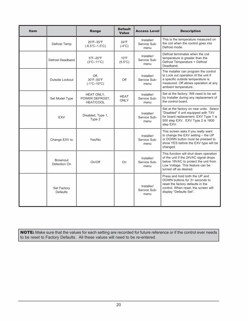
Defrost Temp 20°F–35°F(-6.5°C–1.5°C)
24°F (-4°C)
Installer/Service Sub-
menu
This is the temperature measured on the coil when the control goes into Defrost mode.
Defrost Deadband 5°F–20°F (3°C–11°C)
10°F (5.5°C)
Installer/Service Sub-
menu
Defrost terminates when the coil temperature is greater than the Defrost Temperature + Defrost Deadband.
Outside LockoutOff,
30°F–50°F(-1°C–10°C)
OffInstaller/
Service Sub-menu
The installer can program the control to Lock out operation of the unit if a specific outside temperature is measured. Off allows operation at any ambient temperature.
Set Model TypeHEAT ONLY,
POWER DEFROST, HEAT/COOL
HEAT ONLY
Installer/Service Sub-
menu
Set at the factory. Will need to be set by Installer during any replacement of the control board.
EXV Disabled, Type 1, Type 2
Installer/Service Sub-
menu
Set at the factory on new units. Select “Disabled” if unit equipped with TXV for board replacement. EXV Type 1 is 500 step EXV. EXV Type 2 is 1600 step EXV.
Change EXV to Yes/NoInstaller/
Service Sub-menu
This screen asks if you really want to change the EXV setting – the UP or DOWN button must be pressed to show YES before the EXV type will be changed.
Brownout Detection On On/Off On
Installer/Service Sub-
menu
This function will shut down operation of the unit if the 24VAC signal drops below 18VAC to protect the unit from Low Voltage. This feature can be turned off as desired.
Set Factory Defaults
Installer/Service Sub-
menu
Press and hold both the UP and DOWN buttons for 3+ seconds to reset the factory defaults in the control. When reset, the screen will display “Defaults Set”.
NOTE: Make sure that the values for each setting are recorded for future reference or if the control ever needs to be reset to Factory Defaults. All these values will need to be re-entered.

21
Table E: INSTALLER/SERVICE MENU — POWER DEFROST Configuration
Item Range Default Value Access Level Description
Set Current Time 12:00A–11:59P --- Installer
Selects current time – “A” or “P” will indicate whether the set time is AM or PM.
Pump Periods 0–4 Installer
Only available if Pump Operation in the Installer’s Menu is set to “4-Speed Enabled” or “Variable Enabled”.
Pump On Time 1 12:00A–11:59P --- InstallerSelect ON time for Pump Period #1 to take effect.
Pump Off Time 1 12:00A–11:59P --- InstallerSelect OFF time for Pump Period #1 to stop.
Pump Speed 11–4 if 4-Speed Enabled
0%–100% if Variable Enabled
Installer
On 4-speed pumps, this denotes the selected pump output (which connects to the pump for the selected speed) for this pump period. On Variable speed pumps, this denotes the PWM signal to be provided to the pump for pump operation.
Return Valve 1 Pool/Spa Pool Installer
Select the position of a 3-way valve located between the HPPH and the Pool/Spa for this scheduled pump period.
Suction Valve 1 Pool/Spa Pool InstallerSelect the position of the 3-way valve located between the Pool/Spa and the Pump for this scheduled pump period.
Pump On Time 2 12:00A–11:59P --- InstallerSelect ON time for Pump Period #2 to take effect.
Pump Off Time 2 12:00A–11:59P --- InstallerSelect OFF time for Pump Period #2 to stop.
Pump Speed 21–4 if 4-Speed Enabled
0%–100% if Variable Enabled
Installer
On 4-speed pumps, this denotes the selected pump output (which connects to the pump for the selected speed) for this pump period. On Variable speed pumps, this denotes the PWM signal to be provided to the pump for pump operation
Return Valve 2 Pool/Spa Pool Installer
Select the position of a 3-way valve located between the HPPH and the Pool/Spa for this scheduled pump period.
Suction Valve 2 Pool/Spa Pool InstallerSelect the position of the 3-way valve located between the Pool/Spa and the Pump for this scheduled pump period.
Pump On Time 3 12:00A–11:59P --- Installer
Select ON time for Pump Period #3 to take effect.

22
Item Range Default Value Access Level Description
Pump Off Time 3 12:00A–11:59P --- InstallerSelect OFF time for Pump Period #3 to stop.
Pump Speed 31–4 if 4-Speed Enabled
0%–100% if Variable Enabled
Installer
On 4-speed pumps, this denotes the selected pump output (which connects to the pump for the selected speed) for this pump period. On Variable speed pumps, this denotes the PWM signal to be provided to the pump for pump operation.
Return Valve 3 Pool/Spa Pool Installer
Select the position of a 3-way valve located between the HPPH and the Pool/Spa for this scheduled pump period.
Suction Valve 3 Pool/Spa Pool InstallerSelect the position of the 3-way valve located between the Pool/Spa and the Pump for this scheduled pump period.
Pump On Time 4 12:00A–11:59P --- InstallerSelect ON time for Pump Period #4 to take effect.
Pump Off Time 4 12:00A–11:59P --- InstallerSelect OFF time for Pump Period #4 to stop.
Pump Speed 41–4 if 4-Speed Enabled
0%–100% if Variable Enabled
Installer
On 4-speed pumps, this denotes the selected pump output (which connects to the pump for the selected speed) for this pump period. On Variable speed pumps, this denotes the PWM signal to be provided to the pump for pump operation.
Return Valve 4 Pool/Spa Pool Installer
Select the position of a 3-way valve located between the HPPH and the Pool/Spa for this scheduled pump period.
Suction Valve 4 Pool/Spa Pool InstallerSelect the position of the 3-way valve located between the Pool/Spa and the Pump for this scheduled pump period.
Faults Last Installer/Service
Fault history starting with the most recent and going back to 10 last faults. Using the UP/DOWN buttons scrolls through the fault history. If there are no faults present, the display will read “All Faults Clear”.
Clear Faults Installer/Service
Holding down the UP and DOWN buttons for 3+ seconds clears the recorded fault history and “Faults Cleared” appears on the display.
Run Hours XXXX Cycles XXXX
Installer/Service
Displays the number of run hours that the compressor has been running as well as the number of cycles that the unit has operated.

23
Item Range Default Value Access Level Description
VoltageUp/ Down for
More
Installer/Service
Press UP or DOWN buttons to access additional temperature measurements.
Voltage View Only – VAC --- Installer/Service
Displays the 24VAC voltage as measured by the control board.
Coil Temp View Only – degrees F or C
Installer/Service
Displays the coil temperature sensor value – used for defrost operation.
Amb Temp View Only – degrees F or C
Installer/Service
Displays the ambient temperature sensor value – used for Outside Lockout operation and defrost.
Suct Temp View Only – degrees F or C
Installer/Service
Displays the suction line temperature sensor value – used for EXV operation ONLY. Will not be shown if EXV Disabled is selected.
EXV Temp View Only – degrees F or C
Installer/Service
Displays the EXV temperature sensor value – ONLY available with EXV Enabled AND EXV Temp Sensor utilized. NOTE: This is ONLY utilized when the pressure transducer is NOT used.
Sat Temp View Only – degrees F or C
Installer/Service
Displays the pressure transducer converted to a temperature. It is displayed whenever EXV is enabled.
Water Temp View Only – degrees F or C
Installer/Service
Displays the water temperature sensor value – used for temperature operation
Installer Menu Yes or No No
Select YES and press the MENU button to gain access to additional programming selections in this Installer/Service Sub-menu. Select No and the next MENU button press returns to the Set Current Time screen.
Pump Operation4-Speed Enabled, Variable Enabled,
DisabledDisabled
Installer/Service Sub-
menu
If pump control through the HPPH is desired, select the appropriate pump mode – 4-Speed Enabled for discrete speed control or Variable Enabled for PWM control of pump.
Pump HeatInstaller/
Service Sub-menu
This feature selects the Digital input (pump speed) for the pump to operate during HPPH operation.
Valve Operation Enabled, Disabled DisabledInstaller/
Service Sub-menu
This feature allows control of 3-way valves. Disabled is the default. When Enabled, the control will seek information as to whether the Return and Suction valves should be positions for Pool or Spa positions for each pump period.
Return ValvePosition 1 = Pool/Spa Pool
Suction ValvePosition 1 = Pool/Spa Pool
AUX ModeAUX OFF, AUX
OUTPUT, REMOTE OUT, EXT HEAT
AUX OFFInstaller/
Service Sub-menu
See description of auxiliary mode operation on page 30.

24
Item Range Default Value Access Level Description
AUX1 On Time 12:00A-11:59P ---Installer/
Service Sub-menu
Select ON time for AUX1 to take effect.
AUX1 Off Time 12:00A-11:59P ---Installer/
Service Sub-menu
Select OFF time for AUX1 to stop.
AUX2 On Time 12:00A-11:59P ---Installer/
Service Sub-menu
Select ON time for AUX2 to take effect.
AUX2 Off Time 12:00A-11:59P ---Installer/
Service Sub-menu
Select OFF time for AUX2 to stop.
Defrost Temp 20°F–35°F (-6.5°C–1.5°C)
35°F (1.5°C)
Installer/Service Sub-
menu
This is the temperature measured on the coil when the control goes into Defrost mode.
Def Terminate 40°F–60°F ( 4°C–15.5vC)
50°F(10°C)
Installer/Service Sub-
menu
If the coil temperature reaches this setpoint, Defrost will terminate. Other Defrost algorithms are still operating behinds the scene.
Outside LockoutOff,
30°F–50°F (-1°C–10°C)
OffInstaller/
Service Sub-menu
The installer can program the control to Lock out operation of the unit if a specific outside temperature is measured. Off allows operation at any ambient temperature.
Set Model TypeHEAT ONLY,
POWER DEFROST, HEAT/COOL
HEAT/COOL
Installer/Service Sub-
menu
Set at the factory. Will need to be set by Installer during any replacement of the control board.
EXV Disabled, Type 1, Type 2 Disabled
Installer/Service Sub-
menu
Set at the factory on new units. Select “Disabled” if unit equipped with TXV for board replacement. EXV Type 1 is 500 step EXV. EXV Type 2 is 1600 step EXV.
Change EXV to Yes/NoInstaller/
Service Sub-menu
This screen asks if you really want to change the EXV setting – the UP or DOWN button must be pressed to show YES before the EXV type will be changed.
Brownout Detection On On/Off On
Installer/Service Sub-
menu
This function will shut down operation of the unit if the 24VAC signal drops below 18VAC to protect the unit from Low Voltage. This feature can be turned off as desired.
Set Factory Defaults
Installer/Service Sub-
menu
Press and hold both the UP and DOWN buttons for 3+ seconds to reset the factory defaults in the control. When reset, the screen will display “Defaults Set”.
NOTE: Make sure that the values for each setting are recorded for future reference or if the control ever needs to be reset to Factory Defaults. All these values will need to be re-entered.

25
Table F: INSTALLER/SERVICE MENU — HEAT/COOL Configuration
Item Range Default Value Access Level Description
Set Current Time 12:00A–11:59P --- Installer
Selects current time – “A” or “P” will indicate whether the set time is AM or PM.
Remote Pool Heat, Cool, Auto Cool InstallerSelects unit operation when controlled by remote.
Pump Periods 0–4 Installer
Only available if Pump Operation in the Installer’s Menu is set to “4-Speed Enabled” or “Variable Enabled”.
Pump On Time 1 12:00A–11:59P --- InstallerSelect ON time for Pump Period #1 to take effect.
Pump Off Time 1 12:00A–11:59P --- InstallerSelect OFF time for Pump Period #1 to stop.
Pump Speed 11–4 if 4-Speed Enabled
0%–100% if Variable Enabled
Installer
On 4-speed pumps, this denotes the selected pump output (which connects to the pump for the selected speed) for this pump period. On Variable speed pumps, this denotes the PWM signal to be provided to the pump for pump operation.
Return Valve 1 Pool/Spa Pool Installer
Select the position of a 3-way valve located between the HPPH and the Pool/Spa for this scheduled pump period.
Suction Valve 1 Pool/Spa Pool InstallerSelect the position of the 3-way valve located between the Pool/Spa and the Pump for this scheduled pump period.
Pump On Time 2 12:00A–11:59P --- InstallerSelect ON time for Pump Period #2 to take effect.
Pump Off Time 2 12:00A–11:59P --- InstallerSelect OFF time for Pump Period #2 to stop.
Pump Speed 21–4 if 4-Speed Enabled
0%–100% if Variable Enabled
Installer
On 4-speed pumps, this denotes the selected pump output (which connects to the pump for the selected speed) for this pump period. On Variable speed pumps, this denotes the PWM signal to be provided to the pump for pump operation
Return Valve 2 Pool/Spa Pool Installer
Select the position of a 3-way valve located between the HPPH and the Pool/Spa for this scheduled pump period.
Suction Valve 2 Pool/Spa Pool InstallerSelect the position of the 3-way valve located between the Pool/Spa and the Pump for this scheduled pump period.
Pump On Time 3 12:00A–11:59P --- Installer
Select ON time for Pump Period #3 to take effect.

26
Item Range Default Value Access Level Description
Pump Off Time 3 12:00A–11:59P --- InstallerSelect OFF time for Pump Period #3 to stop.
Pump Speed 31–4 if 4-Speed Enabled
0%–100% if Variable Enabled
Installer
On 4-speed pumps, this denotes the selected pump output (which connects to the pump for the selected speed) for this pump period. On Variable speed pumps, this denotes the PWM signal to be provided to the pump for pump operation.
Return Valve 3 Pool/Spa Pool Installer
Select the position of a 3-way valve located between the HPPH and the Pool/Spa for this scheduled pump period.
Suction Valve 3 Pool/Spa Pool InstallerSelect the position of the 3-way valve located between the Pool/Spa and the Pump for this scheduled pump period.
Pump On Time 4 12:00A–11:59P --- InstallerSelect ON time for Pump Period #4 to take effect.
Pump Off Time 4 12:00A–11:59P --- InstallerSelect OFF time for Pump Period #4 to stop.
Pump Speed 41–4 if 4-Speed Enabled
0%–100% if Variable Enabled
Installer
On 4-speed pumps, this denotes the selected pump output (which connects to the pump for the selected speed) for this pump period. On Variable speed pumps, this denotes the PWM signal to be provided to the pump for pump operation.
Return Valve 4 Pool/Spa Pool Installer
Select the position of a 3-way valve located between the HPPH and the Pool/Spa for this scheduled pump period.
Suction Valve 4 Pool/Spa Pool InstallerSelect the position of the 3-way valve located between the Pool/Spa and the Pump for this scheduled pump period.
Faults Last Installer/Service
Fault history starting with the most recent and going back to 10 last faults. Using the UP/DOWN buttons scrolls through the fault history. If there are no faults present, the display will read “All Faults Clear”.
Clear Faults Installer/Service
Holding down the UP and DOWN buttons for 3+ seconds clears the recorded fault history and “Faults Cleared” appears on the display.
Run Hours XXXX Cycles XXXX
Installer/Service
Displays the number of run hours that the compressor has been running as well as the number of cycles that the unit has operated.

27
Item Range Default Value Access Level Description
VoltageUp/ Down for
More
Installer/Service
Press UP or DOWN buttons to access additional temperature measurements.
Voltage View Only – VAC --- Installer/Service
Displays the 24VAC voltage as measured by the control board.
Coil Temp View Only – degrees F or C
Installer/Service
Displays the coil temperature sensor value – used for defrost operation.
Amb Temp View Only – degrees F or C
Installer/Service
Displays the ambient temperature sensor value – used for Outside Lockout operation and defrost.
Suct Temp View Only – degrees F or C
Installer/Service
Displays the suction line temperature sensor value – used for EXV operation ONLY. Will not be shown if EXV Disabled is selected.
EXV Temp View Only – degrees F or C
Installer/Service
Displays the EXV temperature sensor value – ONLY available with EXV Enabled AND EXV Temp Sensor utilized. NOTE: This is ONLY utilized when the pressure transducer is NOT used.
Sat Temp View Only – degrees F or C
Installer/Service
Displays the pressure transducer converted to a temperature. It is displayed whenever EXV is enabled.
Water Temp View Only – degrees F or C
Installer/Service
Displays the water temperature sensor value – used for temperature operation
Installer Menu Yes or No No
Select YES and press the MENU button to gain access to additional programming selections in this Installer/Service Sub-menu. Select No and the next MENU button press returns to the Set Current Time screen.
Pump Operation4-Speed Enabled, Variable Enabled,
DisabledDisabled
Installer/Service Sub-
menu
If pump control through the HPPH is desired, select the appropriate pump mode – 4-Speed Enabled for discrete speed control or Variable Enabled for PWM control of pump.
Pump HeatInstaller/
Service Sub-menu
This feature selects the Digital input (pump speed) for the pump to operate during HPPH operation.
Valve Operation Enabled, Disabled DisabledInstaller/
Service Sub-menu
This feature allows control of 3-way valves. Disabled is the default. When Enabled, the control will seek information as to whether the Return and Suction valves should be positions for Pool or Spa positions for each pump period.
Return ValvePosition 1 = Pool/Spa Pool
Suction ValvePosition 1 = Pool/Spa Pool
AUX ModeAUX OFF, AUX
OUTPUT, REMOTE OUT, EXT HEAT
AUX OFFInstaller/
Service Sub-menu
See description of auxiliary mode operation on page 30.

28
Item Range Default Value Access Level Description
AUX1 On Time 12:00A-11:59P --- Installer/Service Sub-menu Select ON time for AUX1 to take effect.
AUX1 Off Time 12:00A-11:59P --- Installer/Service Sub-menu Select OFF time for AUX1 to stop.
AUX2 On Time 12:00A-11:59P --- Installer/Service Sub-menu Select ON time for AUX2 to take effect.
AUX2 Off Time 12:00A-11:59P --- Installer/Service Sub-menu Select OFF time for AUX2 to stop.
Cooling Deadband 2°F–10°F(1°C–5.5°C)
6°F (3.3°C)
Installer/Service Sub-menu
In Pool Auto mode, the cooling setpoint is the heating setpoint minus this Cooling Deadband value.
Defrost Temp 20°F–35°F (-6.5°C–1.5°C)
35°F (1.5°C)
Installer/Service Sub-menu
This is the temperature measured on the coil when the control goes into Defrost mode.
Def Terminate 40°F–60°F (4°C–15.5°C)
50°F (10°C)
Installer/Service Sub-menu
If the coil temperature reaches this setpoint, Defrost will terminate. Other Defrost algorithms are still operating behinds the scene.
Outside LockoutOff,
30°F–50°F (-1°C–10°C)
Off Installer/Service Sub-menu
The installer can program the control to Lock out operation of the unit if a specific outside temperature is measured. Off allows operation at any ambient temperature.
Set Model TypeHEAT ONLY,
POWER DEFROST, HEAT/COOL
HEAT/COOL
Installer/Service Sub-menu
Set at the factory. Will need to be set by Installer during any replacement of the control board.
EXV Disabled, Type 1, Type 2 Disabled Installer/
Service Sub-menu
Set at the factory on new units. Select “Disabled” if unit equipped with TXV for board replacement. EXV Type 1 is 500 step EXV. EXV Type 2 is 1600 step EXV.
Change EXV to Yes/No Installer/Service Sub-menu
This screen asks if you really want to change the EXV setting – the UP or DOWN button must be pressed to show YES before the EXV type will be changed.
Brownout Detection On On/Off On Installer/
Service Sub-menu
This function will shut down operation of the unit if the 24VAC signal drops below 18VAC to protect the unit from Low Voltage. This feature can be turned off as desired.
Set Factory Defaults
Installer/Service Sub-menu
Press and hold both the UP and DOWN buttons for 3+ seconds to reset the factory defaults in the control. When reset, the screen will display “Defaults Set”.
NOTE: Make sure that the values for each setting are recorded for future reference or if the control ever needs to be reset to Factory Defaults. All these values will need to be re-entered.

29
The user can access these control settings by pressing and holding the MENU button for 5+ seconds. Any changes to values are stored into the non-volatile memory when the MENU button is pressed – which also toggles to the next setting. Failure to press any buttons for 60 seconds will cause the screen to revert back to its previous operating mode screen. However, the user mode can also be exited by pressing and holding the MENU button for 5+ seconds.
NOTE: See Table G on page 38 for Operational Status Messages that you may see during normal operation.
Set Current TimeThis allows setting of the current time. The time is followed by an “A” or “P” for AM and PM respectfully. The control has a 24-hour time clock – although it is NOT a 7-day time clock. The time clock is used for control of the pump periods and AUX1 & AUX2 times.
C/F DisplayThis setting is used to define the units of measure for all temperature readings. Fahrenheit is the default value. You can change the setting to Celsius by toggling the UP or DOWN button and then pressing the MENU button to lock in the change.
Spa Max TempThis setting is used to define the maximum temperature that the control can be set at for the Spa operation. The range is 65°F – 104°F (18°C – 40°C). The default value is 104°F (40°C).
Pool Max TempThis setting is used to define the maximum temperature that the control can be set at for the Pool operation. The range is 65°F – 95°F (18°C – 35°C). The default value is 95°F (35°C).
Pump PeriodsWhen the Pump Operation in the Installer’s Menu is set to “4-Speed Enabled” or “Variable Enabled”, this allows the setting of Pump Periods from this menu. When setting this parameter, the control displays “Pump Periods” on the first line of the display. The number of pump periods (0 – 4) is displayed on the center of the 2nd line. Pressing the UP or DOWN buttons increments/decrements the number of pump periods – factory default is 1. If a non-zero number of pump periods is selected when the MENU button is pressed, the control will prompt for On/Off times for each of the selected number of pump periods.
Temperature ControlThe control uses the appropriate Pool or Spa setpoint as selected in the Operating mode. The heat demand begins when the water temperature is 0.5°F (0.3°C) or more colder (or 0.5°F (0.3°C) or more hotter in cooling mode) than the setpoint.
Additional FeaturesPump ControlThe control is equipped to operate the system pump. The control provides for an output for a single speed pump (0.75A @ 24VAC maximum) as well as an output for a variable speed pump (10mA @12 VDC). Four signals are provided for selection of 4 discrete speeds for a variable speed pump. The control can be configured to provide a PWM signal on the speed1 output. The control will energize the pump at the requested speed for each of the pump periods set in the program mode. If a heat pump demand is present during a scheduled pump operation, the pump runs at the override speed (Speed 1) regardless of the scheduled speed. When the pump is active because of scheduled operation and there is no active heat demand, the control sets the 3-ways valve outputs to the states set in the program mode schedule.
Low Ambient (Outside) LockoutThe control is equipped with a Low Ambient Lockout feature which will prevent the start of a new cycle if the ambient temperature is lower than the programmed value. This feature is accessed through the Installer/Service Sub-menu as noted in INSTALLER/SERVICE menus on pages 17 - 28. The default value is “OFF”, but the temperature can be adjusted between 30°F and 50°F (-1°C and 10°C). This feature can be enabled if it is desired to not operate the unit if the temperature falls below this value. NOTE: This feature will NOT stop the operation of an existing cycle, it will only pre-vent operation of a new cycle.
An open ambient temperature sensor – display will read “Air Temp -46°F” (-43°C) – will trigger an “Outside Lockout” error if the Low Ambient lockout is enabled. A shorted – display will read “Air Temp 282°F” (139°C) – ambient temperature sensor will also cause the control to shut off the compressor regardless of if the Low Ambient lockout is enabled.
Control Lock Box ModeThe control is equipped with a Control Lockout feature which is accessed by pressing and holding the MENU and DOWN buttons for 5 seconds. The user will be prompted to enter a 3-digit code. A cursor flashes under each digit in the 3 digit code when that digit is being set. Pressing the UP or DOWN buttons increas-

30
es or decreases the value and press the MENU button to lock in that value. The cursor moves to the next digit for setting. Once the last digit is selected (pressing MENU) the display will ask to confirm the established Lockout code. Press UP or DOWN button until “YES” is shown and then press the MENU button to confirm this Lockout code.
NOTE: Record this Lockout code for future reference.
Pressing any button when the control is in Lockout Mode will prompt the user for the Lockout code. The display will read “Control Lockout – Enter PIN 000”. If the PIN is entered incorrectly, the display will show “Invalid PIN”. Pressing any button will return the user to the lockout code screen.
Entering the correct Lockout code will result in the display showing “Lockout Cleared” and the display will go to the current operating state of the unit.
Setting for total lockout operation without TIMED SPA operation (only recommended on systems with pool heat only):1. Press the MENU button until SPA is displayed.
2. Press the DOWN button until the setpoint temperature has been reduced to 65°F (18°C) or lower.
3. Press the MENU button for the next mode selection and set the desired setpoint temperature for each mode as appropriate.
4. Program the Control Lock Box mode as noted above.
AUX ModeThe control has the capability to control two auxiliary outputs for various external uses (rating is 0.75A @ 24VAC max.). There are 4 selectable modes within the Installer/Service Sub-menu for auxiliary mode control. These include: AUX OFF (default), AUX OUTPUT, REMOTE OUT, and EXT HEAT. The control allows setting ON and OFF times for these 2 auxiliary outputs in the Installer/Service Sub-menu.
1. AUX OUTPUT – When AUX OUTPUT is selected, the AUX1 and AUX2 outputs turn ON/OFF from the time schedule loaded into the control at installation. Time schedules for each output are independent of each other. If the OFF time is before the ON time, the control will assume the Aux output is to be energized over midnight. If the time of day is not known due to a clock failure, the AUX output schedules are not run.
2. REMOTE OUT – When REMOTE OUT is selected, the AUX1 output is used to control another pool heater (gas, HPPH or solar). This feature is ideal for when using a HEAT PUMP / GAS HEATER combo, where a Gas Heater will be providing ‘back up’ heating for your Heat Pump Pool Heater. Gas Heaters are usually used to assist when the temperature is too cold for a Heat Pump Pool Heater to heat the pool/spa water effectively on its own, or when the target temperature will require a larger amount of BTUs than what the Heat Pump Pool Heater can provide on its own, during a given time and/or outside conditions, in order to be achieved within the operator’s desired window of time. A Heat Pump Pool Heater, as the more efficient heating device when used in conjunction with a Gas Heater, should be the equipment in control of monitoring the pool/spa water temp and deciding whether there is a Call for Heat. In the REMOTE OUT mode, the ‘Ext. Heater’, i.e. Gas Heater, is not allowed to heat the water unless the Heat Pump Pool Heater is on as well.
To take advantage of this feature, set the Heat Pump Pool Heater to the desired Target Temp, and then set the Gas Heater to the temperature from which the Heat Pump Pool Heater will no longer truly need assistance. For example, if your dealer/installer’s calculations, or prior experience, determines that on your particular pool/spa, the Heat Pump Pool Heater will no longer need assistance getting the water to a desired temp of 80°F (27°C) once the water reaches 70°F (21°C), set the Heat Pump Pool Heater to 80°F (27°C) and the Gas Heater to 70°F (21°C).
The AUX1 output energizes 10 seconds after the first unit/Heat Pump Pool Heater’s compressor and de-energizes when the first unit/Heat Pump Pool Heater’s compressor de-energizes. AUX2 output is always OFF in this configuration.
REMOTE OUT (Multiple HPPHs) – The “Lead HPPH” can control one or more “follower HPPH” with a single set point temperature. The AUX1 output energizes 10 seconds after the “Lead HPPH” compressor and de-energizes after the “Lead HPPH” compressor de-energizes. AUX2 output is always OFF in this configuration.
3. EXT HEAT – When EXT HEAT is selected, AUX1 output is energized whenever there is a 1st stage heat demand. This allows the use of a solar system in conjunction with this unit and the control will operate the solar system first and only bring this unit on if the heating demand is NOT being met by the solar system. AUX2 is always off in this configuration.

31
The 2nd stage (HPPH) demand is initiated when water temperature has remained more than 0.5°F (0.3°C) colder than the heat setpoint for more than 2 hours, or when the water temperature is 1.5°F (0.8°C) or more colder than the heating setpoint.
Remote Pool OperationREMOTE Mode is accessed by pressing and holding the UP and DOWN buttons simultaneously for 3 sec-onds. When exiting the REMOTE mode, the control always selects the OFF Mode. If the UP, DOWN or MENU buttons are pressed while in REMOTE mode, the display will read “Exit Remote Mode to Adjust Temp”. Mode and temperature setpoints are not changed. Press and hold the UP and DOWN buttons for 3 seconds to exit REMOTE Mode.
On HEAT/COOL models, the control displays “Remote Pool” on the first line of the display while the 2nd line displays “Cool”, “Heat” or “Auto”. Factory default is “Cool”. The control uses the value selected when the MENU button is pressed to advance to the next item. This programming is done from the Installer/Service menus.
Pool Heat ModeThe control is equipped with a mode which will automatically heat the pool to the heating setpoint established in the User’s menu.
Pool Cool Mode (HEAT/COOL models ONLY)The control is equipped with a mode which will automatically cool the pool to the cooling setpoint established in the User’s menu.
Pool Auto Mode (HEAT/COOL models ONLY)The control is equipped with a mode which will auto-matically heat and cool the pool within the range of the heating setpoint plus the Cooling Deadband (2-10°F (1.1-5.5°C) adjustable – default 6°F (3.3°C)) estab-lished in the Installer/Service Sub-menu. Example – pool heating setpoint set at 80°F (27°C) and Cooling Deadband set at 6°F – unit will automatically heat the pool if the temperature drops below 80F (27°C) and will automatically cool the pool if the temperature is above 86°F (30°C).
TIMED SPA ModeThe control is equipped with a mode which will heat the spa to the Spa Setpoint temperature for a specified period of time selected in the TIMED SPA mode set-up. NOTE: The Spa setpoint temperature CANNOT be changed when operating in this mode. This func-tionality will override all other program settings for the period of time selected by the user during the TIMED SPA initiation.
WARNING: If the Spa heating (in a pool/spa system) is controlled by an external controller, 3-way valves MAY need to be manually adjusted in order to use the TIMED SPA feature of this HPPH. Failure to properly adjust the 3-way valves may result in overheating of the pool water or other undesirable results.
1. To activate the TIMED SPA feature, press the MENU button until “TIMED SPA” is displayed on the top line of the display.
2. Press the UP or DOWN buttons to select the desired duration of spa heating (up to a maximum duration of 6 hours in 15 minute increments).
3. The timer will start to count down from the selected period of time and the HPPH will operate to heat the spa water based on the previously selected spa setpoint temperature setting.
4. When the TIMED SPA timer has expired, the control will return to the previous mode that it was in when TIMED SPA was selected.
Fault HistoryThe control is equipped to maintain fault history in the Installer/Service menu. It will retain the last 10 faults (starting with the most recent). If the fault history exceeds 10 events, the earliest fault drops off when a new fault occurs. NOTE: There is no time/date stamp associated with each fault. This history is intended to simply show what faults the unit has experienced.
When the “Faults Last” shows on the display, press-ing the UP button toggles to the most previous fault. Pressing the UP button toggles through the recorded faults. The faults are labeled on the first line of the display as Faults Last, Faults 2, Faults 3, etc.
Consecutive identical faults are only stored once.
Run Hours/CyclesThe control is equipped to monitor the number of run hours of the unit and the cycles of operation. This is accessible through the Installer/Service menu. These values are not resettable. The “Run Hours” tracks the number of hours that the compressor has been energized. This data is stored in non-volatile memory each time the demand for heat is satisfied. Hours and minutes are stored, although only hours are displayed. The “Cycles” tracks the number of times that the com-pressor has been energized.

32
Compressor Start Delay The control is equipped with a compressor start delay to prevent short-cycling of the compressor. The control will not energize a compressor unless the compressor has been off for at least 3 minutes. When this situation arises, the display shall read “Comp Start Delay” until the timer clears and the compressor starts.
Minimum Run TimeTo ensure proper operation of the compressor and longest life, the control has a minimum run time for the compressor of 3 minutes. If the setpoint is reached within 3 minutes, the compressor will continue to run for 3 minutes unless (1) the high pressure switch trips, (2) the water pressure switch trips, (3) the high tem-perature limit is reached, or (4) the user selects “OFF” mode.
Defrost OperationThe control is equipped with several defrost algorithms depending on the configuration of the unit (HEAT ONLY, POWER DEFROST or HEAT/COOL).
On HEAT ONLY models, the control initiates a defrost cycle when the coil temperature falls to the “Defrost Temp” setpoint (24°F (-4.4°C) default) established in the Installer/Service sub-menu. The compressor will shut off, but the fan will continue to operate to pull warmer air across the coil in an effort to defrost the coil. When the control sees a rise in the coil sen-sor temperature equal to “Defrost Temp” + “Defrost Deadband” (10°F (5.5°C) default) or after 15 minutes have passed, the unit will exit the defrost cycle and will return to normal heating operation based on the current water temperature and setpoint temperature.
On POWER DEFROST models, the control initiates a defrost cycle when the coil temperature falls to the “Defrost Temp” setpoint (35°F (1.6°C) default) established in the Installer/Service sub-menu. The compressor will continue to operate (as well as the fan) and a solenoid valve will open allowing a portion of the hot refrigerant gas to bypass the heat exchang-er and be directed back to the coil to warm the coil for defrost. When the control see a rise in the coil temperature equal to the “Def Terminate” value estab-lished in the Installer/Service sub-menu (50°F (10°C) default), the solenoid valve will shut and the unit will return to normal heating operation based on the cur-rent water temperature and setpoint temperature.
On HEAT/COOL models, the control initiates a defrost cycle based on a programmed algorithm involving current and baseline ambient temperatures, and cur-rent and baseline coil temperatures when the coil temperature drops below the “Defrost Temp” set in the Installer/Service sub-menu. Factory default is 35°F
(1.6°C). The control shuts off the fan and activates the reversing valve so the hot refrigerant gas is directed to the coil to defrost the coil. When the coil sensor sees temperatures above the “Def Terminate” value set in the Installer/Service sub-menu, the unit returns to nor-mal operation based on the current water temperature and setpoint temperature.
NOTE: On Power Defrost and Heat/Cool models the initial defrost after power ON is a “sacrificial” defrost where the coil might freeze up more than expected. The control is learning the parameters of the installation to establish clear coil temperature conditions for future defrost operation.
3-Way Valve Control
NOTE: Pump operation must be enabled through Service/Installer Sub-Menu to operate 3-way valves - whether or not the HPPH control will actually control the pump or not.
The control is equipped to operate system 3-way valves. The control will set the 3-way valves to the state requested when there is an active thermostat demand for spa heat, pool heat or pool cool AND when Pump operation is enabled through the control. This takes priority over positions requested by Pump Schedule operations. If the control also operates the pump, the pump will shut off for 30 seconds before the valves change state so as to not have to fight pump head pressure during change of position. During this change, the display will show “Valve Chng Delay”.
The 3-way valves are field installed to the #38-40 & #41-43 terminals on the terminal strip inside the junction box of the unit. The initialization of the 3-way valves is set in the Installer/Service sub-menu.
If the water pressure switch (or water flow switch) is closed when the control needs to change the 3-way valve position, the control displays “WPS Closed” and waits indefinitely with the pump and compressor off until the water pressure switch (water flow switch) opens. After it senses the open switch, the control switches the 3-way valves and resumes normal oper-ation.
If no thermostatic demand is requesting operation and the pump is being run from scheduled pump periods, the control sets the 3-way valves to the states request-ed in the pump period mode schedule.
When there is no demand for pump output because of manually selected OFF mode, no thermostat demand or no scheduled pump period, the control leaves the 3-way valves in their last commanded state. Valve

33
Water Pressure SwitchThe control monitors the water pressure switch (or flow switch - if so equipped). If the pump has run for 3+ seconds, there is a demand for compressor and the water pressure switch is open, the control will prevent the compressor from running and show “Water PS Open” on the display. The water pressure switch is checked to ensure that it is open BEFORE allowing the 3-way valves to switch. This ensures that the pump is OFF before trying to change the 3-way valve positions.
Sequence of Operation1. Upon initial application of power, the HPPH control
briefly sets all segments on the LCD at power-up.
2. The control displays the current software revision and the model type configuration on the LCD for 2 seconds and then resumes the user selected mode it was in before power was interrupted.
3. Setpoints are read from non-volatile memory. If the checksum of the setpoints indicates corrupted values, “EEPROM Fault” is displayed on the LCD and operation is inhibited until setpoints are manually set.
4. If unit type has not been set (like during the replacement of the HPPH control), the control prompts the user to set the model type before any device operation is enabled.
5. Upon initial installation, there are several items that must be defined and programmed depending on the configuration and accessories intended to be controlled by the HPPH control. These include: (1) 3-way valve control (Yes or No), (2) Pump control (Yes or No and then what type of control – 4-speed control or variable speed control), (3) Auxiliary control (Yes or No and then what type – External Heat, Auxiliary Output or Remote Output).
6. Once these choices are made, then additional information relating to the establishing of pump periods, pumps speed during each period and Return/Suction Valve positions during each period must be determined and set in the control.
7. The options for the control can be very simple or quite complicated, depending upon the needs of the installation.
8. Once programming is completed, the control is ready for operation.
outputs will not change until there is an active request for them to be in a different state.
The rating of the control contacts is 0.75A at 24VAC maximum.
WARNING: If the Spa heating (in a pool/spa system) is controlled by an external controller, 3-way valves MAY need to be manually adjusted in order to use the TIMED SPA feature of this HPPH. Failure to properly adjust the 3-way valves may result in overheating of the pool water or other undesirable results.
Battery Back-upThe control is equipped with a battery to maintain con-trol settings through power outages. This is located on the upper right rear corner of the control. Replace as necessary with a BR2032, 3V battery.
High Water Temperature LimitThe control is equipped with a high water temperature limit which will shut off operation of the compressor if either water temperature sensor reads at or above 108°F (41°C). The display will read “Hi Water Temp”. The compressor will remain locked out until both sen-sors are below 103°F (40°C) and the user presses the UP button. The high temperature limit is active in all modes of operation.
High Pressure Switch LockoutIf the high pressure switch opens, the control de-en-ergizes the compressor output and the fan continues to run for 15 minutes after the HPS opened and the display will show “Hi Press Trip”. If the high pressure switch trips 7 times in a single cycle, the display will show “Hi Press Lockout” and the unit will be locked out of operation for 4 hours. The unit will automatically reset after 4 hours or the lockout can be manually reset by pressing the MENU button or cycling the power. The high pressure switch must close for 3 seconds for the control to recognize it as closed.
Low Pressure Switch LockoutThe control ignores an open low pressure switch for the first 30 seconds after the compressor is energized. If the low pressure switch opens for 3+ seconds any time after this 30 second period, the compressor will shut down and “Lo Press Trip” will show on the dis-play. If the low pressure switch trips 6 times in a single cycle, the display will show “Lo Press Lockout” and the unit will be locked out of operation for 4 hours. The unit will automatically reset after 4 hours or the lockout can be manually reset by cycling the power. The low pressure switch must close for 3 seconds for the con-trol to recognize it as closed.

34
9. The user may select “ON” for several operating modes depending on the unit type. Each mode is selected by pressing the MENU button to cycle between the modes. Each press of the MENU button selects the next mode. There is no automatic increment from continually pressing the MENU button. In fact, continually pressing the MENU button (for 3+ seconds) will move the user into the USER Menu.
10. For HEAT ONLY and POWER DEFROST models, the mode selections are OFF – POOL HEAT – SPA – TIMED SPA.
For HEAT/COOL models, the mode selections are OFF – POOL COOL – POOL HEAT – POOL AUTO – SPA – TIMED SPA.
11. REMOTE Mode is accessed by pressing and holding the UP and DOWN buttons simultaneously for 3 seconds. When exiting the REMOTE mode, the control always selects the OFF Mode.
12. If the UP, DOWN or MENU buttons are pressed while in REMOTE mode, the display will read “Exit Remote Mode to Adjust Temp”. Mode and temperature setpoints are not changed.
13. Press and hold the UP and DOWN buttons for 3 seconds to exit REMOTE Mode.
14. When operating, the unit will continue to operate until the water temperature is 0.5°F (0.3°C) above/below setpoint (below for cooling), until a defrost condition is needed or the unit is manually turned off.
15. The unit will remain in standby waiting for the next demand.
ControlsYour heat pump pool heater incorporates digital safety controls and indicators to ensure its safe, reliable operation.
Digital Water Temperature Control: The pool water temperature is controlled by the heat pump pool heater’s digital control system, which gives you the option of two settings: one for the desired spa temperature and the other for the desired pool temperature. Additionally, as mentioned earlier, the unit is compatible with most ‘2-wire’ and ‘3-wire’ control/automation systems.
Digital Controls Operating InstructionsThe electronic board has the capability of memorizing two different programmed temperature settings as follows:
• For a pool, maximum 95°F (35°C)
• For a spa, maximum 104°F (40°C)
To Increase or Decrease the Desired Water Temperature (Pool or Spa Mode)With the MENU in either Pool or Spa mode, simply press the UP or DOWN buttons to raise or lower the setpoint. Holding the UP or DOWN button will increment the setpoint 1 degree at a time, but continuing to hold either button will result in a “Speed-Up” mode which will increase the speed of number changes.
Select Temperature in °C or °FPress the MENU button for 3+ seconds to enter the USER Menu. Once in the USER Menu, toggle to the 2nd entry and using either the UP or DOWN buttons, change the temperature readings into °C or °F. When complete you can press and hold the MENU button for 3+ seconds to return to the operating mode or simply wait and the program will automatically return to the operating mode in 180 seconds.
Heat/Cool Operation Some models are equipped to provide both heating and cooling to the pool.
NOTE: Remove the pool/spa blanket and turn on any fountains, sprays or other water features and also run your system at nighttime to speed the cooling process.
When the unit has been operating in the heating mode for a few minutes, the discharge air temperature should be 8°–10°F (4.4°–5.5°C) cooler than the air entering the unit.
When the unit has been operating in the cooling mode for a few minutes, the discharge air temperature should be 8°–10°F (4.4°–5.5°C) warmer than the air entering the unit.
NOTE: Heating is more efficient during warmer day- light hours and cooling is more efficient during cooler nighttime hours.

35
Summer ShutdownIf you do not plan to use the heat pump pool heater during the summer months, secure and protect it as follows:1. Turn the unit circuit breaker or disconnect switch to
OFF.
2. Leave the valves set the way they are unless additional circulation is required. DO NOT stop all flow through the heat pump pool heater.
3. IMPORTANT: Remember to reset the valves before the next heating season, or the unit will not operate properly.
Freeze ProtectionIf the unit is installed in a location subject to freezing conditions, it is important to protect the water circuit from freezing, just as should be done for the pump and filter.
System Drain-Down1. Turn the unit circuit breaker or disconnect switch to
OFF.
2. With the pool pump OFF, close the external shut- off valves and remove the drain plugs located in the inlet and outlet water unions to allow water to drain.
Fig. 8: Drain Plugs Locations
Seasonal Start-Up or AnnualCheck
1. Remove leaves, pine needles, etc., from the evap- orator coil. Clean the coil by gently applying a mild solution of household liquid soap and water.
2. Remove the side louvered panels by removing the single screw at the top of each louvered panel. Lift and pull the bottom out. The panel will easily come away from the cabinet giving access to the coil for cleaning.
3. Gently rinse the coil with water; DO NOT use high pressure.
4. Re-install the side louvered panels and secure each with the single screw at the top center of each panel.
5. Backwash or otherwise clean the pool filter. If necessary, clean the skimmer basket and pump strainer.
6. Set the valves to ensure proper water flow through the unit.
NOTE: At the beginning of the heating season or whenever the pool water temperature is to be raised several degrees, the pool pump and heat pump pool heater may need to operate continuously for several days. During summer months, only a few hours per day may be necessary or none at all.
NOTE: If the pool pump and heat pump pool heater shut OFF before the water temperature is raised to the desired level, you must lengthen the running time of both. To do this, reset the time clock dial for the longer running time, or manually operate the pump with the timer override switch. Since the heat pump pool heater capacity and efficiency are both greater at higher ambient air temperatures, run time should be set to take advantage of all daylight hours, when the air is generally warmer.
System Start-Up1. Verify that the Digital Board is displaying a
temperature and the pool pump is running and water is circulating properly.
2. Verify that the Board is programmed so that the desired temperature of the Pool and/or Spa is higher than the displayed current water temperature.
3. Allow the heat pump pool heater to operate for a few minutes to stabilize operating pressures and to allow various component temperatures to normalize.
4. Verify that the discharge air temperature is approximately 8°–10°F (4.4°–5.5°C) cooler than the air entering the unit (in heating mode). If not, see the Troubleshooting Section.

36
3. Use a wet/dry vac or air pressure to remove excess water - as necessary.
4. Once the water is drained, reinstall the drain plugs.
5. Cover the unit with a waterproof cover.
Continuous Pump OperationIt is also possible in some areas to prevent unit freeze damage by operating the pump continuously during freezing weather. However, this results in significantly higher pump operating costs. Further, if a sustained power failure occurs, the unit MUST be drained any- way, or freeze damage could result.
NOTE: The heat pump pool heater MANUFACTURER IS NOT RESPONSIBLE for maintenance adjustments.
MaintenanceThe following maintenance procedures are designed to keep your unit operating at a high level of reliability. Maintenance must be performed on a periodic basis to maintain warranty coverage and prevent system failures and performance degradation.
CAUTION: To clean the fins, remove the side louvered panels and spray gently with a garden hose. DO NOT pressure wash. Doing so will bend the fins and can void the warranty.
Air Coil CleaningEfficient operation depends on free circulation of air through the thin and tightly-spaced fins of the evaporator coil(s). The evaporator must be cleaned whenever it has a buildup of dirt or debris.
Cabinet Care (optional)
WARNING: Shut OFF electricity to the unit before cleaning.
The powder coated cabinet is designed for outdoor use and requires little care. However, you can clean it if you wish. Wash the cabinet with soap and water.
Unplug Condensation Drain HolesThe unit extracts humidity from the air as it passes through the coil, similar to the way a cold drink outside “sweats” on a hot day. This condensation drains from the bottom of the unit.
1. Routinely check to be sure the condensation drain holes in the base of the unit are not plugged with dirt or debris. See Fig. 9 for condensate drain hole locations.
2. If condensation becomes a problem, optional drain pans may be available from your heat pump pool heater distributor or pool dealer.
TroubleshootingIf your unit does not operate, or simply does not heat your pool water, Fault Messages on the front control panel can provide valuable clues as to what is wrong, and may even indicate precisely what the problem is. Always observe these messages before calling a service representative. By reporting on the telephone the Fault Messages that are showing, the service rep may be able to solve the problem without the expense of a service call.
A. UNIT IS RUNNING, BUT NOT HEATING• Is water flow through the unit adequate? Check the
unit for obstructions, such as a clogged filter pump strainer, a dirty filter, or valves not positioned correctly.
• Is the ejected air from the unit 8°–10°F (4.4C–5.5C) cooler than incoming air? If so, the unit is extracting heat from the air and transferring it to the pool.
• Is water condensing on the evaporator and internal copper pipes? This is also evidence of heat removal from the air. When the air is cool with low humidity, condensation may not be evident.
• How long has the unit been operating? During initial pool heating in cold weather, it may require a week to elevate the water temperature to a comfortable level. Normally, it takes about 4 days.
DRAINHOLES
Fig. 9 : Condensate Drain Hole Locations

37
How many hours per day is the unit operating? Remember that the heat pump pool heater only operates while the pool pump is running. Set the time clock to permit 24 hour per day operation. After the desired temperature is reached, return the unit to normal operation of 8–10 hours per day.
NOTE: If the pool pump and heat pump pool heater shut OFF before the water temperature is raised to the desired level, you must lengthen the running time of both. To do this, reset the time clock dial for the longer running time, or manually operate the pump with the timer override switch. Since the unit capacity and efficiency are both greater at higher ambient air temperatures, run time should be set to take advantage of all daylight hours, when the air is generally warmer.
• Is airflow through the unit being obstructed? Restrictions such as shrubbery, tall grass, dirty coils, or any other obstruction to airflow will reduce performance.
• Is the pool blanket/cover being used? Unblanketed pools can lose up to 10°F (5.5°C) per night compared to 4°F (2.2°C) or fewer when a blanket is used. Without a blanket, the total heat gained during the day can be lost overnight.
• Are rapid heat losses occurring in some other way, such as high wind, spillage, rainfall, flow through solar panels at night, or a high water table?
B. UNIT IS NOT RUNNING• Is the temperature display ON? If not, the circuit
breaker may be shut OFF or tripped. Reset the breaker by switching it OFF, and then back ON. Verify that the breaker is set and operating properly before calling for service.
• Are the Pool/Spa settings correct? Verify that the temperature has been properly set on the thermostat, and that it is higher than the current water temperature.
• Have you waited approximately 5 minutes for the time delay? After the unit has been running and then shut OFF for any reason, there is a delay before operation can begin again. The display will read “Comp Start Delay” when this 5 minute delay is active.
NOTE: The heat pump pool heater will not run when the Remote position is selected on the Pool/Spa control and there is no remote control system attached.
C. CONDENSATION SEEMS EXCESSIVEHeat pump pool heaters can produce a large amount of condensation (water) during operation. If you suspect that the unit is leaking:
• Shut the unit OFF and leave the filter pump running to see if the water stops dripping. If the water stops dripping, the unit is not leaking.
NOTE: Use a pool chemistry test kit to confirm there is no chlorine in the water.

38
TroubleshootingBefore troubleshooting the system, ensure that:
• All mechanical and electrical connections are secure and tight
• All system wiring is correct
• Fuse is not blown (3A Automotive “ATO” type fuse for 24VAC)
• That a system ground is properly connected to the heater. Nuisance shutdowns are often caused by a poor or erratic ground.
The service display can be accessed by pressing and holding the UP and MENU buttons for 3+ seconds. The service display does not affect operation of the unit which continues to operate in the background. When in this mode, pressing the UP or DOWN buttons will toggle through the various information reported. Some items (Fault History and Sensor Temperatures) have multiple values (press UP or DOWN buttons to scroll through the additional information). The service display mode may be exited to return to the previous display be pressing the UP and MENU buttons or it will automatically be exited if no button is pressed within 60 seconds.
The following operational status messages are displayed in Pool, Spa, and Remote operating modes.
Table G: Operational Status Messages
Message Description Recommended Troubleshooting
Comp Start Delay Notification that the compressor is under a 3-minute delay before turning On. This can be bypassed by pressing the UP and DOWN buttons simultaneously.
Nothing wrong – just notification as to why the unit is not currently operating.
Valve Chng Delay Notification that the 3-way valves are being commanded to change positions Pool to Spa or Spa to Pool.
Nothing wrong – just notification as to why the unit is not currently operating.
WPS Closed 3-way valves not switched because water pressure switch still closed.
Check settings – pump operation Disabled?
Defrost Unit is performing a Defrost cycle. Nothing wrong – just notification as to why the unit is not currently operating.
Heating Unit is operating and running a heating cycle.
N/A
Cooling Unit is operating and running a cooling cycle.
N/A
External Heat The AUX Mode setting is set to EXTERNAL HEAT meaning an external device (solar heating system) is running 1st stage instead of the heat pump.
Verify desired settings.
Outside Lockout The compressor is not running because the ambient temperature is too cold as measured by the Ambient sensor.
Verify Outside Lockout temperature setting.Check Amb Temp sensor value in Installer sub-menu and replace if value is inconsistent with ambient temperatures.Disable this function in the Installer/Service sub-menu if Outside Lockout is not desired.
No Demand Demand has been satisfied and the unit is in standby.
N/A

39
The following error messages are displayed in Pool, Spa, and Remote modes. Consecutive identical faults are only stored once in the Fault History.
Table H: Error Messages
Error Message Description Troubleshooting
Amb Sensor Fail Ambient temperature sensor is OPEN or SHORTED.
Replace Amb Temperature sensor.
Coil Sensor Fail Coil temperature sensor is OPEN or SHORTED.
Replace Coil Temperature sensor.
H2O Sensor Fail Water temperature sensor is OPEN or SHORTED.
Replace Water Temperature sensor.
Aux Sensor Fail AUX temperature sensor is OPEN or SHORTED (if equipped).
Replace AUX Temperature sensor.
Hi Press Trip High pressure switch is preventing compressor from operating.
Check High Pressure switch operation – replace as necessary.
Lo Press Trip Low pressure switch is preventing compressor from operating.
Check Low Pressure switch operation – replace as necessary.
Hi Press Lockout High pressure switch has tripped 7 times in a single thermostat demand cycle.
The compressor is locked out of operation for 4 hours with an auto reset. However, this lockout time can be reset by pressing the MENU button or cycling the power.Check refrigerant charge and adjust as necessary.Check for low water flow.
Lo Press Lockout Lo pressure switch has tripped 6 times in a single thermostat demand cycle.
The compressor is locked out of operation for 4 hours with an auto reset. However, this lockout time can be reset by pressing the MENU button or cycling the power.Check refrigerant charge and adjust as necessary.
Brownout Compressor not operating due to low 24VAC power supply.
Voltage must be greater than 17VAC for 4+ seconds before compressor operation is enabled. Check supply power to unit and check 24VAC from transformer. Replace/correct as necessary.
Hi Water Temp Water temperature sensor reads at or above 108°F (42°C). Compressor is prevented from operating.
Temperature measured on water sensor must be below 103F AND the UP button MUST be pressed to reset this alarm.
Remote Error Both Spa and Pool inputs energized. Check wiring of remote to the terminal blocks.
Water PS Open Water flow or water pressure switch is open. Check water flow.Check settings for Pump Operation.
Outside Lockout The ambient temperature is lower than the programmed temperature for lockout.
Check Amb sensor – might be OPEN or SHORTED.Change Outside Lockout setting on control – change temp setting or set to OFF to disable Outside Lockout.Wait until ambient temperature rises above setpoint established in installer/service mode.
Control Fault 1 Compressor relay failure. Auto reset in 1 hour or Recycle control – replace control if fault continues.
Control Fault 2 ROM CRC Failure. Auto reset in 1 hour or Recycle control – replace control if fault continues.
Control Fault 3 RAM Failure Auto reset in 1 hour or Recycle control – replace control if fault continues.
Control Fault 4 Software Execution Out of Sequence Auto reset in 1 hour or Recycle control – replace control if fault continues.
Control Fault 5 Analog to Digital Converter Failure Auto reset in 1 hour or Recycle control – replace control if fault continues.
Control Fault 6 Analog to Digital Multiplexer Failure Auto reset in 1 hour or Recycle control – replace control if fault continues.

40
Error Message Description Troubleshooting
Control Fault 7 Interrupt Error. Auto reset in 1 hour or Recycle control – replace control if fault continues.
Control Fault 8 Time of Day Clock Failure. If the control is unable to read the time of day clock, it logs the fault and disables scheduled pump and aux output settings. Time is displayed as ??:?? in this condition. Recycle control – replace control if fault continues.
Service Call Verification
Before you make a service call, first determine if the problem is:
• Warranty Service - must have model number, serial number and date of installation or Warranty Registration confirmation number.
• Unit operation (power supply, water flow, or time clock adjustment)
Power Supply• Verify that all circuit breakers are reset and
working properly.
• If the temperature display on the control panel still does not light, contact the installing dealer, since it may be a power problem requiring an electrician.
Water Flow• Verify that the pool filter is clean to provide good
flow.
• Verify that valves are properly positioned to allow adequate water flow through the unit.
Time Clock AdjustmentVerify that the time clock is set to permit the unit to run long enough to heat properly.
Set Factory DefaultsIf programming is messed up and no operation can reliably be made, the control board can be reset to Factory Default values as noted in Table D, E or F. This operation changes all adjustable settings to factory default settings. Enter the Installer/Service Mode by holding the MENU and UP buttons for 3+ seconds. Scroll through the information until you reach the “Installer Menu” screen
NOTE: The MANUFACTURER IS NOT RESPON- SIBLE for these adjustments.
NOTE: The Service number is located on the front of the HPPH at the brand label.
- press the UP or DOWN button until YES appears on the 2nd line. Press the MENU button to access the additional Service information. Continue to press the MENU button until “Set Factory Defaults” appears on the display. Press and hold the UP and DOWN button for 5 seconds to reset the control to factory defaults. The display will read “Defaults Set” when completed.
Service Access to Heaters
If service access to the heater is required, it is accomplished by removing the control panel to provide a wide access to get to (1) compressor, (2) heat exchanger, (3) TXV, (4) reversing valve/solenoid valve (if equipped), (5) flow switch (if equipped), and (6) sensors (water, ambient and coil). To gain access, follow the steps below:1. Shut off all power to the unit to avoid any possibility
of electrical shock or damage to components.
2. Remove the 5 screws securing the control panel cover from the cabinet (2 each side and 1 in the top panel – see Fig. 10 below). Place the screws in the recessed cups in the molded base.
NOTE: Previous settings will be erased and are no longer recoverable. All settings will have to re-entered by hand to re-establish proper operation.
Fig. 10: Sheet Metal Screws to Remove Control Panel

41
3. Remove the multi-pin connectors from the back of the control board (8 connectors in total) – NOTE: You do not need to remove the PL4 connector as this is the ribbon cable from the membrane switch mounted on the control panel.
4. Set the control panel cover aside to reinstall when service is completed.
5. Remove the 4 screws securing the junction box panel to the cabinet (1 each side and 2 by Inlet/Outlet water connections). See Fig. 11. Place the screws in the recessed cups in the molded base.
6. Remove the 2 screws holding the compressor wire retainer to the junction box and place them in the recessed cups in the molded base.
7. Slide the compressor wires out the side of the slot in the junction box.
8. Lift the junction box slightly (hold onto the bottom of the junction box like a handle) and pull out at the bottom to remove the junction box assembly.
WARNING: Care must be taken with the fan and compressor wires when removing junction box.
9. Slide assembly away from the opening to give access inside the unit. NOTE: The top of the unit may also be removed for greater access as desired.
Fig. 11 : Sheet Metal Screws to remove Junction Box Panel
10. After service, reposition the junction box and insert the top first and lift up until the bottom slides into place against the cabinet and the panel where the Inlet/Outlet water connections are secured.
11. Reinstall the compressor wire retainer to the junction box with the 2 screws removed in Step #6.
12. Reinstall the screws removed in Step #5 to secure the junction box to the cabinet.
13. Reconnect the multi-pin connectors to the control board.
14. Slide the control box cover into place and secure with the screws removed in Step #2.
15. Turn ON power and start operation as needed.
CAUTION: Ensure that the fan motor wires are routed into the slot at the top of the junction box. Also ensure that the compressor wires are routed into the slot on the right side of the junction box.
WARNING: If any wires have come off components during service of this unit, please refer to the wiring diagram on the back of the control panel cover or in the I&O manual to ensure that they are returned to the correct terminals/locations.

42
Plumbing Diagrams
WAT
ER O
UT
(TO
PO
OL
OR
SPA
)
CH
EMIC
ALIN
TRO
DU
CTI
ON
CH
ECK
VALV
E
FILT
ER
WAT
ER IN
(TO
PO
OL
OR
SPA
)
Fig. 12: Plumbing Schematic – No External Bypass (Plumb the heat pump pool heater AFTER the filter and BEFORE any chlorinators.)
NO
TE
: M
odel
s 24
50-4
450
– Fo
r sys
tem
s w
ith p
umps
less
than
1-1
/2 H
P (u
nder
40
gpm
/ 15
1 lp
m)
Mod
els
5450
-845
0 –
For s
yste
ms
with
pum
ps le
ss th
an 2
HP
(und
er 8
0 gp
m /
303
lpm
)
N
o ex
tern
al b
ypas
s re
quire
d.

43
WAT
ER O
UT
(TO
PO
OL
OR
SPA
)
CH
EMIC
ALIN
TRO
DU
CTI
ON
CH
ECK
VALV
E
FILT
ER
WAT
ER IN
(TO
PO
OL
OR
SPA
)
Fig. 13: Plumbing Schematic – External Bypass (Plumb the heat pump pool heater AFTER the filter and BEFORE any chlorinators.)
NO
TE
: M
odel
s 24
50-4
450
– Fo
r sys
tem
s w
ith p
umps
of 1
-1/2
HP
or g
reat
er (o
ver 4
0 gp
m /
151
lpm
)
M
odel
s 54
50-8
450
– Fo
r sys
tem
s w
ith p
umps
of 2
HP
or g
reat
er (o
ver 8
0 gp
m /
303
lpm
)
E
xter
nal b
ypas
s re
quire
d. A
djus
t the
byp
ass
valv
e to
div
ert a
min
imum
of 2
0 gp
m /
76 lp
m (2
450-
4450
)
or
30
gpm
/ 11
4 lp
m (5
450-
8450
) thr
ough
the
heat
pum
p po
ol h
eate
r.

44
Fig. 14: Pool Piping for Heat Pump Pool Heater and Gas Pool Heater

45
Fig. 15: Pool Piping for Heat Pump Pool Heaters, Multiple, Primary/Secondary
EX
TE
ND
12
” P
AS
TH
EA
TE
R IN
LE
T F
OR
HY
DR
AU
LIC
BA
LA
NC
ING
.
2450-4450
BR
AN
CH
MA
INB
RA
NC
HM
AIN
BR
AN
CH
MA
IN20
GP
M1-
1/2"
1-1/
2"20
GP
M1-
1/2"
1-1/
2"20
GP
M1-
1/2"
2"30
1-1/
2"1-
1/2"
301-
1/2"
2-1/
2"30
1-1/
2"3"
401-
1/2"
2"40
1-
1/2"
3 *S
izin
g ba
sed
on10
ft/s
ec fl
ow ra
tes
MIN
IMU
M P
IPE
SIZE
S2
UN
ITS
3-4
UN
ITS
5-6
UN
ITS
5450-8450
BR
AN
CH
MA
INB
RA
NC
HM
AIN
BR
AN
CH
MA
IN30
GP
M40 60 80
2" 2" 2" 2"
2" 3" 3" 4"
30 G
PM
40 60 80
2" 2" 2" 2"
2-1/
2"3" 4" 4"
30 G
PM
40 60 80
2" 2" 2" 2"
4" 4" 5" 5"
MIN
IMU
M P
IPE
SIZE
S2
UN
ITS
3-4
UN
ITS
5-6
UN
ITS
40
1-1/
2"4"

46
Wiring Diagram — 208V/230V Single-Phase — Digital Models
NC NO COM L1 L2 L2
BK (TO TRANSFORMER)
RBK
L2L1
INSERT A
VOLTAGEMONITOR
WBLBKOR
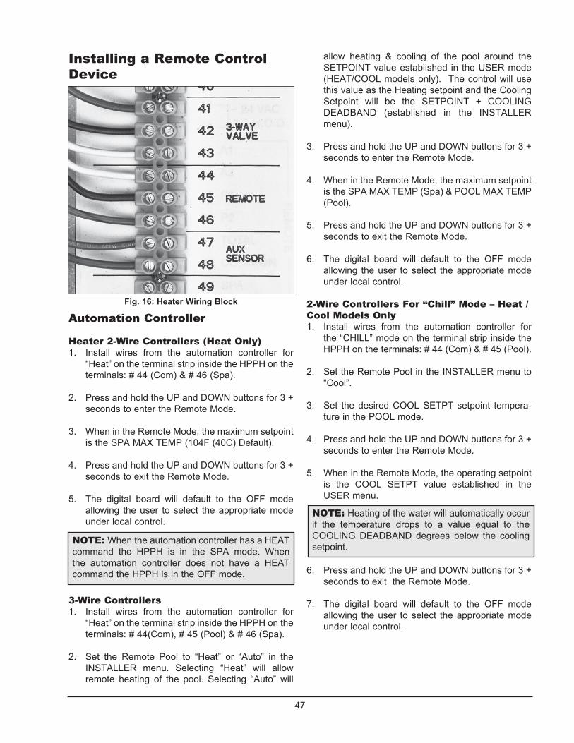
47
Installing a Remote Control Device
Automation Controller
Heater 2-Wire Controllers (Heat Only)1. Install wires from the automation controller for
“Heat” on the terminal strip inside the HPPH on the terminals: # 44 (Com) & # 46 (Spa).
2. Press and hold the UP and DOWN buttons for 3 + seconds to enter the Remote Mode.
3. When in the Remote Mode, the maximum setpoint is the SPA MAX TEMP (104F (40C) Default).
4. Press and hold the UP and DOWN buttons for 3 + seconds to exit the Remote Mode.
5. The digital board will default to the OFF mode allowing the user to select the appropriate mode under local control.
3-Wire Controllers1. Install wires from the automation controller for
“Heat” on the terminal strip inside the HPPH on the terminals: # 44(Com), # 45 (Pool) & # 46 (Spa).
2. Set the Remote Pool to “Heat” or “Auto” in the INSTALLER menu. Selecting “Heat” will allow remote heating of the pool. Selecting “Auto” will
Fig. 16: Heater Wiring Block
allow heating & cooling of the pool around the SETPOINT value established in the USER mode (HEAT/COOL models only). The control will use this value as the Heating setpoint and the Cooling Setpoint will be the SETPOINT + COOLING DEADBAND (established in the INSTALLER menu).
3. Press and hold the UP and DOWN buttons for 3 + seconds to enter the Remote Mode.
4. When in the Remote Mode, the maximum setpoint is the SPA MAX TEMP (Spa) & POOL MAX TEMP (Pool).
5. Press and hold the UP and DOWN buttons for 3 + seconds to exit the Remote Mode.
6. The digital board will default to the OFF mode allowing the user to select the appropriate mode under local control.
2-Wire Controllers For “Chill” Mode – Heat /Cool Models Only1. Install wires from the automation controller for
the “CHILL” mode on the terminal strip inside the HPPH on the terminals: # 44 (Com) & # 45 (Pool).
2. Set the Remote Pool in the INSTALLER menu to
“Cool”.
3. Set the desired COOL SETPT setpoint tempera-ture in the POOL mode.
4. Press and hold the UP and DOWN buttons for 3 + seconds to enter the Remote Mode.
5. When in the Remote Mode, the operating setpoint is the COOL SETPT value established in the USER menu.
NOTE: Heating of the water will automatically occur if the temperature drops to a value equal to the COOLING DEADBAND degrees below the cooling setpoint.
6. Press and hold the UP and DOWN buttons for 3 + seconds to exit the Remote Mode.
7. The digital board will default to the OFF mode allowing the user to select the appropriate mode under local control.
NOTE: When the automation controller has a HEAT command the HPPH is in the SPA mode. When the automation controller does not have a HEAT command the HPPH is in the OFF mode.

48
100K sensors are used for water temperature measurement. These sensors are dual thermistors in a single sensor housing. The control uses both sensor reading in operating the unit. If the control measures temperatures on these thermistors which are approx. 3°F (1.6°C) apart, the control will shut off the compressor and show “H2O Sensor Fail”.
The message will be cleared and operation resume when thermistors are within 2°F (1.1°C) of each other. The sensor has a measurement error of less than +/- 0.5°F (0.3°C) between 36°F and 110°F (2.2°C and 43°C) temperatures. The control displays 100K sensor temperatures to 0.1°F or 0.1°C resolution. The water temperature used for thermostat decisions is the average of the 2 thermistors.
10K sensors are used for the Ambient Air Temperature sensor, the Coil Temperature sensor and Aux Heat Temperature sensor (field supplied when necessary). The sensor has a measurement error of less than +/- 0.5°F (0.3°C) between 36°F and 110°F (2.2°C and 43°C) temperatures. The control displays 10K sensor temperatures to 0.1°F or 0.1°C resolution.
Table I: Sensor Values
Temperature ºF (ºC) Resistance (Ω)
32 (0) 32550
41 (5) 25340
50 (10) 19870
59 (15) 15700
68 (20) 12490
77 (25) 10000
86 (30) 8059
95 (35) 6535
104 (40) 5330
113 (45) 4372
122 (50) 3605
Temperature ºF (ºC) Resistance (Ω)
32 (0) -----
41 (5) 253950
50 (10) 199040
59 (15) 157150
68 (20) 129440
77 (25) 100000
86 (30) 80570
95 (35) 65310
104 (40) 53260
113 (45) 43680
122 (50) 36020
Other Sensors 10K Sensor Resistance Values
Water Sensor 100K Sensor Resistance Values
Resistance Sensor Values

49
NOTES

50
NOTES

51
NOTES

Raypak, Inc., 2151 Eastman Avenue, Oxnard, CA 93030 (805) 278-5300 Fax (805) 278-5468Heat Pump Service 1-800-260-2758
Litho in U.S.A.