heat setting procedures for helical q … as weri the music wire springs. test data for the chrome...
TRANSCRIPT
R-TR-76-044
/1/0*
HEAT SETTING PROCEDURES FOR HELICAL
Q COiLED SPRINGS
HENRY P. SWIESKOWSKI
DECEMBER 1976
FINAL REPORT
RESEARCH DIRECTORATE
! ~ Approved fo~r public release; distribution unl.mdecd.
"" GfRAL THOMAS J. RODMAN LAIORATORYROCK ISLAND ARSENAL
ROCK ISLAD, ILLINOS 61201
xw7777n 777m

DISPOSITION INSTRUCTIONS:
Destroy this report when it is no longer needed. Do notreturn it to the originator.
DISCLAIMER:
The findings of this report are not to be construed asan official Department of the Army position unless sodesignated by other authorized documents.
UNILASSI!EDSECURITY CLASSIFICATION OF THIS PAGE ("?Ien Date EntOrve,
I READ IN4STRUCTIONSREPORT DOCUMENTATION PAGE BEFORE C0RPLECTING FORM
. .. RT''7'--&4 / "2. OVI ACCESSION NO. 3. RECIPIHT*S CAT..LOG NUMBER
S TYPE OF REPORT & PERIOD COVERED
SEII•GtiG. 5. IFRFORMING ORG. REPORT NUMBER
7. AUTHOR(a) I--ýGA UBR.
9. PERFORMING OGANIZATION NAME AND ADDRESS ' 10 PIOGR Xw ELL.ENT. PROJECT. TASK•FARCH DLREfPATE, WORK UNIT NUMBERS
GZ- THOMAS J. RODMAN LABOPATORY AJ.1cM 3297.o6.7431RO-CK ISUA1D AFGENA3A, ROC ISuuND, i. 1o ___________
$1 CONJTROLLING OFFICE NAME AND ADDRESS
OCDR, ROCK ISLAND ARSENAL |/7GEN THOMAS J. RODMAN LABORATORY, SARRI-RLR ti"
ROCK ISLAND, IL 61201 29_ _14 MONITORING AGENCY NAME & AODOrESS(If jtflate•f,,"• C"ontpolit Office) IS SECURITY CLASS (of this report)
/ 15a. DECLASSIFICATION/OOWNGRADINGSCHEDULE
16, DISTRIBUTION STATEMENT (of this Report)
APPROVED FODR PUBLIC RELEASE, DISTRIBUT~ION UNLflITED.
17 DISTY IBUTIOII STATEMENT (of the a•h tract m itered In Block 20, I f different fro m Rc, vrt) ..
1S SUPPLEMeNTARY NOTES
I9. KEY WORDS (Continue on reverse side if nec.eary an i,: Idznti•v ry block number)
I-AT SE'VTINGMAI'IFAC•'1'UING PROCEDURESHELICAL SPRINGSLOAD RETENTION' E3DUFANCE TESTS
20. A1S RACT (Continua on rav.,rae aide If necessary and Identify by blor.% number)
--- Various heat setting procedures for the manufacture of helical compressionsprings were in:estigated to determine optimus heat setting methods that willminimize operational spring set and load losses. Production springs werefabricated from misic wire, stainless steel and chromie vanadiun materials. Thesprings were given heat set.ing treatments under Ii>:•- ... o -t~~~~ ..... tel-t ncL1-conditions of ten-p-eratures, time durations and stress levels, Effects of the various heat setti
procedures on spring set and ý.oad reductions were evaluated by laboratory
FORMDD I jAN 73 1473 EDITION OF NOVr65 IS ODsW'F.TF R. \SSIFI
SECURITY CLASSIFICATION OF THIS PAGE (When Data Entered)
<..:¢•) - --

SEC•*•UTY•, 4ASSIFICATIOW•0F THIS PAGE(1fhn Date Entered)
ABSTACT - cont.
endurance tests. lecomended heat setting procedures based on study nrisultsare given for the spring materials and test conditions investigated in thisproject.
41'
//
1<
UNCIASSIFIESECURITy CLASSIFICATION OF THI:; P.GEM(h, Dat .te Entered)
=R
Contents
DD Form 1473 i
Contents iii
Objectives 1
Introduction 1
Discussion 1
A. Material and Heat Setting Treatments 1
B. Test Procedures and Results 3
Conclusions 4
Recommendations 4
Appendix 6
Distribution Si
•i- iii
OBJECTIVES
The objectives of tnis program were to evaluate varioc:s heat set-ting procedures and to determine the most beneficia& procedi•es to min-imize operational set and load losses of helical cor')'ession springs.
INTRODUCTION
The ad-rantages of presetting (also called cold setting or scragging)of springs have been recognized for some time. This operation inducesbeneficial residual stresses viithin the spring material vhiLh increasesits elastic limit and load capacity. This prmcedure consists of coilingthe spring to a length somevbat greater than the f.vee length desired andthen compressing the spring beyoad the elastic limit. Figure 1 in theAppendix shows a typical load deflecticn d.'•.ram thus obtained.' PointP, represents the iritial elastic limit and P2 the maximum load durirgthe operation. On unloadine the spring, th;., load drops along the dasbedcurve which is essentially a straight li., wnd same set occurs. Onreloading, the resultant elastic limit is zraised to point ; which i.sconsiderably higher than the original %alu- R , Presetting is a strainhardening operation that allows the use of .higher design stresses, butit also adds another step to the manufact\Jfi-ýg process.
Similar to presetting of springs, heaL ,,etting also induces favor-able residual stresses within the wire :r,%eri-l] however, the stresspattern produced is deeper and more permaeent, and thus dill providesprings that are more resistant to setting. Heat setting differs frompresetting in that the springs are compressed on fixtures to a speci-fied stress level and then subjected to a pescribed tcmperature whilecompressed for the required time. A spring so treated will take somepermanent set depending on the severity of the stress level and tez oera-ture used in the heat set"ting operatioý,. lifwcver, if the spring aeaignand the heat setting procedure are correct, the completed spring willmeet the desired specifications and will not take appreciable set insubsequent service. In this study, relatively low heat setting temp-atures were applied because the subseqient evaluation endurance testswere conducted at ambient temperatures.
DISCUSSION
A. Material and Heat Settin• Treatments
The helical compression springs that were used in this programwere fabricated from the following spring tempered materials and giventhe specified stress relieving treatments.
'Wahl, A.M., Mechanical Springs, M -aw-Hill Book Company, Inc.,New York, New York, 1963.
1
-

1i) Music Wire, QQ-9-JM7
•r 'Wire diameter = 0.043 iALChStress relieve: Heat at 450'+ 100 for 30 minutes
2) Stainless Steel, QQ-W-423, Comp. FS302Wire diameter = 0.043 inchStress relieve: Heat at 8000 F + 250 for 30 minutes
3) Chrome Vanadium, QQ-W-412, Comp. 1Wia di.ameter = 0.043 inchStress relieve: RTeat at 7000 F + 200 for 30 minutes
One basic spring design wns used in this pv.,gramm; detail specificationsfor this design are given in the Appendix. One hundred and thirtysprings were fabricated from each materia2 end thress relieved in ac-cordance with the abvcye instructions. Each group of one bhndred andthirty springs were divided into thirteen sets of ten uprings each andgiven the following heat setting procedures.
Springs compressed to a stress level of 100,000 psi
Set No. Temperature(OF) Tine at teMpemature(min.)1 200 302 200 603 300 304 300 6o5 400 306 400 60
SprIngs cn.pr3Lssed to a stress level of 150,000Li
Set No. Temperature(°F) Time at tmuperature(rin.)7 200 308 200 6o9 300 30
10 300 6011 4oo 3012 400 6013 Contro~led set - no heat setting applied
The springs were compressed on suitAble fixtures to the prescribedstress levels and then secured at that compressed height. They werethen subjected to the specified temperature for the required time-period. The above stress values are uncorrected and correspond to thefollowing conpressed spring heights.
24
, _ __ _
A w.A
For music wire and chrome vanadium materialsc) 100,000 psi corresponds to 1.580 inchesb) 150,0O0 psi corresponds to 1.020 inches
For stainless steel materiala) 100,000 psi corresponds to 1.470 inehesb) 150,000 psi corresponds to .860 inches
It was required that all wire material used in this program be frAefrom surface irý.egularities. Prior to coiling, the material was ex-amined thoroughly with the txid of a microscope. No cracks or surfacedefects were observed and the material was accepted for winding sprinr3.
B. Test Procedures and Results
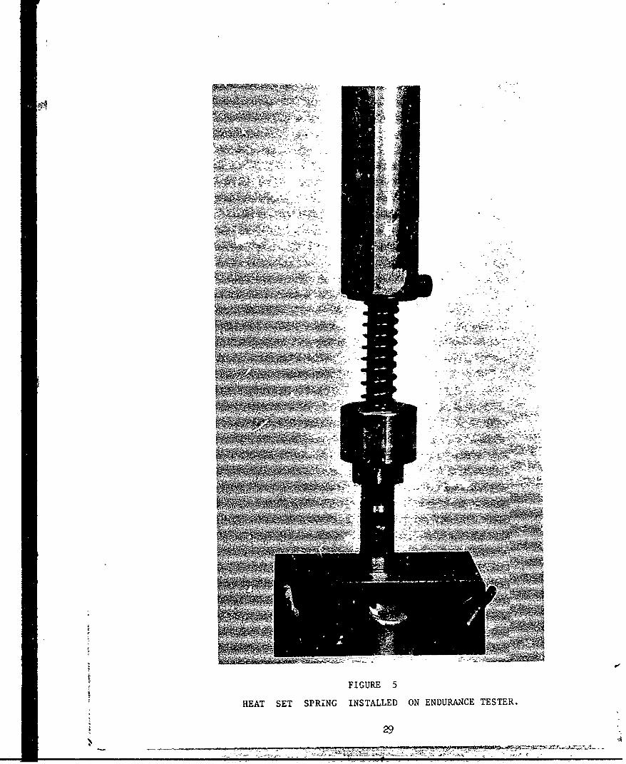
Test fixtures *.ere designed end fabricated to endurance test thesprings on the Krouse spring tester. A photograph of a heat set springassembled onto the tester is shown Ln Figure 5 in the Appendix. Someexperimentation in the enturance testing was necessary in order toestablish the proper test conditions for the working stress levelsand cynlic frequency which would produce spring set with the minimunamount of sprirg breakage. It was determined that the music wire springsshould be cycled between the heights of 2.500 and 1.000 inchee whichcorresponds to stress levels of 18,000 psi and 152,000 psi respectively;and at a frequency of 1275 cycles per minute. Springs were cycled fora total of 50,000 compressions with measurements taken of the freeheights and spring loads periodically during the test.
Load at 2.500 iaches and free height measurements taken on theindividual music w- re springs before and after 50,000 compressioncycles are shown in tables 1 to 6 in the Appendix. Test results of onlyfour springs are given for set 1 because six springs from this set wereexpended to establish the stress and frequency test conditions. Fewerthan 10 springs are also listed in some of the other sets, due to springbreakage that occurred before the completion of 50,000 cycles.
The stainless steel springs were endurance tested between thehe-.ghts of 2.200 and 1.000 inches which cormesponds to stress levels of41,000 psi and 139,000 psi respectively; and at a rate of 1000 cycles
per minute. Three springs each from sets 2 and 6 were used to establishthe test conditions. Measured free height and load measurements takenon the springs before and after cycling are shown in tables 7 to 12.Five springs each from sets 9 and 10 were tested since this samplewas considered sufficient to provide adequate data to assess springcharucteristics.
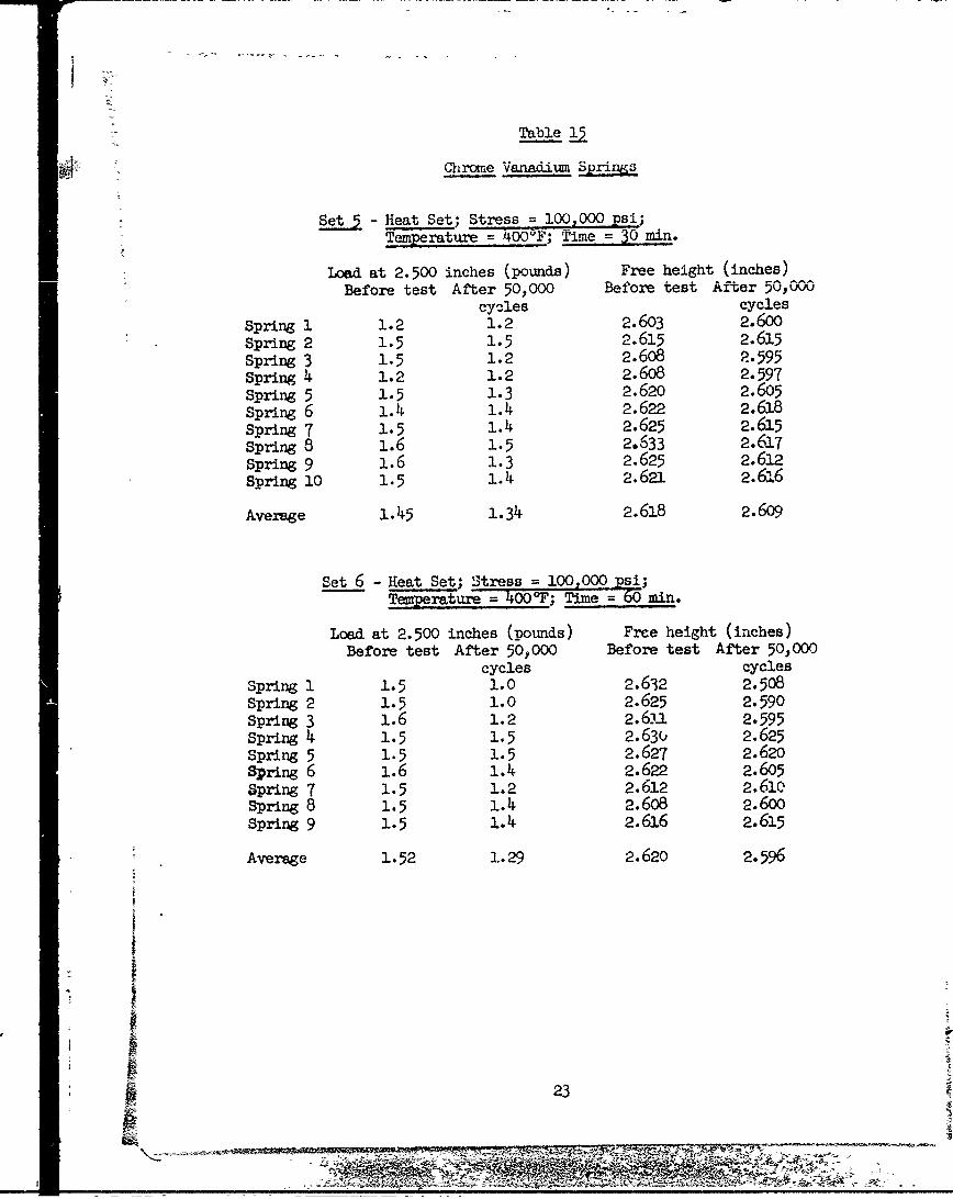
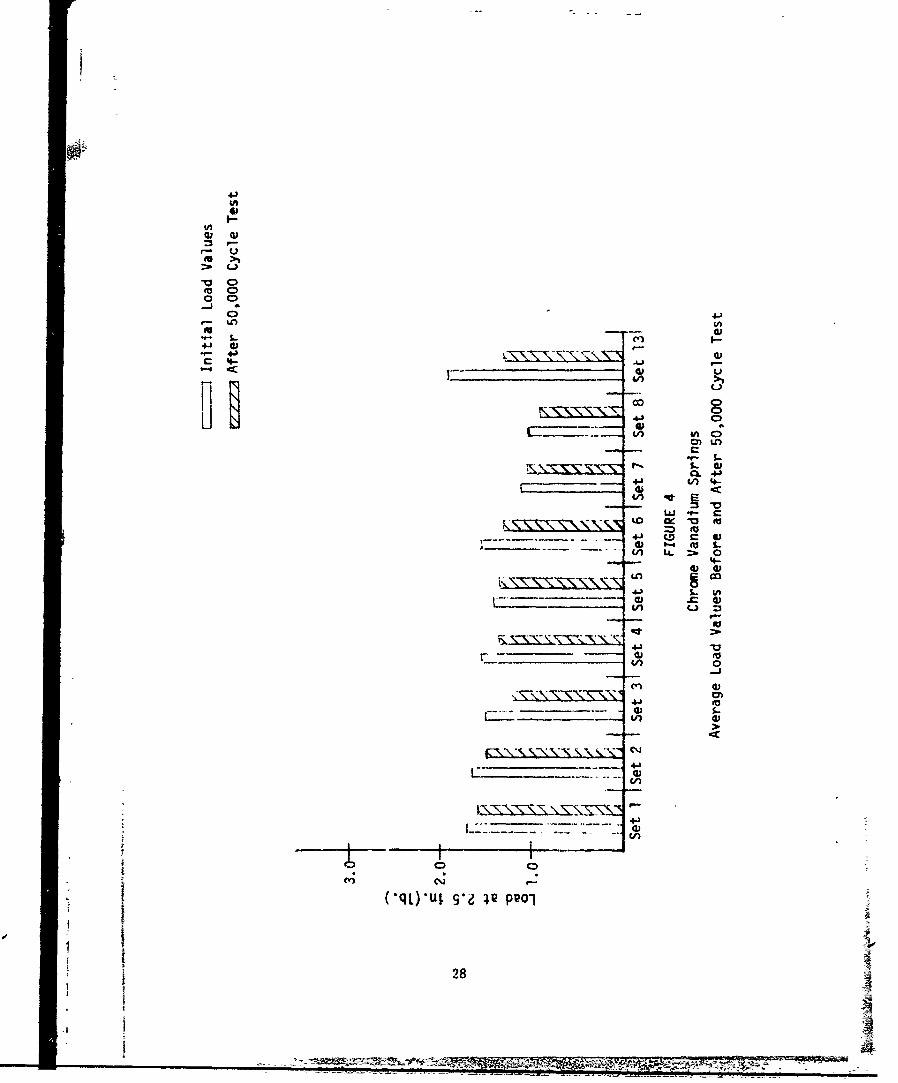
The chrome vanadium springs were endurance tested under the same con-ditiona as weri the music wire springs. Test data for the chrome vat.-adjure springs are given iii tables 13 to 17.
The criteria used in measuring the amount Of spring set are theload at a particular compressed height and the change in free height.The spring load (at 2.500 inches) is considered a more practical andmeaningful method to measure set for this project. Some of the heat
3
- -~ .77~~5F77 7 -t %z
*~7 - 7pa-wt- W&ý
setting procedures that were used proved to be too severe for the springmaterial and produced an excessive set. In s(ne cases, the resultantfree height after the heat setting operation was less than 2.500 inches;this occurred with the heat setting procedures that were performed ata stress level of 150,000 psi and at the maximum temperature. Ex-cessive set as a result of the heat setting treatment occurred to sets11 and 12 of the music wire and stainless steel springs as well as tosets 9 to 12 of the chrome vanaditin springs. Consequently, these setswere not endurance tested because the free heights were slightly aboveor below the 2.500 value.
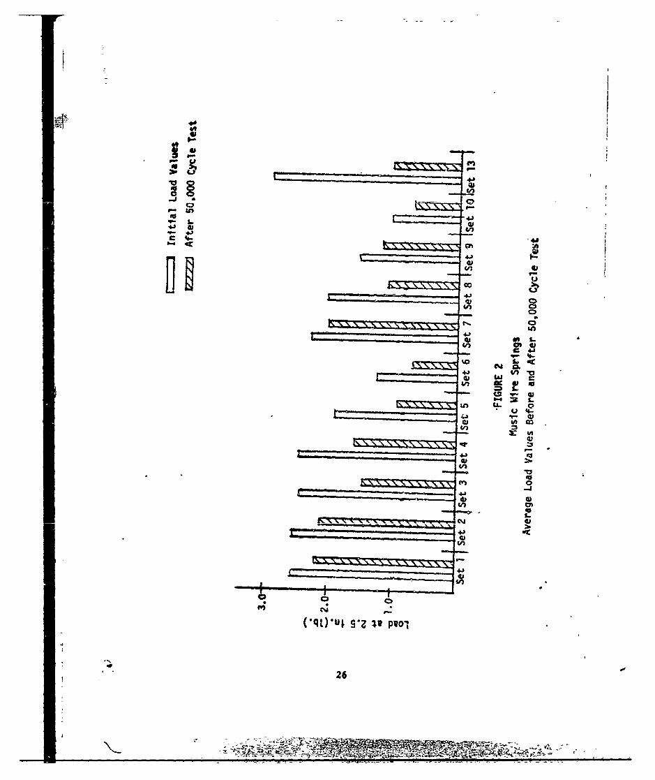
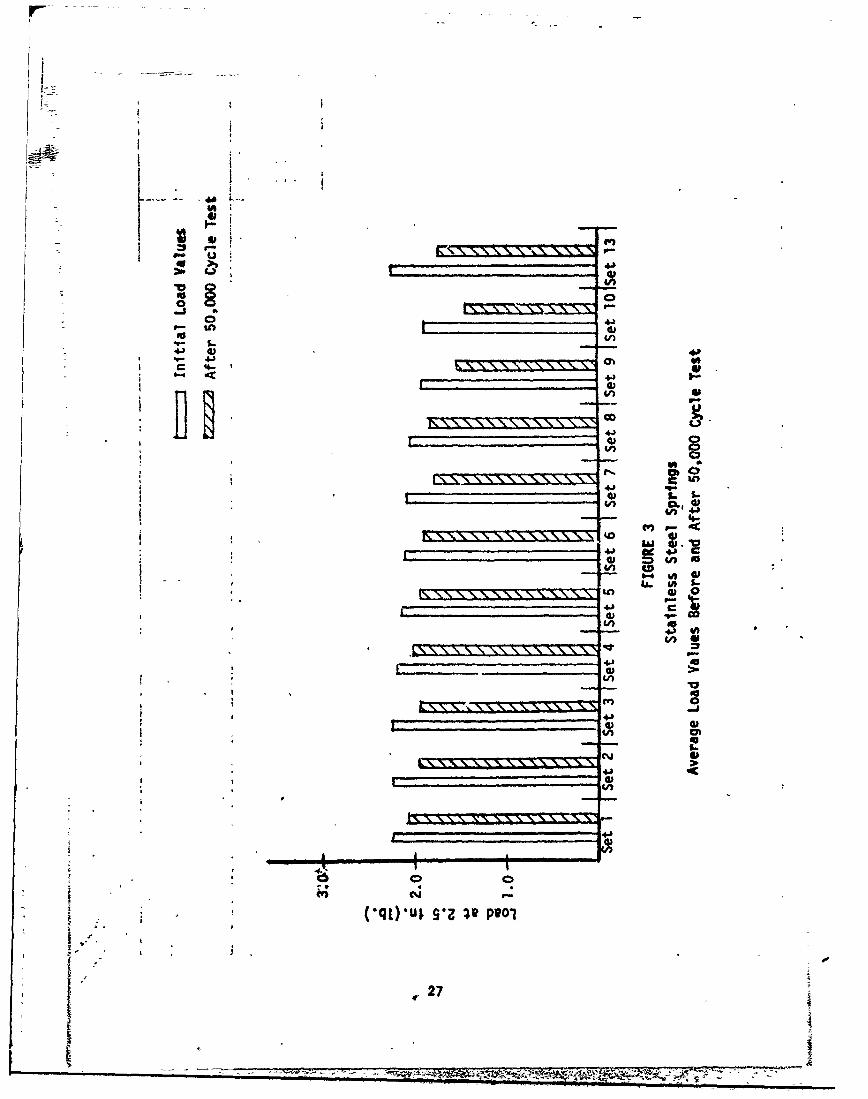
The average load values before and after 50,000 cycles of each setof music wire springs are shown in figure 2 in the Appendix. For eachset, the left bar column represents the average load before the endur-ance test and the right bar coltmn indicates the average value after the50,000 compressions. Similarly, the average load values for the stain-less steel and chrome vanadiim spring sets are depicted in figures 3and 4 respectively.
CONCLLUIONS
A review of figure 2 shows that the heat setting procediute that ismost effective for music wire springs to minLaize load loss due tooperational set is the procedure that was applied to set 1 (i.e. stresslevel = 100,000 psi, temperature = 200OF and time = 30 minutes.) Thefinal load after testing for set 1 is twice as large as the final loadfor the untreated set 13. The heat setting procedures that were givento sets 2 and 7 were almost equally beneficial since these springssustained a high load level.
Figure 3 shows that all the heat setting treatments that were per-formed at a stress level of 100,000 psi aided to increase the durabilityof the stainless steel springs. However, the treatments that were appliedto sets 1. and 4 provided the best results.
The benefit derived from heat setting by the chrome vanadiumsprings is rather minimal as naa be observed from figure 4. The heatsetting procedure that is related to set 1 induced the most favorablestrength properties.
Load retention property of music wire springs is benefitted moreby heat setting than those of stainless steel or chrome vanadium springs.
Generally, the difference in heating times of 30 minutes and 60minutes had little effect on spring :oad dxrability.
Test results shorw that of the three temperature values that wereused in this study, the t -mperature of 2000F produced the most favorableresults. However, it is possible that a somewhat ltwer temperature mayproduce an even higher re,-istance to sprin• set. Li;qitations on fundsand material precluded the evaluation of other temperature variables.
4
~1;N
RECOMIUENDATIONS
I. The heat setting procedure if
Stress level = 1•0,000 psiTemperature = 200OFTime at temperatur,' = 30 minutes
should be applied to the following materials and operating conditions:
Music wire and chrome vanadium materialsWire size approximately .043 inchStress range of 18,0OC psi to 152,000 psiLoading frequency 1275 cycles per minute
Stainless steel materialWire size approximatelz .043Stress range 41,000 psi to 13",000 psiLoadirg frequency 100C cycles per minute
2. Temperatures in the ra ige of 100OF to 200OF should be investigatedif a further study on ieat setting procedure is conducted.
5
Appendix
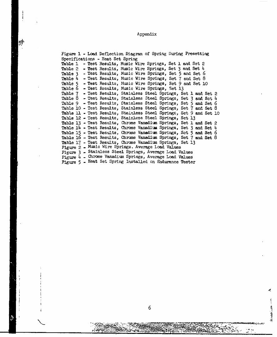
Figure 1 - Load Deflection Diagram of Spring During PresettingSpecifications - Heat Set SpringTable 1 - Test Results, Music Wire Springs, Set 1 and Set 2Table 2 - Test Results, Music Wire Springs, Set 3 and Set 4Table 3 - Test Results, Music Wire Springs, Set 5 and Set 6Table 4 - Test Results, Music Wire Springs, Set 7 and Set 8Table 5 - Test Results, Music Wire Springs, Set 9 and Set 10Table 6 - Test Results, Music Wire Springs, Set 13Table 7 - Test Results, Stainless Steel Springs, Set 1 and Set 2Table 8 - Test Results, Stainless Steel Springs, Set 3 and Set 4Table 9 - Test Results, Stainless Steel Springs, Set 5 and Set 6Table 10 - Test Results, Stainless Steel Springs, Set 7 and Set 8Table U1 - Test Results, Stainless Steel Springs, Set 9 and Set 10Table 12 - Test Results, Stainless Steel Springs, Set 13Table 13 - Test Results, Chrome Vanadium Springs, Set 1 and Set 2Table 14 - Test Results, Chrome Vanadimu Springs, Set 3 and Set 4Table 15 - Test Results, Chrome Vanadium Springs, Set 5 and Set 6Table 16 - Test Results, Chrome Vanadium Springs, Set 7 and Set 8Table 17 - Test Results, Chrome Vanadium Springs, Set 13Figure 2 - Music Wire Springs, Average Load ValuesFigure 3 - Stainless Steel Springs, Average Load ValuesFigure 4 - Chrome Vanadium Springs, Average Load ValuesFigure 5 - Heat Set Spring Installed on Endurance Tester
6

*hC
4J,
CC
4.,
44,
4J
10
d, 66;Cs op

SPECIFICATIONS
HEAT SET SPRING
WIRE SIZE (IN.) .043
OUTSIDE DIAMETER (IN.) .370±. 005
TO0TAL COILS 18.5
TYPE OF END6 CLOSED AND GROUND
FREE HEIGHT, APPROX. (IN.) 2.70MEAN ASSEBLEM D HEIGHT (IN.) 2.500
LOAD AT MEAN ASS&IBLED HEIGHT (LB.) 2.0 REF.
MINIMUM OPERATION HEIGHT (IN.) 1. 000
LOAD-DEFLECTION RATE (LB./IN.) 8.5
MAX.. 'UM SOLID HEIGHT (IN.) .830
SPRING HELIX L.H.
8ý - l
ýt
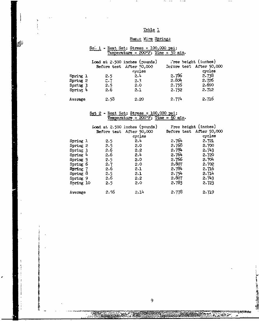
¶Tble 1
Music Wire Springa
Se. I -Heat Set; Stress = .00,000 psi;TTemerature = 200oF; Time = .30 m.
Load at 2.500 inches (pounds) i'ree height (inches)Before test After 50,000) 3cifore test After 50,000
rcycles cycles$pring 1 2.5 2.4 2.786 2.738Spring 2 C.7 2.3 2.804 2.726Sprý.ng 3 2.5 2M0 2.756 2.690Spring 4 2.6 2.1 2.752 2.712
Average 2.53 2.20 2.774 2.716
Set 2 - Heat Set; Stress =-0 0 k;Temperature = 200IF; Time =60 min.
Load at 2.500 inches (pounds) Free height (inches)Before test After 50,000 Before test After 50,000
cycles cyclesSpring 1 2.5 2.4 2.764 2.721Spring 2 2.5 2.0 2.768 2.700Spring 3 2.6 2.2 2.784 2.743Spring 4 2.6 2.4 2.764 2.720Spring 5 2.5 2.0 2.766 2.704Spring 6 2.7 2.0 2.807 2.702Spring 7 2.6 2.1 2.784 2.716Spring 8 2.5 2.1 2.754 2.714Spring 9 2.6 2.2 2.807 2.743Spring 10 2.5 2.0 2.783 2.723
Average 2.56 2..4 2.778 2.719
9
2 -0 7i~

Table 2
OF Music Wire arigge
Se H -eat Set; Stress 190,.000 psi;Tempatur Tim = .200 in
Load at 2.500 i.ches (pounds) Free height (inches)Before test ,fter 50,,C'0 Before test After 50,000cycles c:yc:lesSpring 1 2.5 1.2 2.743 2.6o4Spring 2 2.4 1.0 2.753 2.606Spring 3 2.6 2.0 2.804 2.706Spring 4 2.3 2.0 2.764 2.708Spring 5 2.4 1.4 2.753 2.652Spring 6 2.5 1.7 2.764 2.703Spring 7 2.6 1.3 2.804 2.609Ppring 8 2.4 0.9 2.766 2.546
Average 2.46 1..44 2.769 2.642
Set 4 - Heat Set; Stress =1I00 000 sj ;Temperature = 30 0F; ime = 60 min.Load at 2.500 inches (pounds) Free height (inches)Before test After 50,000 Before test After 50,000
cycles cyclesSpring 1 2.4 1.5 2.758 2,66:zSpring 2 2.5 1.6 2.749cSpring 3 2.5 1.5 2.766 2 653Spring 4 2.3 1.17 2.743 2.653Spring 5 2.5 1.2 2.767 2.65-Spring 6 2.4 1.7 2.746 2.684Spring 7 2.5 2.0 2.748 2.705Spring 8 2.5 1.6 2.744 2.709Average 2.45 1.60 2.753 2.682
10
R-."mv
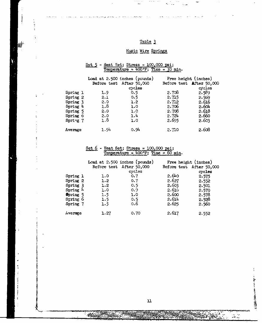
•i. Table
Music Wire Springs
Set 5 - ieat Set; Stress = 100,000 psi;Ti u 4o00 0 F; Time = 30 mi.
Load at 2.500 inches (pounds) Free height (inches)Before test After 50,000 Before test After 50,000
cycles cyclesSpring 1 1.9 0.5 2.708 2.589Spring 2 2.1 0.5 2.715 2.569spring 3 2.0 1.2 2.712 2.616Spring 4 1.8 1.0 2.7o6 2.6o4Spring 5 2.0 1.0 2.708 2.618Spring 6 2.0 1.4 2.724 2.660Spring 7 1.8 1.0 2.695 2.603
Average 1.94 o.94 2.710 2.608
Set 6 - Heat Set; Stress = 100,000 psi;Temperature' =OOF; Time = 60 amin.
Lead at 2.500 inches (pounds) Free height (inches)Before test After 50,000 Before test After 50,000
cycles cyclesSpring 1 1.0 0.7 2.6LO 2.575Spring 2 1.2 0.7 2.627 2.552Spring 3 1.2 0.5 2.603 2.501Spring It 1.0 0.9 2.610 2.570Spidng 5 1.5 1.0 2.6oo 2.578String 6 1.5 0.5 2.614 2.528Spring 7 1.5 o.6 2.625 2.560
Average 1.27 0.70 2.617 2.552
P
I
II
AR g
-c MIý
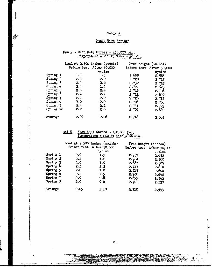
Table 4
Muzic Wire S
et 7 - Heat Set, Stress = 150,000 psi;Temrature = 2000F; Time = 30 min.
Ioead at 2.500 inches (poundd) Free height (inches)Before test After 50,000 Before test After 50,000
cycles cyclesSpring 1 1.7 1.5 2.695 2.565Spring 2 2.4 2.2 2,720 2.715Spring 3 2.4 2.2 2.732 2.725Spring 4 2.4 1.5 2.727 2.625spring 5 2.4 2.4 2.716 2.708spring 6 2.4 2.2 2.712 2.690SrPig ' 2.4 2.2 2,728 2.717Spring 8 2,2 2.2 2.706 2.706Spring 9 2.4 2.2 2.741 2.723Spring 10 2.2 2.0 2.7-02 2.680
Average 2.29 2.06 2.-'18 2.685
set 8 - Heat Sets Stress 150,000 psi;
Temperature = 2000F; Time = 6o min.
Load at 2.500 inches (pounds) Free height (inches)Before test After 50,000 Before test After 50,000
cycles cyclesSprlng 1 2.0 1,5 2.757 2.652Spring 2 2.1 1. 2 2.704 2.580Spring 3 2.0 1.0 2.687 2.585Spring 4 2.Z 1.2 2.713 2.610Spring 5 2.0 1.0 2.7-15 2.600Spring 6 2.1 1.5 2.708 2.64o0spring 7 2.0 o.8 2.695 2.542Spring 8 2.0 0.6 2.701 2.538
Average 2.05 1.10 2.710 2.593
12
"R n9
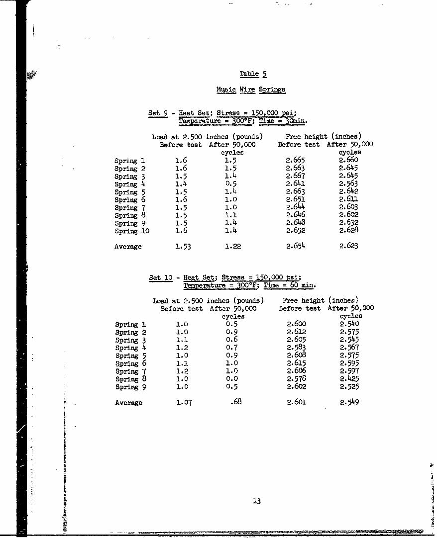
Table 2
Music Wire Springs
Set 9 - Heat Set; Stress = 150,000 psi;Tempexvture =300 0F; Tie=3mn
Load at 2.500 inches (pounds) Free height (inches)Before test After 50,000 Before test After 50,000
cycles cyclesSpring 1 1.6 1.5 2.665 2.660Spring 2 1.6 1.5 2.663 2.645Spring 3 1.5 1.4 2.667 2.645spring 4 1.4 0.5 2.641 2.563Spring 5 1.5 1.4 2.663 2.642Spring 6 1.6 1.0 2.651 2.611Spring 7 1.5 1.0 2.644 2.603Spring 8 1.5 1.1 2.646 2.602Spring 9 1.5 1.4 2.648 2.632Spring 10 1.6 1.4 2.652 2.628
Average 1.53 1.22 2.654 2.623
Set 10 - Heat Set; Stress = 150,000 psi;-Tepemiture = 300*F; Time = 60 min.
Load at 2.500 inches (pounds) Free height (inchez)Before test After 50,000 Before test After 50,000
cycles cyclesSpring . 1.0 0.5 2.6oo 2.54oSpring 2 1.0 0.9 2.612 2.575Spring 3 ,..1 o.6 2.605 2.545Spring 4 1.2 0.7 2.583 2.567Spring 5 1.0 0.9 2.608 2.575Spring 6 1.1 1.0 2.615 2.595Spring 7 1.2 1.0 2.606 2.597Spring 8 1.0 0.0 2.578 2.425Spring 9 1.0 0.5 2.6o2 2.525
Average 1.07 .68 2.601 2.549
2
13
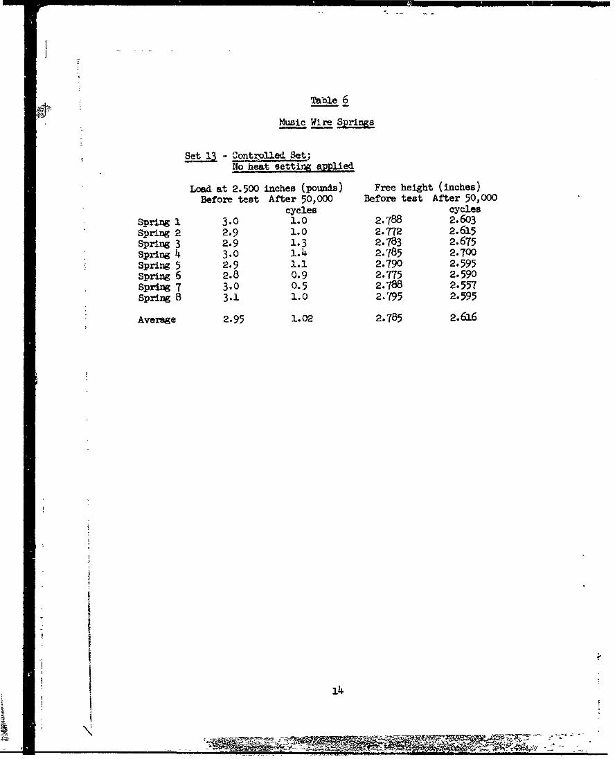
Table 6
Music Wire S
Set_ 1 - contr Set;No heat setting applied
Load at 2.500 inches (pounds) Free height (inches)Before test After 50,000 Before test After 50,000
cycles cyclesSpring 1 3.0 1.0 2.788 2.6o3Spring 2 2.9 1.0 2.772 2.615Spring 3 2.9 1.3 2.783 2.675spring 4 3.0 1.4 2.785 2.700Spring 5 2.9 1.1 2.790 2.595Spring 6 2.8 0.9 2.775 2.590Spring 7 3.0 0.5 2.788 2.557Spring 8 3.1 1.0 2.795 2.595
Average 2.95 1.02 2.785 2.616
I
, !,
14
_ 2R!ý

Table 1
Stainless Steel sPrings
Set 1 - Heat Set; Stress 100,000 psi;Temperinture~ F Ti00Eýme-= 30 min.
Load at 2.500 inches (pounds) Free height (inches)Before test After 50,000 Before test After 50,000
cycles cyclesSpring 1 2.2 2.2 2.740 2.720Spring 2 2.3 2.2 2.745 2.740sprirz 3 2.2 2.2 2.750 2.735Spring 4 2.5 2.2 2.745 2.740spring 5 2.2 2.0 2.730 2.715Spring 6 2.2 1.7 2.740 2.655Spring 7 2.3 2.2 2.755 2.737Sprirg 8 2.2 2.0 2.755 2.645
Average 2.26 2.09 2.745 2.7.1
Set 2 - Heat Set; Stress = 100,000 psi;Temperature = 200 F; Time 60 min.
Load at 2.500 inches (poumds) Free height (inches)Before test After 50,000 Before test After 50,000
cycles cyclesSpring 1 2.2 1.8 2.775 2.640Spring 2 2.2 2.0 2.735 2.725Spring 3 2.3 2.0 2.745 2.720Spring 4 2.2 2.0 2.740 2.723Spring 5 2.4 2.1 2.747 2.688Spring 6 2.4 2.0 2.737 2.725Spring 7 2.2 1.9 2.725 2.693
Average 2.27 1.97 2.743 2.702
I
IS
i
I
15
~ 4 ~~4~> ~ - - - ~4-g rlnvz4 ý -
7~3T
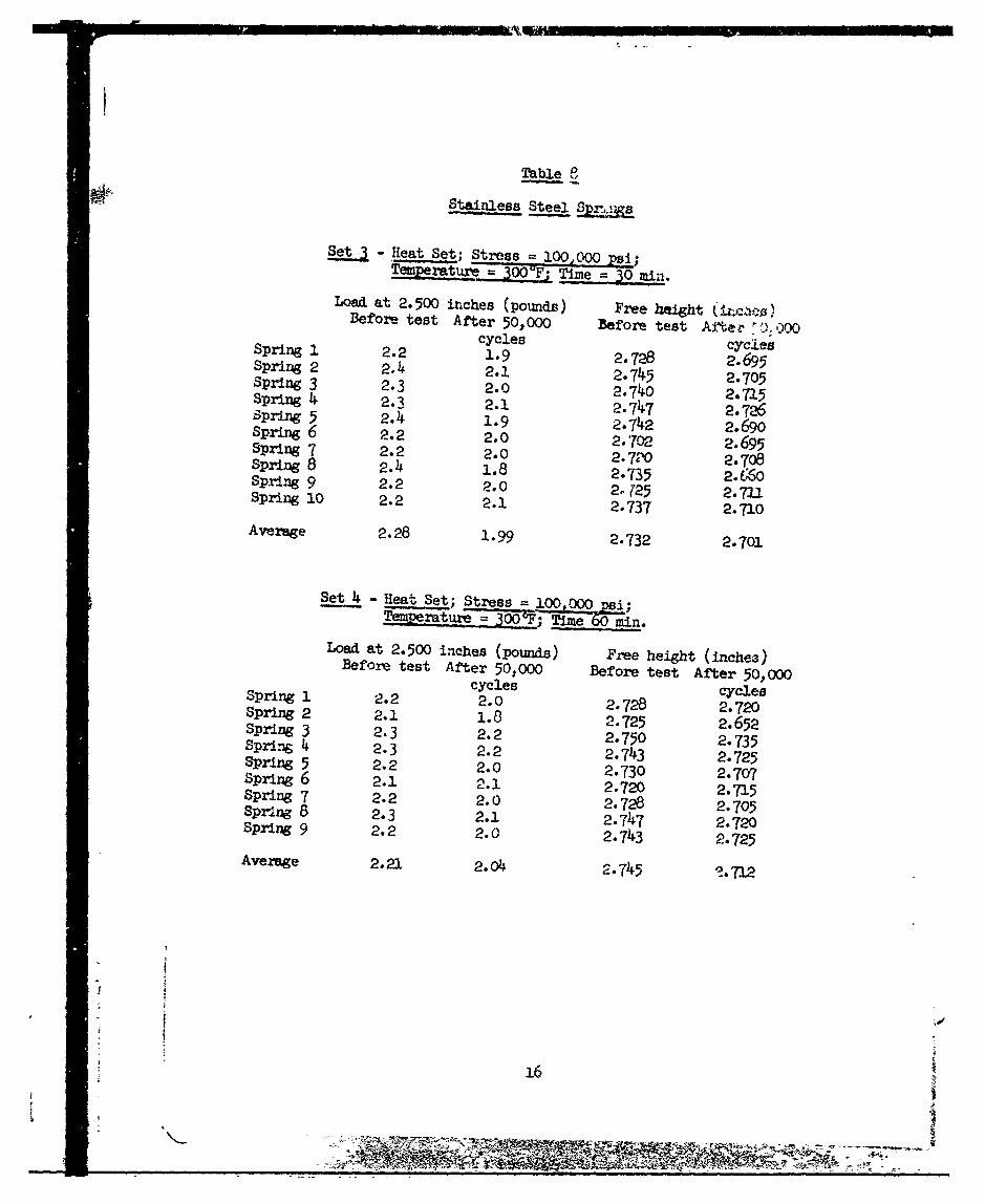
Table 8
Stainless Steel
Set 3- Heat Set; Stress = 100,000 psi;Tempeture = 300:F T!me = 30,.m-
Load, at 2.500 inches (pounds) Free height (i.s)Before test After 50,000 Before test After [).000cycles cyc.LesSpring 1 2.2 1.9 2.728 2.695Spring 2 2.4 2.1 2.745 2.705spring 3 2.3 2.0 2.740 2.715Spring 4 2.3 2.1 2.747 2.7q6Spring 5 2.4 1.9 2.742 2.690spring 6 2.2 2.0 2.702 2.695Spring 7 2.2 2.0 2.74"0 2.708Spring 8 2.4 1.8 2.735 2.660Spring 9 2.2 2.0 2.T25 2.711Spring 10 2.2 2.1 2.737 2.710
Average 2.28 1.99 2.732 2.701
Set 4 -Heat Set; Stress 100 000 ".i;Tpemerature = 3005'F; Time O Rmn.
Load at 2.500 inches (pounds) Free height (inches)Before test After 50,000 Before test After 50,000cycles cyclesSpring 1 2.2 2.0 2.728 2.720Spring 2 2.1 1.8 2.725 2.652Spring 3 2.3 2.2 2.750 2.735sprin. 4 2.3 2.2 2.743 2.725Spring 5 2.2 2.0 2.730 2.707Spring 6 2.1 2.1 2.720 2.715Spring 7 2.2 2.0 2.728 2.705Spring 8 2.3 2.1 2.747 2.720Spring 9 2.2 2.0 2.743 2.725
Average 2.21 2.04 2.745 -. 712
16
047 -i -x -MR It -t
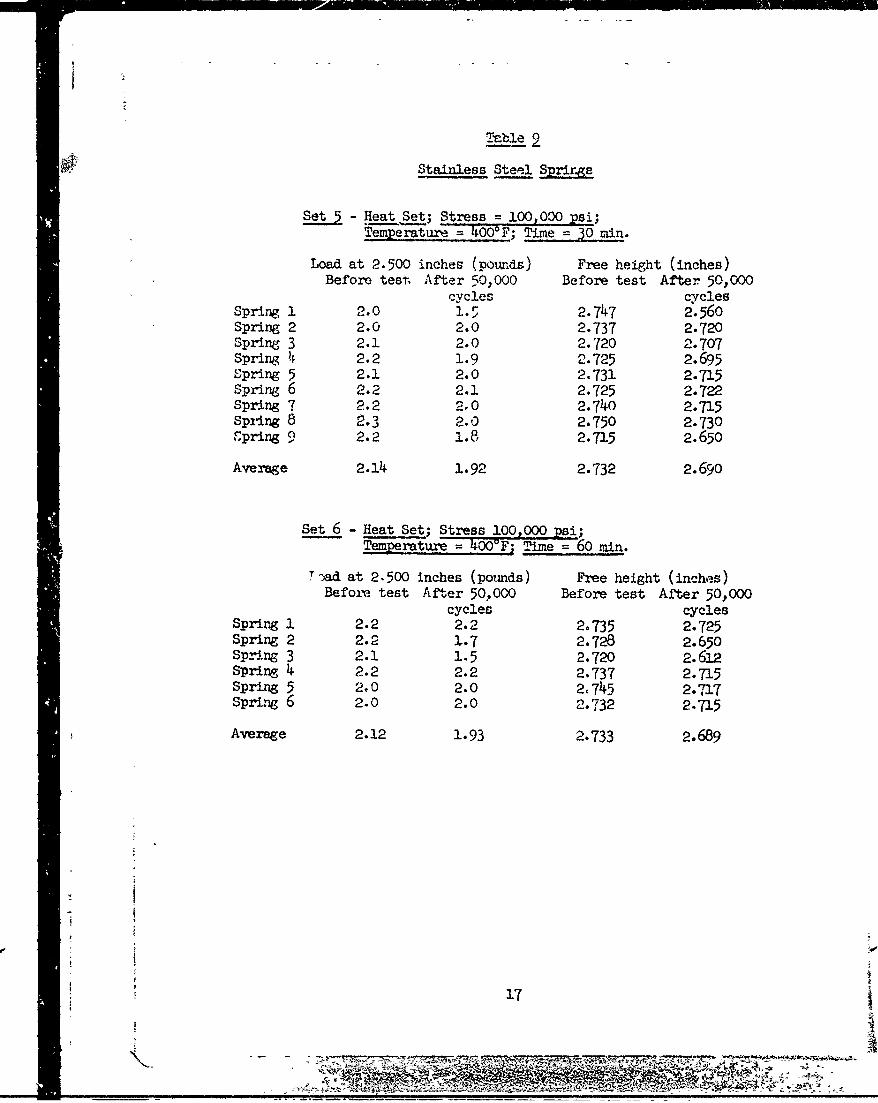
Tezble 2Stainless Steel Prir&ge
Set 5- Heat Set; Stress = 100,000 psi;Temperature -= 400OF; Time = O min.
Load at 2.500 inches (pomuds) Free height (inches)Before test, After 50,000 Before test After 50,000
cycles cyclesSpring 1 2.0 1.5 2.747 2.56oSpring 2 2.0 2.0 2.737 2.720Spring 3 2.1 2.0 2.720 2.707Spring 4 2.2 1.9 2.725 2.695Spring 5 2.1 2.0 2.731 2.715Spring 6 2.2 2.1 2.725 2.722Spring 7 2.2 2.0 2.740 2.715Spring 8 2.3 2.0 2.750 2.730spring 9 2.2 1.8 2.715 2.650
Average 2.14 1.92 2.732 2.690
Set 6 - Heat Set; Stress 100,000 psi;-- Tmperture = 400'F- M"me - 40 rain.
T -ad at 2.500 inches (poumds) Free height (inches)Before. test After 50.000 Before test After 50,000
cycles cyclesSpring 1 2.2 2.2 2.735 2.725Spring 2 2.2 1.7 2.728 2.650Spring 3 2.1 1.5 2.720 2.612Spring 4 2.2 2.2 2.737 2.715Spring 5 2.0 2.0 2,745 2.717Spring 6 2.0 2.0 2.732 2.715
Average 2.12 1.93 2,733 2.689
- !÷
17
,-5,
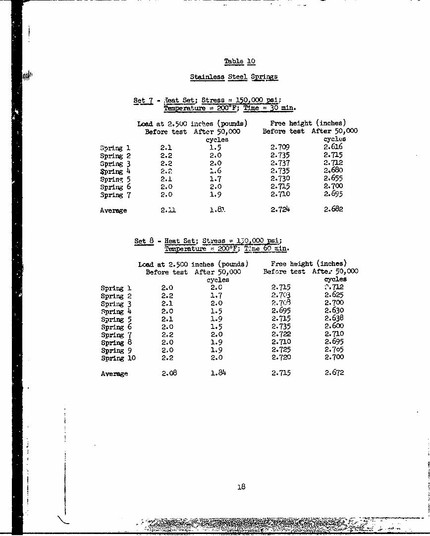
Table 10
Stainless Steel Sprn
Set. - jeat Set; Stress .-- 150,000 Lsi..Tenmerature = ý F; m = 50 mrin.
Load at 2.500 inches (pounds) Free height (inches)Before test After 50,000 Before test After 50,000
cycles cyclesSpring 1 2.1 1.5 2.709 2.616Spring 2 2.2 2.0 2.735 2.715spring 3 2.2 2.0 2.737 2.712spring 4 2.2 ,.6 2.735 2,68oSpring 5 2.1 1.7 2.730 2.655Spring 6 2.0 2.0 2.715 2.700Spring 7 2.0 1.9 2.710 2.695
Average 2. i1 1.87- 2.724 2.682
Set 8 - Heat Set; Stress 1=710 0Pi;Tmm'aure :--200°F; Time zO =in.
Load at 2.500 inches (pounds) Free height (inches)Before test After 50,000 Before test Afte." 50,000
cycles cyclesSpring 1 2.0 2.0 2.715 V.712Spring 2 2.2 1.7 2.7C3 2.625Spring 3 2.1 2.0 P-.7•3 2.700Spring 4 2.0 1.5 2.695 2.630
Spring 5 2.1 1.9 2.715 2.638Spring 6 2.0 1.5 2.735 2.600spring 7 2.2 2.0 2.722 2.710Spring 8 2.0 1.9 2.710 2.695Spring 9 2.0 1.9 2.725 2.705Spring 10 2.2 2.0 2.720 2.700
Average 2.08 1.84 2.715 2.672
18
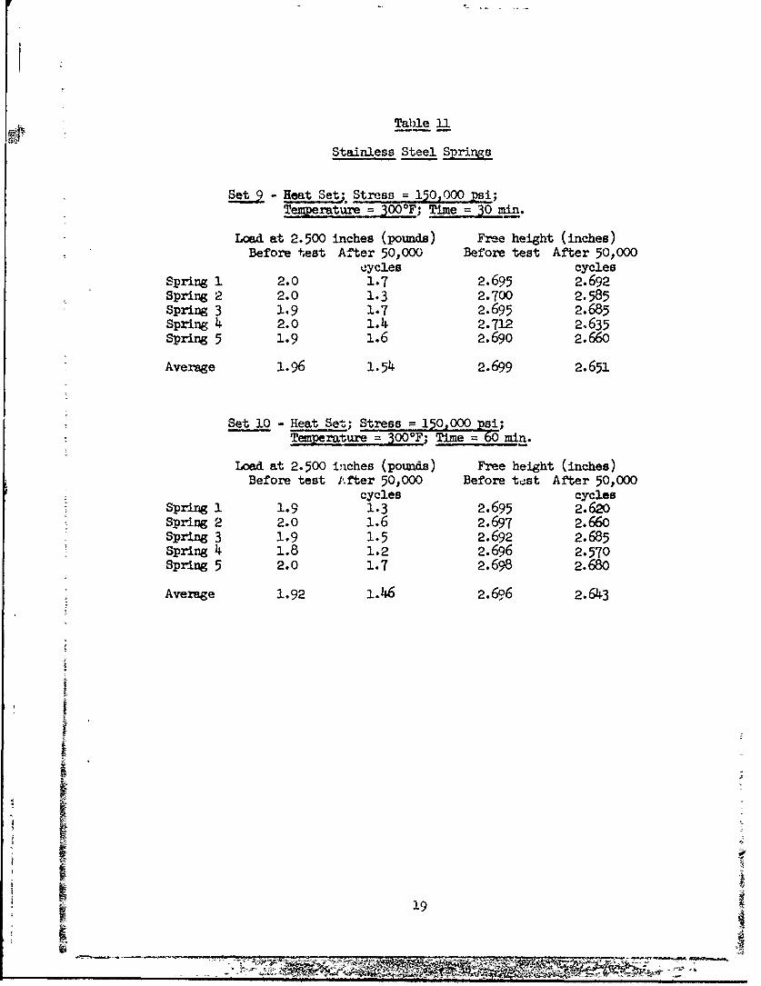
Table 11
Stainless Steel Springs
Set 9 Heat Set; Stress = 150,000 psi;Temperature = 300°F; Time = 30 mn.
Load at 2.500 inches (pounds) Free height (inches)Before test After 50,000 Before test After 50,000
cycles cyclesSpring 1 2.0 1.7 2.695 2.692Spring 2 2.0 1.3 2.700 2.585Spring 3 1.9 1.7 2.695 2.685Spring 4 2.o 1.4 2.712 2.635Spring 5 1.9 1.6 2.690 2.660
Average 1.96 1.54 2.699 2.651
Set 10 - Heat Set; Stress = 150,000 psi;- Tqemratue = 300°F; Time = 60 'm.
Load at 2.500 inches (pounds) Free height (inches)Before test After 50,000 Before test After 50,000
cycles cyclesSpring 1 1.9 1.3 2.695 2.620Spring 2 2.0 1.6 2.697 2.660Spring 3 1.9 1.5 2.692 2.685Spring 4 1.8 1.2 2.696 2.570Spring 5 2.0 1.7 2.698 2.680
Average 1.92 1.146 2.696 2.643
SI I19
_ _ _ _ _ _ _ _ _ _
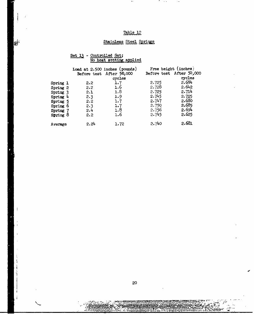
Table 12
Stainless Steel Springs
Set 13 - Controlled Set;No heat setting applied
Load at 2.500 inches (pounds) Free height (inches)Before test After 50,000 Before. test After 50.,000
cycles cycles
Spring 1 2.2 1.7 2.725 2.684Spring 2 2.2 1.6 2.728 2.642spring 3 2.1 1.8 2.725 2.714Spring 4 2.3 1.9 2.745 2.725Spring 5 2.2 1.7 2.747 2.680Spring 6 2.3 1.7 2.750 2.685Spring 7 2.4 1.8 2.756 2.694spring 8 2.2 1.6 2.745 2.625
Average 2.24 1.72 2.(40 2.681
i-
20
....... . . . . . .
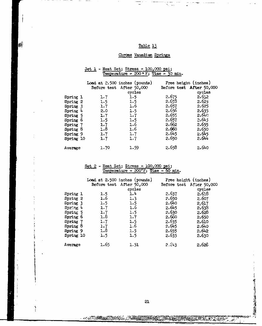
Table 13
Chrome Vanadium Springs
Oeti - Heat Set; Stress = 100,000 psi;Temperature = 200'* F; Time = 30 min.
Load at 2.500 inches (pounds) Free height (inches)Before test After 50,000 Before test After 50,000
cycles cyclesSpring 1 1.7 1.5 2.675 2.632Spring 2 1.5 1.5 2.658 2.625Spring 3 1.7 1.6 2.657 2.625Spring 4 2.0 1.5 2.656 2.635Spring 5 1.7 1.7 2.655 2.64oSpring 6 1.5 1.5 2.657 2.645Spring 7 1.7 1.6 2.662 2.655Spring 8 1.8 1.6 2.66o 2.650Spring 9 1.7 1.7 2.645 2.645Spring 10 1.7 1.7 2.650 2.644
Average 1.70 1.59 2.658 2.640
Set 2 - Heat Set; Stress 100,000 psisTemperature = 2000 F; Time = 60 min.
Load at 2.500 inches (pounds) Free height (inches)Before test After 50,000 Before test Af!2er 50,000
cycles cyclesSpring 1 1.5 1.4 2.637 2.618Spring 2 1.6 1.3 2.650 2.607Spring 3 1.5 1.5 2.640 2:617Sp•r g 4 1.7 1.6 2.645 2.638Spring 5 1.7 1.5 2.630 2.628Spring 6 1.8 1.7 2.660 2.650spring 7 1.7 1.5 2.635 2.61oSpring 8 1.7 1.6 2.645 2.64oSpring 9 1.8 1.5 2.655 2.642Spring 10 1.5 1.5 2.635 2.630
Average 1.65 1.51 2-643 2.628
213.
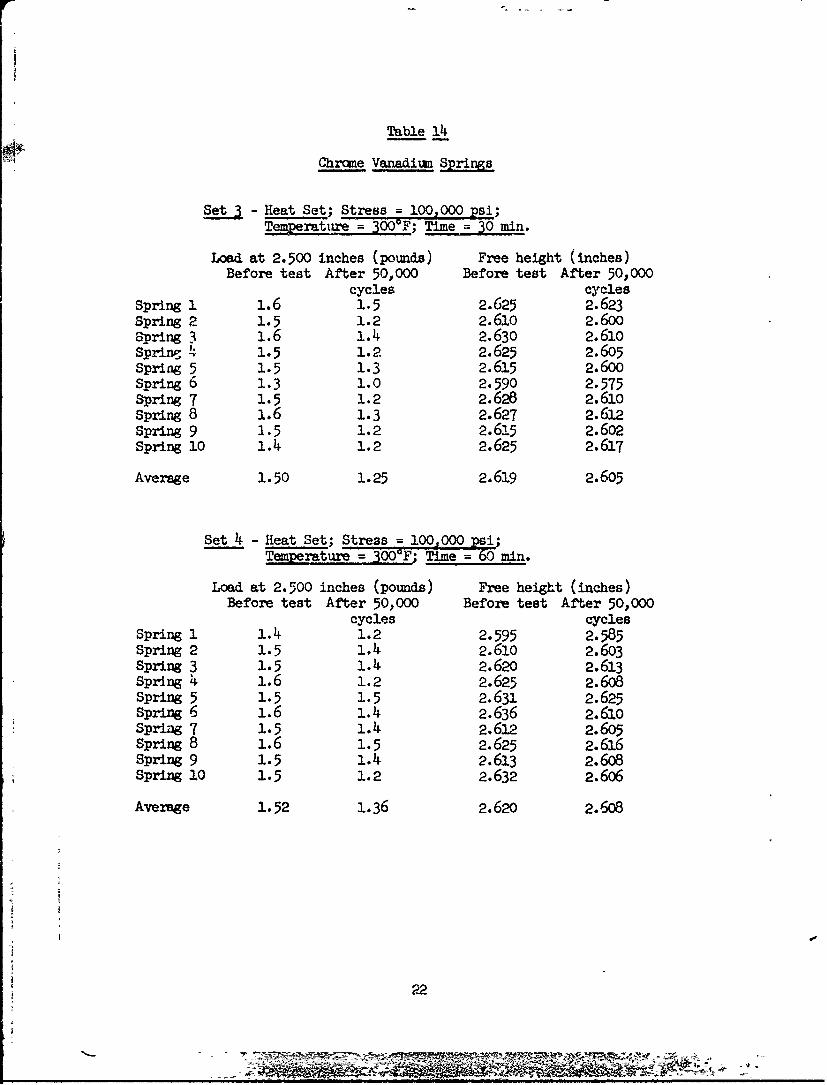
Table 14
Chrome Vanadium S
S 3- Heat Set; Stress = 100,000 psi;Tepjrjture = 300°F; Time = 30 mn.
Load at 2.500 inches (pounds) Free height (inches)Before test After 50,000 Before test After 50,000
cycles cyclesSpring 1 1.6 1.5 2.625 2.623Spring 2 1.5 1.2 2.610 2.600Spring 3 1.6 1.4 2.630 2.61oSpring . 1.5 1.2 2.625 2.605Spring 5 1.5 1.3 2.615 2.600Spring b 1.3 1.0 2.590 2.575Spring 7 1.5 1.2 2.628 2.610Spring 8 1.6 1.3 2.627 2.612Spring 9 1.5 1.2 2.615 2.602Spring 10 1.4 1.2 2.625 2.617
Average 1.50 1.25 2.619 2.605
Set 4 - Heat Set; Stress = 100,000 psi;TemperauE = 3 F Time NO6 min.
Load at 2.500 inches (pounds) Free height (inches)Before test After 50,000 Before test After 50,000
cycles cyclesSpring 1 1.4 1.2 2.595 2.585Spring 2 1.5 1.4 2.61o 2.6o3Spring 3 1.5 1.4 2.62o 2.613spring 4 1.6 1.2 2.625 2.6o8Spring 5 1.5 1.5 2.631 2.625Spring 6 1.6 1.4 2.636 2.61oSpriag 7 1.5 1.4 2.612 2.605Spring 8 1.6 1.5 2.625 2.616Spring 9 1.5 1.4 2.613 2.608Spring 10 1.5 1.2 2.632 2.6o6
Average 1.52 1.36 2.62o 2.608
22
-- ---71
Table
Chrome Vanadium Springs
- Heat Set; Stress = 100,000 psi;Temperature = 400F; Time = 30 rin.
Load at 2.500 inches (pounds) Free height (inches)Before test After 50,000 Before test After 50,000
cycles cycles
Spring 1 1.2 1.2 2.6o3 2.6ooSpring 2 1.5 1.5 2.615 2.615
Spring 3 1.5 1.2 2.608 2.595Spring 4 1.2 1.2 2.608 2.597
Spring 5 1.5 1.3 2.620 2.605spring 6 1.4 1.4 2.622 2.618Spring 7 1.5 1.4 2.625 2.615Spring 8 1.6 1.5 2.633 2.617Spring 9 1.6 1.3 2.625 2.612Spring 10 1.5 1.4 2.621 2.6:1&6
Average 1.45 1.34 2.618 2.609
Set 6 - Heat Set; Stress 100,000 psi;TemperaTure = 00 F; Time M6 mi.
Load at 2.500 inches (pounds) Free height (inches)Before test After 50,000 Before test After 50,000
cycles cycles
Spring 1 1.5 1.0 2.632 2.508Spring 2 1.5 1.0 2.625 2.590Spring 3 1.6 1.2 2.63-1 2.595Spring 4 1.5 1.5 2.63U 2.625
Spring 5 1.5 1.5 2.627 2.62oSpring 6 1.6 1.4 2.622 2.605
Spring 7 1.5 1.2 2.612 2.610Spring 8 1.5 1.4 2.608 2.600Spring 9 1.5 1.4 2.616 2.615
Average 1.52 1.29 2.620 2.596
2
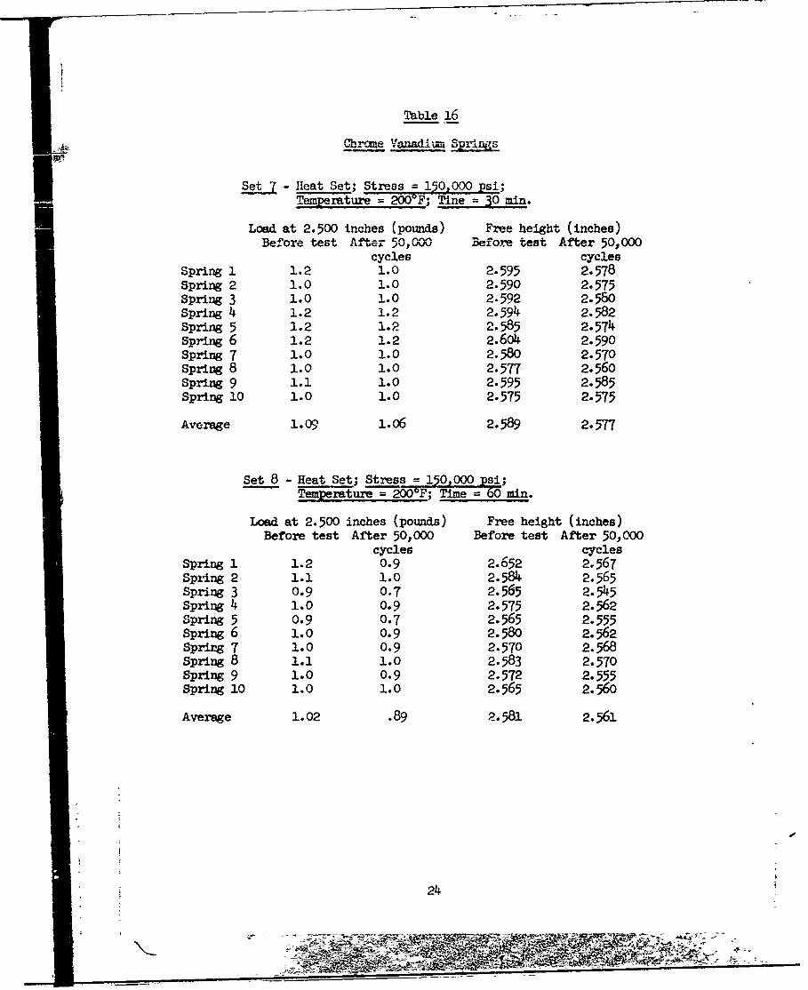
Table 16
Chrome Vanadlm Spings
S- Heat Set; Stress = 150,000 Psi;
Temperature = 200'F; Tie 0 min.
Load at 2.500 inches (pounds) Free height (inches)Before test After 50, w Before test After 50,000
cycles cyclesSpring 1 1.2 1.0 2.595 2.578Spring 2 1.0 1.0 2.590 2.575Spring 3 1.0 1.0 2.592 2.580spring 4 1.2 1.2 2.594 2.582Spring 5 1.2 1.2 2.585 2.574Spring 6 1.2 1.2 2.604 2.590Spring 7 1.0 1.0 2.580 2.570Spring 8 1.0 1.0 2.577 2.560Spring 9 1.1 1.0 2.595 2.585Spring 10 1.0 1.0 2.575 2.575
Average 1.09 1.06 2.589 2.577
Set 8 - Heat Set; Stress =150,000 psi;TeMrature = 200OF; Time = 60 min.
Load at 2.500 inches (pounds) Free height (inches)Before test After 50,000 Before test After 50,000
cycles cyclesSpring 1 1.2 0.9 2.652 2.567Sprlng 2 1.1 1.0 2.584 2.565Spring 3 0.9 0.7 2.565 2.545Spring 4 1.0 0.9 2.575 2.562Spring 5 0.9 0.7 2.565 2.555Spring 6 1.0 0.9 2.580 2.562Spring 7 1.0 0.9 2.570 2.568spring 8 1.1 . 1.0 2.583 2.570Spring 9 1.0 0.9 2.572 2.555Spring 10 1.0 1.0 2.565 2.56o
Average 1.02 .89 2.581 2.561
24
iw -M=-= R

: ~Table ]-
Chrome Vanadium Srings
Set 13 - Controlled Set; No heat setting applied
Load at 2.500 inchez (pounds) Free height (inches)Before test After 50,000 Before test After 50,000
cycles cyclesSpring 1 2.0 1.1 2.68o 2.596Spring 2 2.0 1.5 2.675 2.650Spring 3 1.7 1.3 2.657 2.615Spring 4 2.0 1.4 2.695 2.630Spring 5 1.9 1.4 2.675 2.634Spring 6 2.0 1.4 2.678 2.633Spring 7 1.7 1.1 2.655 2.580Spring 8 1.9 1.5 2.665 2.645spring 9 2.0 o. L. 2.682 2.630
Average 1.91 1.34 2.674 2.624
2
25
U's
41p,,- , > .•
4j 4
'S.-5- 4
4a9
•---.4.. ..
4.6-
4,
InI
en Q9A ,414
~ca(14o
4-J
A26 - -
VV44
C4 -I
~~ I-
I *~ U
9- W)
4J 4)4J
LK Il lz- I~ NZ K
4J
nflt _ _ _ _ _ _ _ VI0T
C4.
4.4W
4J
t-
WW1
~."S
o 0-
O 41
a=,) 'to 1
F- 4 a3 > 0
U).
4.)
'4-a
"N. Mt
M~
it~
i M
.sj- tq
o ý -
- -- --------- - - -~
FIGUREm
HETSTSRIGISALE NEDRAC ETR
?m97
- - '--r~s~.---0
DISTRIBUTION
Copies
A. Department of Defense
Office of the-Director of DefenseResearch & EngineeringATTN: Mr. J. C. BarrettRoom 3D-1085, The PentagonWashington, DC 20301 1
Defense Documentation CenterATTN: TIPDRCameron StationAlexandria, VA 22314 12
B. Department of the Army
CommanderU.S. Army Materiel Development & Readiness CommandATTN: DRCRD-TC5001 Eisenhower AvenueAlexandria, VA 22333 1
CommanderU.S. Army Avnament CommandATTN: DRSAR-RDP 1
DRSAR-PPDRSAR-PPI 1DRSAR-TDC 2
Rock Island, IL 61201
CommanderU.S. Army Electronics CommandATTN: DRSEL-'L-MEFt. Monmouth, NJ 07703 1
CommanderRock Island ArsenalATTN: SARRI-RLA 1
SARRI-RLE 1SARRI-RLS 1
SARRI-RLW 1SARRI-RLP-L 2SARRI-RLR 20
k SARRI-RLTRock Island, IL 61201
I1I
i S!
) s
DISTRIBUTION
Copies
CommanderU.S. Army ,Ilssflr CommandATTN: DRSNJ,-RP 2
ORS1i-RRS, My. R. E. Ely 1Lr-,.-!'I-RSM, Mi . Whellahan I
Rledsý.one Arsenal, AL '5809
Wuumnander.I.S. Army MERDC
ATTN: STSFB-G!.Ft. Belvoir, VA 2206'.
CommatiderU.S. Army Environmental Hygiene AgencyEdgew-nd Arsenal, MD 21G03
Comma ndf.rU.S. Army Medical Biomechanical Research LaboratoryATTN: LibraryFt. D•r•ick Bldg. 568Frederick, MD 21701
CommanderNatack LaboratoriesNatick, MA 01760
CommanderU.S. Army Aviation SchoolATTN: Office of the LibrarianFt. Rucker, AL 36362
DirectorJoint Military Packaging Training CenterATTN: DRXPT-PTAberdeen Proving Grcund, MD 21005
CommanderU.S. Army Tropic Test CenterATTN: STETC-MO-A Technical LibraryDrawer 942Ft. Clayton, Canal Zone 09827
CommanderTobyhanna Army DepotATTN: DRC Packaging, Storage &
* Containerization CenterTobyhanna, PA 18466
S2
_VM
DISTRIBUTION
CopiesCommanderU.S. Army Production Equipment AgencyATTN: DRXIBRock Island ArsenalRock Island, IL 61201 2
CommanderU.S. Army Tank-Automotive CommandATTN: DRSTA-RPL, Technical Library 1
DRSTA-RK, Materials Laboratory 1Warren, MI 48090
U.S. Army Research & Development Group (Europe)ATTN: Chief, Chemistry BranchFPO New York 09510 1
CommanderU.S. Army Research OfficeP.O. Box 12211Research Triangle Park, NC 27709 1
CommanderArmy Materials & Mechanics Research CenterATTN: DRXMR-PLWatertown, MA 02172 1
CommanderFrankford ArsenalATTN: SARFA-L1000 1
SARFA-C2500 1Philadelphia, PA 19137
CommanderPicatinny ArsenalATTN: Plastics & Packaging Lab 1
PLASTEC 1Dover, NJ 07801
CommanderEdgewood ArsenalATTN: SAREA-CL-AEdgewood, M , 21010 1
CommanderWatervliet Arsenal
.ATTN: 3ARWV-RDR 1SARWV-RDT, Library 1
Watervliet, NY 12189
S3
Ii i
7 -z ýFV ýP
DISTRIBUTION
Copies
C. Department of Navy
Office of Naval ResearchATTN: ONR-471Room 928, Ballston Tower No. 1Arlington, VA 22217
CommanderNaval Sea Systems CommandATTN: SEA-03 I
RRMA-54 ISP-271 I
Washington, DC 20362
CommanderNaval Supply Systems CommandATTN: NSUP-048Washington, DC 20376
CommanderU.S. Naval Surface Weapons CenterATTN: NDL-211Silver Springs, MD 20910
CommanderU.S. Naval Research LaboratoryATTN: NRL-2600Washington, DC 20375
CommanderU.S. Naval Ordnance Test StationATTN: Code 753 Technical LibraryChina Lake, CA 93555
CommanderMare Island Naval ShipyardATTN: Rubber LaboratoryVallejo, CA 94592
4 4
S4
(N
5DISTRIBUTION
Ccýies
0. Department of the Air Force
HQ USAF RDPRoom 4Q-313, The PentagonWashington, DC 20330
AFML/LTMWright-Patterson AFB, Oil 4533 2
AFML/MBWright-Patterson AFB, OH 45433
AFFTCEdwards AFB, CA 93523
E. Other Government Agencies
Energy Research and Development AgencyDivision of Reactor Development & TechnologyWashington, DC 20545
George C. Marshall Space Flight Center, NASAATTN: M-S&E 1
M-A&PS 1Huntsville, AL 35812
!S5

a4 4 z c
04 0 -0.0 0 .A %0 0
WA.- 0 v w o w .
:l0o 0"a "V . 44 04. 0 00
w t '-- 00 o ~ 4 o.4 0 C2 - '.-0
-00 t .4 -C~3 -0 441 00 04
-- ~~~~~ ~ o.e. oft.0 44044
'to -4 . 1a"0 0
0444w cc4 4 ' . 4ow 44 444 2 44
44404 g44444a 0 n
kw 0 N... Or W, > Vm 0 W-4 t 0 c44Ia~~ w40.6(4 44040
440-4Is 40 0 -oo w4 04
0- y44 0 44.%4 0.44 4
0 44004
0 4 Z . C 4 4 4 4 ' 440 4 4. a04 . 04 . 0 40.0 j 44044 444.0 c 44 . 0. w 4
4444444 440. u 20 6~~~~~~ .0 i5~
0 4 600 ~~ ~ 4 4WA A 0 o ~ .3'w' 9,120 9 Z~4 .cc
ta 's
C-3.444 t rao
oz . lo r o 4 4 44 0 4 4
044~ 40 Qo v444140
a-. ~~~~~r w.*r44.4,0 U444 0.4 a4.0. 0.444 .. 144 0 **4 000. 4.4 0441 4 V. 00 4.0 .0 4 44 444 44.0 4~04
6014 0.4 4 ~ - ~ 04 ~ 44 40 ' . ~ 0 0 .0 4.04 .4 440~ ~ 44 0 44 ~ 44. 40..cc,4
be 60 44
40 4
1-4 2 1 -
r4 40 rai at4 40 0 a -'