heat shrink formation of a corrugated thin film
TRANSCRIPT
Heat shrink formation of a corrugated thin film thermoelectricgenerator
Tianlei Sun a, Jennifer L. Peavey b, M. David Shelby b, Scott Ferguson a, Brendan T. O’Connor a,⇑a North Carolina State University, Department of Mechanical and Aerospace Engineering, 911 Oval Dr., Raleigh, NC 27695, United Statesb Eastman Chemical Company, PO Box 431, Kingsport, TN 37662-0431, United States
a r t i c l e i n f o
Article history:Received 28 April 2015Accepted 5 July 2015Available online 16 July 2015
Keywords:Thermoelectric generatorThin filmIn-plane heat transferCorrugated architecture
a b s t r a c t
A thin film thermoelectric (TE) generator with a corrugated architecture is demonstrated formed using aheat-shrink fabrication approach. Fabrication of the corrugated TE structure consists of depositing thinfilm thermoelectric elements onto a planar non-shrink polyimide substrate that is then sandwichedbetween two uniaxial stretch-oriented co-polyester (PET) films. The heat shrink PET films are adheredto the polyimide in select locations, such that when the structure is placed in a high temperature envi-ronment, the outer films shrink resulting in a corrugated core film and thermoelectric elements spanningbetween the outer PET films. The module has a cross-plane heat transfer architecture similar to a conven-tional bulk TE module, but with heat transfer in the plane of the thin film thermoelectric elements, whichassists in maintaining a significant temperature difference across the thermoelectric junctions. In thisdemonstration, Ag and Ni films are used as the thermoelectric elements and a Seebeck coefficient of14 lV K�1 is measured with a maximum power output of 0.22 nW per couple at a temperature differenceof 7.0 K. We then theoretically consider the performance of this device architecture with high perfor-mance thermoelectric materials in the heat sink limited regime. The results show that the heat-shrinkapproach is a simple fabrication method that may be advantageous in large-area, low power densityapplications. The fabrication method is also compatible with simple geometric modification to achievevarious form factors and power densities to customize the TE generator for a range of applications.
� 2015 Elsevier Ltd. All rights reserved.
1. Introduction
The direct conversion of thermal energy to electrical powerwithout moving parts makes thermoelectric generators (TEG) ahighly attractive energy conversion technology. These devices alsohave the advantage of having a small volume, and the ability toconvert energy over a broad temperature range. However, to datethere has been limited commercial adoption of TEGs due to highmodule costs and relative poor efficiency compared to other tech-nologies. Recently, significant efforts have focused on developingthermoelectric (TE) materials with increased efficiency throughimproving the TE element’s dimensionless figure of merit,ZT = S2rTj�1, where S, r, T and j are the Seebeck coefficient, elec-trical conductivity, absolute temperature, and thermal conductiv-ity, respectively [1]. The ZT value provides an upper limit on TEpower conversion efficiency and is thus a key optimization param-eter [2]. Currently, there have been numerous demonstrations ofthermoelectric materials with ZT values greater than 2 [3,4].
However, TEGs based on these materials will struggle to becomecost effective [5]. Alternatively, low-cost thermoelectric materialsbased on organic and organic–inorganic hybrid systems are beingdeveloped that have recently shown promising cost-performancemetrics [5,6]. Conjugated polymers have been developed with ZTas high as 0.4 [7], and hybrid solution processed materials havebeen shown to have ZT values as high as 0.1 [8].
While improving ZT is critical for cost competitiveness, otheraspects of TEG design must also be considered to ensure low costand high performance systems [9,10]. In particular, it is highlyadvantageous to develop TEG modules that are compatible withlow-cost processing methods and to develop modules that do nothave elaborate heat sink demands [11]. Low-cost TE processinghas focused on thin-film materials that are compatible withroll-to-roll processing [12–14]. For these thin-film elements, heattransfer across the plane of the film (cross-plane TEs) is the mostcommon module architecture [15,16]. However, maintaining alarge temperature difference across the thin film junctions (andthus increasing power output) becomes a challenge [11]. Thin filmTEGs can also be designed such that heat transfer occurs in theplane of the film (in-plane TEs) [17–19]. However, this design is
http://dx.doi.org/10.1016/j.enconman.2015.07.0160196-8904/� 2015 Elsevier Ltd. All rights reserved.
⇑ Corresponding author.E-mail address: [email protected] (B.T. O’Connor).
Energy Conversion and Management 103 (2015) 674–680
Contents lists available at ScienceDirect
Energy Conversion and Management
journal homepage: www.elsevier .com/locate /enconman
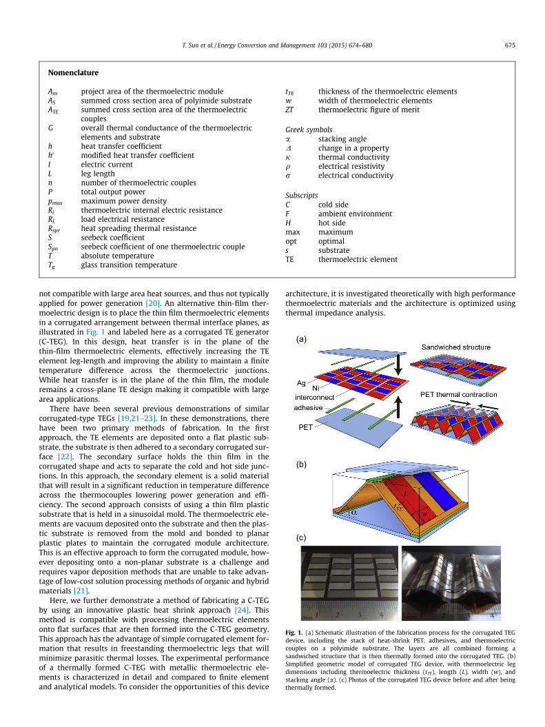
not compatible with large area heat sources, and thus not typicallyapplied for power generation [20]. An alternative thin-film ther-moelectric design is to place the thin film thermoelectric elementsin a corrugated arrangement between thermal interface planes, asillustrated in Fig. 1 and labeled here as a corrugated TE generator(C-TEG). In this design, heat transfer is in the plane of thethin-film thermoelectric elements, effectively increasing the TEelement leg-length and improving the ability to maintain a finitetemperature difference across the thermoelectric junctions.While heat transfer is in the plane of the thin film, the moduleremains a cross-plane TE design making it compatible with largearea applications.
There have been several previous demonstrations of similarcorrugated-type TEGs [19,21–23]. In these demonstrations, therehave been two primary methods of fabrication. In the firstapproach, the TE elements are deposited onto a flat plastic sub-strate, the substrate is then adhered to a secondary corrugated sur-face [22]. The secondary surface holds the thin film in thecorrugated shape and acts to separate the cold and hot side junc-tions. In this approach, the secondary element is a solid materialthat will result in a significant reduction in temperature differenceacross the thermocouples lowering power generation and effi-ciency. The second approach consists of using a thin film plasticsubstrate that is held in a sinusoidal mold. The thermoelectric ele-ments are vacuum deposited onto the substrate and then the plas-tic substrate is removed from the mold and bonded to planarplastic plates to maintain the corrugated module architecture.This is an effective approach to form the corrugated module, how-ever depositing onto a non-planar substrate is a challenge andrequires vapor deposition methods that are unable to take advan-tage of low-cost solution processing methods of organic and hybridmaterials [21].
Here, we further demonstrate a method of fabricating a C-TEGby using an innovative plastic heat shrink approach [24]. Thismethod is compatible with processing thermoelectric elementsonto flat surfaces that are then formed into the C-TEG geometry.This approach has the advantage of simple corrugated element for-mation that results in freestanding thermoelectric legs that willminimize parasitic thermal losses. The experimental performanceof a thermally formed C-TEG with metallic thermoelectric ele-ments is characterized in detail and compared to finite elementand analytical models. To consider the opportunities of this device
architecture, it is investigated theoretically with high performancethermoelectric materials and the architecture is optimized usingthermal impedance analysis.
Nomenclature
Am project area of the thermoelectric moduleAS summed cross section area of polyimide substrateATE summed cross section area of the thermoelectric
couplesG overall thermal conductance of the thermoelectric
elements and substrateh heat transfer coefficienth0 modified heat transfer coefficientI electric currentL leg lengthn number of thermoelectric couplesP total output powerpmax maximum power densityRi thermoelectric internal electric resistanceRL load electrical resistanceRspr heat spreading thermal resistanceS seebeck coefficientSpn seebeck coefficient of one thermoelectric coupleT absolute temperatureTg glass transition temperature
tTE thickness of the thermoelectric elementsw width of thermoelectric elementsZT thermoelectric figure of merit
Greek symbolsa stacking angleD change in a propertyj thermal conductivityq electrical resistivityr electrical conductivity
SubscriptsC cold sideF ambient environmentH hot sidemax maximumopt optimals substrateTE thermoelectric element
Fig. 1. (a) Schematic illustration of the fabrication process for the corrugated TEGdevice, including the stack of heat-shrink PET, adhesives, and thermoelectriccouples on a polyimide substrate. The layers are all combined forming asandwiched structure that is then thermally formed into the corrugated TEG. (b)Simplified geometric model of corrugated TEG device, with thermoelectric legdimensions including thermoelectric thickness (tTE), length (L), width (w), andstacking angle (a). (c) Photos of the corrugated TEG device before and after beingthermally formed.
T. Sun et al. / Energy Conversion and Management 103 (2015) 674–680 675
2. Corrugated thermoelectric module fabrication
A schematic of the fabrication process, and final structure isillustrated in Fig. 1(a). For proof-of-concept purposes, the thermo-electric elements consisted of Ag and Ni thin films deposited byvacuum thermal evaporation onto a 130-lm thick polyimide sub-strate, and patterned using a shadow mask. The polyimide film wasthe core layer of the TEG module and the support for the thin-filmthermoelectric legs. The thermoelectric elements were 140-nmthick, 4-mm wide and variable in length. The thermoelectric legswere electrically connected laterally in a row and then betweenrows at the last TE elements with Ag thin films, as illustrated inFig. 1(a) and pictured in Fig. 1(c). There was approximately0.5 mm overlap of the metallic elements to form the electricaljunctions. The non-shrink polyimide core was then attached toheat-shrink polyester (PET) films on each side of the polyimidewith polymer adhesive placed between the rows of the thermocou-ples in alternating fashion. The outer layers were uniaxialstretch-oriented having a glass transition temperature (Tg) ofapproximately 345 K. The outer layers were extruded to createthe un-oriented base material and then uniaxially stretched at atemperature of approximately 355 K [24]. The three layer planarcomposite structure was then placed in a vacuum oven at 383 Kcausing the PET sheets to shrink and forcing the polyimide inter-layer to form and maintain a sinusoidal shape. In this demonstra-tion, 630-lm thick PET films were stretched by 33%, resulting infilms with a shrink of approximately 25% after heating. An exampleof the fabricated hybrid TEG is pictured in Fig. 1(c) and is composedof three and a half Ag-Ni couples per row with legs that are 12 mmlong and 4 mm wide. Note that Ag and Ni were chosen for theirgood thermoelectric properties among metals. These materialsare also ductile and adhere well to the polyimide allowing forbending during TEG formation without mechanical failure.
3. Results and discussion
3.1. Performance analysis
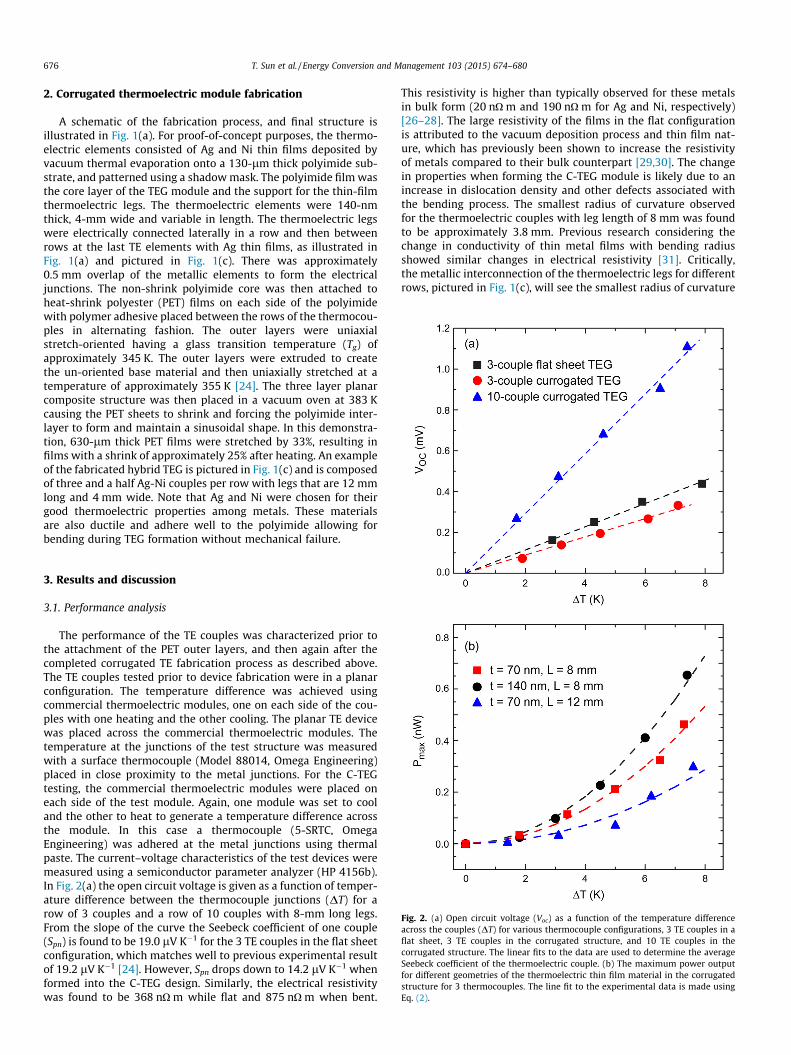
The performance of the TE couples was characterized prior tothe attachment of the PET outer layers, and then again after thecompleted corrugated TE fabrication process as described above.The TE couples tested prior to device fabrication were in a planarconfiguration. The temperature difference was achieved usingcommercial thermoelectric modules, one on each side of the cou-ples with one heating and the other cooling. The planar TE devicewas placed across the commercial thermoelectric modules. Thetemperature at the junctions of the test structure was measuredwith a surface thermocouple (Model 88014, Omega Engineering)placed in close proximity to the metal junctions. For the C-TEGtesting, the commercial thermoelectric modules were placed oneach side of the test module. Again, one module was set to cooland the other to heat to generate a temperature difference acrossthe module. In this case a thermocouple (5-SRTC, OmegaEngineering) was adhered at the metal junctions using thermalpaste. The current–voltage characteristics of the test devices weremeasured using a semiconductor parameter analyzer (HP 4156b).In Fig. 2(a) the open circuit voltage is given as a function of temper-ature difference between the thermocouple junctions (DT) for arow of 3 couples and a row of 10 couples with 8-mm long legs.From the slope of the curve the Seebeck coefficient of one couple(Spn) is found to be 19.0 lV K�1 for the 3 TE couples in the flat sheetconfiguration, which matches well to previous experimental resultof 19.2 lV K�1 [24]. However, Spn drops down to 14.2 lV K�1 whenformed into the C-TEG design. Similarly, the electrical resistivitywas found to be 368 nO m while flat and 875 nO m when bent.
This resistivity is higher than typically observed for these metalsin bulk form (20 nO m and 190 nO m for Ag and Ni, respectively)[26–28]. The large resistivity of the films in the flat configurationis attributed to the vacuum deposition process and thin film nat-ure, which has previously been shown to increase the resistivityof metals compared to their bulk counterpart [29,30]. The changein properties when forming the C-TEG module is likely due to anincrease in dislocation density and other defects associated withthe bending process. The smallest radius of curvature observedfor the thermoelectric couples with leg length of 8 mm was foundto be approximately 3.8 mm. Previous research considering thechange in conductivity of thin metal films with bending radiusshowed similar changes in electrical resistivity [31]. Critically,the metallic interconnection of the thermoelectric legs for differentrows, pictured in Fig. 1(c), will see the smallest radius of curvature
Fig. 2. (a) Open circuit voltage (Voc) as a function of the temperature differenceacross the couples (DT) for various thermocouple configurations, 3 TE couples in aflat sheet, 3 TE couples in the corrugated structure, and 10 TE couples in thecorrugated structure. The linear fits to the data are used to determine the averageSeebeck coefficient of the thermoelectric couple. (b) The maximum power outputfor different geometries of the thermoelectric thin film material in the corrugatedstructure for 3 thermocouples. The line fit to the experimental data is made usingEq. (2).
676 T. Sun et al. / Energy Conversion and Management 103 (2015) 674–680

and the metal film will be in contact with the polymer adhesive. Todetermine if this has a large impact on performance, the Seebeckcoefficient was measured across 10 thermocouples over multiplerows, which includes the interconnecting Ag film between rows.The average Spn was found to be 14.0 lV K�1 per couple, showingnegligible performance loss associated with this interconnection.
The output voltage and output power for 3 TE couples in onerow of the C-TEG was investigated experimentally and with finiteelement numerical simulation using ANSYS [32], for a DT of 7.0 K.The finite element model consisted of 598,225 nodes and 295,719elements using an auto-generated mesh. The model assumes pla-nar legs as illustrated in Fig. 1(b). The difference in the finite ele-ment model output using sinusoidal legs and the straight legapproximation has previously been shown to be negligible [33].Experimentally, the maximum output power was found to beapproximately 0.67 nW at a current of 4.1 lA, as shown in Fig. 3.The result from the finite element simulation matches well withthe experimental measurement, with a maximum output powerof 0.65 nW. Generally, the total output power (P) of TEGs can begiven by [11],
P ¼nSpnDT� �2RL
Ri þ RLð Þ2; ð1Þ
where n is the number of the TE couples, Ri is the TEG internal elec-trical resistance and RL is the load electrical resistance. The maxi-mum output power occurs when the load electrical resistance isequal to the internal electrical resistance of TEG resulting in,
Pmax ¼nSpnDT� �2
4Ri: ð2Þ
The geometry of the TE couples directly impacts the maximumoutput power due to Ri given by,
Ri ¼qL
wtTE; ð3Þ
where q is the combined electrical resistivity, L is the leg length, wis width of TE elements and tTE is thickness of the elements. Theexperimental maximum output power with variation in tempera-ture difference for various L/tTE ratios is given in Fig. 2(b) and iscompared to the predicted power from Eq. (2). It is found thatPmax increases with DT following a parabolic relationship asexpected. It is clear that the thicker film and shorter leg lengthresult in high power output following the relationship that powerdensity is proportional to (wtTE)/L, as given by Eq. (2) [34].
3.2. Theoretical performance optimization
The geometry of the experimentally demonstrated moduleswas selected based on availability of pre-stretched PET, stabilityof the thermally formed corrugated film, and ability to easily probethe temperature profile across the thermocouples. However, theresulting modules may not be the optimal geometry for powergeneration. Similarly, high performance materials may beemployed as long as bending during fabrication does not signifi-cantly impact their properties. With this in mind, a dimensionaland material analysis is theoretically conducted on the C-TEGdesign to consider the performance potential of this architecture.With the goal of minimizing the system cost, it is expected thatthe module will operate in the heat sink limited regime [9,11].The TEG is heat sink limited when the output power of the systemis limited by the ability to transfer heat to or away from the ther-moelectric couples. This would be expected for a TEG system with-out elaborate heat sink designs. Here, the TEG performance isoptimized under the conditions of a constant hot side temperatureof the thermoelectric couple (TH), and heat rejection being limited
by natural convection [9,11]. Optimal performance of this systemis found under thermal impedance matching conditions. Detailsof this approach have been previously described [9,11]. Here, weprovide a brief review of the analysis method. In thermoelectricoperation, the convective heat transfer from the cold side of themodule is equivalent to the summed conduction through the mod-ule, Peltier heat transfer, and joule heating, given by,
hAmðTC � TFÞ ¼ GðTH � TCÞ þ SpnTCI þ 12
I2Ri; ð4Þ
where h is the heat transfer coefficient, Am is the projected area ofthe TEG module, TC is the cold side temperature of the TE couple,TF is the environment temperature, I is electric current, and G isoverall thermal conductance of the TE elements and substrate givenby,
G ¼ jTEATE
Lþ jsAs
L; ð5Þ
where jTE is the thermal conductivity of the TE element, ATE is thesummed cross section area of the TE couples, js is the thermal
Fig. 3. (a) Voltage output (V) and (b) power output (P) of 3-couples of the C-TEG asfunction of current (I) for a temperature difference across the couples (DT) of 7.0 K.The measurement is compared to numerical finite element simulations.
T. Sun et al. / Energy Conversion and Management 103 (2015) 674–680 677
conductivity of the polyimide substrate and As is the summed crosssection area of the polyimide substrate. To simplify the calculation,Peltier heat transfer and joule heating, which are relatively smallcompared with heat conduction are neglected [11] resulting in,
hAmðTC � TFÞ � GðTH � TCÞ: ð6Þ
The design of the C-TEG module will typically result in a lowareal packing density of thermoelectric elements as compared toa conventional bulk TEG. This requires that the thermal resistancecaused by heat spreading also be included in the optimization.Heat spreading occurs when heat flows through materials thathave a change in cross-sectional area [35], which in our case hap-pens when heat flows between the outer PET films and the thermo-electric legs. The thermal resistance associated with heat spreadingcan be accounted for by modifying the heat transfer coefficient hresulting in a modified heat transfer coefficient h0 given by[11,35,36],
h0 ¼ 1AmRspr þ 1=h
; ð7Þ
where Rspr is the heat spreading resistance. One important factoraffecting Rspr is thermal conductivity of the outer layer material,which in our case is PET [35]. Applying a high thermal conductivitymaterial will dramatically decrease the heat spreading capacity andthus increase the overall power density. A possible approach is tocoat a metal layer on the exterior of the PET layer to minimize heatspreading resistance. Combining Eqs. (2), (6) and (7), the maximumpower density (pmax) is given as,
pmax ¼h02Am TH � TFð Þ2S2
pnATE
4 h0Am þ G� �2
Lq: ð8Þ
In this analysis, TH = 302 K, TF = 295 K, and h = 5 W m�2 K�1. Theheat transfer coefficient represents natural convection of a verticalplate in air with a modest temperature difference between TC andTF [37].
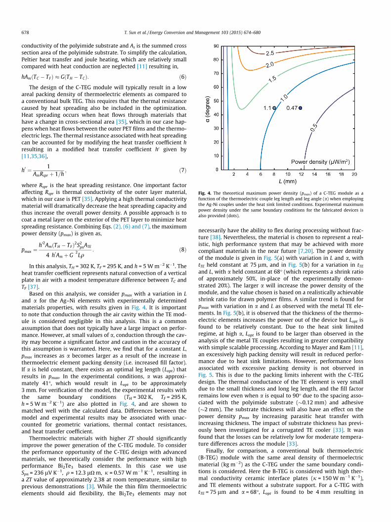
Based on this analysis, we consider pmax with a variation in Land a for the Ag–Ni elements with experimentally determinedmaterials properties, with results given in Fig. 4. It is importantto note that conduction through the air cavity within the TE mod-ule is considered negligible in this analysis. This is a commonassumption that does not typically have a large impact on perfor-mance. However, at small values of a, conduction through the cav-ity may become a significant factor and caution in the accuracy ofthis assumption is warranted. Here, we find that for a constant L,pmax increases as a becomes larger as a result of the increase inthermoelectric element packing density (i.e. increased fill factor).If a is held constant, there exists an optimal leg length (Lopt) thatresults in pmax. In the experimental conditions, a was approxi-mately 41�, which would result in Lopt to be approximately3 mm. For verification of the model, the experimental results withthe same boundary conditions (TH = 302 K, TF = 295 K,h = 5 W m�2 K�1) are also plotted in Fig. 4, and are shown tomatched well with the calculated data. Differences between themodel and experimental results may be associated with unac-counted for geometric variations, thermal contact resistances,and heat transfer coefficient.
Thermoelectric materials with higher ZT should significantlyimprove the power generation of the C-TEG module. To considerthe performance opportunity of the C-TEG design with advancedmaterials, we theoretically consider the performance with highperformance Bi2Te3 based elements. In this case we useSpn = 236 lV K�1, q = 12.3 lO m, j = 0.57 W m�1 K�1, resulting ina ZT value of approximately 2.38 at room temperature, similar toprevious demonstrations [3]. While the thin film thermoelectricelements should aid flexibility, the Bi2Te3 elements may not
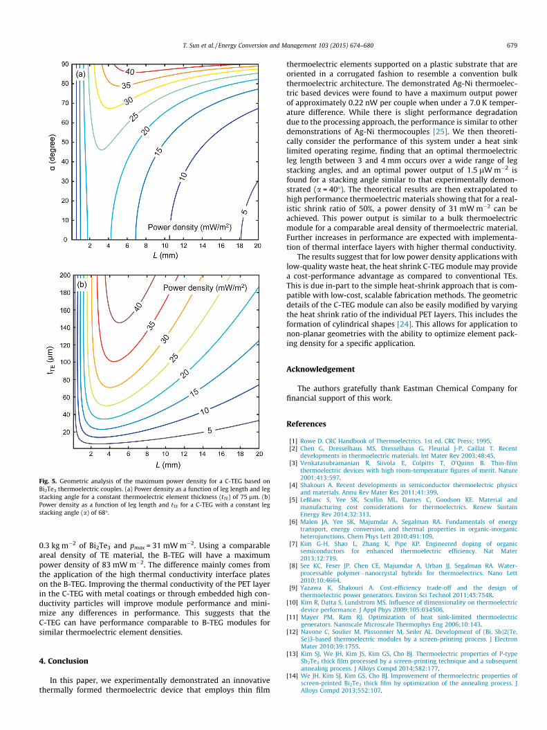
necessarily have the ability to flex during processing without frac-ture [38]. Nevertheless, the material is chosen to represent a real-istic, high performance system that may be achieved with morecompliant materials in the near future [7,20]. The power densityof the module is given in Fig. 5(a) with variation in L and a, withtTE held constant at 75 lm, and in Fig. 5(b) for a variation in tTE
and L, with a held constant at 68� (which represents a shrink ratioof approximately 50%, in-place of the experimentally demon-strated 20%). The larger a will increase the power density of themodule, and the value chosen is based on a realistically achievableshrink ratio for drawn polymer films. A similar trend is found forpmax with variation in a and L as observed with the metal TE ele-ments. In Fig. 5(b), it is observed that the thickness of the thermo-electric elements increases the power out of the device but Lopt isfound to be relatively constant. Due to the heat sink limitedregime, at high a, Lopt is found to be larger than observed in theanalysis of the metal TE couples resulting in greater compatibilitywith simple scalable processing. According to Mayer and Ram [11],an excessively high packing density will result in reduced perfor-mance due to heat sink limitations. However, performance lossassociated with excessive packing density is not observed inFig. 5. This is due to the packing limits inherent with the C-TEGdesign. The thermal conductance of the TE element is very smalldue to the small thickness and long leg length, and the fill factorremains low even when a is equal to 90� due to the spacing asso-ciated with the polyimide substrate (�0.12 mm) and adhesive(�2 mm). The substrate thickness will also have an effect on thepower density pmax by increasing parasitic heat transfer withincreasing thickness. The impact of substrate thickness has previ-ously been investigated for a corrugated TE cooler [33]. It wasfound that the losses can be relatively low for moderate tempera-ture differences across the module [33].
Finally, for comparison, a conventional bulk thermoelectric(B-TEG) module with the same areal density of thermoelectricmaterial (kg m�2) as the C-TEG under the same boundary condi-tions is considered. Here the B-TEG is considered with high ther-mal conductivity ceramic interface plates (j = 150 W m�1 K�1),and TE elements without a substrate support. For a C-TEG withtTE = 75 lm and a = 68�, Lopt is found to be 4 mm resulting in
Fig. 4. The theoretical maximum power density (pmax) of a C-TEG module as afunction of the thermoelectric couple leg length and leg angle (a) when employingthe Ag-Ni couples under the heat sink limited conditions. Experimental maximumpower density under the same boundary conditions for the fabricated devices isalso provided (dots).
678 T. Sun et al. / Energy Conversion and Management 103 (2015) 674–680
0.3 kg m�2 of Bi2Te3 and pmax = 31 mW m�2. Using a comparableareal density of TE material, the B-TEG will have a maximumpower density of 83 mW m�2. The difference mainly comes fromthe application of the high thermal conductivity interface plateson the B-TEG. Improving the thermal conductivity of the PET layerin the C-TEG with metal coatings or through embedded high con-ductivity particles will improve module performance and mini-mize any differences in performance. This suggests that theC-TEG can have performance comparable to B-TEG modules forsimilar thermoelectric element densities.
4. Conclusion
In this paper, we experimentally demonstrated an innovativethermally formed thermoelectric device that employs thin film
thermoelectric elements supported on a plastic substrate that areoriented in a corrugated fashion to resemble a convention bulkthermoelectric architecture. The demonstrated Ag-Ni thermoelec-tric based devices were found to have a maximum output powerof approximately 0.22 nW per couple when under a 7.0 K temper-ature difference. While there is slight performance degradationdue to the processing approach, the performance is similar to otherdemonstrations of Ag-Ni thermocouples [25]. We then theoreti-cally consider the performance of this system under a heat sinklimited operating regime, finding that an optimal thermoelectricleg length between 3 and 4 mm occurs over a wide range of legstacking angles, and an optimal power output of 1.5 lW m�2 isfound for a stacking angle similar to that experimentally demon-strated (a = 40�). The theoretical results are then extrapolated tohigh performance thermoelectric materials showing that for a real-istic shrink ratio of 50%, a power density of 31 mW m�2 can beachieved. This power output is similar to a bulk thermoelectricmodule for a comparable areal density of thermoelectric material.Further increases in performance are expected with implementa-tion of thermal interface layers with higher thermal conductivity.
The results suggest that for low power density applications withlow-quality waste heat, the heat shrink C-TEG module may providea cost-performance advantage as compared to conventional TEs.This is due in-part to the simple heat-shrink approach that is com-patible with low-cost, scalable fabrication methods. The geometricdetails of the C-TEG module can also be easily modified by varyingthe heat shrink ratio of the individual PET layers. This includes theformation of cylindrical shapes [24]. This allows for application tonon-planar geometries with the ability to optimize element pack-ing density for a specific application.
Acknowledgement
The authors gratefully thank Eastman Chemical Company forfinancial support of this work.
References
[1] Rowe D. CRC Handbook of Thermoelectrics. 1st ed. CRC Press; 1995.[2] Chen G, Dresselhaus MS, Dresselhaus G, Fleurial J-P, Caillat T. Recent
developments in thermoelectric materials. Int Mater Rev 2003;48:45.[3] Venkatasubramanian R, Siivola E, Colpitts T, O’Quinn B. Thin-film
thermoelectric devices with high room-temperature figures of merit. Nature2001;413:597.
[4] Shakouri A. Recent developments in semiconductor thermoelectric physicsand materials. Annu Rev Mater Res 2011;41:399.
[5] LeBlanc S, Yee SK, Scullin ML, Dames C, Goodson KE. Material andmanufacturing cost considerations for thermoelectrics. Renew SustainEnergy Rev 2014;32:313.
[6] Malen JA, Yee SK, Majumdar A, Segalman RA. Fundamentals of energytransport, energy conversion, and thermal properties in organic-inorganicheterojunctions. Chem Phys Lett 2010;491:109.
[7] Kim G-H, Shao L, Zhang K, Pipe KP. Engineered doping of organicsemiconductors for enhanced thermoelectric efficiency. Nat Mater2013;12:719.
[8] See KC, Feser JP, Chen CE, Majumdar A, Urban JJ, Segalman RA. Water-processable polymer�nanocrystal hybrids for thermoelectrics. Nano Lett2010;10:4664.
[9] Yazawa K, Shakouri A. Cost-efficiency trade-off and the design ofthermoelectric power generators. Environ Sci Technol 2011;45:7548.
[10] Kim R, Datta S, Lundstrom MS. Influence of dimensionality on thermoelectricdevice performance. J Appl Phys 2009;105:034506.
[11] Mayer PM, Ram RJ. Optimization of heat sink-limited thermoelectricgenerators. Nanoscale Microscale Thermophys Eng 2006;10:143.
[12] Navone C, Soulier M, Plissonnier M, Seiler AL. Development of (Bi, Sb)2(Te,Se)3-based thermoelectric modules by a screen-printing process. J ElectronMater 2010;39:1755.
[13] Kim SJ, We JH, Kim JS, Kim GS, Cho BJ. Thermoelectric properties of P-typeSb2Te3 thick film processed by a screen-printing technique and a subsequentannealing process. J Alloys Compd 2014;582:177.
[14] We JH, Kim SJ, Kim GS, Cho BJ. Improvement of thermoelectric properties ofscreen-printed Bi2Te3 thick film by optimization of the annealing process. JAlloys Compd 2013;552:107.
Fig. 5. Geometric analysis of the maximum power density for a C-TEG based onBi2Te3 thermoelectric couples. (a) Power density as a function of leg length and legstacking angle for a constant thermoelectric element thickness (tTE) of 75 lm. (b)Power density as a function of leg length and tTE for a C-TEG with a constant legstacking angle (a) of 68�.
T. Sun et al. / Energy Conversion and Management 103 (2015) 674–680 679

[15] Lee H-B, Yang HJ, We JH, Kim K, Choi KC, Cho BJ. Thin-film thermoelectricmodule for power generator applications using a screen-printing method. JElectron Mater 2011;40:615.
[16] Budak S, Smith C, Muntele C, Chhay B, Herdary K, Johnson RB, et al.Thermoelectric properties of SiO2/SiO2+ CoSb multi-nanolayered thin filmsmodified by MeV Si ions. J Intell Mater Syst Struct 2012;24:1350.
[17] Madan D, Wang Z, Chen A, Wright PK, Evans JW. High-performance dispenserprinted MA P-type Bi(0.5)Sb(1.5)Te(3) flexible thermoelectric generators forpowering wireless sensor networks. ACS Appl Mater Interfaces 2013;5:11872.
[18] Wüsten J, Potje-Kamloth K. Organic thermogenerators for energy autarkicsystems on flexible substrates. J Phys D Appl Phys 2008;41:135113.
[19] Fan P, Zheng Z-H, Cai Z-K, Chen T-B, Liu P-J, Cai X-M, et al. The highperformance of a thin film thermoelectric generator with heat flow runningparallel to film surface. Appl Phys Lett 2013;102:033904.
[20] Bubnova O, Crispin X. Towards polymer-based organic thermoelectricgenerators. Energy Environ Sci 2012;5:9345.
[21] Itoigawa K, Ueno H, Shiozaki M, Toriyama T, Sugiyama S. Fabrication of flexiblethermopile generator. J Micromech Microeng 2005;15:S233.
[22] Kim H, Park S-G, Jung B, Hwang J, Kim W. New device architecture of athermoelectric energy conversion for recovering low-quality heat. Appl Phys A2013;114:1201.
[23] Francioso L, De Pascali C, Siciliano P, De Risi A, D’Amico S, Veri C et al. Thin filmtechnology flexible thermoelectric generator and dedicated ASIC for energyharvesting applications. In: 5th IEEE Int Work Adv Sensors Interfaces IWASI104; 2013.
[24] Shelby MD, Clear S. Self-corrugating laminates and methods of making them,US Pat. App. 13/965,288, March 27, 2014.
[25] Yadav A, Pipe KP, Shtein M. Fiber-based flexible thermoelectric powergenerator. J Power Sources 2008;175:909.
[26] Gergen B, Nienhaus H, Weinberg WH, McFarland EM. Morphologicalinvestigation of ultrathin Ag and Ti films grown on hydrogen terminated Si(111). J Vac Sci Technol, B 2000;18:2401.
[27] Maréchal N. Characterization of silver films deposited by radio frequencymagnetron sputtering. J Vac Sci Technol, A 1994;12:707.
[28] Gray D. American institute of physics handbook. 3rd ed. McGraw-Hill; 1982.[29] Paddock CA, Eesley GL. Transient thermoreflectance from thin metal films. J
Appl Phys 1986;60:285.[30] Logeeswaran VJ, Kobayashi NP, Islam MS, Wu W, Chaturvedi P, Fang NX, et al.
Ultrasmooth silver thin films deposited with a germanium nucleation layer.Nano Lett 2009;9:178.
[31] Parker RL, Krinsky A. Electrical resistance-strain characteristics of thinevaporated metal films. J Appl Phys 1963;34:2700.
[32] Antonova E, Looman D. Finite elements for thermoelectric device analysis inANSYS. Int Conf Thermoelect 2005;200.
[33] Owoyele O, Ferguson S, O’Connor BT. Performance analysis of a thermoelectriccooler with a corrugated architecture. Appl Energy 2015;147:184.
[34] Rowe D, Min G. Evaluation of thermoelectric modules for power generation. JPower Sources 1998;73:193.
[35] Lee S, Song S, Au V, Moran K. Constriction/spreading resistance model forelectronics packaging. Proc ASME/JSME Therm Eng Conf 1995;4:199.
[36] Song S, Lee S, Au V. Closed-form equation for thermal constriction/spreadingresistances with variable resistance boundary condition. In: Proc IEPS ConfAtlanta GA, vol. 4; 1994. p. 111.
[37] Incropera FP, DeWitt DP. Introduction to heat transfer. 6th ed. Wiley; 2011.[38] Shiozaki M, Sugiyama S, Watanabe N, Ueno H, Itoigawa K. Flexible thin-film
BiTe thermopile for room temperature power generation. In: 19th IEEEinternational conference on micro electro mechanical systems, Istanbul; 2006.
680 T. Sun et al. / Energy Conversion and Management 103 (2015) 674–680

ID Title Pages
771750 Heatshrinkformationofacorrugatedthinfilmthermoelectricgenerator 7
http://fulltext.study/journal/737
http://FullText.Study