heat shrink tubes and accessories cable … · cable joints and terminations cable accessories ww....
TRANSCRIPT
HEAT SHRINK TUBES AND ACCESSORIESCABLE JOINTS AND TERMINATIONS
CABLE ACCESSORIES
ww
1
TABLE OF CONTENTS
HEAT SHRINK TUBESAND ACCESSORIES
PROPERTIES
Radiation crosslinked polyolefin 5
INSTALLATION MANUALS, TECHNICAL DETAILS AND OPERATIONAL PROPERTIES OF HEAT SHRINK TUBES
Installation of heat shrink tubes thin wall, medium wall and thick wall 6Installation of heat shrink tube of large diameter on posts (renovation) 6Technical details and operational properties of heat shrink tubes
HEAT SHRINK THIN WALL TUBES
Heat shrink thin wall tubes, heat-resistant - type +125°C - typu RCH1 8Heat shrink thin wall tubes, flexible, heat-resistant +125°C - type RCEH1 10Heat shrink thin wall tubes, self-extinguishing, heat-resistant +125°C - type RCH1S 12Heat shrink thin wall tubes, flexible, self-extinguishing, quick-shrink, heat-resistant +125°C - type RCEH1S 13Heat shrink thin wall tubes, flexible, self-extinguishing, quick-shrink, heat-resistant +135°C - type RCEH2S 14Polyolefin heat shrink tubes, very flexible, self-extinguishing, shrink ratio 3:1 and 4:1 - type RC3S and RC4S 16Heat shrinkable tubes for thermotransfer printing, thin wall tubes, very flexible, self-extinguishing, halogen-free - type RC2S(HF), RC3S(HF) 17Polyolefin heat shrink tubes, ultra thin - type RUC 18
THIN WALL TUBES WITH ADHESIVE
Thin wall heat shrink tubes, heat-resistant +125 +135°C with adhesive - type RCKH1 i RCEH2KS 19Polyolefin heat shrink tubes, very flexible, adhesive-layered, shrink ratio 3:1, 4:1 - RC3K and RC4K 20
DIY HEAT SHRINK KITS
DIY Smallsters - type PRCH1-1, PRCH1-2, PRCH1-3 21Mix of heat shrink tubes in phase colors - type RCH1 21Thin wall tube on spools - type BOX 21Cases - type ZDM 22Stand with thin wall heat-resistants tubes - type KRCH1-2 22Stand with medium wall, heat-resistants adhesive-layered tubes - type KRPKH1-1 23Display stand with heat shrinkable accessories - type EOT1 23
MEDIUM WALL HEAT SHRINK TUBES
Medium wall heat shrink heat-resistant tubes +125°C - type RPH1, RPKH1, RPH1S, RPKH1S 24Medium wall heat shrink tubes with mastic - type RPM 26
THICK WALL HEAT SHRINK TUBES
Heat shrink tubes of large diameters - type RDK, RDM, RD 27Thick wall heat shrink tubes, adhesive-layered, high shrink ratio 6:1 - type RBG 29
TUBS AND TAPES FOR MEDIUM VOLTAGE
Medium wall heat shrink tubes, insulation, for Medium Voltage up to 36kV, anti-tracking - type RPAT 30Medium and thick wall heat shrink tubes for Medium Voltage bus bar insulation - type RBM i RBH 33Insulating tapes for bus bars - typu RTBB 32
TUBES OF SPECIAL MATERIALS
Heat shrink tubes of modified fluoroelastomer, very flexible - type RFE 33Teflon heat shrink tubes - type RTE 34
HEAT SHRINK ACCESSORIES
Heat shrink breakout bootsHeat shrink breakout boots: 2-core, 3-core, 4-core and 5-core - type AK 353-core heat shrink breakout boots for MV up to 36kV - type AKR 35Heat shrink breakout boots - type AKR, AKB, AKF 36
Heat shrink sheds - type CES 37Heat shrink cable end caps - type KTK 38Heat shrink cable end caps - type KTM 39Heat shrink protection kits for 0,6/1kV - type ZO 4, ZO 40Heat shrink phase markers - type ZOK, ZOKżt 41Heat shrink wall ducts - type TPM 41Heat shrink repair wrap-arounds - type RM 42Heat shrink tapes - type T, TK 42Heat shrink pipe end caps - type „End-Cap” 43
TABLE OF CONTENTS
CABLE JOINTS ANDTERMINATIONS
LOW VOLTAGE CABLE JOINTS nN 0,6/1kV
Straight cable joints for 0,6/1kV polymer insulated 4-core cables (without connectors) 44Straight cable joints for 0,6/1kV polymer insulated 4-core cables (with Al connectors) 45Straight cable joints for 0,6/1kV polymer insulated 4-core cables (with Cu connectors) 46Straight cable joints for 0,6/1kV polymer insulated 4-core c (with screw connectors) 47Straight cable joints for 0,6/1kV polymer insulated 1-core cables 48Straight cable joints for 0,6/1kV polymer insulated 5-core cables 49Straight cable joints for 0,6/1kV paper insulated cables 50Straight cable joints for 0,6/1kV polymer insulated and armoured cables 51Straight cable joints for 0,6/1kV traction cables 52Straight cable joints 0,6/1kV for deep-well pumps 53Straight cable joints for 0,6/1kV signal cable 54Transition cable joints 55Telecommunications cable joints - type GVAM 56Straight cast resin joints 0,6/1kV - type JLZ 57Branch cast resin joints 0,6 / 1kV - type JLZR1; 2; 3 58Polyurethane resin, type RPU 60
MEDIUM VOLTAGE CABLE JOINTS SN 3,6/6kV, 6/10kV, 8,7/15kV, 12/20kV
Straight cable joints for 3-core unscreened polymer insulated cables 3,6/6kV 61Straight cable joints for 3-core unscreened polymer insulated and armoured cables 3,6/6kV 62Cable straight joints for 1-core unscreened armoured polymer insulated traction cables 3,6/6kV, 6/6kV 63Straight cable joints for single-core screened polymer insulated cables with copper wire screen 6/10kV, 8,7/15kV, 12/20kV 64Straight cable joints for 3-core screened saturated paper insulated and armoured cables with common metal sheath 3,6/6kV, 6/10kV 65Straight cable joints for 3-core screened saturated paper insulatedand armoured cables with common metal sheath 8,7/15kV, 12/20kV 66
Transition cable joints 3,6/6kV from 3-core polymer insulated cable to 3-core paper insulated c 3,6/6kV 67Transition cable joints from 3-core screened saturated paper insulated and armoured cable with common metal sheath to three single coreextruded and screened polymer insulated cables with copper wire screen 68
Straight cable joints for screened rubber insulated cables with three service cores and three protection cores 69Straight cable joints for screened rubber insulated cables with three service cores and three protection cores 70
LOW VOLTAGE CABLE TERMINATIONS nN 0,6/1kV
Cable terminations for polymer insulated cables 71Cable terminations for rubber insulated cables 72
MEDIUM VOLTAGE CABLE TERMINATIONS SN 3,6/6kV, 6/10kV, 8,7/15kV, 12/20kV
Indoor cable terminations for single-core unscreened polymer insulated cables with drain tapes 73Indoor cable terminations for single-core unscreened polymer insulated cables with copper wire screen 74Indoor cable terminations for 3-core unscreened polymer insulated cables with drain tapes 75Indoor cable terminations for 3-core unscreened polymer insulated cables with copper wire screen 76Outdoor cable terminations for 3-core unscreened polymer insulated cables with drain tapes 77Outdoor cable terminations for 3-core unscreened polymer insulated cables with copper wire screen 78Indoor cable terminations for 3-core unscreened polymer insulated and armoured cables with drain tapes 79Outdoor cable terminations for 3-core unscreened polymer insulated and armoured cables with drain tapes or wire screen 80Indoor cable termination for 1-core unscreened armoured polymer insulated traction cables 81Outdoor cable termination for 1-core unscreened armoured polymer insulated traction cables 82Indoor cable terminations for single-core screened polymer insulated cables with copper wire screen 83Outdoor cable terminations for single-core screened polymer insulated cables with copper wire screen 84Indoor cable terminations for 3-core saturated paper insulated and armoured cables with common metal sheath 85Outdoor cable terminations for 3-core saturated paper insulated and armoured cables with common metal sheath 86Indoor cable terminations for 3-core screened saturated paper insulated and armoured cables with common metal sheath 87Outdoor cable terminations for 3-core screened saturated paper insulated and armoured cables with common metal sheath 88Indoor cable terminations for screened rubber insulated wires with three service cores and three protection cores 89Indoor cable terminations for screened rubber insulated wires with three service cores and three protection cores 90Outdoor cable terminations for screened rubber insulated cables with three service cores and three protection cores 91Indoor cable terminals for 3-core unscreened armoured polymer insulated power and mining cables with flame-retardant coating 92
EARTHING SETS
Earthing sets - paper insulated cables - type PEK 93Earthing sets - polymer insulated cables - type PEK 94
2
3
TABLE OF CONTENTS
CABLE ACCESSORIES
ALUMINUM CABLE TERMINALS
Aluminium thin-walled cable terminals - type 2 KAM 95Aluminium cable terminals acc. to DIN standard, voltage up to 30kV - type D 96Aluminium leakproof terminals acc. to DIN standard, voltage up to 30kV - type DKA 97Aluminium thin-walled ferrules - type 2 ZA 98
ALUMINUM CABLE FERRULES
Aluminium ferrules acc. to DIN standard - type DZA 99Aluminium ferrules with the partition acc. to DIN standard - type DZAP 100Aluminium reducing ferrules acc. to DIN standard - type DZRA 101Aluminium reducing ferrules with the leakproof partition acc. to DIN standard - type DZRAP 102Aluminium reducing ferrules with the partition acc. to DIN standard, voltage up to 10 ÷ 30kV - type DZROAP 103Aluminium ferrules, acc. to DIN standard, voltage up to 10 ÷ 30kV - type DZOA 104Aluminium ferrules with the partition, acc. to DIN standard, voltage up to 10 ÷ 30kV - type DZOAP 105Full-tension notch type midspan connectors - type of ferrules ZL 106Full-tension notch type midspan connectors with spacer - type of ferrules ZLF, ZLFD 107
COPPER CABLE TERMINALS
Copper cable terminals - type K, KS 109Copper cable terminals acc. to DIN standard, voltage up to 30kV - type DK, DKS 110Angular copper cable terminals 45° - type KU, KUS 111Angular copper cable terminals 45°, acc. to DIN standard, voltage up to 30kV - type DKU, DKUS 112 Angular copper cable terminals 90° - type KP, KPS 114 Angular copper cable terminals 90°, voltage up to 30kV, acc. to DIN standard - type DKP, DKPS 115Insulated tinned spade terminals - type VI 117Ring terminals - type LG, LS 118Tinned and soldered ring terminals - type LZ 119Insulated tinned ring terminals - type LI 120Partially insulated tinned female connectors - type JB 121Fully insulated tinned female connectors - type JC 122Partially insulated tinned male connectors - type JE 123Partially insulated tinned piggyback connectors - type JF 124 Total-insulation cable sleeves - type JP 125Partial-insulation cable slides - type JR 126Tinned sleeving terminals, not insulated - type AS 127Tinned sleeving terminals, insulated - type AI 128Tinned double sleeving terminals, insulated - type AI 2 129Terminals with bolts, insulated PCV, tinned - type K 130Copper cable ends, insulated - type JK 131
COPPER CABLE FERRULES
Copper cable ferrules - type Z, ZS 132Copper cable ferrules acc. to DIN standard - type DZ, DZS 133Copper cable ferrules with the partition acc. to DIN standard - type DZP, DZPS 134Reducing copper cable ferrules acc. to DIN standard - type DZR, DZRS 135Reducing copper cable ferrules acc. to DIN standard with leakproof partition - type DZRP, DZRPS 136Copper cable ferrules for MV cables of 10 ÷ 30kV, acc. to DIN standard - type DZO, DZOS 137Copper ferrules for mining cables - type ZG, ZGS 138Tinned ferrules with hole - type ZCS 139Butt connectors insulated - type ZKI 140 Copper butt connectors with shrinkable insulation with adhesive - type ZKIT 141 Copper cable ferrule with tin and heat-shrinkable insulation with adhesive - type ZKIC 142
ALUMINUM-COPPER CABLE TERMINALS
Aluminum-copper cable terminals, for voltages up to 30 kV, leakproof, acc. to DIN standard - type DKAMP 143
4
TABLE OF CONTENTS
CABLE ACCESSORIES
ALUMINUM-COPPER CABLE FERRULES
Aluminum-copper cable ferrules with leakproof partition, acc. to DIN standard - type DZAM 144Aluminum-copper pins with leakproof partition, acc. to DIN standard - type DBAM 145Aluminum-copper washers - type PC 146
SCREW-LIKE CABLE ENDS
Screw-like cable ends, tight, for voltage up to 36kV – SN ML36 t 147Screw-like cable connectors, tight, for voltage up to 36 kV - SN MC36 type 148
12-WAY THREAD TERMINAL BLOCKS FOR WIRES
12-way thread terminal blocks for wires - type Z12T 149
INSTALLATION CONNECTORS, QUICK COUPLIN
Installation connectors, quick couplings – SDK type 150
FLOP CABLE GRIPS
For flat conductors fastening - type FP 151For round conductors fastening - type FO 152Pull apart pins - type KR1 153
QUICK ASSEMBLY HOLDE
Quick assembly holders for flat conductors - type USMP 154Quick assembly holders for round conductors - type USMO 155Hook quick assembly holders for pipes - type USMH 156
CABLE GRIPS AND HOLDERS
Retainers with assembly eye – UMD type 157Collective cable holders - type UKZ 158Cable hitching grips - type UP 160All-purpose cable grips for cables and pipes - type U 161
CABLE TIES
Cable ties - type CT (white and black) - type CT 161Reusable cable ties – CTK type 162With assembly eye - type CTO 163With snap grip - type CTZ 164With outer identification plate - type CTTZ With inner identification plate - type CTTW 165
ELEMENTS FASTENED FOR CABLE TIES
Elements fastened in the hole drilled in the foundation - type UMW 166Elements screwed down to the foundation with the aid of the screw - type UMO 167Self-strick elements - type UMS 168
ELECTRO-INSULATING TAPES
Electro-insulating tapes - type 169
CABLE GLANDS
Cable glands, polyamide - type DR ... NP2 170
TOOLS
Press: PMI 1-6, PMW 1-6, PMH 1-6, PMN 1-10 171Press PMA 10-35 171
VIBROISOLATORS
Vibroisolators type UC 172
5
Properties
Radiation crosslinked polyolefin
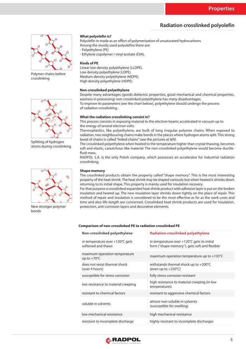
Polymer chains beforecrosslinking
Splitting of hydrogenatoms during crosslinking
New stronger polymerbonds
What polyolefin is?Polyolefin in made as an effect of polymerization of unsaturated hydrocarbons.Among the mostly used polyolefins there are:- Polyethylene (PE)- Ethylene copolymer / vinyl acetate (EVA).
Kinds of PELinear low density polyethylene (LLDPE).Low density polyethylene (LDPE).Medium density polyethylene (MDPE).High density polyethylene (HDPE).
Non-crosslinked polyethyleneDespite many advantages (goods dielectric properties, good mechanical and chemical properties,easiness in processing) non-crosslinked polyethylene has many disadvantages.To improve its parameters (see the chart below), polyethylene should undergo the processof radiation crosslinking.
What the radiation crosslinking consist in?This process consists in exposing material to the electron beams accelerated in vacuum up tothe energy of several electron volts.Thermoplastics, like polyethylene, are built of long irregular polymer chains. When exposed toradiation, two neighbouring chains make bonds in the places where hydrogen atoms split. This strongbond of chains is called “linked chains” (see the pictures at left).The crosslinked polyethylene when heated to the temperature higher than crystal thawing, becomessoft and elastic, caoutchouc-like material. The non-crosslinked polyethylene would become ductile-fluid mass.RADPOL S.A. is the only Polish company, which possesses an accelerator for industrial radiationcrosslinking.
Shape memoryThe crosslinked products obtain the property called “shape memory”. This is the most interestingproperty of the heat shrink. The heat shrink may be shaped variously but when heated it shrinks downreturning to its initial shape. This property is mainly used for insulation recovery.For that purpose a crosslinked expanded heat shrink product with adhesive layer is put on the brokeninsulation and heated up. The new insulation layer shrinks down tightly on the place of repair. Thismethod of repair and insulation is considered to be the most effective as far as the work costs andtime and also life-length are concerned. Crosslinked heat shrink products are used for insulation,protection, anti-corrosion layers and decorative elements.
Non-crosslinked polyethylene Radiation crosslinked polyethylene
in temperature over +120°C getssoftened and thaws
in temperature over +120°C gets its initialform (“shape memory”), gets soft and flexible
maximum operation temperatureup to +70°C maximum operation temperature up to +135°C
does not resist thermal shock(over 4 hours)
withstands thermal shock up to +200°C(even up to +250°C)
susceptible for stress corrosion fully stress corrosion resistant
low resistance to material creeping high resistance to material creeping (in lowtemperatures)
resistant to chemical factors resistant to aggressive chemical factors
soluble in solvents almost non-soluble in solvents(susceptible for swelling)
low mechanical resistance high mechanical resistance
resistant to incomplete discharge highly resistant to incomplete discharges
Comparison of non-crosslinked PE to radiation crosslinked PE
6
Installation manuals
Installation manuals
The installation of heat shrink products produced by RADPOL is quick and easy. In order to reachmaximum satisfaction from the heat shrink products it is suggested to follow the instructions below.
ToolsThe heat shrink products should be shrunk with hot-air blowers, gas heating torches and otherequipment able to reach the temperature of over +120°C.
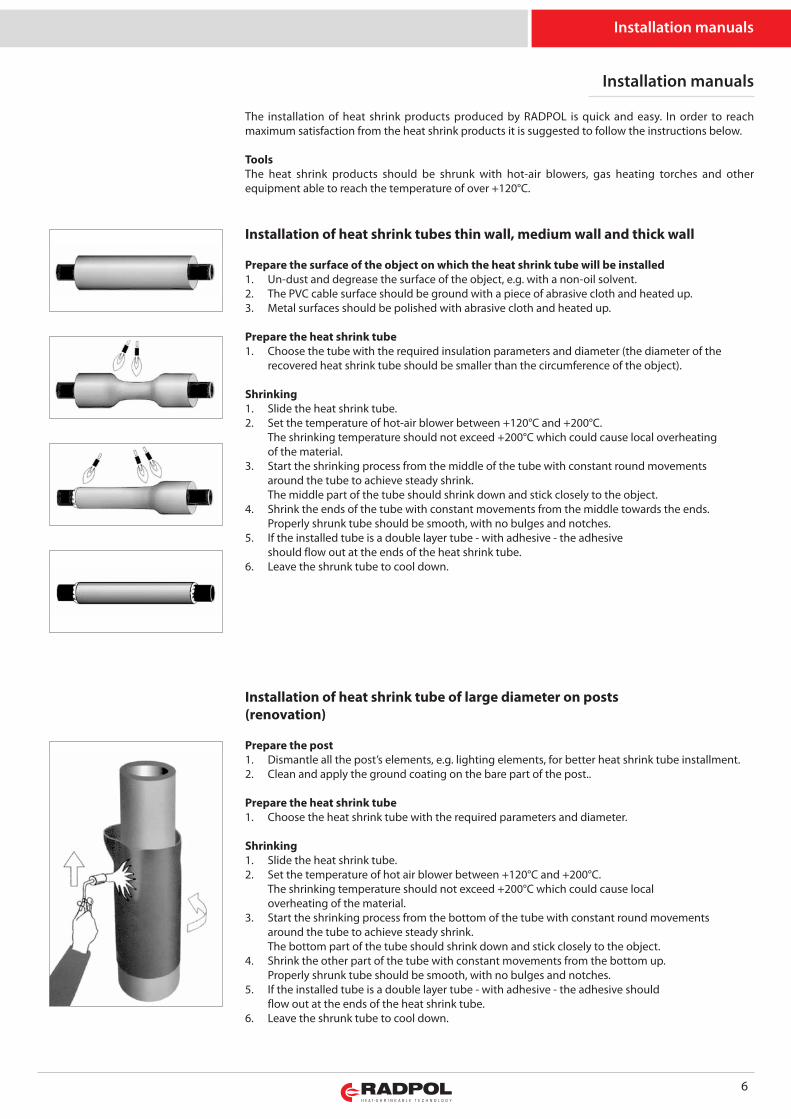
Installation of heat shrink tubes thin wall, medium wall and thick wall
Prepare the surface of the object on which the heat shrink tube will be installed1. Un-dust and degrease the surface of the object, e.g. with a non-oil solvent.2. The PVC cable surface should be ground with a piece of abrasive cloth and heated up.3. Metal surfaces should be polished with abrasive cloth and heated up.
Prepare the heat shrink tube1. Choose the tube with the required insulation parameters and diameter (the diameter of the
recovered heat shrink tube should be smaller than the circumference of the object).
Shrinking1. Slide the heat shrink tube.2. Set the temperature of hot-air blower between +120°C and +200°C.
The shrinking temperature should not exceed +200°C which could cause local overheatingof the material.
3. Start the shrinking process from the middle of the tube with constant round movementsaround the tube to achieve steady shrink.The middle part of the tube should shrink down and stick closely to the object.
4. Shrink the ends of the tube with constant movements from the middle towards the ends.Properly shrunk tube should be smooth, with no bulges and notches.
5. If the installed tube is a double layer tube - with adhesive - the adhesiveshould flow out at the ends of the heat shrink tube.
6. Leave the shrunk tube to cool down.
Installation of heat shrink tube of large diameter on posts(renovation)
Prepare the post1. Dismantle all the post’s elements, e.g. lighting elements, for better heat shrink tube installment.2. Clean and apply the ground coating on the bare part of the post..
Prepare the heat shrink tube1. Choose the heat shrink tube with the required parameters and diameter.
Shrinking1. Slide the heat shrink tube.2. Set the temperature of hot air blower between +120°C and +200°C.
The shrinking temperature should not exceed +200°C which could cause localoverheating of the material.
3. Start the shrinking process from the bottom of the tube with constant round movementsaround the tube to achieve steady shrink.The bottom part of the tube should shrink down and stick closely to the object.
4. Shrink the other part of the tube with constant movements from the bottom up.Properly shrunk tube should be smooth, with no bulges and notches.
5. If the installed tube is a double layer tube - with adhesive - the adhesive shouldflow out at the ends of the heat shrink tube.
6. Leave the shrunk tube to cool down.
7
Installation manuals
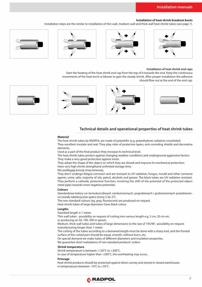
Installation of heat shrink breakout bootsInstallation steps are the similar to installation of thin wall, medium wall and thick wall heat shrink tubes (see page 7).
MaterialThe heat shrink tubes by RADPOL are made of polyolefin (e.g. polyethylene) radiation crosslinked.They excellent insulate and seal. They play roles of protective layers, anti-corroding shields and decorativeelements.Used as a part of the final product they increase its technical level.The heat shrink tubes protect against changing weather conditions and underground aggressive factors. They make a very good protection against moist.They adopt the shape of the object on which they are shrank and improve its mechanical protection.Have very high shrink strengthand unlimited storage time. Nie pod le ga ją ko ro zji zmę cze nio wej.They don't undergo fatigue corrosion and are resistant to UV radiation, fungus, mould and other corrosiveagents; urine, salts, majority of oils, petrol, alcohols and grease. The black tubes are UV radiation resistant.They perform a cathodic protection function, involving the shift of the potential of the protected object(steel pipe) towards more negative potentials.
ColoursStan dar do we ko lo ry rur ter mo kurcz li wych cien ko ścien nych, po gru bio nych i gru bo ścien nych przed sta wio -ne zo sta ły ta be la rycz nie (patrz stro ny 5 do 27).The non-standard colours (eg. gray, fluorescent) are produced on request.Heat shrink tubes of large diameters have black colour.
LengthsStandard length is 1 meter.Thin wall tubes - possibility on request of cutting into various length e.g. 2 cm, 20 cm etc.or producing on 50, 100, 300 m spools.Medium, thick wall tubes and tubes of large dimensions to the size of 195/90 - possibility on requestmanufacturing longer than 1 meter.The cutting of the tubes according to a demaned length must be done with a sharp tool, and the frontialsurface of the cutted part should be equal, smooth, without burrs, etc.On special demand we make tubes of different diameters and insulation properties.We guarantee short realizations of non standard products' orders.
Shrink temperatureShrink temperature is between +120°C to +200°C.In case of temperature higher than +200°C, the overheating may occur..
PrtorageHeat shrink products should be protected against direct sunray and stored in closed warehousesin temperatures between -10°C to +35°C.
Installation of heat shrink end capsStart the heating of the heat shrink end cap from the top of it towards the end. Keep the continuous
movements of the heat torch or blower to gain the steady shrink. After proper installation the adhesiveshould flow out at the end of the end cap.
Technical details and operational properties of heat shrink tubes
8
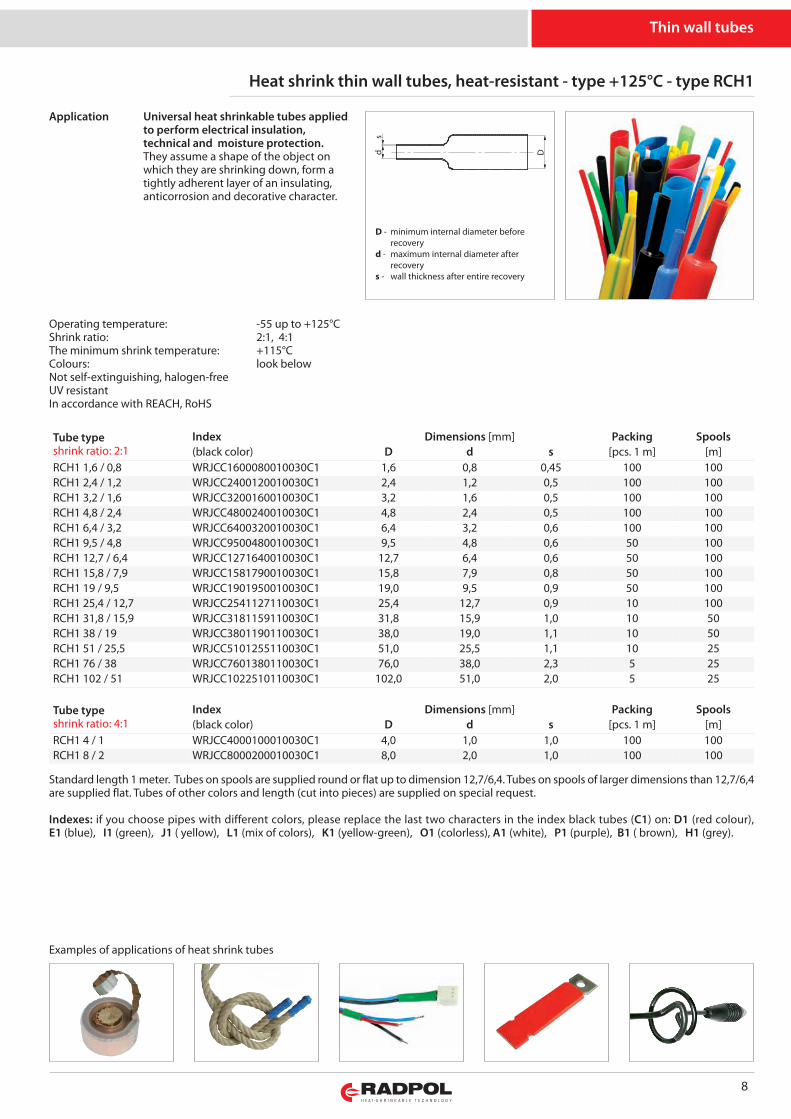
Heat shrink thin wall tubes, heat-resistant - type +125°C - type RCH1
s
Dd
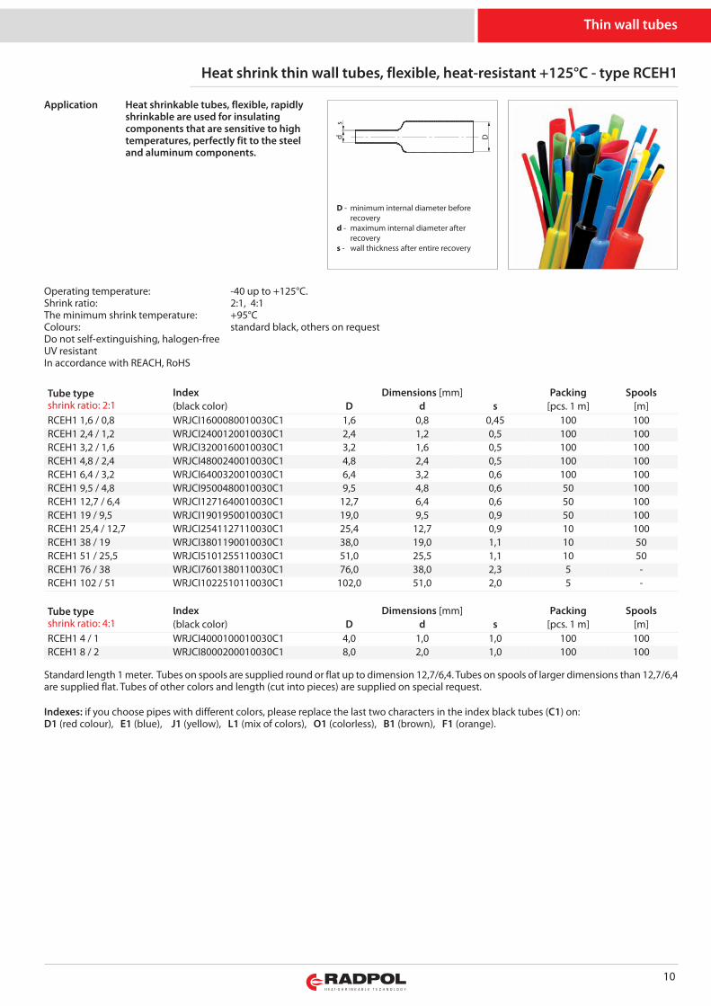
Examples of applications of heat shrink tubes
Standard length 1 meter. Tubes on spools are supplied round or flat up to dimension 12,7/6,4. Tubes on spools of larger dimensions than 12,7/6,4are supplied flat. Tubes of other colors and length (cut into pieces) are supplied on special request.
Indexes: if you choose pipes with different colors, please replace the last two characters in the index black tubes (C1) on: D1 (red colour),E1 (blue), I1 (green), J1 ( yellow), L1 (mix of colors), K1 (yellow-green), O1 (colorless), A1 (white), P1 (purple), B1 ( brown), H1 (grey).
Universal heat shrinkable tubes appliedto perform electrical insulation,technical and moisture protection.They assume a shape of the object onwhich they are shrinking down, form atightly adherent layer of an insulating,anticorrosion and decorative character.
Thin wall tubes
Application
Operating temperature: -55 up to +125°CShrink ratio: 2:1, 4:1The minimum shrink temperature: +115°CColours: look belowNot self-extinguishing, halogen-freeUV resistantIn accordance with REACH, RoHS
Tube typeshrink ratio: 2:1
Index Dimensions [mm] Packing Spools(black color) D d s [pcs. 1 m] [m]
RCH1 1,6 / 0,8 WRJCC1600080010030C1 1,6 0,8 0,45 100 100RCH1 2,4 / 1,2 WRJCC2400120010030C1 2,4 1,2 0,5 100 100RCH1 3,2 / 1,6 WRJCC3200160010030C1 3,2 1,6 0,5 100 100RCH1 4,8 / 2,4 WRJCC4800240010030C1 4,8 2,4 0,5 100 100RCH1 6,4 / 3,2 WRJCC6400320010030C1 6,4 3,2 0,6 100 100RCH1 9,5 / 4,8 WRJCC9500480010030C1 9,5 4,8 0,6 50 100RCH1 12,7 / 6,4 WRJCC1271640010030C1 12,7 6,4 0,6 50 100RCH1 15,8 / 7,9 WRJCC1581790010030C1 15,8 7,9 0,8 50 100RCH1 19 / 9,5 WRJCC1901950010030C1 19,0 9,5 0,9 50 100RCH1 25,4 / 12,7 WRJCC2541127110030C1 25,4 12,7 0,9 10 100RCH1 31,8 / 15,9 WRJCC3181159110030C1 31,8 15,9 1,0 10 50RCH1 38 / 19 WRJCC3801190110030C1 38,0 19,0 1,1 10 50RCH1 51 / 25,5 WRJCC5101255110030C1 51,0 25,5 1,1 10 25RCH1 76 / 38 WRJCC7601380110030C1 76,0 38,0 2,3 5 25RCH1 102 / 51 WRJCC1022510110030C1 102,0 51,0 2,0 5 25
Tube typeshrink ratio: 4:1
Index Dimensions [mm] Packing Spools(black color) D d s [pcs. 1 m] [m]
RCH1 4 / 1 WRJCC4000100010030C1 4,0 1,0 1,0 100 100RCH1 8 / 2 WRJCC8000200010030C1 8,0 2,0 1,0 100 100
D - minimum internal diameter before recoveryd - maximum internal diameter after recoverys - wall thickness after entire recovery

Properties Test method Tubes RCH1Operating temperature -55 up to +125°CLength change after shrinking EN 60684-2 +5 ÷ -10%Tensile strength, min. EN 60684-2 15MPaElongation at rupture, min. EN 60684-2 350%Heat ageing 168 hours EN 60684-2 158°CTensile strength after heat ageing, min. EN 60684-2 12MPaElongation at rupture after heat ageing, min. EN 60684-2 250%
Heat shock (4 hours, temperature) EN 60684-2175°C
no dripping,breaking and wall spreading
Contact with Cu after heat ageing (168 hours, temperature):elongation at rupture, min. EN 60684-2 158°C: 100%
Cu corrosion EN 60684-2 doesn't corrodeCold bend; 4 hours EN 60684-2 doesn't break in temp. -55°CFlammability EN 60684-2 firearmsWater absorptivity, max ISO 62 0,1%Dielectric resistance, min. EN 60684-2; IEC 60243-1 16kV/mmVolume resistivity, min. EN 60684-2; IEC 60093 1012Ωm
9
Thin wall tubes
10
Heat shrink thin wall tubes, flexible, heat-resistant +125°C - type RCEH1
Tube typeshrink ratio: 2:1
Index Dimensions [mm] Packing Spools(black color) D d s [pcs. 1 m] [m]
RCEH1 1,6 / 0,8 WRJCI1600080010030C1 1,6 0,8 0,45 100 100RCEH1 2,4 / 1,2 WRJCI2400120010030C1 2,4 1,2 0,5 100 100RCEH1 3,2 / 1,6 WRJCI3200160010030C1 3,2 1,6 0,5 100 100RCEH1 4,8 / 2,4 WRJCI4800240010030C1 4,8 2,4 0,5 100 100RCEH1 6,4 / 3,2 WRJCI6400320010030C1 6,4 3,2 0,6 100 100RCEH1 9,5 / 4,8 WRJCI9500480010030C1 9,5 4,8 0,6 50 100RCEH1 12,7 / 6,4 WRJCI1271640010030C1 12,7 6,4 0,6 50 100RCEH1 19 / 9,5 WRJCI1901950010030C1 19,0 9,5 0,9 50 100RCEH1 25,4 / 12,7 WRJCI2541127110030C1 25,4 12,7 0,9 10 100RCEH1 38 / 19 WRJCI3801190010030C1 38,0 19,0 1,1 10 50RCEH1 51 / 25,5 WRJCI5101255110030C1 51,0 25,5 1,1 10 50RCEH1 76 / 38 WRJCI7601380110030C1 76,0 38,0 2,3 5 -RCEH1 102 / 51 WRJCI1022510110030C1 102,0 51,0 2,0 5 -
Tube typeshrink ratio: 4:1
Index Dimensions [mm] Packing Spools(black color) D d s [pcs. 1 m] [m]
RCEH1 4 / 1 WRJCI4000100010030C1 4,0 1,0 1,0 100 100RCEH1 8 / 2 WRJCI8000200010030C1 8,0 2,0 1,0 100 100
Heat shrinkable tubes, flexible, rapidlyshrinkable are used for insulatingcomponents that are sensitive to hightemperatures, perfectly fit to the steeland aluminum components.
Application
Standard length 1 meter. Tubes on spools are supplied round or flat up to dimension 12,7/6,4. Tubes on spools of larger dimensions than 12,7/6,4are supplied flat. Tubes of other colors and length (cut into pieces) are supplied on special request.
Indexes: if you choose pipes with different colors, please replace the last two characters in the index black tubes (C1) on:D1 (red colour), E1 (blue), J1 (yellow), L1 (mix of colors), O1 (colorless), B1 (brown), F1 (orange).
Thin wall tubes
Operating temperature: -40 up to +125°C.Shrink ratio: 2:1, 4:1The minimum shrink temperature: +95°CColours: standard black, others on requestDo not self-extinguishing, halogen-freeUV resistantIn accordance with REACH, RoHS
s
Dd
D - minimum internal diameter before recoveryd - maximum internal diameter after recoverys - wall thickness after entire recovery
11
Properties Test method Tubes RCEH1Operating temperature -40 up to +125°CLength change after shrinking EN 60684-2 +5 ÷ -10%Tensile strength, min. EN 60684-2 15 MPaElongation at rupture, min. EN 60684-2 450%Heat ageing 168 hours EN 60684-2 158°CTensile strength after heat ageing, min. EN 60684-2 13 MPaElongation at rupture after heat ageing, min. EN 60684-2 300%
Heat shock (4 hours, temperature) EN 60684-2 200°Cno dripping, breaking and wall spreading
Contact with Cu after heat ageing (168 hours, temperature):elongation at rupture, min. EN 60684-2 158°C
100%
Cu corrosion EN 60684-2 doesn't corrodeCold bend; 4 hours EN 60684-2 doesn't break in temp. -40°CFlammability EN 60684-2 firearmsWater absorptivity, max ISO 62 0,1%Dielectric resistance, min. EN 60684-2; IEC 60243-1 20kV/mmVolume resistivity, min. EN 60684-2; IEC 60093 1012Ωm
Thin wall tubes
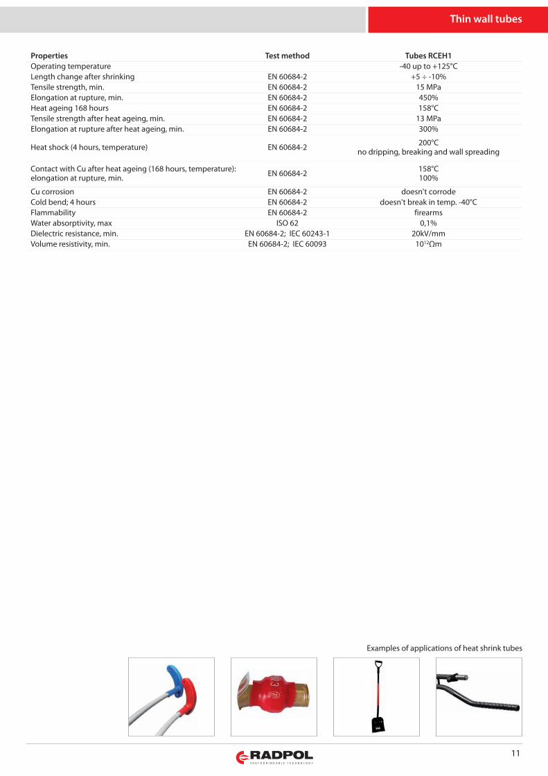
Examples of applications of heat shrink tubes
12
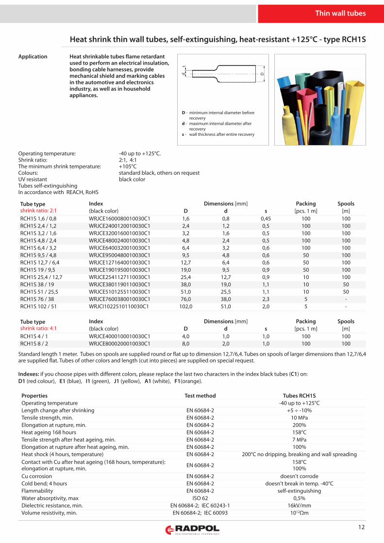
Heat shrink thin wall tubes, self-extinguishing, heat-resistant +125°C - type RCH1S
Tube typeshrink ratio: 2:1
Index Dimensions [mm] Packing Spools(black color) D d s [pcs. 1 m] [m]
RCH1S 1,6 / 0,8 WRJCE1600080010030C1 1,6 0,8 0,45 100 100RCH1S 2,4 / 1,2 WRJCE2400120010030C1 2,4 1,2 0,5 100 100RCH1S 3,2 / 1,6 WRJCE3200160010030C1 3,2 1,6 0,5 100 100RCH1S 4,8 / 2,4 WRJCE4800240010030C1 4,8 2,4 0,5 100 100RCH1S 6,4 / 3,2 WRJCE6400320010030C1 6,4 3,2 0,6 100 100RCH1S 9,5 / 4,8 WRJCE9500480010030C1 9,5 4,8 0,6 50 100RCH1S 12,7 / 6,4 WRJCE1271640010030C1 12,7 6,4 0,6 50 100RCH1S 19 / 9,5 WRJCE1901950010030C1 19,0 9,5 0,9 50 100RCH1S 25,4 / 12,7 WRJCE2541127110030C1 25,4 12,7 0,9 10 100RCH1S 38 / 19 WRJCE3801190110030C1 38,0 19,0 1,1 10 50RCH1S 51 / 25,5 WRJCE5101255110030C1 51,0 25,5 1,1 10 50RCH1S 76 / 38 WRJCE7600380010030C1 76,0 38,0 2,3 5 -RCH1S 102 / 51 WRJCI1022510110030C1 102,0 51,0 2,0 5 -
Tube typeshrink ratio: 4:1
Index Dimensions [mm] Packing Spools(black color) D d s [pcs. 1 m] [m]
RCH1S 4 / 1 WRJCE4000100010030C1 4,0 1,0 1,0 100 100RCH1S 8 / 2 WRJCE8000200010030C1 8,0 2,0 1,0 100 100
Standard length 1 meter. Tubes on spools are supplied round or flat up to dimension 12,7/6,4. Tubes on spools of larger dimensions than 12,7/6,4are supplied flat. Tubes of other colors and length (cut into pieces) are supplied on special request.
Indexes: if you choose pipes with different colors, please replace the last two characters in the index black tubes (C1) on:D1 (red colour), E1 (blue), I1 (green), J1 (yellow), A1 (white), F1(orange).
Thin wall tubes
Operating temperature: -40 up to +125°C.Shrink ratio: 2:1, 4:1The minimum shrink temperature: +105°CColours: standard black, others on requestUV resistant black colorTubes self-extinguishingIn accordance with REACH, RoHS
Heat shrinkable tubes flame retardantused to perform an electrical insulation,bonding cable harnesses, providemechanical shield and marking cablesin the automotive and electronicsindustry, as well as in householdappliances.
Application
s
Dd
D - minimum internal diameter before recoveryd - maximum internal diameter after recoverys - wall thickness after entire recovery
Properties Test method Tubes RCH1SOperating temperature -40 up to +125°CLength change after shrinking EN 60684-2 +5 ÷ -10%Tensile strength, min. EN 60684-2 10 MPaElongation at rupture, min. EN 60684-2 200%Heat ageing 168 hours EN 60684-2 158°CTensile strength after heat ageing, min. EN 60684-2 7 MPaElongation at rupture after heat ageing, min. EN 60684-2 100%Heat shock (4 hours, temperature) EN 60684-2 200°C no dripping, breaking and wall spreadingContact with Cu after heat ageing (168 hours, temperature):elongation at rupture, min. EN 60684-2 158°C
100%Cu corrosion EN 60684-2 doesn't corrodeCold bend; 4 hours EN 60684-2 doesn't break in temp. -40°CFlammability EN 60684-2 self-extinguishingWater absorptivity, max ISO 62 0,5%Dielectric resistance, min. EN 60684-2; IEC 60243-1 16kV/mmVolume resistivity, min. EN 60684-2; IEC 60093 1012Ωm
13
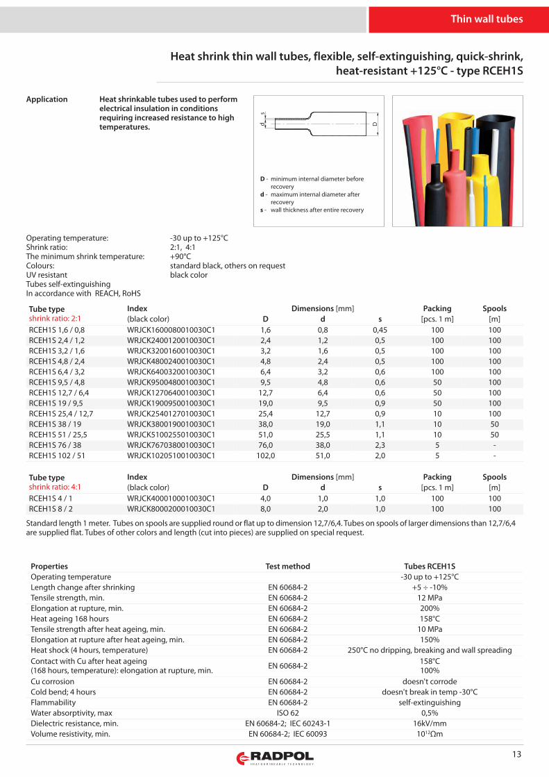
Heat shrink thin wall tubes, flexible, self-extinguishing, quick-shrink,heat-resistant +125°C - type RCEH1S
Tube typeshrink ratio: 2:1
Index Dimensions [mm] Packing Spools(black color) D d s [pcs. 1 m] [m]
RCEH1S 1,6 / 0,8 WRJCK1600080010030C1 1,6 0,8 0,45 100 100RCEH1S 2,4 / 1,2 WRJCK2400120010030C1 2,4 1,2 0,5 100 100RCEH1S 3,2 / 1,6 WRJCK3200160010030C1 3,2 1,6 0,5 100 100RCEH1S 4,8 / 2,4 WRJCK4800240010030C1 4,8 2,4 0,5 100 100RCEH1S 6,4 / 3,2 WRJCK6400320010030C1 6,4 3,2 0,6 100 100RCEH1S 9,5 / 4,8 WRJCK9500480010030C1 9,5 4,8 0,6 50 100RCEH1S 12,7 / 6,4 WRJCK1270640010030C1 12,7 6,4 0,6 50 100RCEH1S 19 / 9,5 WRJCK1900950010030C1 19,0 9,5 0,9 50 100RCEH1S 25,4 / 12,7 WRJCK2540127010030C1 25,4 12,7 0,9 10 100RCEH1S 38 / 19 WRJCK3800190010030C1 38,0 19,0 1,1 10 50RCEH1S 51 / 25,5 WRJCK5100255010030C1 51,0 25,5 1,1 10 50RCEH1S 76 / 38 WRJCK7670380010030C1 76,0 38,0 2,3 5 -RCEH1S 102 / 51 WRJCK1020510010030C1 102,0 51,0 2,0 5 -
Tube typeshrink ratio: 4:1
Index Dimensions [mm] Packing Spools(black color) D d s [pcs. 1 m] [m]
RCEH1S 4 / 1 WRJCK4000100010030C1 4,0 1,0 1,0 100 100RCEH1S 8 / 2 WRJCK8000200010030C1 8,0 2,0 1,0 100 100
Standard length 1 meter. Tubes on spools are supplied round or flat up to dimension 12,7/6,4. Tubes on spools of larger dimensions than 12,7/6,4are supplied flat. Tubes of other colors and length (cut into pieces) are supplied on special request.
Thin wall tubes
Operating temperature: -30 up to +125°CShrink ratio: 2:1, 4:1The minimum shrink temperature: +90°CColours: standard black, others on requestUV resistant black colorTubes self-extinguishingIn accordance with REACH, RoHS
Heat shrinkable tubes used to performelectrical insulation in conditionsrequiring increased resistance to hightemperatures.
Application
s
Dd
D - minimum internal diameter before recoveryd - maximum internal diameter after recoverys - wall thickness after entire recovery
Properties Test method Tubes RCEH1SOperating temperature -30 up to +125°CLength change after shrinking EN 60684-2 +5 ÷ -10%Tensile strength, min. EN 60684-2 12 MPaElongation at rupture, min. EN 60684-2 200%Heat ageing 168 hours EN 60684-2 158°CTensile strength after heat ageing, min. EN 60684-2 10 MPaElongation at rupture after heat ageing, min. EN 60684-2 150%Heat shock (4 hours, temperature) EN 60684-2 250°C no dripping, breaking and wall spreadingContact with Cu after heat ageing(168 hours, temperature): elongation at rupture, min. EN 60684-2 158°C
100%Cu corrosion EN 60684-2 doesn't corrodeCold bend; 4 hours EN 60684-2 doesn't break in temp -30°CFlammability EN 60684-2 self-extinguishingWater absorptivity, max ISO 62 0,5%Dielectric resistance, min. EN 60684-2; IEC 60243-1 16kV/mmVolume resistivity, min. EN 60684-2; IEC 60093 1012Ωm
14
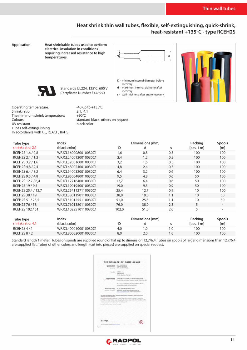
Heat shrink thin wall tubes, flexible, self-extinguishing, quick-shrink,heat-resistant +135°C - type RCEH2S
Standard length 1 meter. Tubes on spools are supplied round or flat up to dimension 12,7/6,4. Tubes on spools of larger dimensions than 12,7/6,4are supplied flat. Tubes of other colors and length (cut into pieces) are supplied on special request.
Thin wall tubes
Heat shrinkable tubes used to performelectrical insulation in conditionsrequiring increased resistance to hightemperatures.
Application
s
Dd
D - minimum internal diameter before recoveryd - maximum internal diameter after recoverys - wall thickness after entire recovery
Tube typeshrink ratio: 2:1
Index Dimensions [mm] Packing Spools(black color) D d s [pcs. 1 m] [m]
RCEH2S 1,6 / 0,8 WRJCL1600080010030C1 1,6 0,8 0,5 100 100RCEH2S 2,4 / 1,2 WRJCL2400120010030C1 2,4 1,2 0,5 100 100RCEH2S 3,2 / 1,6 WRJCL3200160010030C1 3,2 1,6 0,5 100 100RCEH2S 4,8 / 2,4 WRJCL4800240010030C1 4,8 2,4 0,5 100 100RCEH2S 6,4 / 3,2 WRJCL6400320010030C1 6,4 3,2 0,6 100 100RCEH2S 9,5 / 4,8 WRJCL9500480010030C1 9,5 4,8 0,6 50 100RCEH2S 12,7 / 6,4 WRJCL1271640010030C1 12,7 6,4 0,6 50 100RCEH2S 19 / 9,5 WRJCL1901950010030C1 19,0 9,5 0,9 50 100RCEH2S 25,4 / 12,7 WRJCL2541127110030C1 25,4 12,7 0,9 10 100RCEH2S 38 / 19 WRJCL3801190110030C1 38,0 19,0 1,1 10 50RCEH2S 51 / 25,5 WRJCL5101255110030C1 51,0 25,5 1,1 10 50RCEH2S 76 / 38 WRJCL7601380110030C1 76,0 38,0 2,3 5 -RCEH2S 102 / 51 WRJCL1022510110030C1 102,0 51,0 2,0 5 -
Tube typeshrink ratio: 4:1
Index Dimensions [mm] Packing Spools(black color) D d s [pcs. 1 m] [m]
RCEH2S 4 / 1 WRJCL4000100010030C1 4,0 1,0 1,0 100 100RCEH2S 8 / 2 WRJCL8000200010030C1 8,0 2,0 1,0 100 100
Operating temperature: -40 up to +135°CShrink ratio: 2:1, 4:1The minimum shrink temperature: +90°CColours: standard black, others on requestUV resistant black colorTubes self-extinguishingIn accordance with UL, REACH, RoHS
Standards UL224, 125°C, 600 VCertyficate Number E478953

15
Thin wall tubes
Properties Test methodUL224, EN 60684-2 Tubes RCEH2S
Operating temperature -40 up to +135°CRated voltage UL 224 600 VLength change after shrinking UL 224 ±3%Tensile strength, min. UL 224 min. 10,4 MPaElongation at rupture, min. UL 224 min. 200%Secant module at elongation UL 224 max. 175%Heat shock (4 hours, temperature 250°C) UL 224 no dripping, breaking and wall spreadingHeat ageing 168 hours EN 60684-2 168 h, temperature 175°CTensile strength after heat ageing UL 224 min. 7,3 MPaElongation at rupture after heat ageing, min. UL 224 min. 200%Cold bend (4 h, temperature -40°C ) UL 224 doesn't break in temp -40°CCu corrosion (168 h, temperature 158°C) UL 224 doesn't corrodeFlammability (test wszystkie rury) UL 224 self-extinguishing – max 30 secDielectric resistance, min. UL 224 min. 16kV/mmVolume resistivity, min. UL 224 min. 1014Ωcm
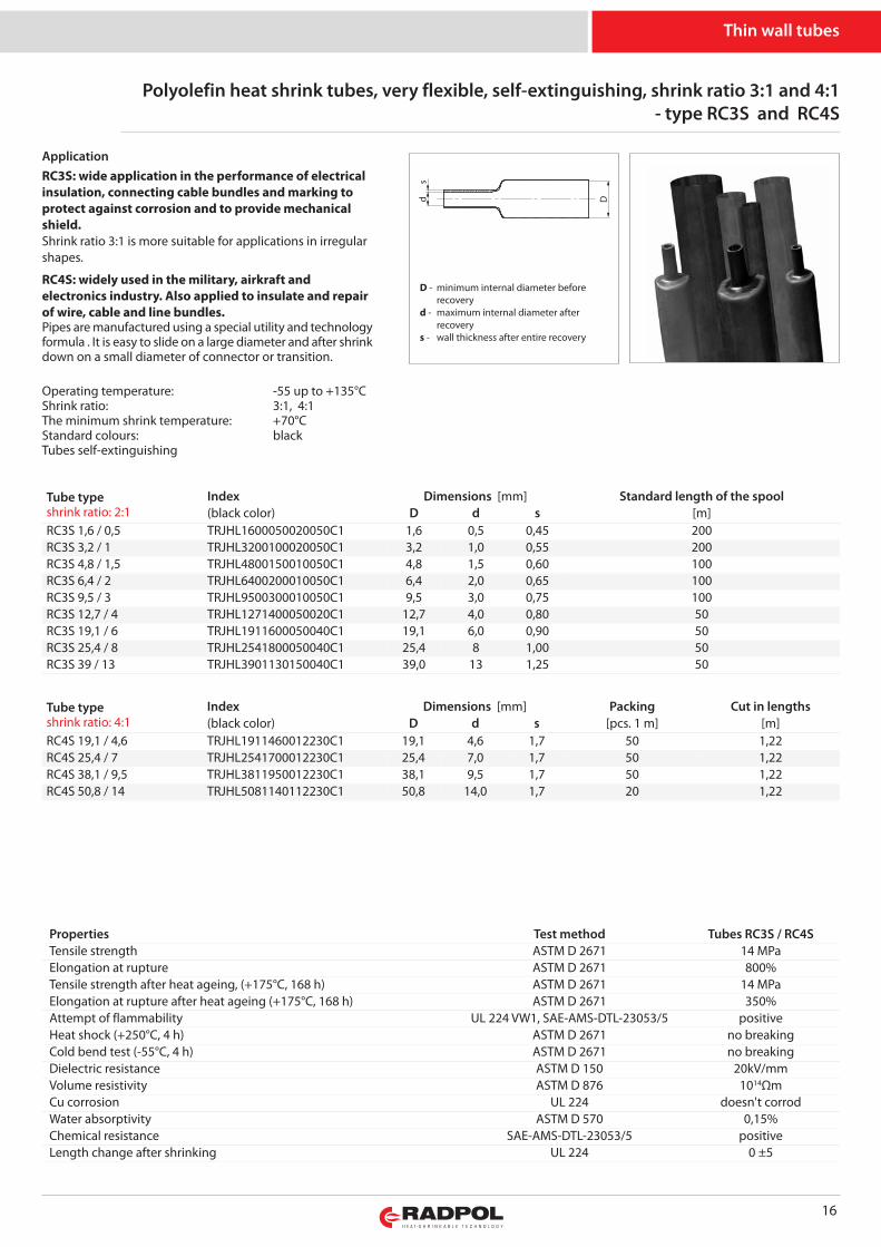
RC3S: wide application in the performance of electricalinsulation, connecting cable bundles and marking toprotect against corrosion and to provide mechanicalshield.Shrink ratio 3:1 is more suitable for applications in irregularshapes.
RC4S: widely used in the military, airkraft andelectronics industry. Also applied to insulate and repairof wire, cable and line bundles.Pipes are manufactured using a special utility and technologyformula . It is easy to slide on a large diameter and after shrinkdown on a small diameter of connector or transition.
16
Tube typeshrink ratio: 2:1
Index Dimensions [mm] Standard length of the spool(black color) D d s [m]
RC3S 1,6 / 0,5 TRJHL1600050020050C1 1,6 0,5 0,45 200RC3S 3,2 / 1 TRJHL3200100020050C1 3,2 1,0 0,55 200RC3S 4,8 / 1,5 TRJHL4800150010050C1 4,8 1,5 0,60 100RC3S 6,4 / 2 TRJHL6400200010050C1 6,4 2,0 0,65 100RC3S 9,5 / 3 TRJHL9500300010050C1 9,5 3,0 0,75 100RC3S 12,7 / 4 TRJHL1271400050020C1 12,7 4,0 0,80 50RC3S 19,1 / 6 TRJHL1911600050040C1 19,1 6,0 0,90 50RC3S 25,4 / 8 TRJHL2541800050040C1 25,4 8 1,00 50RC3S 39 / 13 TRJHL3901130150040C1 39,0 13 1,25 50
Tube typeshrink ratio: 4:1
Index Dimensions [mm] Packing Cut in lengths(black color) D d s [pcs. 1 m] [m]
RC4S 19,1 / 4,6 TRJHL1911460012230C1 19,1 4,6 1,7 50 1,22RC4S 25,4 / 7 TRJHL2541700012230C1 25,4 7,0 1,7 50 1,22RC4S 38,1 / 9,5 TRJHL3811950012230C1 38,1 9,5 1,7 50 1,22RC4S 50,8 / 14 TRJHL5081140112230C1 50,8 14,0 1,7 20 1,22
Properties Test method Tubes RC3S / RC4STensile strength ASTM D 2671 14 MPaElongation at rupture ASTM D 2671 800%Tensile strength after heat ageing, (+175°C, 168 h) ASTM D 2671 14 MPaElongation at rupture after heat ageing (+175°C, 168 h) ASTM D 2671 350%Attempt of flammability UL 224 VW1, SAE-AMS-DTL-23053/5 positiveHeat shock (+250°C, 4 h) ASTM D 2671 no breakingCold bend test (-55°C, 4 h) ASTM D 2671 no breakingDielectric resistance ASTM D 150 20kV/mmVolume resistivity ASTM D 876 1014ΩmCu corrosion UL 224 doesn't corrodWater absorptivity ASTM D 570 0,15%Chemical resistance SAE-AMS-DTL-23053/5 positiveLength change after shrinking UL 224 0 ±5
Polyolefin heat shrink tubes, very flexible, self-extinguishing, shrink ratio 3:1 and 4:1- type RC3S and RC4S
Thin wall tubes
Operating temperature: -55 up to +135°CShrink ratio: 3:1, 4:1The minimum shrink temperature: +70°CStandard colours: blackTubes self-extinguishing
Application
s
Dd
D - minimum internal diameter before recoveryd - maximum internal diameter after recoverys - wall thickness after entire recovery
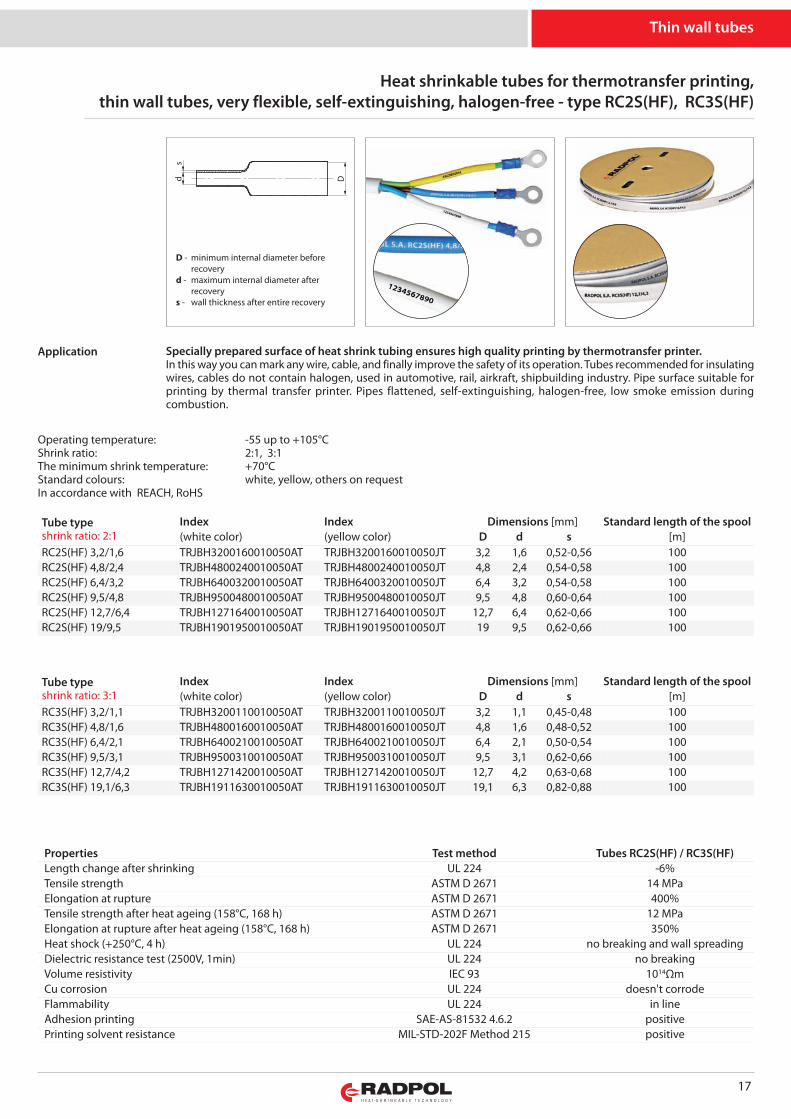
Heat shrinkable tubes for thermotransfer printing, thin wall tubes, very flexible, self-extinguishing, halogen-free - type RC2S(HF), RC3S(HF)
17
Tube typeshrink ratio: 2:1
Index Index Dimensions [mm] Standard length of the spool(white color) (yellow color) D d s [m]
RC2S(HF) 3,2/1,6 TRJBH3200160010050AT TRJBH3200160010050JT 3,2 1,6 0,52-0,56 100RC2S(HF) 4,8/2,4 TRJBH4800240010050AT TRJBH4800240010050JT 4,8 2,4 0,54-0,58 100RC2S(HF) 6,4/3,2 TRJBH6400320010050AT TRJBH6400320010050JT 6,4 3,2 0,54-0,58 100RC2S(HF) 9,5/4,8 TRJBH9500480010050AT TRJBH9500480010050JT 9,5 4,8 0,60-0,64 100RC2S(HF) 12,7/6,4 TRJBH1271640010050AT TRJBH1271640010050JT 12,7 6,4 0,62-0,66 100RC2S(HF) 19/9,5 TRJBH1901950010050AT TRJBH1901950010050JT 19 9,5 0,62-0,66 100
Properties Test method Tubes RC2S(HF) / RC3S(HF)Length change after shrinking UL 224 -6%Tensile strength ASTM D 2671 14 MPaElongation at rupture ASTM D 2671 400%Tensile strength after heat ageing (158°C, 168 h) ASTM D 2671 12 MPaElongation at rupture after heat ageing (158°C, 168 h) ASTM D 2671 350%Heat shock (+250°C, 4 h) UL 224 no breaking and wall spreadingDielectric resistance test (2500V, 1min) UL 224 no breakingVolume resistivity IEC 93 1014ΩmCu corrosion UL 224 doesn't corrodeFlammability UL 224 in lineAdhesion printing SAE-AS-81532 4.6.2 positivePrinting solvent resistance MIL-STD-202F Method 215 positive
Tube typeshrink ratio: 3:1
Index Index Dimensions [mm] Standard length of the spool(white color) (yellow color) D d s [m]
RC3S(HF) 3,2/1,1 TRJBH3200110010050AT TRJBH3200110010050JT 3,2 1,1 0,45-0,48 100RC3S(HF) 4,8/1,6 TRJBH4800160010050AT TRJBH4800160010050JT 4,8 1,6 0,48-0,52 100RC3S(HF) 6,4/2,1 TRJBH6400210010050AT TRJBH6400210010050JT 6,4 2,1 0,50-0,54 100RC3S(HF) 9,5/3,1 TRJBH9500310010050AT TRJBH9500310010050JT 9,5 3,1 0,62-0,66 100RC3S(HF) 12,7/4,2 TRJBH1271420010050AT TRJBH1271420010050JT 12,7 4,2 0,63-0,68 100RC3S(HF) 19,1/6,3 TRJBH1911630010050AT TRJBH1911630010050JT 19,1 6,3 0,82-0,88 100
Thin wall tubes
Specially prepared surface of heat shrink tubing ensures high quality printing by thermotransfer printer.In this way you can mark any wire, cable, and finally improve the safety of its operation. Tubes recommended for insulatingwires, cables do not contain halogen, used in automotive, rail, airkraft, shipbuilding industry. Pipe surface suitable forprinting by thermal transfer printer. Pipes flattened, self-extinguishing, halogen-free, low smoke emission duringcombustion.
Operating temperature: -55 up to +105°CShrink ratio: 2:1, 3:1The minimum shrink temperature: +70°CStandard colours: white, yellow, others on requestIn accordance with REACH, RoHS
Application
s
Dd
D - minimum internal diameter before recoveryd - maximum internal diameter after recoverys - wall thickness after entire recovery
18
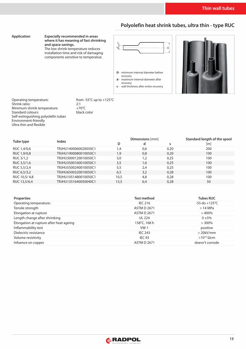
Polyolefin heat shrink tubes, ultra thin - type RUC
Especially recommended in areaswhere it has meaning of fast shrinkingand space savings.The low shrink temperature reducesinstallation time and risk of damagingcomponents sensitive to temperatue.
Properties Test method Tubes RUCOperating temperature: IEC 216 -55 do +125°CTensile strength ASTM D 2671 > 14 MPaElongation at rupture ASTM D 2671 > 400%Length change after shrinking UL 224 0 ±5%Elongation at rupture after heat ageing 158°C, 168 h > 300%Inflammability test VW-1 positiveDielectric resistance IEC 243 > 20kV/mmVolume resistivity IEC 93 >1014 ΩcmInfuence on copper ASTM D 2671 doesn't corrode
Thin wall tubes
Tube type IndexDimensions [mm] Standard length of the spool
D d s [m]RUC 1,4/0,6 TRJHU1400060020050C1 1,4 0,6 0,20 200RUC 1,9/0,8 TRJHU1900080010050C1 1,9 0,8 0,20 100RUC 3/1,2 TRJHU3000120010050C1 3,0 1,2 0,25 100RUC 3,5/1,6 TRJHU3500160010050C1 3,5 1,6 0,25 100RUC 5,5/2,4 TRJHU5500240010050C1 5,5 2,4 0,25 100RUC 6,5/3,2 TRJHU6500320010050C1 6,5 3,2 0,28 100RUC 10,5/ 4,8 TRJHU1051480010050C1 10,5 4,8 0,28 100RUC 13,5/6,4 TRJHU1351640050040C1 13,5 6,4 0,28 50
Operating temperature: from -55°C up to +125°CShrink ratio: 2:1Minimum shrink temperature: +70°CStandard colours: black colorSelf-extinguishing polyolefin tubesEnvironment-friendlyUltra thin and flexible
s
Dd
Application
D - minimum internal diameter before recoveryd - maximum internal diameter after recoverys - wall thickness after entire recovery
19
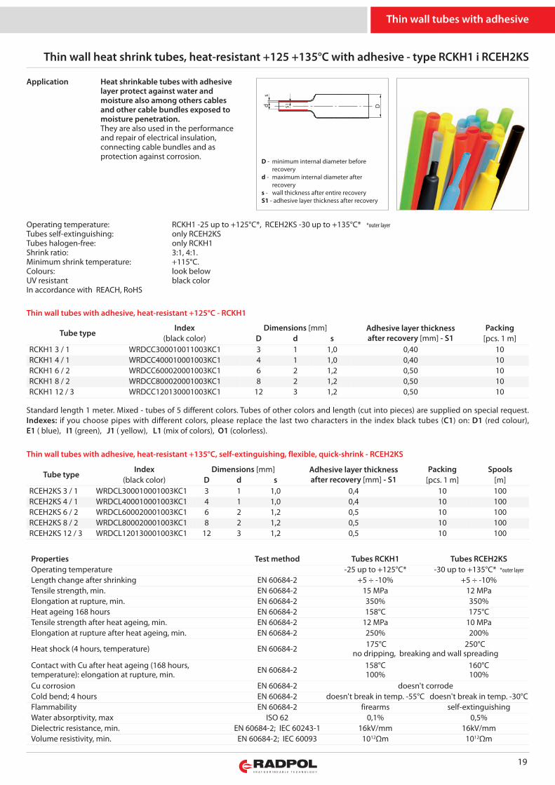
Thin wall heat shrink tubes, heat-resistant +125 +135°C with adhesive - type RCKH1 i RCEH2KS
s
Dd s1
Tube typeIndex Dimensions [mm] Adhesive layer thickness
after recovery [mm] - S1Packing
(black color) D d s [pcs. 1 m]RCKH1 3 / 1 WRDCC300010011003KC1 3 1 1,0 0,40 10RCKH1 4 / 1 WRDCC400010001003KC1 4 1 1,0 0,40 10RCKH1 6 / 2 WRDCC600020001003KC1 6 2 1,2 0,50 10RCKH1 8 / 2 WRDCC800020001003KC1 8 2 1,2 0,50 10RCKH1 12 / 3 WRDCC120130001003KC1 12 3 1,2 0,50 10
Heat shrinkable tubes with adhesivelayer protect against water andmoisture also among others cablesand other cable bundles exposed tomoisture penetration.They are also used in the performanceand repair of electrical insulation,connecting cable bundles and asprotection against corrosion.
Standard length 1 meter. Mixed - tubes of 5 different colors. Tubes of other colors and length (cut into pieces) are supplied on special request.Indexes: if you choose pipes with different colors, please replace the last two characters in the index black tubes (C1) on: D1 (red colour),E1 ( blue), I1 (green), J1 ( yellow), L1 (mix of colors), O1 (colorless).
Thin wall tubes with adhesive, heat-resistant +125°C - RCKH1
Thin wall tubes with adhesive, heat-resistant +135°C, self-extinguishing, flexible, quick-shrink - RCEH2KS
Properties Test method Tubes RCKH1 Tubes RCEH2KSOperating temperature -25 up to +125°C* -30 up to +135°C* *outer layer
Length change after shrinking EN 60684-2 +5 ÷ -10% +5 ÷ -10%Tensile strength, min. EN 60684-2 15 MPa 12 MPaElongation at rupture, min. EN 60684-2 350% 350%Heat ageing 168 hours EN 60684-2 158°C 175°CTensile strength after heat ageing, min. EN 60684-2 12 MPa 10 MPaElongation at rupture after heat ageing, min. EN 60684-2 250% 200%
Heat shock (4 hours, temperature) EN 60684-2 175°C 250°C no dripping, breaking and wall spreading
Contact with Cu after heat ageing (168 hours,temperature): elongation at rupture, min. EN 60684-2 158°C
100%160°C100%
Cu corrosion EN 60684-2 doesn't corrodeCold bend; 4 hours EN 60684-2 doesn't break in temp. -55°C doesn't break in temp. -30°CFlammability EN 60684-2 firearms self-extinguishingWater absorptivity, max ISO 62 0,1% 0,5%Dielectric resistance, min. EN 60684-2; IEC 60243-1 16kV/mm 16kV/mmVolume resistivity, min. EN 60684-2; IEC 60093 1012Ωm 1012Ωm
Tube typeIndex Dimensions [mm] Adhesive layer thickness
after recovery [mm] - S1Packing Spools
(black color) D d s [pcs. 1 m] [m]RCEH2KS 3 / 1 WRDCL300010001003KC1 3 1 1,0 0,4 10 100RCEH2KS 4 / 1 WRDCL400010001003KC1 4 1 1,0 0,4 10 100RCEH2KS 6 / 2 WRDCL600020001003KC1 6 2 1,2 0,5 10 100RCEH2KS 8 / 2 WRDCL800020001003KC1 8 2 1,2 0,5 10 100RCEH2KS 12 / 3 WRDCL120130001003KC1 12 3 1,2 0,5 10 100
Thin wall tubes with adhesive
D - minimum internal diameter before recoveryd - maximum internal diameter after recoverys - wall thickness after entire recoveryS1 - adhesive layer thickness after recovery
Operating temperature: RCKH1 -25 up to +125°C*, RCEH2KS -30 up to +135°C* *outer layerTubes self-extinguishing: only RCEH2KSTubes halogen-free: only RCKH1Shrink ratio: 3:1, 4:1.Minimum shrink temperature: +115°C.Colours: look belowUV resistant black colorIn accordance with REACH, RoHS
Application
20
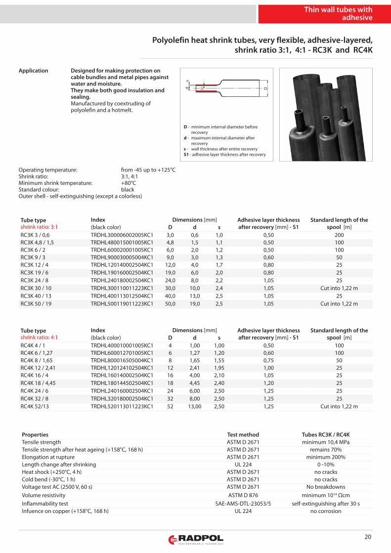
Polyolefin heat shrink tubes, very flexible, adhesive-layered,shrink ratio 3:1, 4:1 - RC3K and RC4K
Properties Test method Tubes RC3K / RC4KTensile strength ASTM D 2671 minimum 10,4 MPaTensile strength after heat ageing (+158°C, 168 h) ASTM D 2671 remains 70%Elongation at rupture ASTM D 2671 minimum 200%Length change after shrinking UL 224 0 -10%Heat shock (+250°C, 4 h) ASTM D 2671 no cracksCold bend (-30°C, 1 h) ASTM D 2671 no cracksVoltage test AC (2500 V, 60 s) ASTM D 2671 No breakdownsVolume resistivity ASTM D 876 minimum 1014 ΩcmInflammability test SAE-AMS-DTL-23053/5 self-extinguishing after 30 sInfuence on copper (+158°C, 168 h) UL 224 no corrosion
Designed for making protection oncable bundles and metal pipes againstwater and moisture.They make both good insulation andsealing.Manufactured by coextruding ofpolyolefin and a hotmelt.
Tube typeshrink ratio: 3:1
Index Dimensions [mm] Adhesive layer thicknessafter recovery [mm] - S1
Standard length of thespool [m](black color) D d s
RC3K 3 / 0,6 TRDHL300006002005KC1 3,0 0,6 1,0 0,50 200RC3K 4,8 / 1,5 TRDHL480015001005KC1 4,8 1,5 1,1 0,50 100RC3K 6 / 2 TRDHL600020001005KC1 6,0 2,0 1,2 0,50 100RC3K 9 / 3 TRDHL900030005004KC1 9,0 3,0 1,3 0,60 50RC3K 12 / 4 TRDHL120140002504KC1 12,0 4,0 1,7 0,80 25RC3K 19 / 6 TRDHL190160002504KC1 19,0 6,0 2,0 0,80 25RC3K 24 / 8 TRDHL240180002504KC1 24,0 8,0 2,2 1,05 25RC3K 30 / 10 TRDHL300110011223KC1 30,0 10,0 2,4 1,05 Cut into 1,22 mRC3K 40 / 13 TRDHL400113012504KC1 40,0 13,0 2,5 1,05 25RC3K 50 / 19 TRDHL500119011223KC1 50,0 19,0 2,5 1,05 Cut into 1,22 m
Tube typeshrink ratio: 4:1
Index Dimensions [mm] Adhesive layer thicknessafter recovery [mm] - S1
Standard length of thespool [m](black color) D d s
RC4K 4 / 1 TRDHL400010001005KC1 4 1,00 1,00 0,50 100RC4K 6 / 1,27 TRDHL600012701005KC1 6 1,27 1,20 0,60 100RC4K 8 / 1,65 TRDHL800016505004KC1 8 1,65 1,55 0,75 50RC4K 12 / 2,41 TRDHL120124102504KC1 12 2,41 1,95 1,00 25RC4K 16 / 4 TRDHL160140002504KC1 16 4,00 2,10 1,05 25RC4K 18 / 4,45 TRDHL180144502504KC1 18 4,45 2,40 1,20 25RC4K 24 / 6 TRDHL240160002504KC1 24 6,00 2,50 1,25 25RC4K 32 / 8 TRDHL320180002504KC1 32 8,00 2,50 1,25 25RC4K 52/13 TRDHL520113011223KC1 52 13,00 2,50 1,25 Cut into 1,22 m
Thin wall tubes withadhesive
Operating temperature: from -45 up to +125°CShrink ratio: 3:1, 4:1Minimum shrink temperature: +80°CStandard colour: blackOuter shell - self-extinguishing (except a colorless)
s
Dd s1
D - minimum internal diameter before recoveryd - maximum internal diameter after recoverys - wall thickness after entire recoveryS1 - adhesive layer thickness after recovery
Application
21
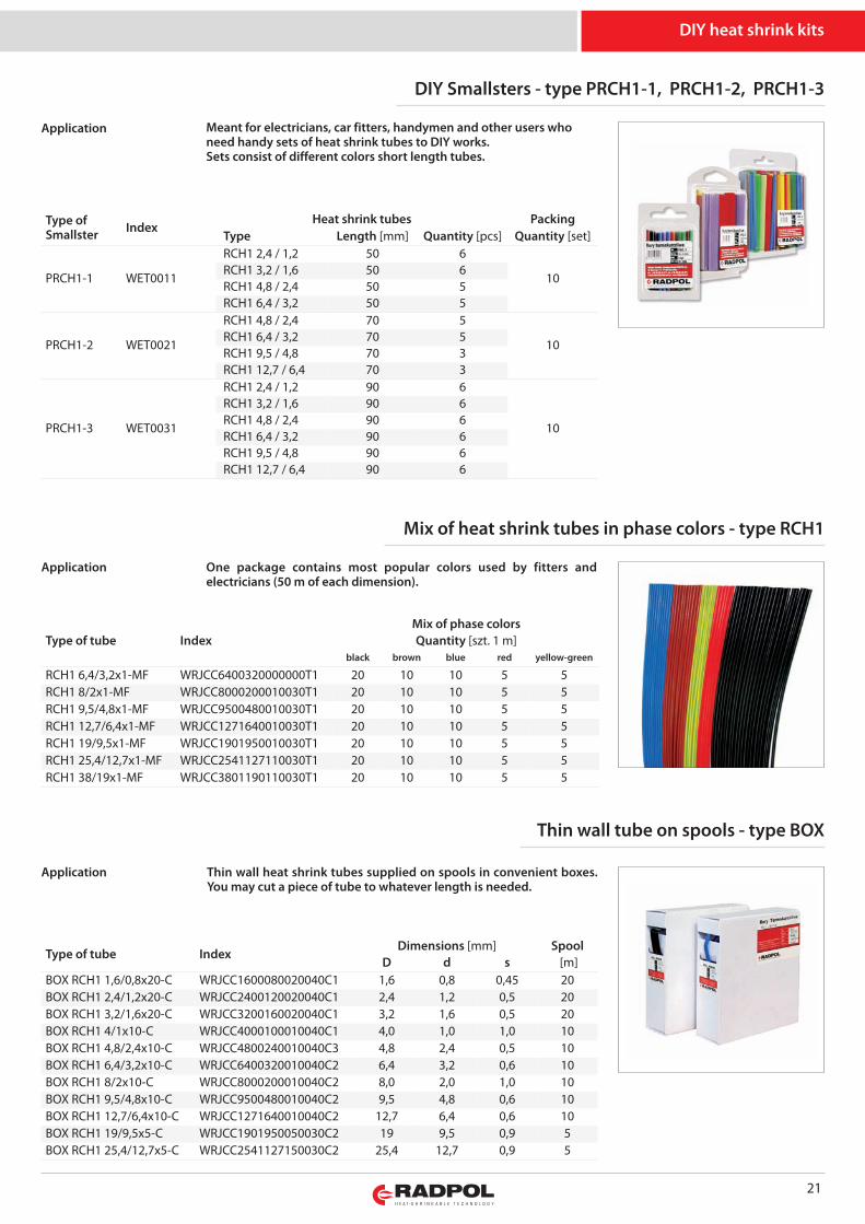
DIY Smallsters - type PRCH1-1, PRCH1-2, PRCH1-3
Type ofSmallster Index
Heat shrink tubes PackingType Length [mm] Quantity [pcs] Quantity [set]
PRCH1-1 WET0011
RCH1 2,4 / 1,2 50 6
10RCH1 3,2 / 1,6 50 6RCH1 4,8 / 2,4 50 5RCH1 6,4 / 3,2 50 5
PRCH1-2 WET0021
RCH1 4,8 / 2,4 70 5
10RCH1 6,4 / 3,2 70 5RCH1 9,5 / 4,8 70 3RCH1 12,7 / 6,4 70 3
PRCH1-3 WET0031
RCH1 2,4 / 1,2 90 6
10
RCH1 3,2 / 1,6 90 6RCH1 4,8 / 2,4 90 6RCH1 6,4 / 3,2 90 6RCH1 9,5 / 4,8 90 6RCH1 12,7 / 6,4 90 6
Mix of heat shrink tubes in phase colors - type RCH1
One package contains most popular colors used by fitters andelectricians (50 m of each dimension).
Type of tube IndexMix of phase colorsQuantity [szt. 1 m]
black brown blue red yellow-green
RCH1 6,4/3,2x1-MF WRJCC6400320000000T1 20 10 10 5 5RCH1 8/2x1-MF WRJCC8000200010030T1 20 10 10 5 5RCH1 9,5/4,8x1-MF WRJCC9500480010030T1 20 10 10 5 5RCH1 12,7/6,4x1-MF WRJCC1271640010030T1 20 10 10 5 5RCH1 19/9,5x1-MF WRJCC1901950010030T1 20 10 10 5 5RCH1 25,4/12,7x1-MF WRJCC2541127110030T1 20 10 10 5 5RCH1 38/19x1-MF WRJCC3801190110030T1 20 10 10 5 5
Type of tube IndexDimensions [mm] Spool
D d s [m]BOX RCH1 1,6/0,8x20-C WRJCC1600080020040C1 1,6 0,8 0,45 20BOX RCH1 2,4/1,2x20-C WRJCC2400120020040C1 2,4 1,2 0,5 20BOX RCH1 3,2/1,6x20-C WRJCC3200160020040C1 3,2 1,6 0,5 20BOX RCH1 4/1x10-C WRJCC4000100010040C1 4,0 1,0 1,0 10BOX RCH1 4,8/2,4x10-C WRJCC4800240010040C3 4,8 2,4 0,5 10BOX RCH1 6,4/3,2x10-C WRJCC6400320010040C2 6,4 3,2 0,6 10BOX RCH1 8/2x10-C WRJCC8000200010040C2 8,0 2,0 1,0 10BOX RCH1 9,5/4,8x10-C WRJCC9500480010040C2 9,5 4,8 0,6 10BOX RCH1 12,7/6,4x10-C WRJCC1271640010040C2 12,7 6,4 0,6 10BOX RCH1 19/9,5x5-C WRJCC1901950050030C2 19 9,5 0,9 5BOX RCH1 25,4/12,7x5-C WRJCC2541127150030C2 25,4 12,7 0,9 5
Thin wall tube on spools - type BOX
Thin wall heat shrink tubes supplied on spools in convenient boxes.You may cut a piece of tube to whatever length is needed.
DIY heat shrink kits
Application Meant for electricians, car fitters, handymen and other users whoneed handy sets of heat shrink tubes to DIY works. Sets consist of different colors short length tubes.
Application
Application
22
Content Typeof element
Set ZDM 1Index WET010
Set ZDM 2Index WET012
Set ZDM 3Index WET014
Length [mm] Quantity [pcs] Length [mm] Quantity [pcs] Length [mm] Quantity [pcs]
Heat shrink tube
RCH1 1,6 / 0,8 - - 55 60 55 30RCH1 2,4 / 1,2 95 60 55 30 55 20RCH1 3,2 / 1,6 95 40 55 25 55 14RCH1 4,8 / 2,4 95 24 55 15 55 10RCH1 6,4 / 3,2 95 14 100 15 100 14RCH1 12,7 / 6,4 95 2 100 8 100 5RCH1 19 / 9,5 95 2 100 3 100 5RCH1 25,4 / 12,7 95 2 - - - -RCH1 2,4 / 1,2 195 3 - - - -RCH1 3,2 / 1,6 195 2 - - - -RCH1 4,8 / 2,4 195 3 - - - -RCH1 6,4 / 3,2 195 2 - - - -RCH1 9,5 / 4,8 195 1 100 8 100 8RCH1 12,7 / 6,4 195 1 - - - -RPH1 12 / 4 - - 100 6 100 4
Copper cable lugK 2,5/4 - - - 10 - -K 6/5 - - - - - 10
Copper ringcable lug LS 6/5 - - - - - 10
Copper connectionlugs
flat male copper lug - - - 10 - 10flat female copper lug - - - 10 - 10
Copper compressionconnector
ZS 2,5 - - - - - 20ZS 4 - - - - - 20
Tin and resin - - 1000 1 1000 1
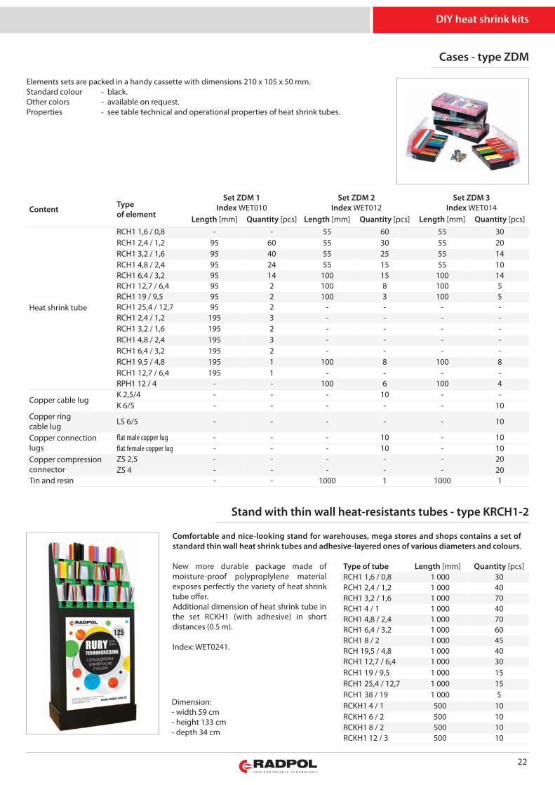
Elements sets are packed in a handy cassette with dimensions 210 x 105 x 50 mm.Standard colour - black.Other colors - available on request.Properties - see table technical and operational properties of heat shrink tubes.
DIY heat shrink kits
Cases - type ZDM
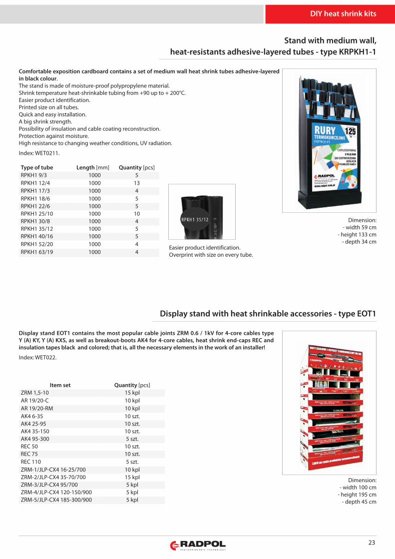
Comfortable and nice-looking stand for warehouses, mega stores and shops contains a set ofstandard thin wall heat shrink tubes and adhesive-layered ones of various diameters and colours.
New more durable package made ofmoisture-proof polyproplylene materialexposes perfectly the variety of heat shrinktube offer. Additional dimension of heat shrink tube inthe set RCKH1 (with adhesive) in shortdistances (0.5 m).
Index: WET0241.
Stand with thin wall heat-resistants tubes - type KRCH1-2
Dimension:- width 59 cm- height 133 cm- depth 34 cm
Type of tube Length [mm] Quantity [pcs]RCH1 1,6 / 0,8 1 000 30RCH1 2,4 / 1,2 1 000 40RCH1 3,2 / 1,6 1 000 70RCH1 4 / 1 1 000 40RCH1 4,8 / 2,4 1 000 70RCH1 6,4 / 3,2 1 000 60RCH1 8 / 2 1 000 45RCH 19,5 / 4,8 1 000 40RCH1 12,7 / 6,4 1 000 30RCH1 19 / 9,5 1 000 15RCH1 25,4 / 12,7 1 000 15RCH1 38 / 19 1 000 5RCKH1 4 / 1 500 10RCKH1 6 / 2 500 10RCKH1 8 / 2 500 10RCKH1 12 / 3 500 10
23
Stand with medium wall,heat-resistants adhesive-layered tubes - type KRPKH1-1
Type of tube Length [mm] Quantity [pcs]RPKH1 9/3 1000 5RPKH1 12/4 1000 13RPKH1 17/3 1000 4RPKH1 18/6 1000 5RPKH1 22/6 1000 5RPKH1 25/10 1000 10RPKH1 30/8 1000 4RPKH1 35/12 1000 5RPKH1 40/16 1000 5RPKH1 52/20 1000 4RPKH1 63/19 1000 4
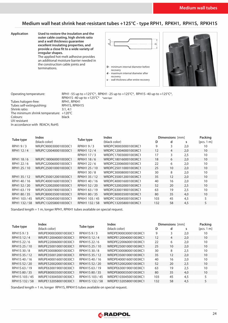
Comfortable exposition cardboard contains a set of medium wall heat shrink tubes adhesive-layeredin black colour.The stand is made of moisture-proof polypropylene material.Shrink temperature heat-shrinkable tubing from +90 up to + 200°C.Easier product identification.Printed size on all tubes.Quick and easy installation.A big shrink strength.Possibility of insulation and cable coating reconstruction.Protection against moisture.High resistance to changing weather conditions, UV radiation.
Index: WET0211.
Easier product identification.Overprint with size on every tube.
DIY heat shrink kits
Dimension:- width 59 cm
- height 133 cm- depth 34 cm
Display stand with heat shrinkable accessories - type EOT1
Item set Quantity [pcs]ZRM 1,5-10 15 kplAR 19/20-C 10 kplAR 19/20-RM 10 kplAK4 6-35 10 szt.AK4 25-95 10 szt.AK4 35-150 10 szt.AK4 95-300 5 szt.REC 50 10 szt.REC 75 10 szt.REC 110 5 szt.ZRM-1/JLP-CX4 16-25/700 10 kplZRM-2/JLP-CX4 35-70/700 15 kplZRM-3/JLP-CX4 95/700 5 kplZRM-4/JLP-CX4 120-150/900 5 kplZRM-5/JLP-CX4 185-300/900 5 kpl
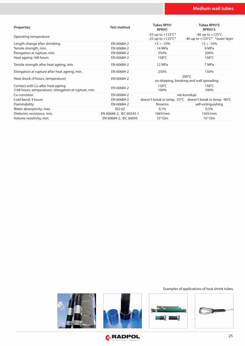
Display stand EOT1 contains the most popular cable joints ZRM 0.6 / 1kV for 4-core cables typeY (A) KY, Y (A) KXS, as well as breakout-boots AK4 for 4-core cables, heat shrink end-caps REC andinsulation tapes black and colored; that is, all the necessary elements in the work of an installer!
Index: WET022.
Dimension:- width 100 cm
- height 195 cm- depth 45 cm
24
Medium wall heat shrink heat-resistant tubes +125°C - type RPH1, RPKH1, RPH1S, RPKH1S
Tube typeIndex
Tube typeIndex Dimensions [mm] Packing
(black color) (black color) D d s [pcs. 1 m]RPH1 9 / 3 WRJPC9000300010030C1 RPKH1 9 / 3 WRDPC900030001003KC1 9 3 2,0 10RPH1 12 / 4 WRJPC1200400010030C1 RPKH1 12 / 4 WRDPC120040001003KC1 12 4 2,0 10
RPKH1 17 / 3 WRDPC170030001003KC1 17 3 2,5 10RPH1 18 / 6 WRJPC1800600010030C1 RPKH1 18 / 6 WRDPC180160001003KC1 18 6 2,0 10RPH1 22 / 6 WRJPC2200600010030C1 RPKH1 22 / 6 WRDPC220060001003KC1 22 6 2,0 10RPH1 25 / 10 WRJPC2500100010030C1 RPKH1 25 / 10 WRDPC250110001003KC1 25 10 2,0 10
RPKH1 30 / 8 WRDPC300080001003KC1 30 8 2,0 10RPH1 35 / 12 WRJPC3500120010030C1 RPKH1 35 / 12 WRDPC350012001003KC1 35 12 2,0 10RPH1 40 / 16 WRJPC4000160010030C1 RPKH1 40 / 16 WRDPC400016001003KC1 40 16 2,0 10RPH1 52 / 20 WRJPC5200200010030C1 RPKH1 52 / 20 WRDPC520020001003KC1 52 20 2,5 10RPH1 63 / 19 WRJPC6300190010030C1 RPKH1 63 / 19 WRDPC630019001003KC1 63 19 2,5 10RPH1 80 / 35 WRJPC8000350010030C1 RPKH1 80 / 35 WRDPC800035001003KC1 80 35 4,0 10RPH1 103 / 45 WRJPC1030450010030C1 RPKH1 103 / 45 WRDPC103045001003KC1 103 45 4,5 5RPH1 132 / 58 WRJPC1320580010030C1 RPKH1 132 / 58 WRDPC132058001003KC1 132 58 4,5 5
Used to restore the insulation and theouter cable coating, high shrink ratioand a wall thickness guaranteeexcellent insulating properties, andprovide a close fit to a wide variety ofirregular shapes.The applied hot-melt adhesive providesan additional moisture barrier needed inthe construction cable joints andterminations.
Standard length = 1 m, longer RPH1, RPKH1 tubes available on special request.
Tube typeIndex
Tube typeIndex Dimensions [mm] Packing
(black color) (black color) D d s [pcs. 1 m]RPH1S 9 / 3 WRJPE9000300010030C1 RPKH1S 9 / 3 WRDPE900030001003KC1 9 3 2,0 10RPH1S 12 / 4 WRJPE1200400010030C1 RPKH1S 12 / 4 WRDPE120040001003KC1 12 4 2,0 10RPH1S 22 / 6 WRJPE2200600010030C1 RPKH1S 22 / 6 WRDPE220060001003KC1 22 6 2,0 10RPH1S 25 / 10 WRJPE2500100010030C1 RPKH1S 25 / 10 WRDPE250010001003KC1 25 10 2,0 10RPH1S 30 / 8 WRJPE3000800010030C1 RPKH1S 30 / 8 WRDPE300080001003KC1 30 8 2,5 10RPH1S 35 / 12 WRJPE3500120010030C1 RPKH1S 35 / 12 WRDPE350010001003KC1 35 12 2,0 10RPH1S 40 / 16 WRJPE4000160010030C1 RPKH1S 40 / 16 WRDPE400016001003KC1 40 16 2,0 10RPH1S 52 / 20 WRJPE5200200010030C1 RPKH1S 52 / 20 WRDPE520020001003KC1 52 20 2,5 10RPH1S 63 / 19 WRJPE6300190010030C1 RPKH1S 63 / 19 WRDPE630019001003KC1 63 19 2,5 10RPH1S 80 / 35 WRJPE8000350010030C1 RPKH1S 80 / 35 WRDPE800035001003KC1 80 35 4,0 10RPH1S 103 / 45 WRJPE1030450010030C1 RPKH1S 103 / 45 WRDPE103045001003KC1 103 45 4,5 5RPH1S 132 / 58 WRJPE1320580010030C1 RPKH1S 132 / 58 WRDPE132058001003KC1 132 58 4,5 5
Standard length = 1 m, longer RPH1S, RPKH1S tubes available on special request.
Medium wall tubes
Operating temperature: RPH1 -55 up to +125°C*, RPKH1 -25 up to +125°C*, RPH1S -40 up to +125°C*, RPKH1S -40 up to +125°C* *outer layer
Tubes halogen-free: RPH1, RPKH1Tubes self-extinguishing: RPH1S, RPKH1SShrink ratio: 3:1, 4:1The minimum shrink temperature: +120°CColours: blackUV resistantIn accordance with REACH, RoHS
Application
s
Dd
D - minimum internal diameter before recoveryd - maximum internal diameter after recoverys - wall thickness after entire recovery
25
Medium wall tubes
Properties Test method Tubes RPH1RPKH1
Tubes RPH1SRPKH1S
Operating temperature -55 up to +125°C*-25 up to +125°C*
-40 up to +125°C-40 up to +125°C* *outer layer
Length change after shrinking EN 60684-2 +5 ÷ -10% +5 ÷ -10%Tensile strength, min. EN 60684-2 14 MPa 9 MPaElongation at rupture, min. EN 60684-2 350% 200%Heat ageing 168 hours EN 60684-2 158°C 158°C
Tensile strength after heat ageing, min. EN 60684-2 12 MPa 7 MPa
Elongation at rupture after heat ageing, min. EN 60684-2 250% 150%
Heat shock (4 hours, temperature) EN 60684-2 200°Cno dripping, breaking and wall spreading
Contact with Cu after heat ageing(168 hours, temperature): elongation at rupture, min. EN 60684-2 158°C
100%158°C100%
Cu corrosion EN 60684-2 nie korodujeCold bend; 4 hours EN 60684-2 doesn't break in temp. -55°C doesn't break in temp. -40°CFlammability EN 60684-2 firearms self-extinguishingWater absorptivity, max ISO 62 0,1% 0,5%Dielectric resistance, min. EN 60684-2; IEC 60243-1 16kV/mm 15kV/mmVolume resistivity, min. EN 60684-2; IEC 60093 1012Ωm 1011Ωm
Examples of applications of heat shrink tubes.
26
Medium wall heat shrink tubes with mastic - type RPM
Tube type IndekxDimensions [mm] Packing
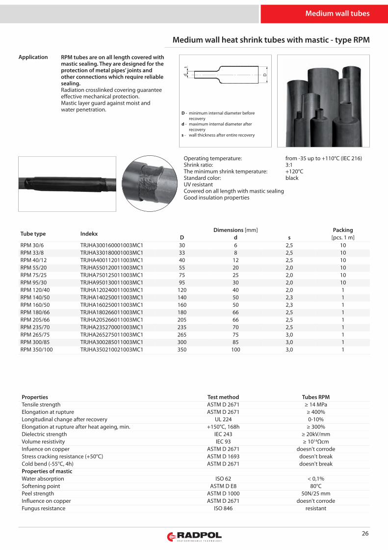
D d s [pcs. 1 m]RPM 30/6 TRJHA300160001003MC1 30 6 2,5 10RPM 33/8 TRJHA330180001003MC1 33 8 2,5 10RPM 40/12 TRJHA400112011003MC1 40 12 2,5 10RPM 55/20 TRJHA550120011003MC1 55 20 2,0 10RPM 75/25 TRJHA750125011003MC1 75 25 2,0 10RPM 95/30 TRJHA950130011003MC1 95 30 2,0 10RPM 120/40 TRJHA120240011003MC1 120 40 2,0 1RPM 140/50 TRJHA140250011003MC1 140 50 2,3 1RPM 160/50 TRJHA160250011003MC1 160 50 2,3 1RPM 180/66 TRJHA180266011003MC1 180 66 2,5 1RPM 205/66 TRJHA205266011003MC1 205 66 2,5 1RPM 235/70 TRJHA235270001003MC1 235 70 2,5 1RPM 265/75 TRJHA265275011003MC1 265 75 3,0 1RPM 300/85 TRJHA300285011003MC1 300 85 3,0 1RPM 350/100 TRJHA350210021003MC1 350 100 3,0 1
RPM tubes are on all length covered withmastic sealing. They are designed for theprotection of metal pipes’ joints andother connections which require reliablesealing.Radiation crosslinked covering guaranteeeffective mechanical protection.Mastic layer guard against moist andwater penetration.
Properties Test method Tubes RPMTensile strength ASTM D 2671 ≥ 14 MPaElongation at rupture ASTM D 2671 ≥ 400%Longitudinal change after recovery UL 224 0-10%Elongation at rupture after heat ageing, min. +150°C, 168h ≥ 300%Dielectric strength IEC 243 ≥ 20kV/mmVolume resistivity IEC 93 ≥ 1014ΩcmInfuence on copper ASTM D 2671 doesn't corrodeStress cracking resistance (+50°C) ASTM D 1693 doesn't breakCold bend (-55°C, 4h) ASTM D 2671 doesn't breakProperties of masticWater absorption ISO 62 < 0,1%Softening point ASTM D E8 80°CPeel strength ASTM D 1000 50N/25 mmInfluence on copper ASTM D 2671 doesn't corrodeFungus resistance ISO 846 resistant
Medium wall tubes
Operating temperature: from -35 up to +110°C (IEC 216)Shrink ratio: 3:1The minimum shrink temperature: +120°CStandard color: blackUV resistantCovered on all length with mastic sealingGood insulation properties
Application
s
Dd
D - minimum internal diameter before recoveryd - maximum internal diameter after recoverys - wall thickness after entire recovery
27
Heat shrink tubes of large diameters - type RDK, RDM, RD
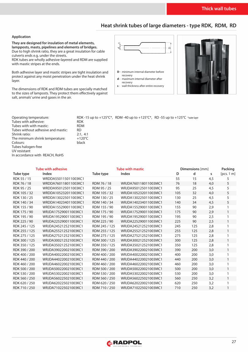
They are designed for insulation of metal elements,lampposts, masts, pipelines and elements of bridges.Due to high shrink ratio, they are a great insulation for cableculverts ends e.g. under the streets.RDK tubes are wholly adhesive-layered and RDM are suppliedwith mastic stripes at the ends.
Both adhesive layer and mastic stripes are tight insulation andprotect against any moist penetration under the heat shrinklayer.
The dimensions of RDK and RDM tubes are specially matchedto the sizes of lamposts. They protect them effectively againstsalt, animals’ urine and gases in the air.
Thick wall tubes
Operating temperature: RDK -15 up to +125°C*, RDM -40 up to +125°C*, RD -55 up to +125°C *outer layerTubes with adhesive: RDKTubes with with mastic: RDMTubes without adhesive and mastic: RDShrink ratio: 2:1, 4:1The minimum shrink temperature: +120°CColours: blackTubes halogen-freeUV resistantIn accordance with REACH, RoHS
s
Dd
D - minimum internal diameter before recoveryd - maximum internal diameter after recoverys - wall thickness after entire recovery
Tube with adhesive Tube with mastic Dimensions [mm] PackingTube type Index Tube type Index D d s [pcs. 1 m]RDK 55 / 15 WRDDA550115011003KC1 55 15 4,5 5RDK 76 / 18 WRDDA760118011003KC1 RDM 76 / 18 WRJDA760118011003MC1 76 18 4,0 5RDK 95 / 25 WRDDA950125011003KC1 RDM 95 / 25 WRJDA950125011003MC1 95 25 4,5 5RDK 105 / 32 WRDDA105232011003KC1 RDM 105 / 32 WRJDA105232011003MC1 105 32 4,0 5RDK 130 / 25 WRDDA130225011003KC1 RDM 130 / 25 WRJDA130225011003MC1 130 25 4,5 5RDK 140 / 34 WRDDA140234011003KC1 RDM 140 / 34 WRJDA140234011003MC1 140 34 4,5 5RDK 155 / 90 WRDDA155290011003KC1 RDM 155 / 90 WRJDA155290011003MC1 155 90 2,9 1RDK 175 / 90 WRJDA175290011003KC1 RDM 175 / 90 WRJDA175290011003MC1 175 90 2,9 1RDK 195 / 90 WRJDA195290011003KC1 RDM 195 / 90 WRJDA195290011003MC1 195 90 2,5 1RDK 225 / 90 WRJDA225290011003KC1 RDM 225 / 90 WRJDA225290011003MC1 225 90 2,5 1RDK 245 / 125 WRJDA245212521003KC1 RDM 245 / 125 WRJDA245212521003MC1 245 125 2,8 1RDK 255 / 125 WRJDA255212521003KC1 RDM 255 / 125 WRJDA255212521003MC1 255 125 2,8 1RDK 275 / 125 WRJDA275212521003KC1 RDM 275 / 125 WRJDA275212521003MC1 275 125 2,8 1RDK 300 / 125 WRJDA300212521003KC1 RDM 300 / 125 WRJDA300212521003MC1 300 125 2,8 1RDK 350 / 125 WRJDA350212521003KC1 RDM 350 / 125 WRJDA350212521003MC1 350 125 2,8 1RDK 390 / 200 WRJDA390220021003KC1 RDM 390 / 200 WRJDA390220021003MC1 390 200 3,0 1RDK 400 / 200 WRJDA400220021003KC1 RDM 400 / 200 WRJDA400220021003MC1 400 200 3,0 1RDK 440 / 200 WRJDA440220021003KC1 RDM 440 / 200 WRJDA440220021003MC1 440 200 3,0 1RDK 460 / 200 WRJDA460220021003KC1 RDM 460 / 200 WRJDA460220021003MC1 460 200 3,0 1RDK 500 / 200 WRJDA500220021003KC1 RDM 500 / 200 WRJDA500220021003MC1 500 200 3,0 1RDK 530 / 200 WRJDA530220021003KC1 RDM 530 / 200 WRJDA530220021003MC1 530 200 3,0 1RDK 560 / 250 WRJDA560225021003KC1 RDM 560 / 250 WRJDA560225021003MC1 560 250 3,2 1RDK 620 / 250 WRJDA620225021003KC1 RDM 620 / 250 WRJDA620220021003MC1 620 250 3,2 1RDK 710 / 250 WRJDA710225021003KC1 RDM 710 / 250 WRJDA710225021003MC1 710 250 3,2 1
Application
28
Properties Test method Tubes RDK / RDM / RDOperating temperature -15 up to +125°C / -40 up to +125°C / -55up to +125°C *outer layer
Length change after shrinking EN 60684-2 +5 ÷ -15%Tensile strength, min EN 60684-2 12 MPaElongation at rupture, min. EN 60684-2 300%Heat ageing (168 h, temperature) EN 60684-2 158°CTensile strength after heat ageing, min. EN 60684-2 10 MPaElongation at rupture after heat ageing, min. EN 60684-2 200%
Heat shock (4 hours, temperature) EN 60684-2 200°Cno dripping, breaking and wall spreadi
Contact with Cu after heat ageing(168 hours, temperature): elongation at rupture, min. EN 60684-2 158°C
100%Cu corrosion EN 60684-2 doesn't corrodeeCold bend; 4 hours EN 60684-2 doesn't break in temp. -55°CFlammability EN 60684-2 firearmsWater absorptivity, max ISO 62 0,1%Dielectric resistance, min. EN 60684-2; IEC 60243-1 16kV/mmVolume resistivity, min. EN 60684-2; IEC 60093 1012Ωm
Thick wall tubes
Standard length 1 m. Up to the dimension 140/34 lengths > 1 m are possible.On special demand we can produce tubes of non standard sizes.
Tube without adhesive and mastic Dimensions [mm] PackingTube type Index D d s [pcs. 1 m]RD 55 / 15 WRJDA5501150110030C1 55 15 4,5 5RD 76 / 18 WRJDA7601180110030C1 76 18 4,0 5RD 95 / 25 WRJDA9501250110030C1 95 25 4,5 5RD 105 / 32 WRJDA1052320110030C1 105 32 4,0 5RD 130 / 25 WRJDA1302250110030C1 130 25 4,5 5RD 140 / 34 WRJDA1402340110030C1 140 34 4,5 5RD 155 / 90 WRJDA1552900110030C1 155 90 2,9 1RD 175 / 90 WRJDA1750900010030C1 175 90 2,9 1RD 195 / 90 WRJDA1952900110030C1 195 90 2,5 1RD 225 / 90 WRJDA2252900110030C1 225 90 2,5 1RD 245 / 125 WRJDA2452125210030C1 245 125 2,8 1RD 255 / 125 WRJDA2552125210030C1 255 125 2,8 1RD 275 / 125 WRJDA2752125210030C1 275 125 2,8 1RD 300 / 125 WRJDA3002125210030C1 300 125 2,8 1RD 350 / 125 WRJDA3502125210030C1 350 125 2,8 1RD 390 / 200 WRJDA3902200210030C1 390 200 3,0 1RD 400 / 200 WRJDA4002200210030C1 400 200 3,0 1RD 440 / 200 WRJDA4402200210030C1 440 200 3,0 1RD 460 / 200 WRJDA4602200210030C1 460 200 3,0 1RD 500 / 200 WRJDA5002200210030C1 500 200 3,0 1RD 530 / 200 WRJDA5302200210030C1 530 200 3,0 1RD 560 / 250 WRJDA5602250210030C1 560 250 3,2 1RD 620 / 250 WRJDA6202250210030C1 620 250 3,2 1RD 710 / 250 WRJDA7102250210030C1 710 250 3,2 1
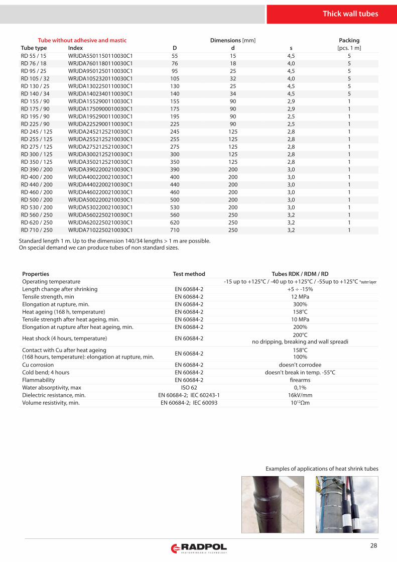
Examples of applications of heat shrink tubes
29
Thick wall heat shrink tubes, adhesive-layered, high shrink ratio 6:1 - type RBG
Tube type IndexDimensions [mm Packing Cut into
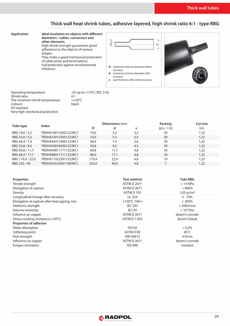
D d s [pcs. 1 m] [m]RBG 19,0 / 3,2 TRDHA190132001223KC1 19,0 3,2 3,2 20 1,22RBG 33,0 / 5,5 TRDHA330155001223KC1 33,0 5,5 3,4 20 1,22RBG 44,4 / 7,4 TRDHA444174001223KC1 44,4 7,4 3,6 20 1,22RBG 50,8 / 8,3 TRDHA508183001223KC1 50,8 8,3 4,3 20 1,22RBG 69,8 / 11,7 TRDHA698111711223KC1 69,8 11,7 4,8 20 1,22RBG 88,9 / 17,1 TRDHA889117111223KC1 88,9 17,1 4,8 20 1,22RBG 119,4 / 22,9 TRDHA119222911223KC1 119,4 22,9 4,8 10 1,22RBG 235 / 40 TRDHA235240011003KC1 235,0 40,0 4,8 1 1,22
Ideal insulation on objects with differentdiameters - cables, connectors andother elements.High shrink strength guarantees goodadherence to the objects of variousshapes. They make a good mechanical protectionof cable joints and terminations.Full protection against environmentalinfluence.
Properties Test method Tubs RBGTensile strength ASTM D 2671 > 14 MPaElongation at rupture ASTM D 2671 > 400%Density ASTM D 792 1,05 g/cm3
Longitudinal change after recovery UL 224 0 - 10%Elongation at rupture after heat ageing, min. +150°C, 168 ч > 300%Dielectric strength IEC 243 > 20kV/mmVolume resistivity IEC 93 > 1014ΩmInfuence on copper ASTM D 2671 doesn't corrodeStress cracking resistance (+50°C) ASTM D 1 693 doesn't breakProperties of adhesiveWater absorption ISO 62 < 0,2%Softening point ASTM D E8 85°CPeel strength DIN 30672 4 N/cmInfluence on copper ASTM D 2671 doesn't corrodeFungus resistance ISO 846 resistant
Thick wall tubes
Operating temperature: -55 up to +110°C (IEC 216)Shrink ratio: 6:1The minimum shrink temperature: +120°CColours: blackUV resistantVery high mechanical protection
Application
s
Dd
D - minimum internal diameter before recoveryd - maximum internal diameter after recoverys - wall thickness after entire recovery
30
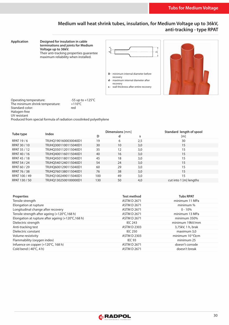
Medium wall heat shrink tubes, insulation, for Medium Voltage up to 36kV,anti-tracking - type RPAT
Tube type IndexDimensions [mm] Standard length of spool
D d s [m]RPAT 19 / 6 TRJHQ1901600030040D1 19 6 2,5 30RPAT 30 / 10 TRJHQ3001100115040D1 30 10 3,0 15RPAT 35 / 12 TRJHQ3501120115040D1 35 12 3,0 15RPAT 40 / 16 TRJHQ4001160115040D1 40 16 3,0 15RPAT 45 / 18 TRJHQ4501180115040D1 45 18 3,0 15RPAT 54 / 24 TRJHQ5401240115040D1 54 24 3,0 15RPAT 60 / 29 TRJHQ6001290115040D1 60 29 3,0 15RPAT 76 / 38 TRJHQ7601380115040D1 76 38 3,0 15RPAT 100 / 49 TRJHQ1002490115040D1 100 49 3,0 15RPAT 130 / 50 TRJHQ1302500100000D1 130 50 4,0 cut into 1 [m] lengths
Designed for insulation in cableterminations and joints for MediumVoltage up to 36kV.Their anti-tracking properties guaranteemaximum reliability when installed.
Properties Test method Tubs RPATTensile strength ASTM D 2671 minimum 11 MPaElongation at rupture ASTM D 2671 minimum %Longitudinal change after recovery ASTM D 2671 0 - 10%Tensile strength after ageing (+120°C,168 h) ASTM D 2671 minimum 13 MPaElongation at rupture after ageing (+120°C,168 h) ASTM D 2671 minimum 350%Dielectric strength IEC 243 minimum 19kV/mmAnti-tracking test ASTM D 2303 3,75kV, 1 h, brakDielectric constant IEC 250 maximum 3,0Volume resistivity ASTM D 2303 minimum 1013ΩcmFlammability (oxygen index) IEC 93 minimum 25Infuence on copper (+120°C, 168 h) ASTM D 2671 doesn't corrodeCold bend (-40°C, 4 h) ASTM D 2671 doesn't break
Tubs for Medium Voltage
Operating temperature: -55 up to +125°CThe minimum shrink temperature: +110°CStandard color: redHalogen-freeUV resistantProduced from special formula of radiation crosslinked polyethylene
Application
s
Dd
D - minimum internal diameter before recoveryd - maximum internal diameter after recoverys - wall thickness after entire recovery
31
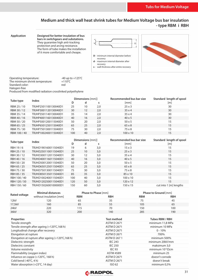
Medium and thick wall heat shrink tubes for Medium Voltage bus bar insulation- type RBM i RBH
Tube type IndexDimensions [mm]] Recommended bus bar size Standard length of spool
D d s [mm] [m]RBM 25 / 10 TRJHP2501100130040D1 25 10 2,0 25 x 3 30RBM 30 / 12 TRJHP3001120130040D1 30 12 2,0 35 x 4 30RBM 35 / 14 TRJHP3501140130040D1 35 14 2,0 35 x 4 30RBM 40 / 16 TRJHP4001160130040D1 40 16 2,0 40 x 5 30RBM 50 / 20 TRJHP5001200115040D1 50 20 2,0 50 x 5 15RBM 65 / 25 TRJHP6501250115040D1 65 25 2,0 65 x 8 15RBM 75 / 30 TRJHP7501300115040D1 75 30 2,0 75 x 8 15RBM 100 / 40 TRJHP1002400115040D1 100 40 2,0 100 x 10 15
Designed for better insulation of busbars in switchgears and substations.They guarantee high anti-trackingprotection and arcing resistance. The form of tube makes the installationof it more comfortable and cheape.
Properties Test method Tubes RBM / RBHTensile strength ASTM D 2671 minimum 11,8 MPaTensile strength after ageing (+120°C,168 h) ASTM D 2671 minimum 10 MPaLongitudinal change after recovery ASTM D 2671 0 - 10%Elongation at rupture ASTM D 2671 700%Elongation at rupture after ageing (+120°C,168 h) ASTM D 267 1 minimum 500%Dielectric strength IEC 243 minimum 20kV/mmDielectric constant IEC 250 maksimum 3,0Volume resistivity IEC 93 minimum 1013ΩcmFlammability (oxygen index) ASTM 4589 minimum 25Infuence on coppe (+120°C, 168 h) ASTM D 2671 doesn't corrodeCold bend (-40°C, 4 h) ASTM D 2671 doesn't breakWater absorption (+23°C, 14 day) ISO 62 minimum 0,5%
Tube type IndexDimensions [mm]] Recommended bus bar size Standard length of spool
D d s [mm] [m]RBH 19 / 6 TRJHO1901600115040D1 19 6 3,0 15 x 3 15RBH 25 / 10 TRJHO2501100115040D1 25 10 3,0 25 x 3 15RBH 30 / 12 TRJHO3001120115040D1 30 12 3,0 35 x 4 15RBH 40 / 16 TRJHO4001160115040D1 40 16 3,0 40 x 5 15RBH 50 / 20 TRJHO5001200115040D1 50 20 3,0 50 x 5 15RBH 65 / 25 TRJHO6501250115040D1 65 25 3,0 65 x 8 15RBH 75 / 30 TRJHO7501300115040D1 75 30 3,0 75 x 8 15RBH 85 / 35 TRJHO8501350115040D1 85 35 3,0 85 x 10 15RBH 100 / 40 TRJHO1002400115040D1 100 40 3,0 100 x 10 15RBH 120 / 50 TRJHO1202500115040D1 120 50 3,0 120 x 12 15RBH 150 / 60 TRJHO1502600100000D1 150 60 3,0 150 x 15 cut into 1 [m] lengths
Rated voltageMinimal distances Phase to Phase [mm] Phase to Ground [mm]
without insulation [mm] RBM RBH RBM RBH12kV 120 65 35 75 4517,5kV 160 85 55 105 6524kV 220 115 70 150 10036kV 320 200 140 285 190
Tubs for Medium Voltage
Operating temperature: -40 up to +125°CThe minimum shrink temperature: +110°CStandard color: redHalogen-freeProduced from modified radiation crosslinked polyethylene
Application
s
Dd
D - minimum internal diameter before recoveryd - maximum internal diameter after recoverys - wall thickness after entire recovery

32
Insulating tapes for bus bars - typu RTBB
Tube type IndexWymiary [mm] Packing Standard lengt
Width Thickness after recovery [pcs] [m]RTBB-1 TTHS0025051 25 1,00 + 0,10 1 5RTBB-2 TTHS0050051 50 1,00 + 0,15 1 5
They are very flexible and easy to install. They are designed for bus barinsulation in all the places the tube could not be installed.Guarantee a good electrical and percussive insulation of bus bars up to 24kV. Easy to remove for review or maintenance.
Properties Test method Tubs RTBBTensile strength ASTM D 638 minimum 13 MPaTensile strength after ageing (+120°C,168 h) ASTM D 2671 minimum 10 MPaLongitudinal change after recovery ASTM D 638 550%Elongation at rupture after ageing (+120°C,168 h) ASTM D 2671 minimum 450%Dielectric strength IEC 243 minimum 20kV/mmDielectric constant IEC 250 maximum 3,0Volume resistivity IEC 93 minimum 1013ΩcmFlammability ASTM D 2671 self-extinguishing after 60 sInfuence on copper (+120°C, 168 h) ASTM D 2671 doesn't corrodWater absorption (+23°C, 14 dni) ISO 62 minimum 0,5%Shrink ratio 30%
Insulating tapes
Operating temperature: -55 up to +105°CThe minimum shrink temperature: +110°CStandard color: redUV resistantProduced from radiation crosslinked polyethylene
Application
33
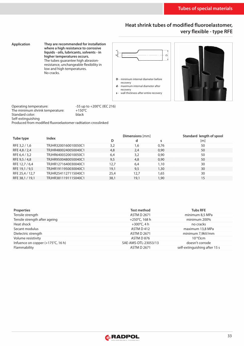
Heat shrink tubes of modified fluoroelastomer,very flexible - type RFE
Tube type IndexDimensions [mm] Standard length of spool
D d s [m]RFE 3,2 / 1,6 TRJHR3200160010050C1 3,2 1,6 0,76 50RFE 4,8 / 2,4 TRJHR4800240050040C1 4,8 2,4 0,90 50RFE 6,4 / 3,2 TRJHR6400320010050C1 6,4 3,2 0,90 50RFE 9,5 / 4,8 TRJHR9500480050040C1 9,5 4,8 0,90 50RFE 12,7 / 6,4 TRJHR1271640030040C1 12,7 6,4 1,10 30RFE 19,1 / 9,5 TRJHR1911950030040C1 19,1 9,5 1,30 30RFE 25,4 / 12,7 TRJHR2541127115040C1 25,4 12,7 1,65 30RFE 38,1 / 19,1 TRJHR3811191115040C1 38,1 19,1 1,90 15
They are recommended for installationwhere a high resistance to corrosiveliquids - oils, lubricants, solvents - inhigher temperatures occurs.The tubes guarantee high abrasion-resistance, unchangeable flexibility inlow and high temperatures.No cracks.
Properties Test method Tubs RFETensile strength ASTM D 2671 minimum 8,5 MPaTensile strength after ageing +250°C, 168 h minimum 200%Heat shock +300°C, 4 h no cracksSecant modulus ASTM D 412 maximum 13,8 MPaDielectric strength ASTM D 2671 minimum 7,9kV/mmVolume resistivity ASTM D 876 1014ΩcmInfuence on copper (+175°C, 16 h) SAE-AMS-DTL-23053/13 doesn't corrodeFlammability ASTM D 2671 self-extinguishing after 15 s
Tubes of special materials
Operating temperature: -55 up to +200°C (IEC 216)The minimum shrink temperature: +150°CStandard color: blackSelf-extinguishingProduced from modified fluoroelastomer radtiation crosslinked
Application
s
Dd
D - minimum internal diameter before recoveryd - maximum internal diameter after recoverys - wall thickness after entire recovery
34
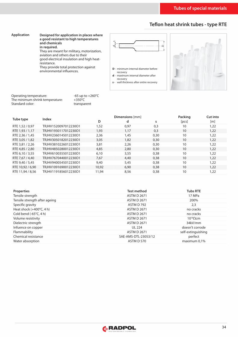
Teflon heat shrink tubes - type RTE
Tube type IndexDimensions [mm] Packing Cut into
D d s [pcs] [m]RTE 1,52 / 0,97 TRJHV1520097012230O1 1,52 0,97 0,3 10 1,22RTE 1,93 / 1,17 TRJHV1930117012230O1 1,93 1,17 0,3 10 1,22RTE 2,36 / 1,45 TRJHV2360145012230O1 2,36 1,45 0,30 10 1,22RTE 3,05 / 1,82 TRJHV3050182012230O1 3,05 1,82 0,30 10 1,22RTE 3,81 / 2,26 TRJHV3810226012230O1 3,81 2,26 0,30 10 1,22RTE 4,85 / 2,80 TRJHV4850280012230O1 4,85 2,80 0,30 10 1,22RTE 6,10 / 3,55 TRJHV6100355012230O1 6,10 3,55 0,38 10 1,22RTE 7,67 / 4,40 TRJHV7670440012230O1 7,67 4,40 0,38 10 1,22RTE 9,40 / 5,45 TRJHV9400545012230O1 9,40 5,45 0,38 10 1,22RTE 10,92 / 6,90 TRJHV1091690012230O1 10,92 6,90 0,38 10 1,22RTE 11,94 / 8,56 TRJHV1191856012230O1 11,94 8,56 0,38 10 1,22
Designed for application in places wherea good resistant to high temperaturesand chemicalsin required.They are meant for military, motorization,aviation and others due to theirgood electrical insulation and high heat-resistance.They provide total protection againstenvironmental influences.
Properties Test method Tubs RTETensile strength ASTM D 2671 17 MPaTensile strength after ageing ASTM D 2671 200%Specific gravity ASTM D 792 2,3Heat shock (+400°C, 4 h) ASTM D 2671 no cracksCold bend (-65°C, 4 h) ASTM D 2671 no cracksVolume resistivity ASTM D 2671 1018ΩcmDielectric strength ASTM D 2671 34kV/mmInfuence on copper UL 224 doesn't corrodeFlammability ASTM D 2671 self-extinguishingChemical resistance SAE-AMS-DTL-23053/12 perfectWater absorption ASTM D 570 maximum 0,1%
Tubes of special materials
Operating temperature: -65 up to +260°CThe minimum shrink temperature: +350°CStandard color: transparent
Application
s
Dd
D - minimum internal diameter before recoveryd - maximum internal diameter after recoverys - wall thickness after entire recovery
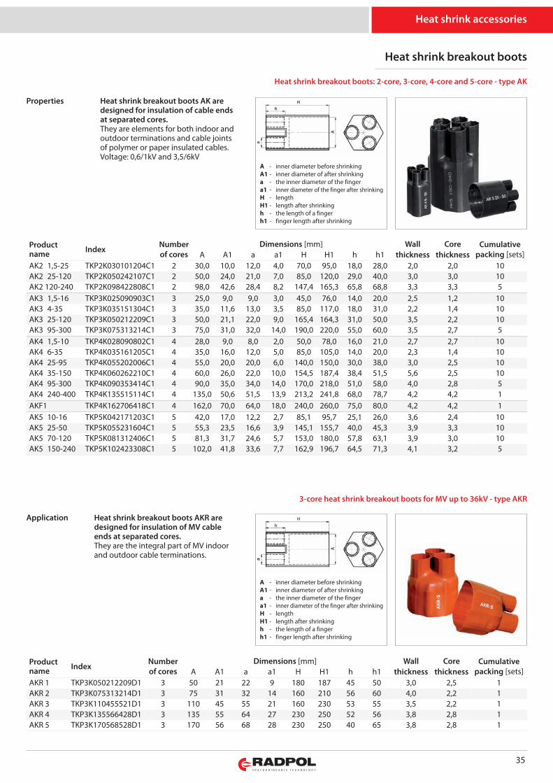
35
Heat shrink accessories
Heat shrink breakout boots
A - inner diameter before shrinkingA1 - inner diameter of after shrinkinga - the inner diameter of the fingera1 - inner diameter of the finger after shrinkingH - lengthH1 - length after shrinkingh - the length of a fingerh1 - finger length after shrinking
A - inner diameter before shrinkingA1 - inner diameter of after shrinkinga - the inner diameter of the fingera1 - inner diameter of the finger after shrinkingH - lengthH1 - length after shrinkingh - the length of a fingerh1 - finger length after shrinking
Productname Index Number
of coresDimensions [mm] Wall Core Cumulative
packing [sets]A A1 a a1 H H1 h h1 thickness thicknessAK2 1,5-25 TKP2K030101204C1 2 30,0 10,0 12,0 4,0 70,0 95,0 18,0 28,0 2,0 2,0 10AK2 25-120 TKP2K050242107C1 2 50,0 24,0 21,0 7,0 85,0 120,0 29,0 40,0 3,0 3,0 10AK2 120-240 TKP2K098422808C1 2 98,0 42,6 28,4 8,2 147,4 165,3 65,8 68,8 3,3 3,3 5AK3 1,5-16 TKP3K025090903C1 3 25,0 9,0 9,0 3,0 45,0 76,0 14,0 20,0 2,5 1,2 10AK3 4-35 TKP3K035151304C1 3 35,0 11,6 13,0 3,5 85,0 117,0 18,0 31,0 2,2 1,4 10AK3 25-120 TKP3K050212209C1 3 50,0 21,1 22,0 9,0 165,4 164,3 31,0 50,0 3,5 2,2 10AK3 95-300 TKP3K075313214C1 3 75,0 31,0 32,0 14,0 190,0 220,0 55,0 60,0 3,5 2,7 5AK4 1,5-10 TKP4K028090802C1 4 28,0 9,0 8,0 2,0 50,0 78,0 16,0 21,0 2,7 2,7 10AK4 6-35 TKP4K035161205C1 4 35,0 16,0 12,0 5,0 85,0 105,0 14,0 20,0 2,3 1,4 10AK4 25-95 TKP4K055202006C1 4 55,0 20,0 20,0 6,0 140,0 150,0 30,0 38,0 3,0 2,5 10AK4 35-150 TKP4K060262210C1 4 60,0 26,0 22,0 10,0 154,5 187,4 38,4 51,5 5,6 2,5 10AK4 95-300 TKP4K090353414C1 4 90,0 35,0 34,0 14,0 170,0 218,0 51,0 58,0 4,0 2,8 5AK4 240-400 TKP4K135515114C1 4 135,0 50,6 51,5 13,9 213,2 241,8 68,0 78,7 4,2 4,2 1AKF1 TKP4K162706418C1 4 162,0 70,0 64,0 18,0 240,0 260,0 75,0 80,0 4,2 4,2 1AK5 10-16 TKP5K042171203C1 5 42,0 17,0 12,2 2,7 85,1 95,7 25,1 26,0 3,6 2,4 10AK5 25-50 TKP5K055231604C1 5 55,3 23,5 16,6 3,9 145,1 155,7 40,0 45,3 3,9 3,3 10AK5 70-120 TKP5K081312406C1 5 81,3 31,7 24,6 5,7 153,0 180,0 57,8 63,1 3,9 3,0 10AK5 150-240 TKP5K102423308C1 5 102,0 41,8 33,6 7,7 162,9 196,7 64,5 71,3 4,1 3,2 5
Heat shrink breakout boots AK aredesigned for insulation of cable endsat separated cores. They are elements for both indoor andoutdoor terminations and cable jointsof polymer or paper insulated cables.Voltage: 0,6/1kV and 3,5/6kV
Heat shrink breakout boots: 2-core, 3-core, 4-core and 5-core - type AK
3-core heat shrink breakout boots for MV up to 36kV - type AKR
Heat shrink breakout boots AKR aredesigned for insulation of MV cableends at separated cores.They are the integral part of MV indoorand outdoor cable terminations.
Properties
Application
Productname Index Number
of coresDimensions [mm] Wall Core Cumulative
packing [sets]A A1 a a1 H H1 h h1 thickness thicknessAKR 1 TKP3K050212209D1 3 50 21 22 9 180 187 45 50 3,0 2,5 1AKR 2 TKP3K075313214D1 3 75 31 32 14 160 210 56 60 4,0 2,2 1AKR 3 TKP3K110455521D1 3 110 45 55 21 160 230 53 55 3,5 2,2 1AKR 4 TKP3K135566428D1 3 135 55 64 27 230 250 52 56 3,8 2,8 1AKR 5 TKP3K170568528D1 3 170 56 68 28 230 250 40 65 3,8 2,8 1
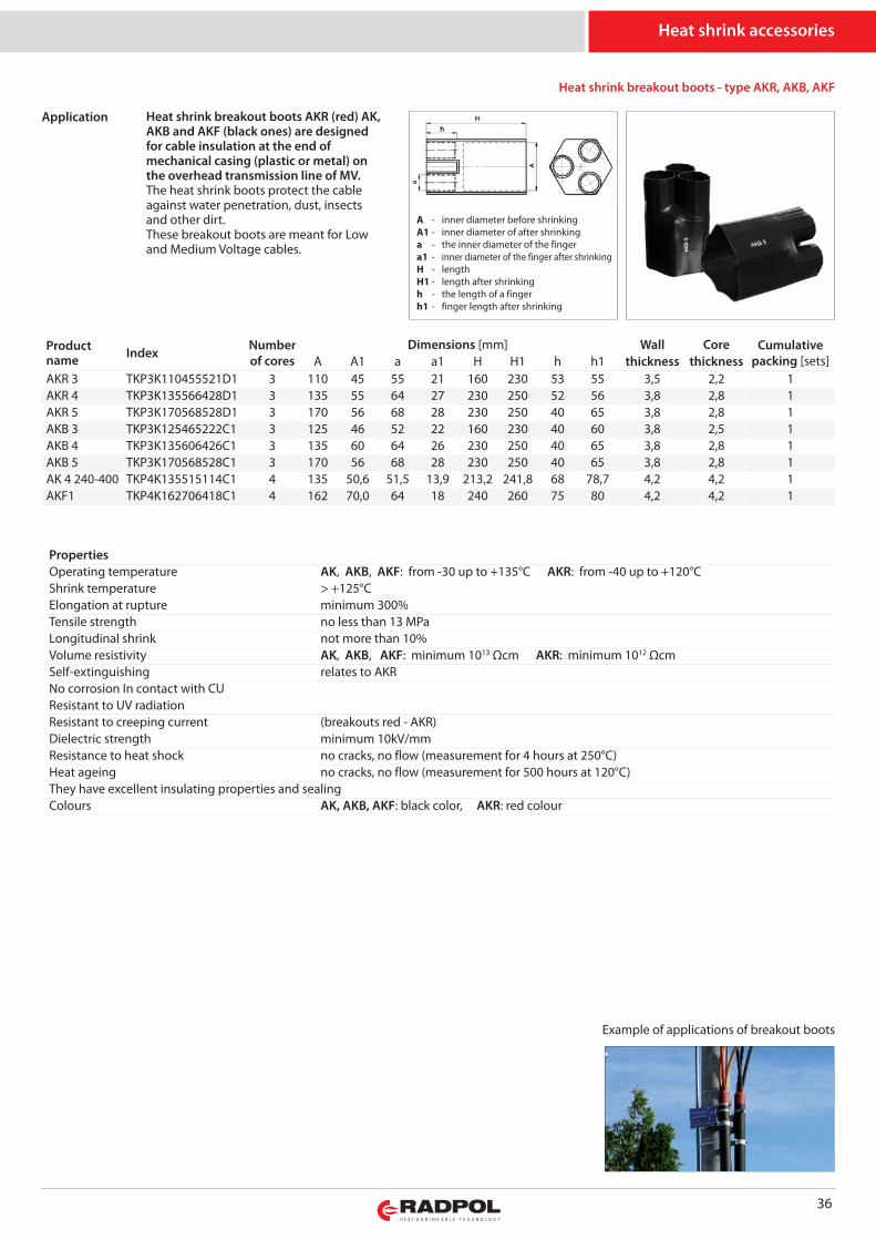
36
Heat shrink breakout boots - type AKR, AKB, AKF
Heat shrink breakout boots AKR (red) AK,AKB and AKF (black ones) are designedfor cable insulation at the end ofmechanical casing (plastic or metal) onthe overhead transmission line of MV.The heat shrink boots protect the cableagainst water penetration, dust, insectsand other dirt.These breakout boots are meant for Lowand Medium Voltage cables.
Heat shrink accessories
PropertiesOperating temperature AK, AKB, AKF: from -30 up to +135°C AKR: from -40 up to +120°CShrink temperature > +125°CElongation at rupture minimum 300%Tensile strength no less than 13 MPaLongitudinal shrink not more than 10%Volume resistivity AK, AKB, AKF: minimum 1013 Ωcm AKR: minimum 1012 ΩcmSelf-extinguishing relates to AKRNo corrosion In contact with CUResistant to UV radiationResistant to creeping current (breakouts red - AKR)Dielectric strength minimum 10kV/mmResistance to heat shock no cracks, no flow (measurement for 4 hours at 250°C)Heat ageing no cracks, no flow (measurement for 500 hours at 120°C)They have excellent insulating properties and sealingColours AK, AKB, AKF: black color, AKR: red colour
A - inner diameter before shrinkingA1 - inner diameter of after shrinkinga - the inner diameter of the fingera1 - inner diameter of the finger after shrinkingH - lengthH1 - length after shrinkingh - the length of a fingerh1 - finger length after shrinking
Application
Productname Index Number
of coresDimensions [mm] Wall Core Cumulative
packing [sets]A A1 a a1 H H1 h h1 thickness thicknessAKR 3 TKP3K110455521D1 3 110 45 55 21 160 230 53 55 3,5 2,2 1AKR 4 TKP3K135566428D1 3 135 55 64 27 230 250 52 56 3,8 2,8 1AKR 5 TKP3K170568528D1 3 170 56 68 28 230 250 40 65 3,8 2,8 1AKB 3 TKP3K125465222C1 3 125 46 52 22 160 230 40 60 3,8 2,5 1AKB 4 TKP3K135606426C1 3 135 60 64 26 230 250 40 65 3,8 2,8 1AKB 5 TKP3K170568528C1 3 170 56 68 28 230 250 40 65 3,8 2,8 1AK 4 240-400 TKP4K135515114C1 4 135 50,6 51,5 13,9 213,2 241,8 68 78,7 4,2 4,2 1AKF1 TKP4K162706418C1 4 162 70,0 64 18 240 260 75 80 4,2 4,2 1
Example of applications of breakout boots
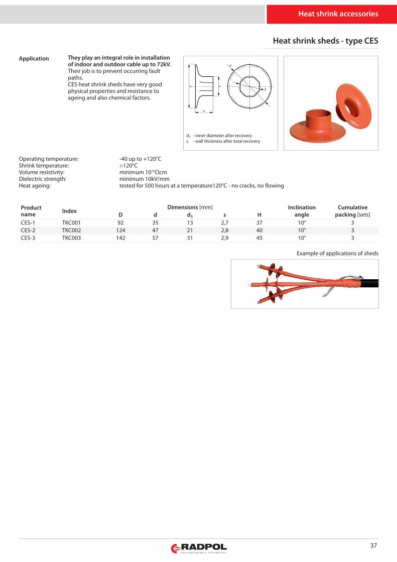
37
Heat shrink sheds - type CES
Heat shrink accessories
Productname Index
Dimensions [mm] Inclinationangle
Cumulativepacking [sets]D d d1 s H
CES-1 TKC001 92 35 13 2,7 37 10° 3CES-2 TKC002 124 47 21 2,8 40 10° 3CES-3 TKC003 142 57 31 2,9 45 10° 3
They play an integral role in installationof indoor and outdoor cable up to 72kV. Their job is to prevent occurring faultpaths.CES heat shrink sheds have very goodphysical properties and resistance toageing and also chemical factors.
Operating temperature: -40 up to +120°CShrink temperature: >120°CVolume resistivity: mi ni mum 1012ΩcmDielectric strength: mi ni mum 10kV/mmHeat ageing: tested for 500 hours at a temperature120°C - no cracks, no flowing
Example of applications of sheds
d1 - inner diameter after recoverys - wall thickness after total recovery
Application
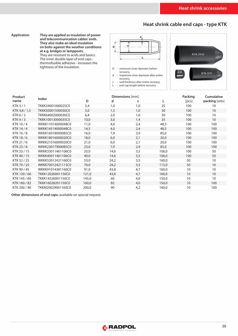
38
Heat shrink accessories
Heat shrink cable end caps - type KTK
They are applied as insulation of powerand telecommunication cables’ ends.They also make an ideal insulationon bolts against the weather conditionsat e.g. bridges or lampposts.They are resistant to acids and basics.The inner double layer of end caps -thermofusible adhesive - increases thetightness of the insulation. D - minimum inner diameter before
recovery,d - maximum inner diameter after entire
recovery,s - wall thickness after entire recovery,L - end cap length before recovery
Application
Productname Index
Dimensions [mm] Packing Cumulativepacking [sets]D d s L [pcs]
KTK 3 / 1 TKKK34001000025C0 3,4 1,0 1,0 25 100 10KTK 4,8 / 1,5 TKKK50001500030C0 5,0 1,5 1,0 30 100 10KTK 6 / 2 TKKK64002000030C0 6,4 2,0 1,0 30 100 10KTK 9 / 3 TKKK10013000035C0 10,0 3,0 1,4 35 100 10KTK 10 / 4 WKKK11014000048C0 11,0 4,0 2,4 48,5 100 100KTK 14 / 4 WKKK14514000048C0 14,5 4,0 2,4 48,5 100 100KTK 16 / 8 WKKK16018000085C0 16,0 7,9 2,9 85,0 100 100KTK 18 / 6 WKKK18016000020C0 18,0 6,0 2,1 20,0 100 100KTK 21 / 6 WKKK21016000020C0 21,0 6,0 2,1 20,0 100 100KTK 23 / 8 WKKK23017900085C0 23,0 7,9 2,9 85,0 100 100KTK 33 / 15 WKKK33011461106C0 33,0 14,6 3,5 106,0 100 50KTK 40 / 15 WKKK40011461106C0 40,0 14,6 3,5 106,0 100 50KTK 52 / 25 WKKK53012421160C0 53,0 24,2 3,5 160,0 50 10KTK 70 / 25 WKKK70012421115C0 70,0 24,2 3,5 115,0 50 10KTK 90 / 45 WKKK91014381160C0 91,0 43,8 4,7 160,0 10 10KTK 120 / 60 TKKK12026001150C0 121,0 43,8 4,7 160,0 10 10KTK 145 / 60 TKKK14526001150C0 145,0 60 4,0 150,0 10 10KTK 160 / 82 TKKK16028201150C0 160,0 82 4,0 150,0 10 100KTK 200 / 90 TKKM20029001160C0 200,0 90 4,2 160,0 10 100
Other dimensions of end caps: available on special request.
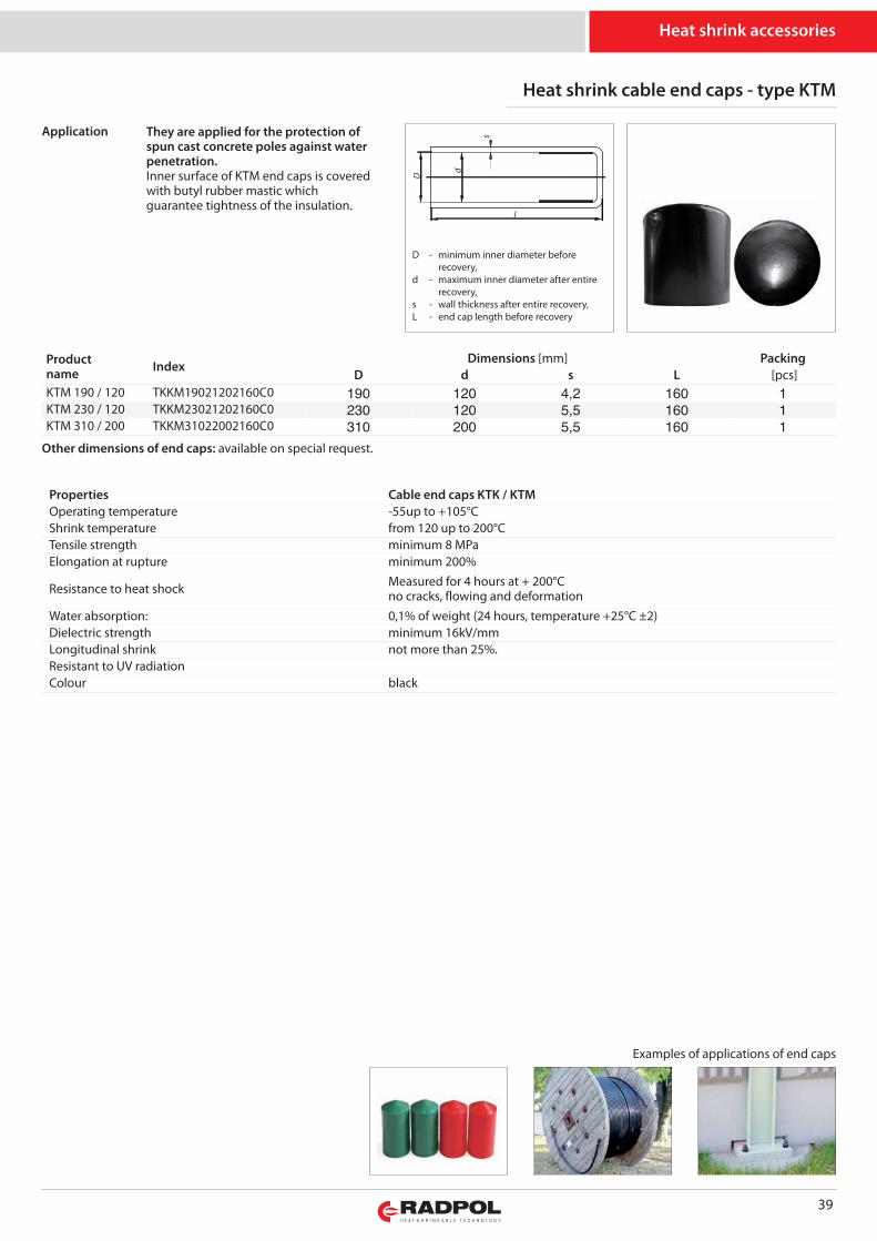
39
They are applied for the protection ofspun cast concrete poles against waterpenetration.Inner surface of KTM end caps is coveredwith butyl rubber mastic whichguarantee tightness of the insulation.
Productname Index
Dimensions [mm] PackingD d s L [pcs]
KTM 190 / 120 TKKM19021202160C0 190 120 4,2 160 1KTM 230 / 120 TKKM23021202160C0 230 120 5,5 160 1KTM 310 / 200 TKKM31022002160C0 310 200 5,5 160 1
Other dimensions of end caps: available on special request.
Heat shrink accessories
D - minimum inner diameter before recovery,
d - maximum inner diameter after entirerecovery,
s - wall thickness after entire recovery,L - end cap length before recovery
Properties Cable end caps KTK / KTMOperating temperature -55up to +105°CShrink temperature from 120 up to 200°CTensile strength mi ni mum 8 MPaElongation at rupture mi ni mum 200%
Resistance to heat shock Measured for 4 hours at + 200°Cno cracks, flowing and deformation
Water absorption: 0,1% of weight (24 hours, temperature +25°C ±2)Dielectric strength mi ni mum 16kV/mmLongitudinal shrink not more than 25%.Resistant to UV radiationColour black
Heat shrink cable end caps - type KTM
Examples of applications of end caps
Application
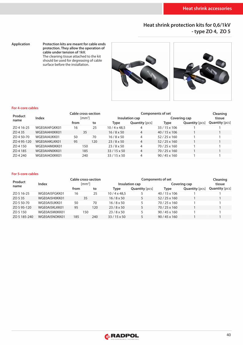
Heat shrink protection kits for 0,6/1kV- type ZO 4, ZO 5
Productname Index
Cable cross-section[mm2]
Components of set Cleaningtissue
Quantity [pcs]Insulation cap Covering cap
from to Type Quantity [pcs] Type Quantity [pcs]ZO 4 16-25 WGE0AI4FGKK01 16 25 10 / 4 x 48,5 4 33 / 15 x 106 1 1ZO 4 35 WGE0AI4H0KK01 35 16 / 8 x 50 4 40 / 15 x 106 1 1ZO 4 50-70 WGE0AI4IJKK01 50 70 16 / 8 x 50 4 52 / 25 x 160 1 1ZO 4 95-120 WGE0AI4KLKK01 95 120 23 / 8 x 50 4 52 / 25 x 160 1 1ZO 4 150 WGE0AI4M0KK01 150 23 / 8 x 50 4 70 / 25 x 160 1 1ZO 4 185 WGE0AI4N0KK01 185 33 / 15 x 50 4 70 / 25 x 160 1 1ZO 4 240 WGE0AI4O0KK01 240 33 / 15 x 50 4 90 / 45 x 160 1 1
For 4-core cables
Productname Index
Cable cross-section[mm2]
Components of set Cleaningtissue
Quantity [pcs]Insulation cap Covering cap
from to Type Quantity [pcs] Type Quantity [pcs]ZO 5 16-25 WGE0AI5FGKK01 16 25 10 / 4 x 48,5 5 40 / 15 x 106 1 1ZO 5 35 WGE0AI5H0KK01 35 16 / 8 x 50 5 52 / 25 x 160 1 1ZO 5 50-70 WGE0AI5IJKK01 50 70 16 / 8 x 50 5 70 / 25 x 160 1 1ZO 5 95-120 WGE0AI5KLKK01 95 120 23 / 8 x 50 5 70 / 25 x 160 1 1ZO 5 150 WGE0AI5M0KK01 150 23 / 8 x 50 5 90 / 45 x 160 1 1ZO 5 185-240 WGE0AI5NOKK01 185 240 33 / 15 x 50 5 90 / 45 x 160 1 1
For 5-core cables
40
Heat shrink accessories
Protection kits are meant for cable endsprotection. They allow the operation ofcable under tension of 1kV.The cleaning tissue attached to the kitshould be used for degreasing of cablesurface before the installation.
Application
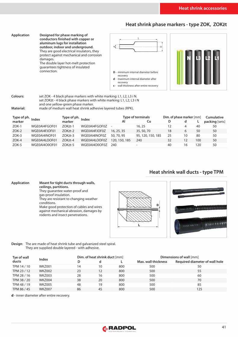
Heat shrink phase markers - type ZOK, ZOKżt
Type of ph.marker Index Type of ph.
marker IndexType of terminals Dim. of phase marker [mm] Cumulative
packing [sets]Al Cu D d LZOK-1 WGE0AI4FGOF01 ZOKżt-1 WGE0AI4FGOF0Z - 16, 25 12 4 40 50ZOK-2 WGE0AI4FJOF01 ZOKżt-2 WGE0AI4FJOF0Z 16, 25, 35 35, 50, 70 18 6 50 50ZOK-3 WGE0AI4INOF01 ZOKżt-3 WGE0AI4INOF0Z 50, 70, 95 95, 120, 150, 185 25 10 80 50ZOK-4 WGE0AI4LOOF01 ZOKżt-4 WGE0AI4LOOF0Z 120, 150, 185 240 32 12 100 50ZOK-5 WGE0AI4O0OF01 ZOKżt-5 WGE0AI4O0OF0Z 240 - 40 16 120 50
Dd
L
41
Heat shrink wall ducts - type TPM
Tye of wallducts Index
Dim. of heat shrink duct [mm] Dimensions of wall [mm]D d L Max. wall thickness Required diameter of wall hole
TPM 14 / 10 WKZ001 14 10 800 500 50TPM 23 / 12 WKZ002 23 12 800 500 55TPM 28 / 16 WKZ003 28 16 800 500 60TPM 38 / 20 WKZ004 38 20 800 500 70TPM 48 / 19 WKZ005 48 19 800 500 85TPM 86 / 45 WKZ007 86 45 800 500 125
Heat shrink accessories
Colours: set ZOK - 4 black phase markers with white marking: L1, L2, L3 i N.set ZOKżt - 4 black phase markers with white marking: L1, L2, L3 i Nand one yellow-green phase marker.
Ma te rial: made of medium wall heat shrink adhesive layered tubes (RPK).
Design: The are made of heat shrink tube and galvanized steel spiral. They are supplied double layered - with adhesive.
Designed for phase marking ofconductors finished with copper oraluminum lugs for installationoutdoor, indoor and underground.They are good electrical insulators, theyprotect against mechanical and corrosiondamages.The double layer hot-melt protectionguarantees tightness of insulatedconnection.
Application
Meant for tight ducts through walls,ceilings, partitions.They guarantee water-proof andgas-proof insulation. They are resistant to changing weatherconditions.Make good protection of cables and wiresagainst mechanical abrasion, damages byrodents and insect penetrations.
Application
d - inner diameter after entire recovery.
D - minimum internal diameter before recoveryd - maximum internal diameter after recoverys - wall thickness after entire recovery
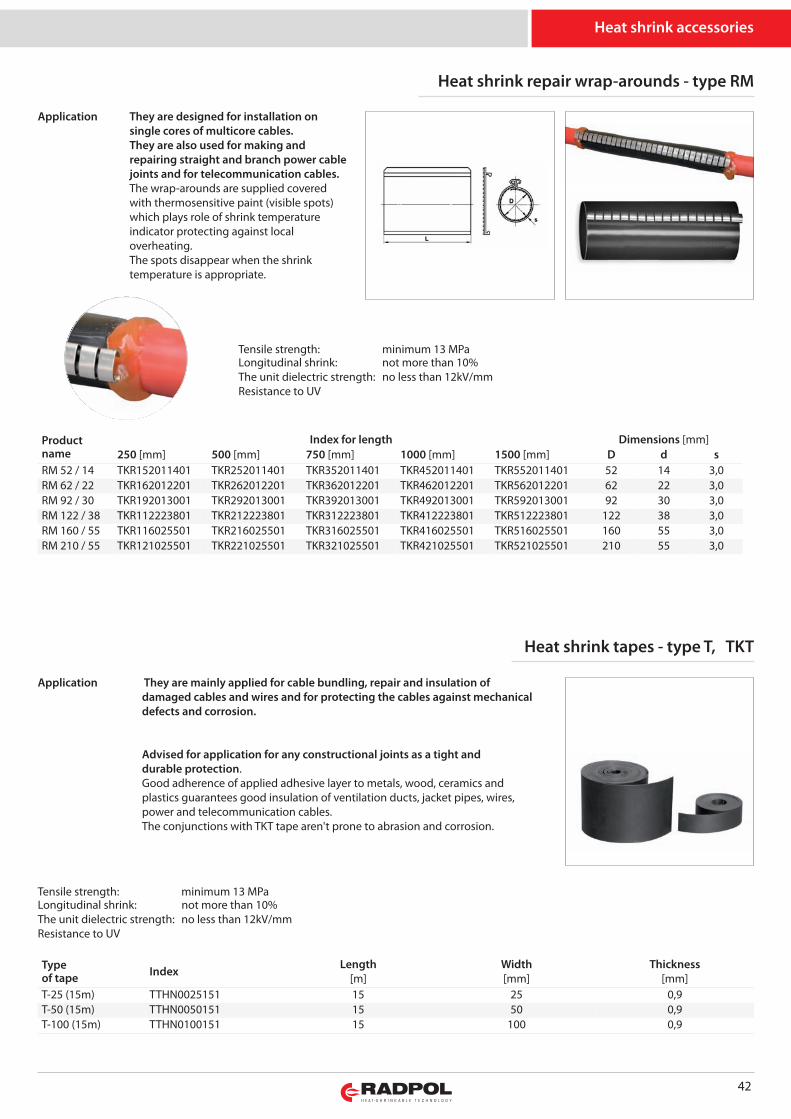
Heat shrink repair wrap-arounds - type RM
Productname
Index for length Dimensions [mm]250 [mm] 500 [mm] 750 [mm] 1000 [mm] 1500 [mm] D d s
RM 52 / 14 TKR152011401 TKR252011401 TKR352011401 TKR452011401 TKR552011401 52 14 3,0RM 62 / 22 TKR162012201 TKR262012201 TKR362012201 TKR462012201 TKR562012201 62 22 3,0RM 92 / 30 TKR192013001 TKR292013001 TKR392013001 TKR492013001 TKR592013001 92 30 3,0RM 122 / 38 TKR112223801 TKR212223801 TKR312223801 TKR412223801 TKR512223801 122 38 3,0RM 160 / 55 TKR116025501 TKR216025501 TKR316025501 TKR416025501 TKR516025501 160 55 3,0RM 210 / 55 TKR121025501 TKR221025501 TKR321025501 TKR421025501 TKR521025501 210 55 3,0
42
Heat shrink tapes - type T, TKT
Typeof tape Index Length
[m]Width[mm]
Thickness[mm]
T-25 (15m) TTHN0025151 15 25 0,9T-50 (15m) TTHN0050151 15 50 0,9T-100 (15m) TTHN0100151 15 100 0,9
Heat shrink accessories
Tensile strength: mi ni mum 13 MPaLongitudinal shrink: not more than 10%The unit dielectric strength: no less than 12kV/mmResistance to UV
Tensile strength: mi ni mum 13 MPaLongitudinal shrink: not more than 10%The unit dielectric strength: no less than 12kV/mmResistance to UV
They are designed for installation onsingle cores of multicore cables.They are also used for making andrepairing straight and branch power cablejoints and for telecommunication cables.The wrap-arounds are supplied coveredwith thermosensitive paint (visible spots)which plays role of shrink temperatureindicator protecting against localoverheating.The spots disappear when the shrinktemperature is appropriate.
Application
They are mainly applied for cable bundling, repair and insulation ofdamaged cables and wires and for protecting the cables against mechanicaldefects and corrosion.
Advised for application for any constructional joints as a tight anddurable protection. Good adherence of applied adhesive layer to metals, wood, ceramics andplastics guarantees good insulation of ventilation ducts, jacket pipes, wires,power and telecommunication cables. The conjunctions with TKT tape aren't prone to abrasion and corrosion.
Application
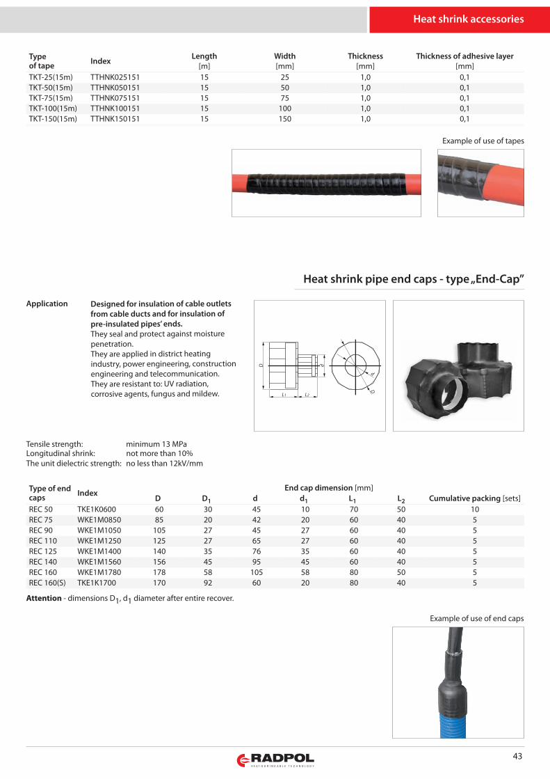
43
Typeof tape Index Length
[m]Width[mm]
Thickness[mm]
Thickness of adhesive layer[mm]
TKT-25(15m) TTHNK025151 15 25 1,0 0,1TKT-50(15m) TTHNK050151 15 50 1,0 0,1TKT-75(15m) TTHNK075151 15 75 1,0 0,1TKT-100(15m) TTHNK100151 15 100 1,0 0,1TKT-150(15m) TTHNK150151 15 150 1,0 0,1
Heat shrink pipe end caps - type „End-Cap”
Type of endcaps Index
End cap dimension [mm]D D1 d d1 L1 L2 Cumulative packing [sets]
REC 50 TKE1K0600 60 30 45 10 70 50 10REC 75 WKE1M0850 85 20 42 20 60 40 5REC 90 WKE1M1050 105 27 45 27 60 40 5REC 110 WKE1M1250 125 27 65 27 60 40 5REC 125 WKE1M1400 140 35 76 35 60 40 5REC 140 WKE1M1560 156 45 95 45 60 40 5REC 160 WKE1M1780 178 58 105 58 80 50 5REC 160(S) TKE1K1700 170 92 60 20 80 40 5
dD
L1 L2
d
D
Attention - dimensions D1, d1 diameter after entire recover.
Heat shrink accessories
Example of use of tapes
Example of use of end caps
Tensile strength: mi ni mum 13 MPaLongitudinal shrink: not more than 10%The unit dielectric strength: no less than 12kV/mm
Designed for insulation of cable outletsfrom cable ducts and for insulation ofpre-insulated pipes’ ends.They seal and protect against moisturepenetration.They are applied in district heatingindustry, power engineering, constructionengineering and telecommunication.They are resistant to: UV radiation,corrosive agents, fungus and mildew.
Application
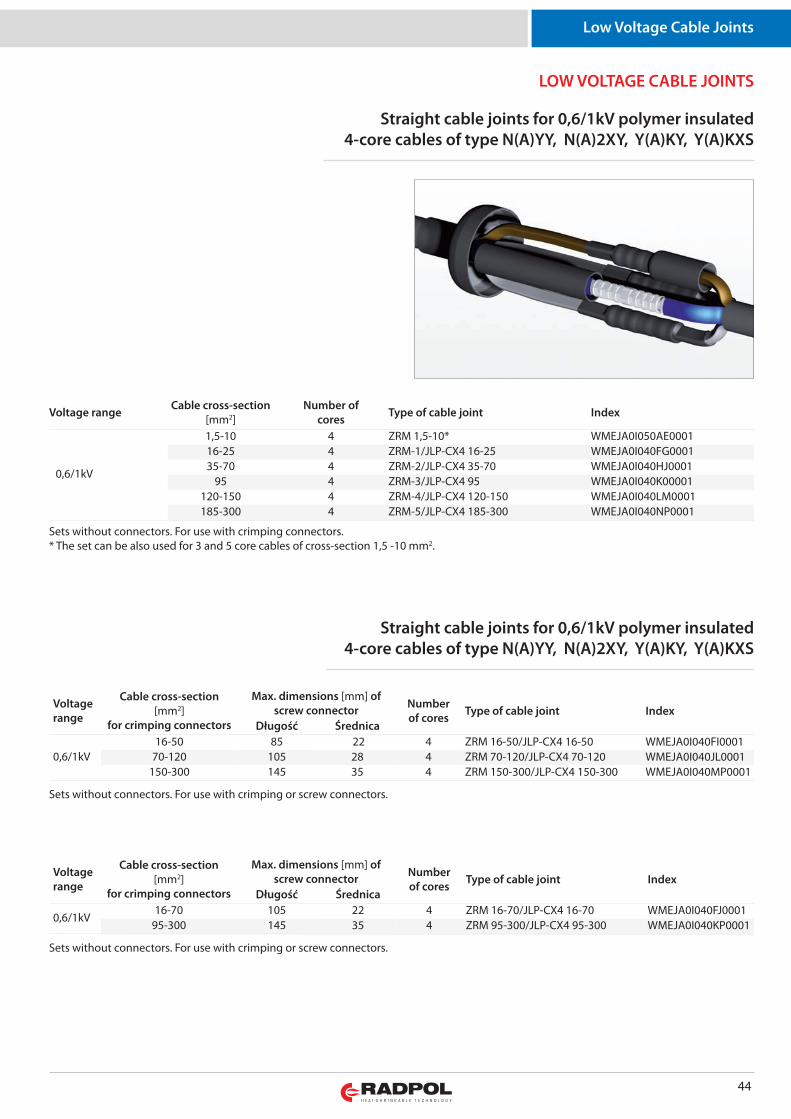
44
LOW VOLTAGE CABLE JOINTS
Low Voltage Cable Joints
Voltage range Cable cross-section[mm2]
Number ofcores Type of cable joint Index
0,6/1kV
1,5-10 4 ZRM 1,5-10* WMEJA0I050AE000116-25 4 ZRM-1/JLP-CX4 16-25 WMEJA0I040FG000135-70 4 ZRM-2/JLP-CX4 35-70 WMEJA0I040HJ0001
95 4 ZRM-3/JLP-CX4 95 WMEJA0I040K00001120-150 4 ZRM-4/JLP-CX4 120-150 WMEJA0I040LM0001185-300 4 ZRM-5/JLP-CX4 185-300 WMEJA0I040NP0001
Straight cable joints for 0,6/1kV polymer insulated4-core cables of type N(A)YY, N(A)2XY, Y(A)KY, Y(A)KXS
Sets without connectors. For use with crimping connectors.* The set can be also used for 3 and 5 core cables of cross-section 1,5 -10 mm2.
Sets without connectors. For use with crimping or screw connectors.
Sets without connectors. For use with crimping or screw connectors.
Straight cable joints for 0,6/1kV polymer insulated4-core cables of type N(A)YY, N(A)2XY, Y(A)KY, Y(A)KXS
Voltagerange
Cable cross-section[mm2]
for crimping connectors
Max. dimensions [mm] ofscrew connector Number
of cores Type of cable joint IndexDługość Średnica
0,6/1kV16-50 85 22 4 ZRM 16-50/JLP-CX4 16-50 WMEJA0I040FI0001
70-120 105 28 4 ZRM 70-120/JLP-CX4 70-120 WMEJA0I040JL0001150-300 145 35 4 ZRM 150-300/JLP-CX4 150-300 WMEJA0I040MP0001
Voltagerange
Cable cross-section[mm2]
for crimping connectors
Max. dimensions [mm] ofscrew connector Number
of cores Type of cable joint IndexDługość Średnica
0,6/1kV16-70 105 22 4 ZRM 16-70/JLP-CX4 16-70 WMEJA0I040FJ0001
95-300 145 35 4 ZRM 95-300/JLP-CX4 95-300 WMEJA0I040KP0001
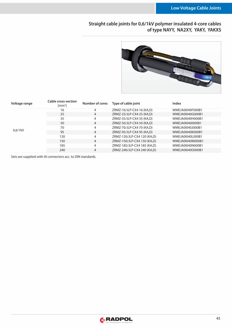
45
Low Voltage Cable Joints
Voltage range Cable cross-section[mm2] Number of cores Type of cable joint Index
0,6/1kV
16 4 ZRMZ-16/JLP-CX4 16 (KA,D) WMEJA0I040F000B125 4 ZRMZ-25/JLP-CX4 25 (KA,D) WMEJA0I040G000B135 4 ZRMZ-35/JLP-CX4 35 (KA,D) WMEJA0I040H000B150 4 ZRMZ-50/JLP-CX4 50 (KA,D) WMEJA0I040I000B170 4 ZRMZ-70/JLP-CX4 70 (KA,D) WMEJA0I040J000B195 4 ZRMZ-95/JLP-CX4 95 (KA,D) WMEJA0I040K000B1
120 4 ZRMZ-120/JLP-CX4 120 (KA,D) WMEJA0I040L000B1150 4 ZRMZ-150/JLP-CX4 150 (KA,D) WMEJA0I040M000B1185 4 ZRMZ-185/JLP-CX4 185 (KA,D) WMEJA0I040N000B1240 4 ZRMZ-240/JLP-CX4 240 (KA,D) WMEJA0I040O000B1
Straight cable joints for 0,6/1kV polymer insulated 4-core cablesof type NAYY, NA2XY, YAKY, YAKXS
Sets are supplied with Al connectors acc. to DIN standards.
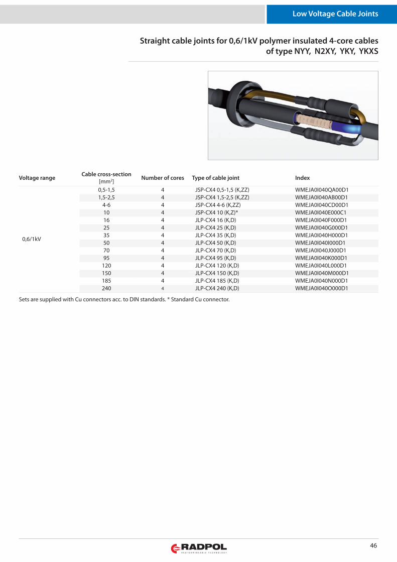
46
Low Voltage Cable Joints
Voltage range Cable cross-section[mm2] Number of cores Type of cable joint Index
0,6/1kV
0,5-1,5 4 JSP-CX4 0,5-1,5 (K,ZZ) WMEJA0I040QA00D11,5-2,5 4 JSP-CX4 1,5-2,5 (K,ZZ) WMEJA0I040AB00D1
4-6 4 JSP-CX4 4-6 (K,ZZ) WMEJA0I040CD00D110 4 JSP-CX4 10 (K,Z)* WMEJA0I040E000C116 4 JLP-CX4 16 (K,D) WMEJA0I040F000D125 4 JLP-CX4 25 (K,D) WMEJA0I040G000D135 4 JLP-CX4 35 (K,D) WMEJA0I040H000D150 4 JLP-CX4 50 (K,D) WMEJA0I040I000D170 4 JLP-CX4 70 (K,D) WMEJA0I040J000D195 4 JLP-CX4 95 (K,D) WMEJA0I040K000D1
120 4 JLP-CX4 120 (K,D) WMEJA0I040L000D1150 4 JLP-CX4 150 (K,D) WMEJA0I040M000D1185 4 JLP-CX4 185 (K,D) WMEJA0I040N000D1240 4 JLP-CX4 240 (K,D) WMEJA0I040O000D1
Straight cable joints for 0,6/1kV polymer insulated 4-core cablesof type NYY, N2XY, YKY, YKXS
Sets are supplied with Cu connectors acc. to DIN standards. * Standard Cu connector.
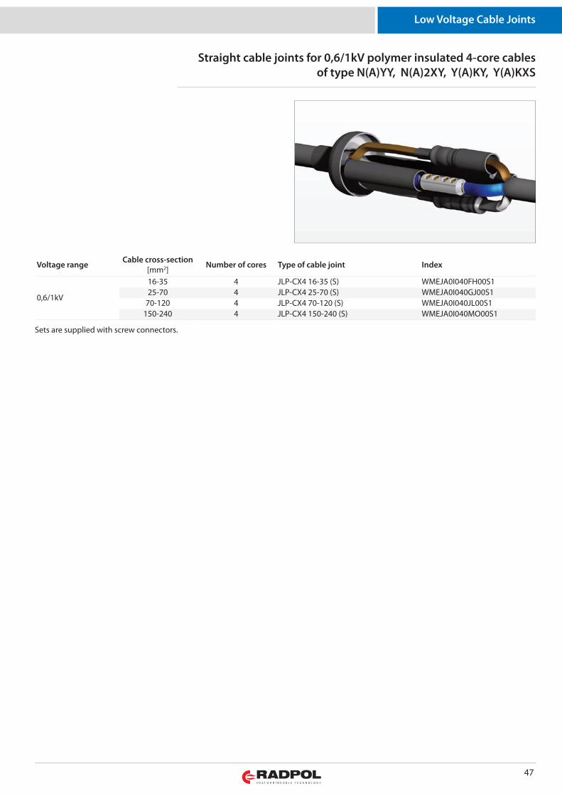
47
Low Voltage Cable Joints
Voltage range Cable cross-section[mm2] Number of cores Type of cable joint Index
0,6/1kV
16-35 4 JLP-CX4 16-35 (S) WMEJA0I040FH00S125-70 4 JLP-CX4 25-70 (S) WMEJA0I040GJ00S1
70-120 4 JLP-CX4 70-120 (S) WMEJA0I040JL00S1150-240 4 JLP-CX4 150-240 (S) WMEJA0I040MO00S1
Straight cable joints for 0,6/1kV polymer insulated 4-core cablesof type N(A)YY, N(A)2XY, Y(A)KY, Y(A)KXS
Sets are supplied with screw connectors.
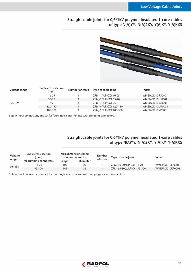
48
Low Voltage Cable Joints
Voltage range Cable cross-section[mm2] Number of cores Type of cable joint Index
0,6/1kV
16-25 1 ZRMj-1/JLP-CX1 16-25 WMEJA0I010FG000135-70 1 ZRMj-2/JLP-CX1 35-70 WMEJA0I010HJ0001
95 1 ZRMj-3/JLP-CX1 95 WMEJA0I010K00001120-150 1 ZRMj-4/JLP-CX1 120-150 WMEJA0I010LM0001185-300 1 ZRMj-5/JLP-CX1 185-300 WMEJA0I010NP0001
Straight cable joints for 0,6/1kV polymer insulated 1-core cablesof type N(A)YY, N(A)2XY, Y(A)KY, Y(A)KXS
Sets without connectors, one set for four single cores. For use with crimping connectors.
Straight cable joints for 0,6/1kV polymer insulated 1-core cablesof type N(A)YY, N(A)2XY, Y(A)KY, Y(A)KXS
Sets without connectors, one set for four single cores. For use with crimping or screw connectors.
Voltagerange
Cable cross-section[mm2]
for crimping connectors
Max. dimensions [mm]of screw connector Number
of cores Type of cable joint IndexLength Diameter
0,6/1kV16-70 105 22 1 ZRMj 16-70/JLP-CX1 16-70 WMEJA0I010FJ0001
95-300 145 35 1 ZRMj 95-300/JLP-CX1 95-300 WMEJA0I010KP0001
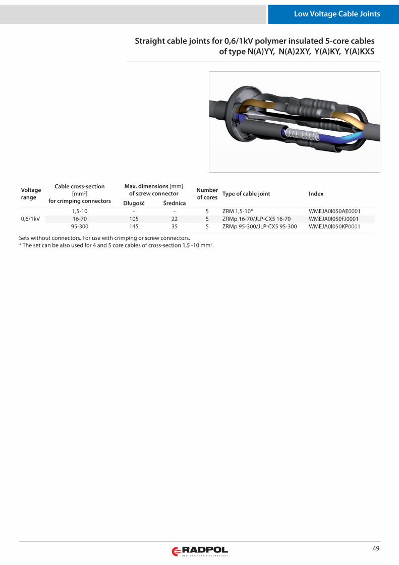
49
Low Voltage Cable Joints
Straight cable joints for 0,6/1kV polymer insulated 5-core cablesof type N(A)YY, N(A)2XY, Y(A)KY, Y(A)KXS
Sets without connectors. For use with crimping or screw connectors.* The set can be also used for 4 and 5 core cables of cross-section 1,5 -10 mm2.
Voltagerange
Cable cross-section[mm2]
for crimping connectors
Max. dimensions [mm]of screw connector Number
of cores Type of cable joint Index
Długość Średnica
0,6/1kV1,5-10 - - 5 ZRM 1,5-10* WMEJA0I050AE000116-70 105 22 5 ZRMp 16-70/JLP-CX5 16-70 WMEJA0I050FJ0001
95-300 145 35 5 ZRMp 95-300/JLP-CX5 95-300 WMEJA0I050KP0001
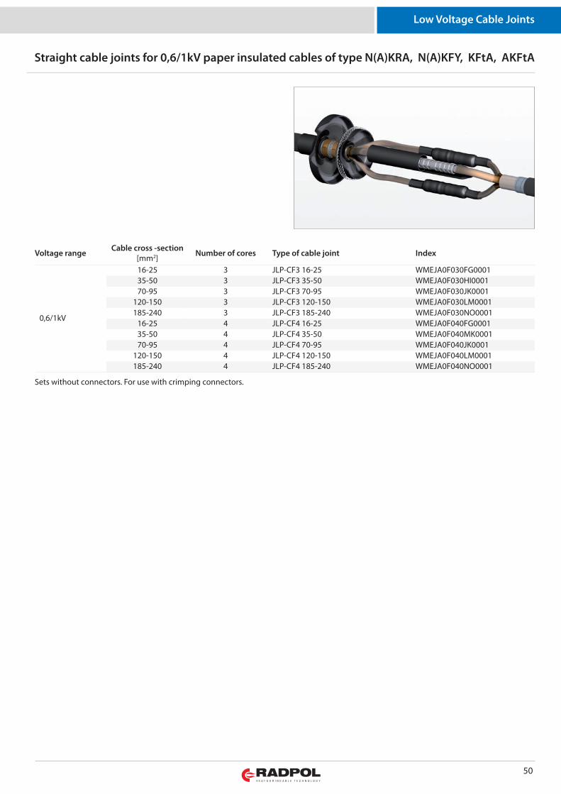
50
Low Voltage Cable Joints
Straight cable joints for 0,6/1kV paper insulated cables of type N(A)KRA, N(A)KFY, KFtA, AKFtA
Sets without connectors. For use with crimping connectors.
Voltage range Cable cross -section[mm2] Number of cores Type of cable joint Index
0,6/1kV
16-25 3 JLP-CF3 16-25 WMEJA0F030FG000135-50 3 JLP-CF3 35-50 WMEJA0F030HI000170-95 3 JLP-CF3 70-95 WMEJA0F030JK0001
120-150 3 JLP-CF3 120-150 WMEJA0F030LM0001185-240 3 JLP-CF3 185-240 WMEJA0F030NO0001
16-25 4 JLP-CF4 16-25 WMEJA0F040FG000135-50 4 JLP-CF4 35-50 WMEJA0F040MK000170-95 4 JLP-CF4 70-95 WMEJA0F040JK0001
120-150 4 JLP-CF4 120-150 WMEJA0F040LM0001185-240 4 JLP-CF4 185-240 WMEJA0F040NO0001
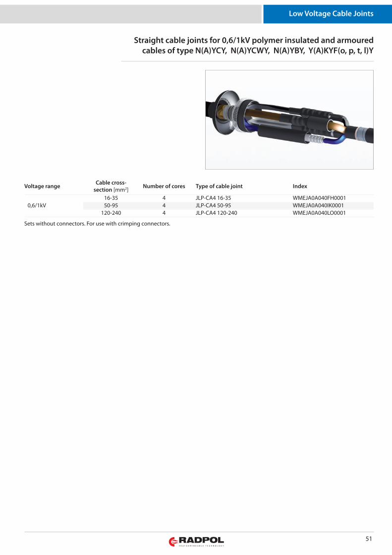
51
Low Voltage Cable Joints
Straight cable joints for 0,6/1kV polymer insulated and armouredcables of type N(A)YCY, N(A)YCWY, N(A)YBY, Y(A)KYF(o, p, t, l)Y
Sets without connectors. For use with crimping connectors.
Voltage range Cable cross-section [mm2] Number of cores Type of cable joint Index
0,6/1kV16-35 4 JLP-CA4 16-35 WMEJA0A040FH000150-95 4 JLP-CA4 50-95 WMEJA0A040IK0001
120-240 4 JLP-CA4 120-240 WMEJA0A040LO0001
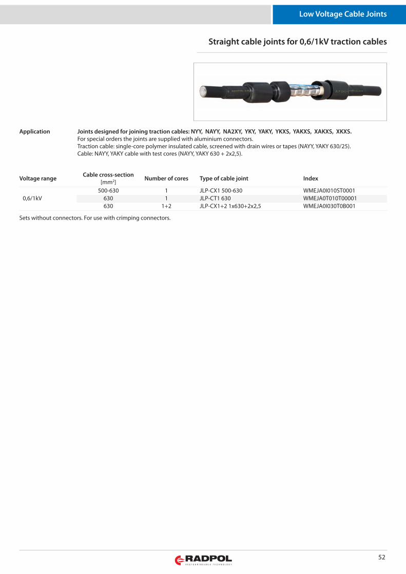
52
Low Voltage Cable Joints
Straight cable joints for 0,6/1kV traction cables
Sets without connectors. For use with crimping connectors.
Voltage range Cable cross-section[mm2] Number of cores Type of cable joint Index
0,6/1kV500-630 1 JLP-CX1 500-630 WMEJA0I010ST0001
630 1 JLP-CT1 630 WMEJA0T010T00001630 1+2 JLP-CX1+2 1x630+2x2,5 WMEJA0I030T0B001
Joints designed for joining traction cables: NYY, NAYY, NA2XY, YKY, YAKY, YKXS, YAKXS, XAKXS, XKXS.For special orders the joints are supplied with aluminium connectors.Traction cable: single-core polymer insulated cable, screened with drain wires or tapes (NAYY, YAKY 630/25).Cable: NAYY, YAKY cable with test cores (NAYY, YAKY 630 + 2x2,5).
Application
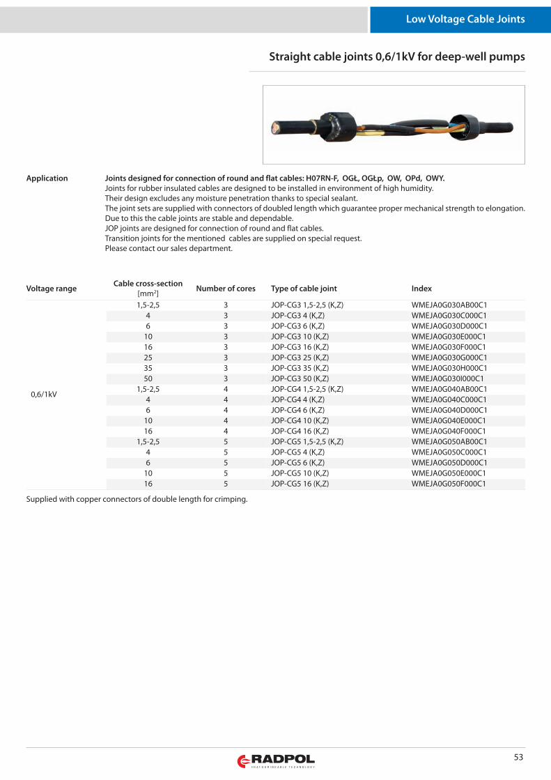
53
Low Voltage Cable Joints
Straight cable joints 0,6/1kV for deep-well pumps
Supplied with copper connectors of double length for crimping.
Voltage range Cable cross-section[mm2] Number of cores Type of cable joint Index
0,6/1kV
1,5-2,5 3 JOP-CG3 1,5-2,5 (K,Z) WMEJA0G030AB00C14 3 JOP-CG3 4 (K,Z) WMEJA0G030C000C16 3 JOP-CG3 6 (K,Z) WMEJA0G030D000C1
10 3 JOP-CG3 10 (K,Z) WMEJA0G030E000C116 3 JOP-CG3 16 (K,Z) WMEJA0G030F000C125 3 JOP-CG3 25 (K,Z) WMEJA0G030G000C135 3 JOP-CG3 35 (K,Z) WMEJA0G030H000C150 3 JOP-CG3 50 (K,Z) WMEJA0G030I000C1
1,5-2,5 4 JOP-CG4 1,5-2,5 (K,Z) WMEJA0G040AB00C14 4 JOP-CG4 4 (K,Z) WMEJA0G040C000C16 4 JOP-CG4 6 (K,Z) WMEJA0G040D000C1
10 4 JOP-CG4 10 (K,Z) WMEJA0G040E000C116 4 JOP-CG4 16 (K,Z) WMEJA0G040F000C1
1,5-2,5 5 JOP-CG5 1,5-2,5 (K,Z) WMEJA0G050AB00C14 5 JOP-CG5 4 (K,Z) WMEJA0G050C000C16 5 JOP-CG5 6 (K,Z) WMEJA0G050D000C1
10 5 JOP-CG5 10 (K,Z) WMEJA0G050E000C116 5 JOP-CG5 16 (K,Z) WMEJA0G050F000C1
Joints designed for connection of round and flat cables: H07RN-F, OGŁ, OGŁp, OW, OPd, OWY.Joints for rubber insulated cables are designed to be installed in environment of high humidity. Their design excludes any moisture penetration thanks to special sealant. The joint sets are supplied with connectors of doubled length which guarantee proper mechanical strength to elongation.Due to this the cable joints are stable and dependable.JOP joints are designed for connection of round and flat cables.Transition joints for the mentioned cables are supplied on special request.Please contact our sales department.
Application
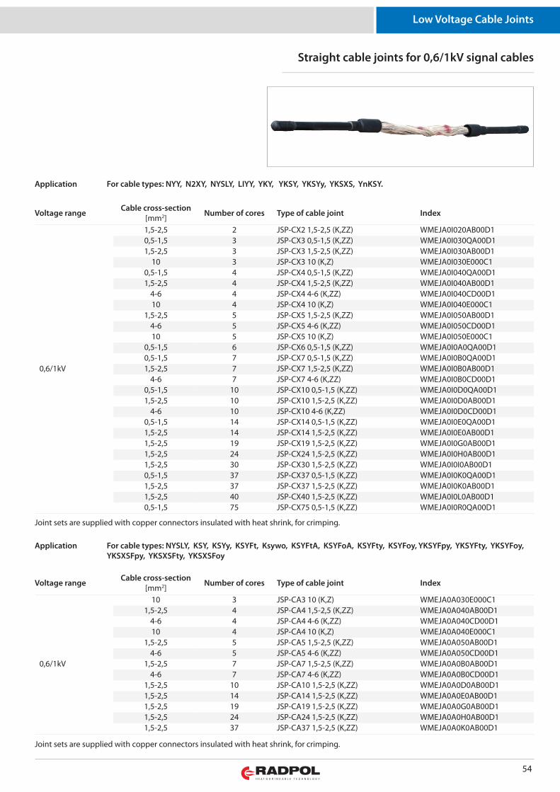
54
Low Voltage Cable Joints
Straight cable joints for 0,6/1kV signal cables
Joint sets are supplied with copper connectors insulated with heat shrink, for crimping.
For cable types: NYY, N2XY, NYSLY, LIYY, YKY, YKSY, YKSYy, YKSXS, YnKSY.Application
Voltage range Cable cross-section[mm2] Number of cores Type of cable joint Index
0,6/1kV
1,5-2,5 2 JSP-CX2 1,5-2,5 (K,ZZ) WMEJA0I020AB00D10,5-1,5 3 JSP-CX3 0,5-1,5 (K,ZZ) WMEJA0I030QA00D11,5-2,5 3 JSP-CX3 1,5-2,5 (K,ZZ) WMEJA0I030AB00D1
10 3 JSP-CX3 10 (K,Z) WMEJA0I030E000C10,5-1,5 4 JSP-CX4 0,5-1,5 (K,ZZ) WMEJA0I040QA00D11,5-2,5 4 JSP-CX4 1,5-2,5 (K,ZZ) WMEJA0I040AB00D1
4-6 4 JSP-CX4 4-6 (K,ZZ) WMEJA0I040CD00D110 4 JSP-CX4 10 (K,Z) WMEJA0I040E000C1
1,5-2,5 5 JSP-CX5 1,5-2,5 (K,ZZ) WMEJA0I050AB00D14-6 5 JSP-CX5 4-6 (K,ZZ) WMEJA0I050CD00D110 5 JSP-CX5 10 (K,Z) WMEJA0I050E000C1
0,5-1,5 6 JSP-CX6 0,5-1,5 (K,ZZ) WMEJA0I0A0QA00D10,5-1,5 7 JSP-CX7 0,5-1,5 (K,ZZ) WMEJA0I0B0QA00D11,5-2,5 7 JSP-CX7 1,5-2,5 (K,ZZ) WMEJA0I0B0AB00D1
4-6 7 JSP-CX7 4-6 (K,ZZ) WMEJA0I0B0CD00D10,5-1,5 10 JSP-CX10 0,5-1,5 (K,ZZ) WMEJA0I0D0QA00D11,5-2,5 10 JSP-CX10 1,5-2,5 (K,ZZ) WMEJA0I0D0AB00D1
4-6 10 JSP-CX10 4-6 (K,ZZ) WMEJA0I0D0CD00D10,5-1,5 14 JSP-CX14 0,5-1,5 (K,ZZ) WMEJA0I0E0QA00D11,5-2,5 14 JSP-CX14 1,5-2,5 (K,ZZ) WMEJA0I0E0AB00D11,5-2,5 19 JSP-CX19 1,5-2,5 (K,ZZ) WMEJA0I0G0AB00D11,5-2,5 24 JSP-CX24 1,5-2,5 (K,ZZ) WMEJA0I0H0AB00D11,5-2,5 30 JSP-CX30 1,5-2,5 (K,ZZ) WMEJA0I0I0AB00D10,5-1,5 37 JSP-CX37 0,5-1,5 (K,ZZ) WMEJA0I0K0QA00D11,5-2,5 37 JSP-CX37 1,5-2,5 (K,ZZ) WMEJA0I0K0AB00D11,5-2,5 40 JSP-CX40 1,5-2,5 (K,ZZ) WMEJA0I0L0AB00D10,5-1,5 75 JSP-CX75 0,5-1,5 (K,ZZ) WMEJA0I0R0QA00D1
Voltage range Cable cross-section[mm2] Number of cores Type of cable joint Index
0,6/1kV
10 3 JSP-CA3 10 (K,Z) WMEJA0A030E000C11,5-2,5 4 JSP-CA4 1,5-2,5 (K,ZZ) WMEJA0A040AB00D1
4-6 4 JSP-CA4 4-6 (K,ZZ) WMEJA0A040CD00D110 4 JSP-CA4 10 (K,Z) WMEJA0A040E000C1
1,5-2,5 5 JSP-CA5 1,5-2,5 (K,ZZ) WMEJA0A050AB00D14-6 5 JSP-CA5 4-6 (K,ZZ) WMEJA0A050CD00D1
1,5-2,5 7 JSP-CA7 1,5-2,5 (K,ZZ) WMEJA0A0B0AB00D14-6 7 JSP-CA7 4-6 (K,ZZ) WMEJA0A0B0CD00D1
1,5-2,5 10 JSP-CA10 1,5-2,5 (K,ZZ) WMEJA0A0D0AB00D11,5-2,5 14 JSP-CA14 1,5-2,5 (K,ZZ) WMEJA0A0E0AB00D11,5-2,5 19 JSP-CA19 1,5-2,5 (K,ZZ) WMEJA0A0G0AB00D11,5-2,5 24 JSP-CA24 1,5-2,5 (K,ZZ) WMEJA0A0H0AB00D11,5-2,5 37 JSP-CA37 1,5-2,5 (K,ZZ) WMEJA0A0K0AB00D1
For cable types: NYSLY, KSY, KSYy, KSYFt, Ksywo, KSYFtA, KSYFoA, KSYFty, KSYFoy, YKSYFpy, YKSYFty, YKSYFoy,YKSXSFpy, YKSXSFty, YKSXSFoy
Application
Joint sets are supplied with copper connectors insulated with heat shrink, for crimping.
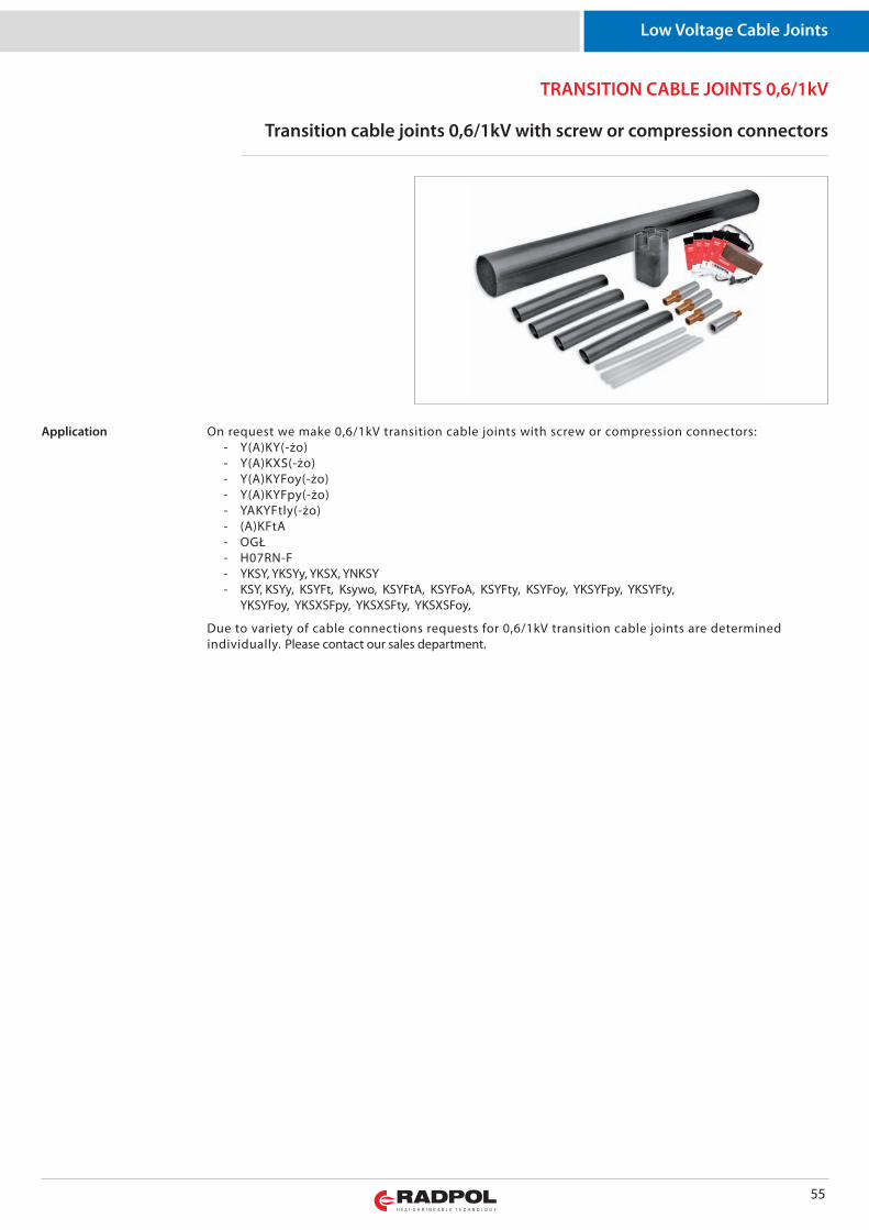
55
TRANSITION CABLE JOINTS 0,6/1kV
Low Voltage Cable Joints
Transition cable joints 0,6/1kV with screw or compression connectors
On request we make 0,6/1kV transition cable joints with screw or compression connectors: - Y(A)KY(-żo) - Y(A)KXS(-żo) - Y(A)KYFoy(-żo) - Y(A)KYFpy(-żo) - YAKYFtly(-żo) - (A)KFtA - OGŁ - H07RN-F - YKSY, YKSYy, YKSX, YNKSY - KSY, KSYy, KSYFt, Ksywo, KSYFtA, KSYFoA, KSYFty, KSYFoy, YKSYFpy, YKSYFty, YKSYFoy, YKSXSFpy, YKSXSFty, YKSXSFoy,
Due to variety of cable connections requests for 0,6/1kV transition cable joints are determinedindividually. Please contact our sales department.
Application
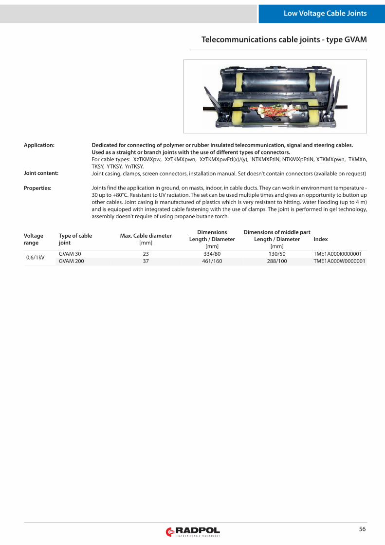
56
Low Voltage Cable Joints
Telecommunications cable joints - type GVAM
Dedicated for connecting of polymer or rubber insulated telecommunication, signal and steering cables.Used as a straight or branch joints with the use of different types of connectors. For cable types: XzTK MXpw, XzTK MXpwn, XzTK MXpw Ftl(x)/(y), NTK MXFtlN, NTK MXp FtlN, XTK MXpwn, TKMXn,TKSY, YTK SY, YnTK SY. Joint casing, clamps, screen connectors, installation manual. Set doesn't contain connectors (available on request)
Joints find the application in ground, on masts, indoor, in cable ducts. They can work in environment temperature -30 up to +80°C. Resistant to UV radiation. The set can be used multiple times and gives an opportunity to button upother cables. Joint casing is manufactured of plastics which is very resistant to hitting. water flooding (up to 4 m)and is equipped with integrated cable fastening with the use of clamps. The joint is performed in gel technology,assembly doesn't require of using propane butane torch.
Application:
Joint content:
Properties:
Voltagerange
Type of cablejoint
Max. Cable diameter[mm]
DimensionsLength / Diameter
[mm]
Dimensions of middle part Length / Diameter
[mm]Index
0,6/1kVGVAM 30 23 334/80 130/50 TME1A000I0000001GVAM 200 37 461/160 288/100 TME1A000W0000001
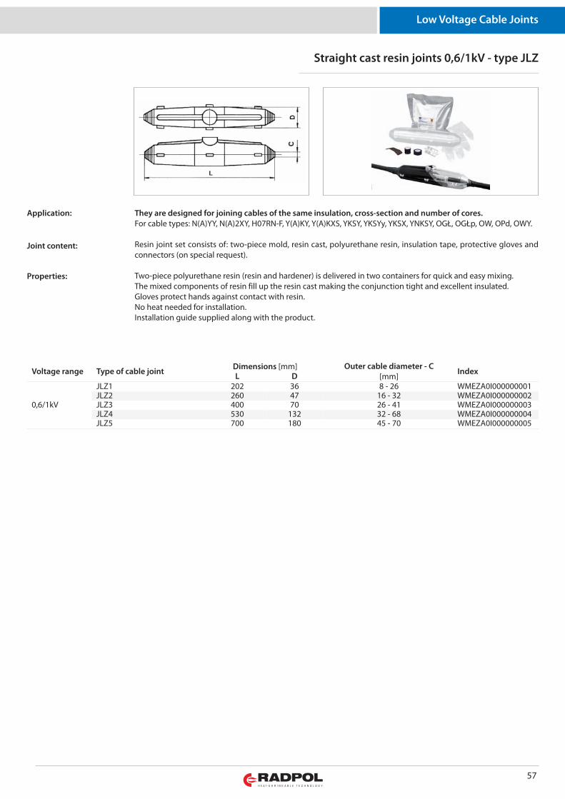
57
Low Voltage Cable Joints
Straight cast resin joints 0,6/1kV - type JLZ
They are designed for joining cables of the same insulation, cross-section and number of cores.For cable types: N(A)YY, N(A)2XY, H07RN-F, Y(A)KY, Y(A)KXS, YK SY, YK SYy, YKSX, YNK SY, OGŁ, OGŁp, OW, OPd, OWY.
Resin joint set consists of: two-piece mold, resin cast, polyurethane resin, insulation tape, protective gloves andconnectors (on special request).
Two-piece polyurethane resin (resin and hardener) is delivered in two containers for quick and easy mixing. The mixed components of resin fill up the resin cast making the conjunction tight and excellent insulated. Gloves protect hands against contact with resin.No heat needed for installation.Installation guide supplied along with the product.
Application:
Joint content:
Properties:
Voltage range Type of cable joint Dimensions [mm] Outer cable diameter - C[mm] IndexL D
0,6/1kV
JLZ1 202 36 8 - 26 WMEZA0I000000001JLZ2 260 47 16 - 32 WMEZA0I000000002JLZ3 400 70 26 - 41 WMEZA0I000000003JLZ4 530 132 32 - 68 WMEZA0I000000004JLZ5 700 180 45 - 70 WMEZA0I000000005
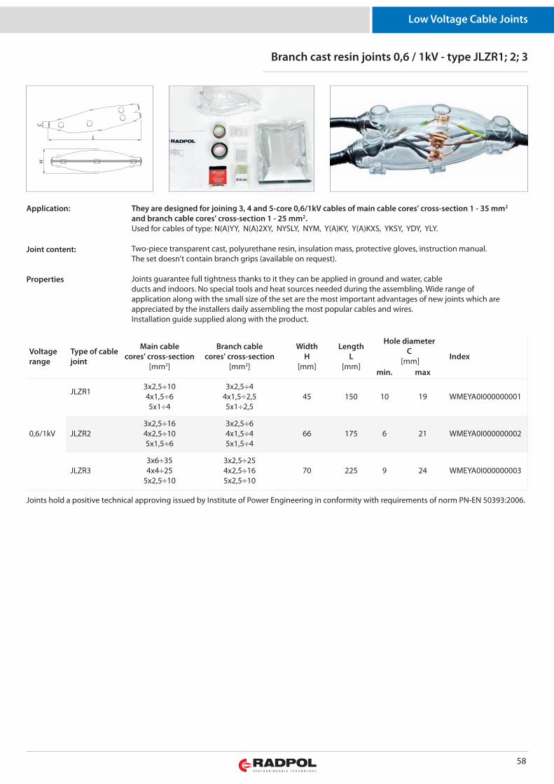
58
Low Voltage Cable Joints
Branch cast resin joints 0,6 / 1kV - type JLZR1; 2; 3
They are designed for joining 3, 4 and 5-core 0,6/1kV cables of main cable cores' cross-section 1 - 35 mm2
and branch cable cores' cross-section 1 - 25 mm2.Used for cables of type: N(A)YY, N(A)2XY, NYSLY, NYM, Y(A)KY, Y(A)KXS, YK SY, YDY, YLY.
Two-piece transparent cast, polyurethane resin, insulation mass, protective gloves, instruction manual.The set doesn't contain branch grips (available on request).
Joints guarantee full tightness thanks to it they can be applied in ground and water, cableducts and indoors. No special tools and heat sources needed during the assembling. Wide range ofapplication along with the small size of the set are the most important advantages of new joints which areappreciated by the installers daily assembling the most popular cables and wires.Installation guide supplied along with the product.
Application:
Joint content:
Properties
Voltagerange
Type of cablejoint
Main cablecores' cross-section
[mm2]
Branch cablecores' cross-section
[mm2]
WidthH
[mm]
LengthL
[mm]
Hole diameterC
[mm] Index
min. max
0,6/1kV
JLZR1 3x2,5÷104x1,5÷65x1÷4
3x2,5÷44x1,5÷2,55x1÷2,5
45 150 10 19 WMEYA0I000000001
JLZR23x2,5÷164x2,5÷105x1,5÷6
3x2,5÷64x1,5÷45x1,5÷4
66 175 6 21 WMEYA0I000000002
JLZR33x6÷354x4÷25
5x2,5÷10
3x2,5÷254x2,5÷165x2,5÷10
70 225 9 24 WMEYA0I000000003
Joints hold a positive technical approving issued by Institute of Power Engineering in conformity with requirements of norm PN-EN 50393:2006.
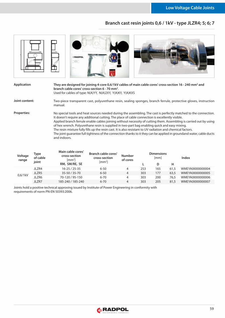
59
Low Voltage Cable Joints
Branch cast resin joints 0,6 / 1kV - type JLZR4; 5; 6; 7
They are designed for joining 4-core 0,6/1kV cables of main cable cores' cross-section 16 - 240 mm2 andbranch cable cores' cross-section 6 - 70 mm2.Used for cables of type: N(A)YY, N(A)2XY, Y(A)KY, Y(A)KXS
Two-piece transparent cast, polyurethane resin, sealing sponges, branch ferrule, protective gloves, instructionmanual.
No special tools and heat sources needed during the assembling. The cast is perfectly matched to the connection.It doesn't require any additional cutting. The place of cable connection is excellently visible.Applied branch ferrule enable cables joining without necessity of cutting them. Assembling is carried out by usingof hex wrench. Polyurethane resin is supplied in two-part bag enabling quick and easy mixing.The resin mixture fully fills up the resin cast. It is also resistant to UV radiation and chemical factors.The joint guarantee full tightness of the connection thanks to it they can be applied in groundand water, cable ductsand indoors.
Joints hold a positive technical approving issued by Institute of Power Engineering in conformity with requirements of norm PN-EN 50393:2006.
Voltagerange
Typeof cablejoint
Main cable cores'cross-section
[mm2]RM, SM/RE, SE
Branch cable cores'cross-section
[mm2]
Numberof cores
Dimensions[mm] Index
L D H
0,6/1kV
JLZR4 16-25 / 25-35 6-50 4 253 165 61,5 WMEYA0I000000004JLZR5 35-50 / 35-70 6-50 4 303 177 63,5 WMEYA0I000000005JLZR6 70-120 / 95-150 6-70 4 303 200 76,5 WMEYA0I000000006JLZR7 185-240 / 185-240 6-70 4 303 205 81,5 WMEYA0I000000007
Application
Joint content:
Properties:
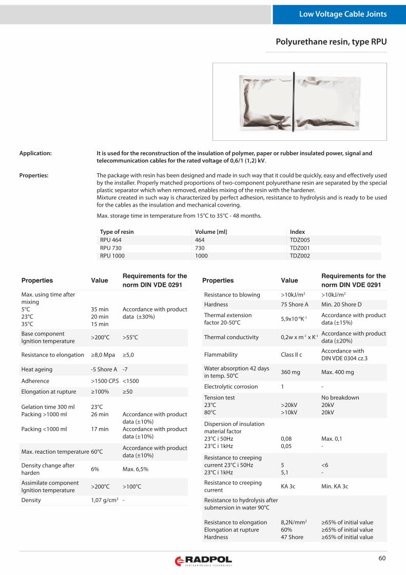
60
Low Voltage Cable Joints
Properties ValueRequirements for the
norm DIN VDE 0291
Max. using time aftermixing5°C 23°C 35°C
35 min20 min15 min
Accordance with productdata (±30%)
Base componentIgnition temperature >200°C >55°C
Resistance to elongation ≥8,0 Mpa ≥5,0
Heat ageing -5 Shore A -7
Adherence >1500 CP.S <1500
Elongation at rupture ≥100% ≥50
Gelation time 300 mlPacking >1000 ml
Packing <1000 ml
23°C 26 min
17 min
Accordance with productdata (±10%)Accordance with productdata (±10%)
Max. reaction temperature 60°C Accordance with productdata (±10%)
Density change afterharden 6% Max. 6,5%
Assimilate componentIgnition temperature >200°C >100°C
Density 1,07 g/cm3 -
Properties ValueRequirements for the
norm DIN VDE 0291
Resistance to blowing >10kJ/m2 >10kJ/m2
Hardness 75 Shore A Min. 20 Shore D
Thermal extensionfactor 20-50°C 5,9x10⁻⁴K-1 Accordance with product
data (±15%)
Thermal conductivity 0,2w x m-1 x K-1 Accordance with productdata (±20%)
Flammability Class II c Accordance withDIN VDE 0304 cz.3
Water absorption 42 daysin temp. 50°C 360 mg Max. 400 mg
Electrolytic corrosion 1 -
Tension test23°C 80°C
>20kV>10kV
No breakdown20kV20kV
Dispersion of insulationmaterial factor23°C i 50Hz23°C i 1kHz
0,080,05
Max. 0,1-
Resistance to creepingcurrent 23°C i 50Hz23°C i 1kHz
55,1
<6-
Resistance to creepingcurrent KA 3c Min. KA 3c
Resistance to hydrolysis aftersubmersion in water 90°C
Resistance to elongationElongation at ruptureHardness
8,2N/mm2
60%47 Shore
≥65% of initial value≥65% of initial value≥65% of initial value
Polyurethane resin, type RPU
It is used for the reconstruction of the insulation of polymer, paper or rubber insulated power, signal andtelecommunication cables for the rated voltage of 0,6/1 (1,2) kV.
The package with resin has been designed and made in such way that it could be quickly, easy and effectively usedby the installer. Properly matched proportions of two-component polyurethane resin are separated by the specialplastic separator which when removed, enables mixing of the resin with the hardener. Mixture created in such way is characterized by perfect adhesion, resistance to hydrolysis and is ready to be usedfor the cables as the insulation and mechanical covering.
Max. storage time in temperature from 15°C to 35°C - 48 months.
Application:
Properties:
Type of resin Volume [ml] IndexRPU 464 464 TDZ005RPU 730 730 TDZ001RPU 1000 1000 TDZ002

MEDIUM VOLTAGE CABLE JOINTS
Medium Voltage Joints
Straight cable joints for 3-core unscreened polymer insulated cables
Sets don't contain connectors. Joint sets are meant for joining cables with the use of compression connectors.Joint set can be used for cables with copper wire screen or with drain tapes.
designed for joining cables of type: NYY, NAYY, YKY, YAKY.
Heat shrink thick wall adhesive-layered tubes used for reconstruction of cores and connectors insulation.Additional insulation space is guaranteed by polyethylene spacer situated between the phase cores. Drain wire isreconstructed with the use of tinned copper sleeve installed by spring clips.Covering of the joint is formed by the heat shrink thick wall adhesive-layered tube.
• cover full range of cable cross-sections,• insulation layer of very high pressing strength,• high electrical and mechanical resistance due to heat shrink thick wall adhesive-layered tubes,• applied heat shrink tubes protect against moisture penetration.
Technical information:
Voltage range Cable cross-section [mm2] Type of cable joint Index
3,6/6kV i 6/6kV25-120 JHP-6-CX3 25-120 WMEJB0I030GL000195-240 JHP-6-CX3 95-240 WMEJB0I030KO0001
Properties of the joints:
61
3.6/6kV
Application:

Medium Voltage Joints
Straight cable joints for 3-core unscreened polymer insulated and armoured cables
Sets don't contain connectors. Joint sets are meant for joining cables with the use of crimping connectors.
heat shrink thick wall adhesive-layered tubes used for reconstruction of cores and connectors insulation.Additional insulation space is guaranteed by polyethylene spacer situated between the phase cores.Drain wire and metal armour are reconstructed with the use of tinned copper sleeve installed by spring clips.Covering of the joint is formed by the heat shrink thick wall adhesive-layered tube.
• cover full range of cable cross-sections,• insulation layer of very high pressing strength,• high electrical and mechanical resistance due to heat shrink thick wall adhesive-layered tubes,• applied heat shrink tubes protect against moisture penetration.
Technical information:
Voltage range Cable cross-section [mm2] Type of cable joint Index
3,6/6kV i 6/6kV25-120 JHP-6-CA3 25-120 WMEJB0A030GL000195-240 JHP-6-CA3 95-240 WMEJB0A030KO0001
Properties of the joints:
62
Application:for joining cables of type: N(A)YCY, N(A)YCWY, YAKYFty, YKYFty, YAKYFpy, YKYFpy, YAKYFoy, YKYFoy.
3.6/6kV

63
Cable straight joints for 1-core unscreened armoured polymerinsulated traction cables
The set is made as a single phase. Connectors not included.For connecting cables with the use of press connectors.
Voltage range Cable cross-section [mm2] Type of cable joint Index
3,6/6kV6/6kV 150-500 JHP-6-CA1 150-500 WMEJB0A030MS0001
Designed to connect cables: Y(A)KYFty, Y(A)KYFpy, Y(A)KYFoy.
Isolation of the joint and wire formed by a heat shrink thick-wall adhesive-layered tube. The return wireand metal armour are reconstructed with the use of tinned copper sleeve installed using spring clips withconstant contact pressure.
The joint is protected by a thick-wall adhesive-layered tube.• insulating layer with a high clamping pressure.• high electrical and mechanical strength thanks to the thick-wall adhesive-layered tubes used.• thick-wall adhesive-layered tube protects against moisture penetration.
Application:
Technical information:
Properties of the joint:
3.6/6kV
6/6kV
Medium Voltage Joints
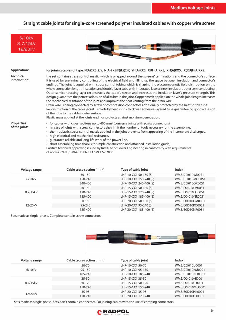
Medium Voltage Joints
Straight cable joints for single-core screened polymer insulated cables with copper wire screen
Sets made as single-phase. Complete contain screw connectors.
for joining cables of type: N(A)2XS(2)Y, N(A)2XS(F)(L)(2)Y, YH(A)KXS, XUH(A)KXS, XH(A)KXS , X(RU)H(A)KXS.
the set contains stress control mastic which is wrapped around the screens' terminations and the connector's surface.It is used for preliminary controlling of the electrical field and filling up the space between insulation and connector'sendings. The joint is supplied with stress control tubing which is shaping the electromagnetic field distribution on thewhole connection length, insulation and double-layer tube with integrated layers: inner insulation, outer semiconducting.Outer semiconducting layer reconstructs the cable's screen and increases the insulation layer's pressure strength. Thisdesign guarantees the perfect adhesion of all tubes in the joint. Copper mesh applied on the whole joint length increasesthe mechanical resistance of the joint and improves the heat venting from the drain wire.Drain wire is being connected by screw or compression connectors additionally protected by the heat shrink tube.Reconstruction of the cable jacket is made by heat shrink thick wall adhesive-layered tube guaranteeing good adhesionof the tube to the cable's outer surface.Plastic mass applied at the joints endings protects against moisture penetration.
• for cables with cross-sections up to 400 mm2 (concerns joints with screw connectors),• in case of joints with screw connectors they limit the number of tools necessary for the assembling,• thermoplastic stress control mastic applied in the joint prevents from appearing of the incomplete discharges,• high electrical and mechanical resistance,• guarantee reliable and long-life work of the power line,• short assembling time thanks to simple construction and attached installation guide,Positive technical approving issued by Institute of Power Engineering in conformity with requirementsof norms PN-90/E-06401 i PN-HD 629.1 S2:2006.
Application:
Technicalinformation:
Voltage range Cable cross-section [mm2] Type of cable joint Index
6/10kV50-150 JHP-10-CX1 50-150 (S) WMEJC0I010IM00S1
150-240 JHP-10-CX1 150-240 (S) WMEJC0I010MO00S1240-400 JHP-10-CX1 240-400 (S) WMEJC0I010OR00S1
8,7/15kV50-150 JHP-15-CX1 50-150 (S) WMEJD0I010IM00S1
120-240 JHP-15-CX1 120-240 (S) WMEJD0I010LO00S1185-400 JHP-15-CX1 185-400 (S) WMEJD0I010NR00S1
12/20kV50-150 JHP-20-CX1 50-150 (S) WMEJE0I010HM00S195-240 JHP-20-CX1 95-240 (S) WMEJE0I010KO00S1
185-400 JHP-20-CX1 185-400 (S) WMEJE0I010NR00S1
Propertiesof the joints:
64
Sets made as single-phase. Sets don't contain connectors. For joining cables with the use of crimping connectors.
Voltage range Cable cross-section [mm2] Type of cable joint Index
6/10kV50-70 JHP-10-CX1 50-70 WMEJC0I010IJ0001
95-150 JHP-10-CX1 95-150 WMEJC0I010KM0001185-240 JHP-10-CX1 185-240 WMEJC0I010NO0001
8,7/15kV35-50 JHP-15-CX1 35-50 WMEJD0I010HI0001
50-120 JHP-15-CX1 50-120 WMEJD0I010IL0001150-240 JHP-15-CX1 150-240 WMEJD0I010MO0001
12/20kV35-95 JHP-20-CX1 35-95 WMEJE0I010HK0001
120-240 JHP-20-CX1 120-240 WMEJE0I010LO0001
6/10kV
8,7/15kV
12/20kV
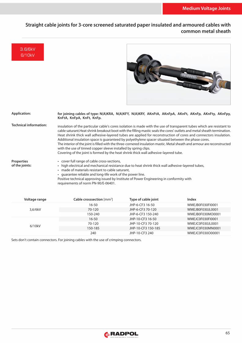
Medium Voltage Joints
Straight cable joints for 3-core screened saturated paper insulated and armoured cables withcommon metal sheath
Sets don't contain connectors. For joining cables with the use of crimping connectors.
for joining cables of type: N(A)KRA, N(A)KFY, N(A)KRY, AKnFtA, AKnFpA, AKnFt, AKnFp, AKnFty, AKnFpy,KnFtA, KnFpA, KnFt, KnFp.
insulation of the particular cable's cores isolation is made with the use of transparent tubes which are resistant tocable saturant.Heat shrink breakout boot with the filling mastic seals the cores' outlets and metal sheath termination.Heat shrink thick wall adhesive-layered tubes are applied for reconstruction of cores and connectors insulation.Additional insulation space is guaranteed by polyethylene spacer situated between the phase cores.The interior of the joint is filled with the three-cornered insulation mastic. Metal sheath and armour are reconstructedwith the use of tinned copper sleeve installed by spring clips. Covering of the joint is formed by the heat shrink thick wall adhesive-layered tube.
• cover full range of cable cross-sections,• high electrical and mechanical resistance due to heat shrink thick wall adhesive-layered tubes,• made of materials resistant to cable saturant,• guarantee reliable and long-life work of the power line.Positive technical approving issued by Institute of Power Engineering in conformity withrequirements of norm PN-90/E-06401.
Voltage range Cable crosssection [mm2] Type of cable joint Index
3,6/6kV16-50 JHP-6-CF3 16-50 WMEJB0F030FI0001
70-120 JHP-6-CF3 70-120 WMEJB0F030JL0001150-240 JHP-6-CF3 150-240 WMEJB0F030MO0001
6/10kV
16-50 JHP-10-CF3 16-50 WMEJC0F030FI000170-120 JHP-10-CF3 70-120 WMEJC0F030JL0001
150-185 JHP-10-CF3 150-185 WMEJC0F030MN0001240 JHP-10-CF3 240 WMEJC0F030O00001
Propertiesof the joints:
65
Technical information:
3.6/6kV
6/10kV
Application:
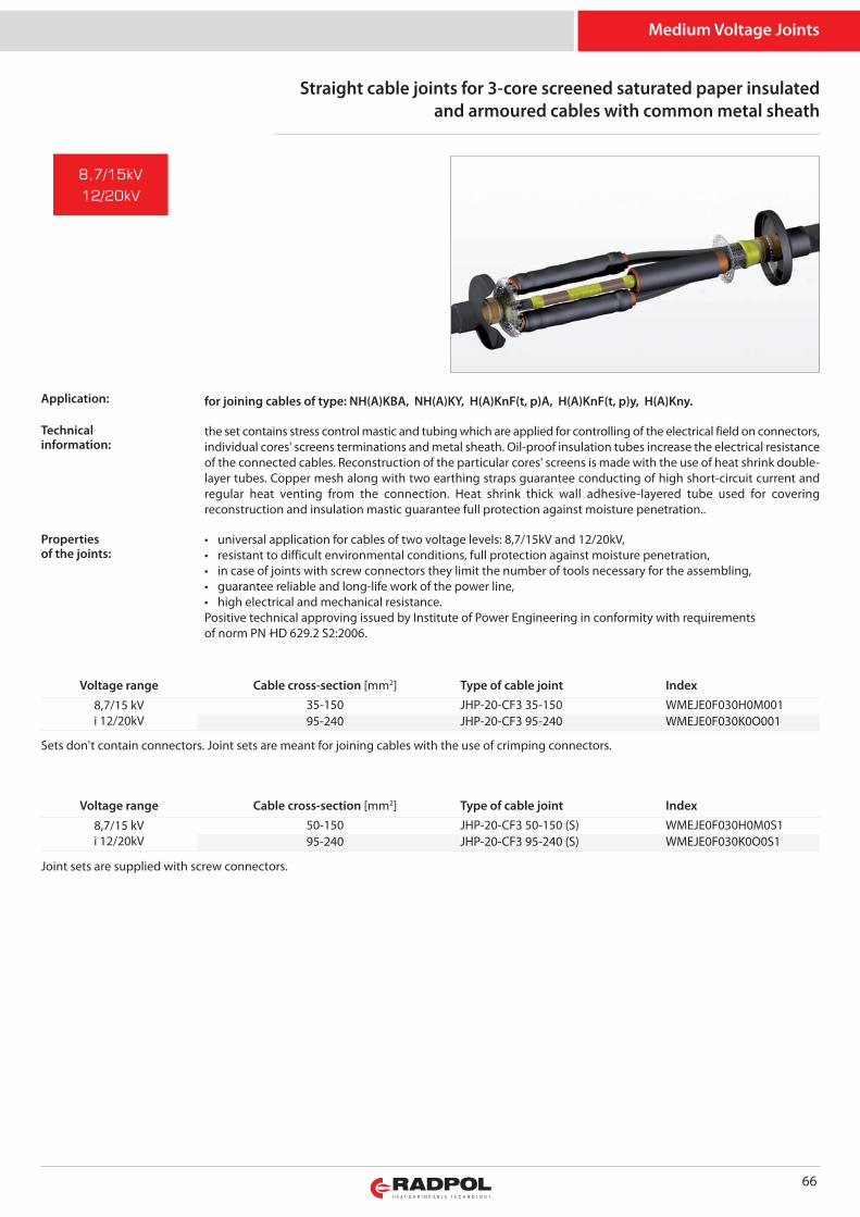
Medium Voltage Joints
66
Sets don't contain connectors. Joint sets are meant for joining cables with the use of crimping connectors.
for joining cables of type: NH(A)KBA, NH(A)KY, H(A)KnF(t, p)A, H(A)KnF(t, p)y, H(A)Kny.
the set contains stress control mastic and tubing which are applied for controlling of the electrical field on connectors,individual cores' screens terminations and metal sheath. Oil-proof insulation tubes increase the electrical resistanceof the connected cables. Reconstruction of the particular cores' screens is made with the use of heat shrink double-layer tubes. Copper mesh along with two earthing straps guarantee conducting of high short-circuit current andregular heat venting from the connection. Heat shrink thick wall adhesive-layered tube used for coveringreconstruction and insulation mastic guarantee full protection against moisture penetration..
• universal application for cables of two voltage levels: 8,7/15kV and 12/20kV,• resistant to difficult environmental conditions, full protection against moisture penetration,• in case of joints with screw connectors they limit the number of tools necessary for the assembling,• guarantee reliable and long-life work of the power line,• high electrical and mechanical resistance.Positive technical approving issued by Institute of Power Engineering in conformity with requirementsof norm PN -HD 629.2 S2:2006.
Voltage range Cable cross-section [mm2] Type of cable joint Index8,7/15 kVi 12/20kV
35-150 JHP-20-CF3 35-150 WMEJE0F030H0M00195-240 JHP-20-CF3 95-240 WMEJE0F030K0O001
Joint sets are supplied with screw connectors.
Voltage range Cable cross-section [mm2] Type of cable joint Index8,7/15 kVi 12/20kV
50-150 JHP-20-CF3 50-150 (S) WMEJE0F030H0M0S195-240 JHP-20-CF3 95-240 (S) WMEJE0F030K0O0S1
8,7/15kV
12/20kV
Straight cable joints for 3-core screened saturated paper insulatedand armoured cables with common metal sheath
Application:
Technicalinformation:
Propertiesof the joints:
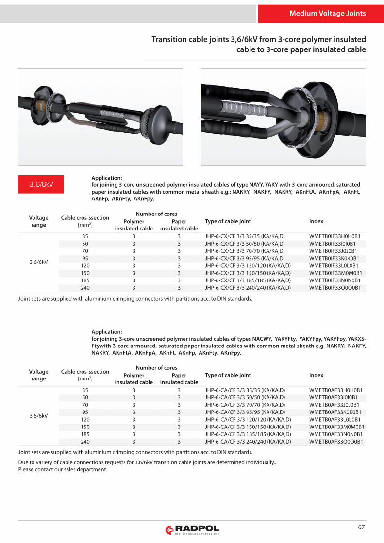
Medium Voltage Joints
67
Transition cable joints 3,6/6kV from 3-core polymer insulatedcable to 3-core paper insulated cable
Joint sets are supplied with aluminium crimping connectors with partitions acc. to DIN standards.
Application:for joining 3-core unscreened polymer insulated cables of type NAYY, YAKY with 3-core armoured, saturatedpaper insulated cables with common metal sheath e.g.: NAKRY, NAKFY, NAKRY, AKn FtA, AKn FpA, AKnFt,AKnFp, AKn Fty, AKn Fpy.
Application:for joining 3-core unscreened polymer insulated cables of types NACWY, YAKY Fty, YAKY Fpy, YAKY Foy, YAKXS -Ftywith 3-core armoured, saturated paper insulated cables with common metal sheath e.g. NAKRY, NAKFY,NAKRY, AKn FtA, AKn FpA, AKnFt, AKnFp, AKn Fty, AKn Fpy.
Voltagerange
Cable cros-ssection[mm2]
Number of coresType of cable joint IndexPolymer
insulated cablePaper
insulated cable
3,6/6kV
35 3 3 JHP-6-CX/CF 3/3 35/35 (KA/KA,D) WMETB0IF33H0H0B150 3 3 JHP-6-CX/CF 3/3 50/50 (KA/KA,D) WMETB0IF33I0I0B170 3 3 JHP-6-CX/CF 3/3 70/70 (KA/KA,D) WMETB0IF33J0J0B195 3 3 JHP-6-CX/CF 3/3 95/95 (KA/KA,D) WMETB0IF33K0K0B1
120 3 3 JHP-6-CX/CF 3/3 120/120 (KA/KA,D) WMETB0IF33L0L0B1150 3 3 JHP-6-CX/CF 3/3 150/150 (KA/KA,D) WMETB0IF33M0M0B1185 3 3 JHP-6-CX/CF 3/3 185/185 (KA/KA,D) WMETB0IF33N0N0B1240 3 3 JHP-6-CX/CF 3/3 240/240 (KA/KA,D) WMETB0IF33O0O0B1
Joint sets are supplied with aluminium crimping connectors with partitions acc. to DIN standards.
Due to variety of cable connections requests for 3,6/6kV transition cable joints are determined individually..Please contact our sales department.
Voltagerange
Cable cros-ssection[mm2]
Number of coresType of cable joint IndexPolymer
insulated cablePaper
insulated cable
3,6/6kV
35 3 3 JHP-6-CA/CF 3/3 35/35 (KA/KA,D) WMETB0AF33H0H0B150 3 3 JHP-6-CA/CF 3/3 50/50 (KA/KA,D) WMETB0AF33I0I0B170 3 3 JHP-6-CA/CF 3/3 70/70 (KA/KA,D) WMETB0AF33J0J0B195 3 3 JHP-6-CA/CF 3/3 95/95 (KA/KA,D) WMETB0AF33K0K0B1
120 3 3 JHP-6-CA/CF 3/3 120/120 (KA/KA,D) WMETB0AF33L0L0B1150 3 3 JHP-6-CA/CF 3/3 150/150 (KA/KA,D) WMETB0AF33M0M0B1185 3 3 JHP-6-CA/CF 3/3 185/185 (KA/KA,D) WMETB0AF33N0N0B1240 3 3 JHP-6-CA/CF 3/3 240/240 (KA/KA,D) WMETB0AF33O0O0B1
3,6/6kV
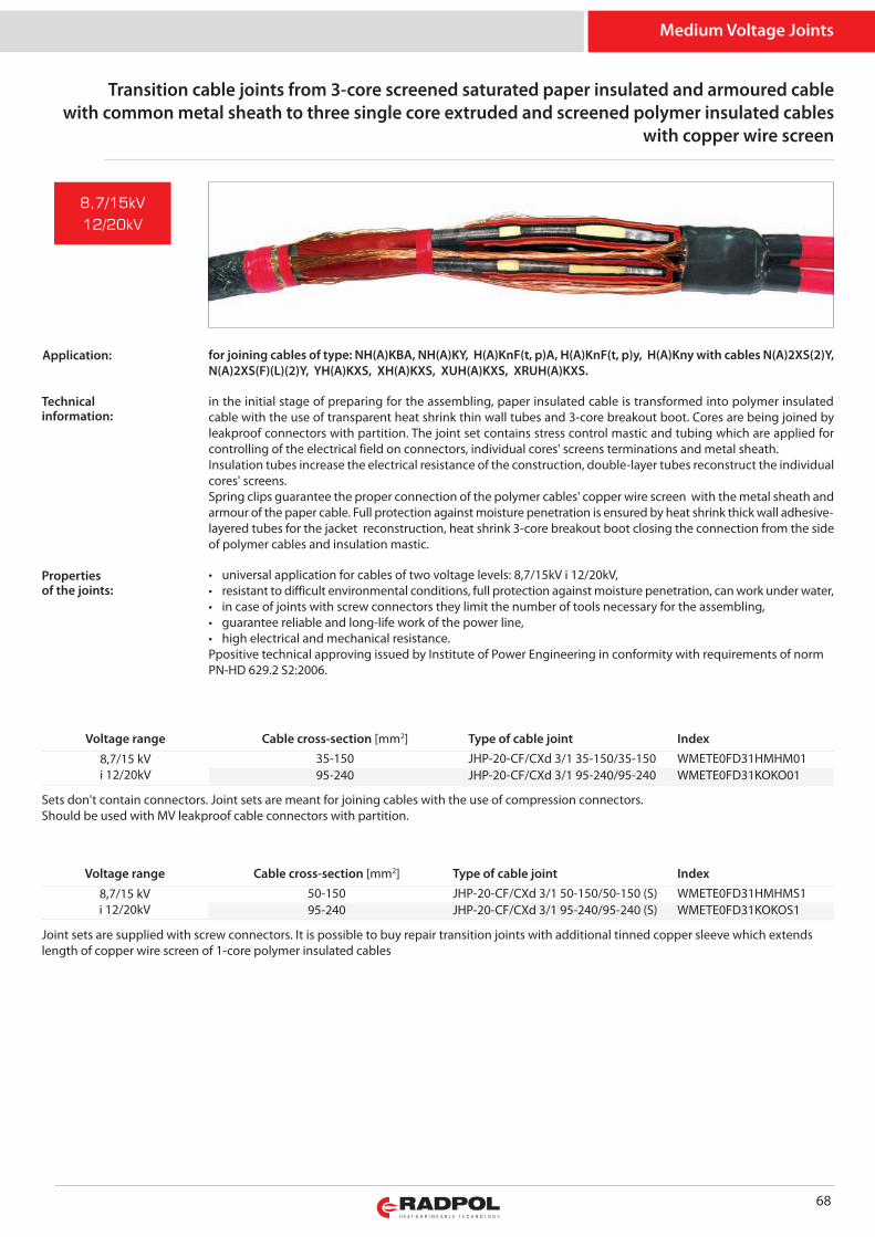
Medium Voltage Joints
68
Sets don't contain connectors. Joint sets are meant for joining cables with the use of compression connectors. Should be used with MV leakproof cable connectors with partition.
Voltage range Cable cross-section [mm2] Type of cable joint Index8,7/15 kVi 12/20kV
35-150 JHP-20-CF/CXd 3/1 35-150/35-150 WMETE0FD31HMHM0195-240 JHP-20-CF/CXd 3/1 95-240/95-240 WMETE0FD31KOKO01
for joining cables of type: NH(A)KBA, NH(A)KY, H(A)KnF(t, p)A, H(A)KnF(t, p)y, H(A)Kny with cables N(A)2XS(2)Y,N(A)2XS(F)(L)(2)Y, YH(A)KXS, XH(A)KXS, XUH(A)KXS, XRUH(A)KXS.
in the initial stage of preparing for the assembling, paper insulated cable is transformed into polymer insulatedcable with the use of transparent heat shrink thin wall tubes and 3-core breakout boot. Cores are being joined byleakproof connectors with partition. The joint set contains stress control mastic and tubing which are applied forcontrolling of the electrical field on connectors, individual cores' screens terminations and metal sheath.Insulation tubes increase the electrical resistance of the construction, double-layer tubes reconstruct the individualcores' screens. Spring clips guarantee the proper connection of the polymer cables' copper wire screen with the metal sheath andarmour of the paper cable. Full protection against moisture penetration is ensured by heat shrink thick wall adhesive-layered tubes for the jacket reconstruction, heat shrink 3-core breakout boot closing the connection from the sideof polymer cables and insulation mastic.
• universal application for cables of two voltage levels: 8,7/15kV i 12/20kV,• resistant to difficult environmental conditions, full protection against moisture penetration, can work under water,• in case of joints with screw connectors they limit the number of tools necessary for the assembling,• guarantee reliable and long-life work of the power line,• high electrical and mechanical resistance.Ppositive technical approving issued by Institute of Power Engineering in conformity with requirements of normPN-HD 629.2 S2:2006.
8,7/15kV
12/20kV
Joint sets are supplied with screw connectors. It is possible to buy repair transition joints with additional tinned copper sleeve which extendslength of copper wire screen of 1-core polymer insulated cables
Voltage range Cable cross-section [mm2] Type of cable joint Index8,7/15 kVi 12/20kV
50-150 JHP-20-CF/CXd 3/1 50-150/50-150 (S) WMETE0FD31HMHMS195-240 JHP-20-CF/CXd 3/1 95-240/95-240 (S) WMETE0FD31KOKOS1
Transition cable joints from 3-core screened saturated paper insulated and armoured cablewith common metal sheath to three single core extruded and screened polymer insulated cables
with copper wire screen
Application:
Technicalinformation:
Propertiesof the joints:
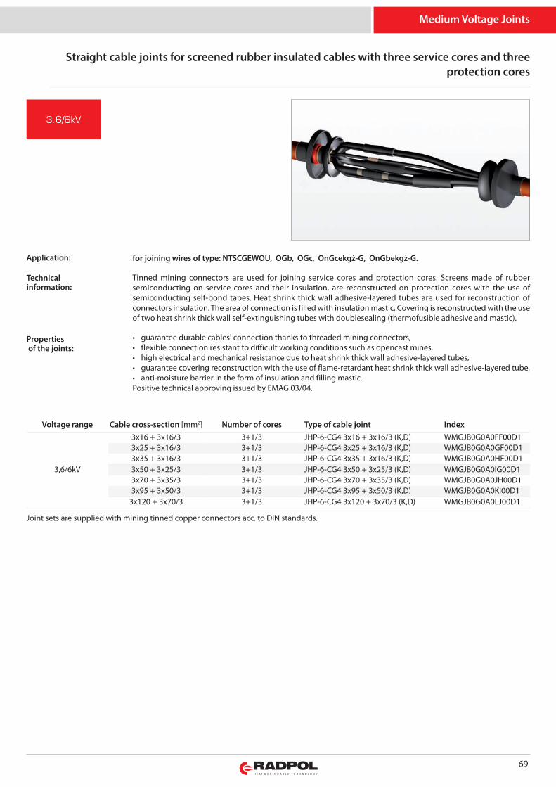
Medium Voltage Joints
Joint sets are supplied with mining tinned copper connectors acc. to DIN standards.
for joining wires of type: NTSCGEWOU, OGb, OGc, OnGcekgż-G, OnGbekgż-G.
Tinned mining connectors are used for joining service cores and protection cores. Screens made of rubbersemiconducting on service cores and their insulation, are reconstructed on protection cores with the use ofsemiconducting self-bond tapes. Heat shrink thick wall adhesive-layered tubes are used for reconstruction ofconnectors insulation. The area of connection is filled with insulation mastic. Covering is reconstructed with the useof two heat shrink thick wall self-extinguishing tubes with doublesealing (thermofusible adhesive and mastic).
• guarantee durable cables' connection thanks to threaded mining connectors,• flexible connection resistant to difficult working conditions such as opencast mines,• high electrical and mechanical resistance due to heat shrink thick wall adhesive-layered tubes,• guarantee covering reconstruction with the use of flame-retardant heat shrink thick wall adhesive-layered tube,• anti-moisture barrier in the form of insulation and filling mastic.Positive technical approving issued by EMAG 03/04.
Voltage range Cable cross-section [mm2] Number of cores Type of cable joint Index
3,6/6kV
3x16 + 3x16/3 3+1/3 JHP-6-CG4 3x16 + 3x16/3 (K,D) WMGJB0G0A0FF00D13x25 + 3x16/3 3+1/3 JHP-6-CG4 3x25 + 3x16/3 (K,D) WMGJB0G0A0GF00D13x35 + 3x16/3 3+1/3 JHP-6-CG4 3x35 + 3x16/3 (K,D) WMGJB0G0A0HF00D13x50 + 3x25/3 3+1/3 JHP-6-CG4 3x50 + 3x25/3 (K,D) WMGJB0G0A0IG00D13x70 + 3x35/3 3+1/3 JHP-6-CG4 3x70 + 3x35/3 (K,D) WMGJB0G0A0JH00D13x95 + 3x50/3 3+1/3 JHP-6-CG4 3x95 + 3x50/3 (K,D) WMGJB0G0A0KI00D1
3x120 + 3x70/3 3+1/3 JHP-6-CG4 3x120 + 3x70/3 (K,D) WMGJB0G0A0LJ00D1
69
3.6/6kV
Straight cable joints for screened rubber insulated cables with three service cores and threeprotection cores
Technicalinformation:
Propertiesof the joints:
Application:

Medium Voltage Joints
70
Straight cable joints for screened rubber insulated cables with three service coresand three protection cores
Joint sets are supplied with mining tinned copper connectors acc. to DIN standards.
tinned mining connectors are used for joining service cores and protection cores. Stress control mastic is wrappedaround the screens' terminations and the connector's surface. They are used for preliminary controlling of the electrical field and filling up the space between insulation andconnector's endings. The joint is supplied with stress control tubing which is shaping the electromagnetic field distribution on the wholeconnection length, insulation and double-layer tube with integrated layers: inner insulation and outersemiconducting. Heat shrink thick wall adhesive-layered flame-retardant tube is used for reconstruction of the outercovering. Protection against moisture penetration is guaranteed by applied both thermofusible adhesive and mastic.
• guarantee durable wires' connection thanks to threaded mining connectors,• cover cable cross-sections up to 185 mm2 of service core and up to 95 mm2 of protection core,• thermoplastic stress control mass applied in the joint set prevents from incomplete discharges occuring,• high electrical and mechanical durability, resistance to difficult working conditions such as opencast mines,• guarantee reliable and long-life work of the power line, • anti-moisture barrier in the form of insulation and filling masses.Positive technical approving issued by Institute of Power Engineering in conformity with requirements of normPN -HD 629.1 S2:2006.
Voltage range Cable cross-section [mm2] Number of cores Type of cable joint Index
6/10kV
3x16 + 3x16/3 3+1/3 JHP-10-CG4 3x16 + 3x16/3 (K,D) WMGJC0G0A0FF00D13x25 + 3x16/3 3+1/3 JHP-10-CG4 3x25 + 3x16/3 (K,D) WMGJC0G0A0GF00D13x35 + 3x16/3 3+1/3 JHP-10-CG4 3x35 + 3x16/3 (K,D) WMGJC0G0A0HF00D13x50 + 3x25/3 3+1/3 JHP-10-CG4 3x50 + 3x25/3 (K,D) WMGJC0G0A0IG00D13x70 + 3x35/3 3+1/3 JHP-10-CG4 3x70 + 3x35/3 (K,D) WMGJC0G0A0JH00D13x95 + 3x50/3 3+1/3 JHP-10-CG4 3x95 + 3x50/3 (K,D) WMGJC0G0A0KI00D1
3x120 + 3x70/3 3+1/3 JHP-10-CG4 3x120 + 3x70/3 (K,D) WMGJC0G0A0LJ00D13x150 + 3x70/3 3+1/3 JHP-10-CG4 3x150 + 3x70/3 (K,D) WMGJC0G0A0MJ00D13x185 + 3x95/3 3+1/3 JHP-10-CG4 3x185 + 3x95/3 (K,D) WMGJC0G0A0NK00D1
6/10kV Application:for joining mining wires of type: NTSCGEWOU, OnGcekgż-G (S), OnGcekgż-G (Z), OnGcrekgż-G (S),OnGcrekgż-G (Z) 6/10kV.
Technicalinformation:
Propertiesof the joints:
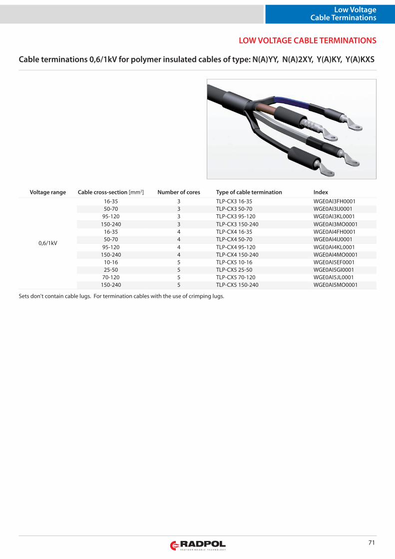
LOW VOLTAGE CABLE TERMINATIONS
Low VoltageCable Terminations
Cable terminations 0,6/1kV for polymer insulated cables of type: N(A)YY, N(A)2XY, Y(A)KY, Y(A)KXS
71
Voltage range Cable cross-section [mm2] Number of cores Type of cable termination Index
0,6/1kV
16-35 3 TLP-CX3 16-35 WGE0AI3FH000150-70 3 TLP-CX3 50-70 WGE0AI3IJ0001
95-120 3 TLP-CX3 95-120 WGE0AI3KL0001150-240 3 TLP-CX3 150-240 WGE0AI3MO0001
16-35 4 TLP-CX4 16-35 WGE0AI4FH000150-70 4 TLP-CX4 50-70 WGE0AI4IJ0001
95-120 4 TLP-CX4 95-120 WGE0AI4KL0001150-240 4 TLP-CX4 150-240 WGE0AI4MO0001
10-16 5 TLP-CX5 10-16 WGE0AI5EF000125-50 5 TLP-CX5 25-50 WGE0AI5GI0001
70-120 5 TLP-CX5 70-120 WGE0AI5JL0001150-240 5 TLP-CX5 150-240 WGE0AI5MO0001
Sets don't contain cable lugs. For termination cables with the use of crimping lugs.
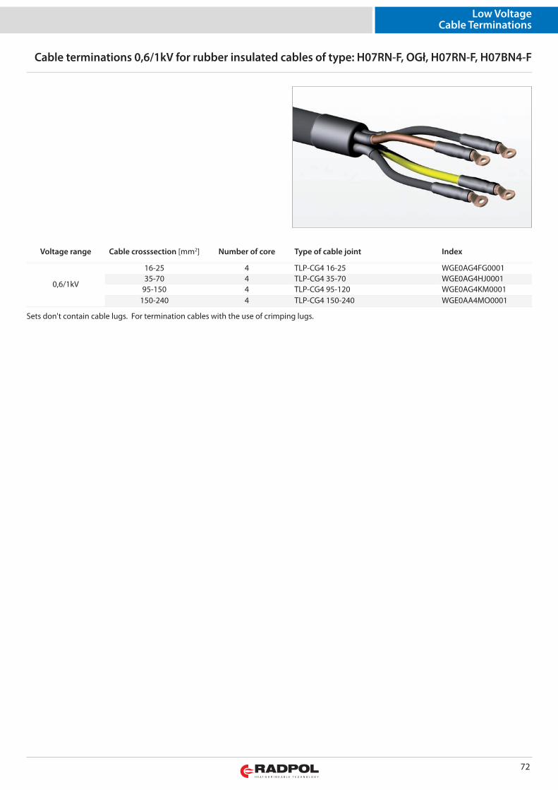
Low VoltageCable Terminations
72
Cable terminations 0,6/1kV for rubber insulated cables of type: H07RN-F, OGł, H07RN-F, H07BN4-F
Voltage range Cable crosssection [mm2] Number of core Type of cable joint Index
0,6/1kV
16-25 4 TLP-CG4 16-25 WGE0AG4FG000135-70 4 TLP-CG4 35-70 WGE0AG4HJ0001
95-150 4 TLP-CG4 95-120 WGE0AG4KM0001150-240 4 TLP-CG4 150-240 WGE0AA4MO0001
Sets don't contain cable lugs. For termination cables with the use of crimping lugs.
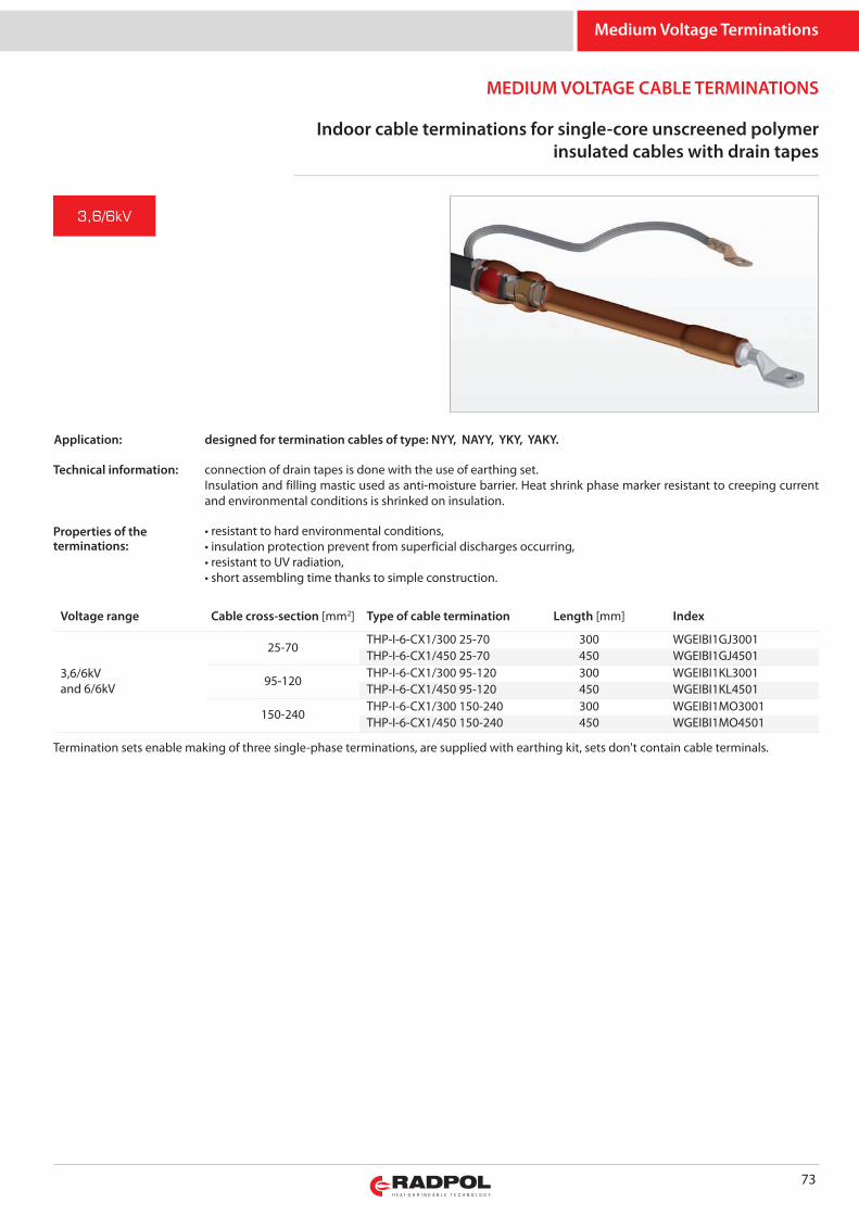
MEDIUM VOLTAGE CABLE TERMINATIONS
Medium Voltage Terminations
Indoor cable terminations for single-core unscreened polymerinsulated cables with drain tapes
73
designed for termination cables of type: NYY, NAYY, YKY, YAKY.
connection of drain tapes is done with the use of earthing set. Insulation and filling mastic used as anti-moisture barrier. Heat shrink phase marker resistant to creeping currentand environmental conditions is shrinked on insulation.
• resistant to hard environmental conditions,• insulation protection prevent from superficial discharges occurring,• resistant to UV radiation,• short assembling time thanks to simple construction.
3,6/6kV
Voltage range Cable cross-section [mm2] Type of cable termination Length [mm] Index
3,6/6kVand 6/6kV
25-70THP-I-6-CX1/300 25-70 300 WGEIBI1GJ3001THP-I-6-CX1/450 25-70 450 WGEIBI1GJ4501
95-120THP-I-6-CX1/300 95-120 300 WGEIBI1KL3001THP-I-6-CX1/450 95-120 450 WGEIBI1KL4501
150-240THP-I-6-CX1/300 150-240 300 WGEIBI1MO3001THP-I-6-CX1/450 150-240 450 WGEIBI1MO4501
Termination sets enable making of three single-phase terminations, are supplied with earthing kit, sets don't contain cable terminals.
Application:
Technical information:
Properties of theterminations:
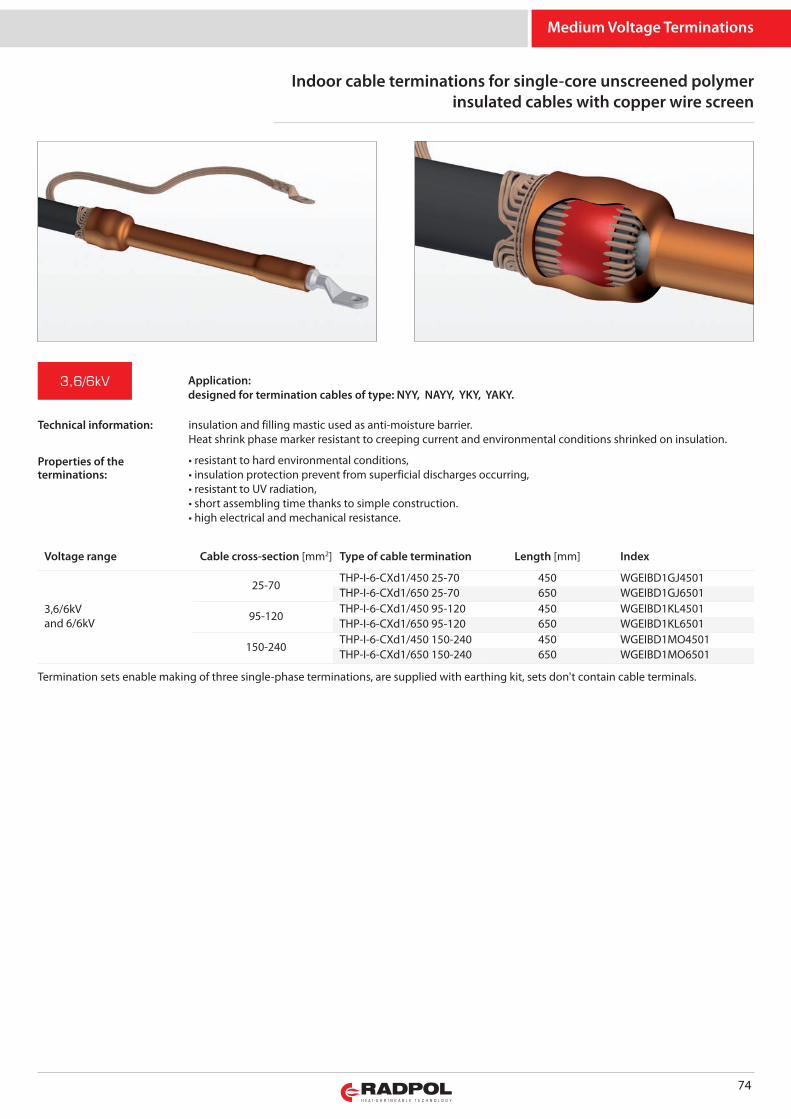
Medium Voltage Terminations
74
Indoor cable terminations for single-core unscreened polymerinsulated cables with copper wire screen
3,6/6kV
Voltage range Cable cross-section [mm2] Type of cable termination Length [mm] Index
3,6/6kVand 6/6kV
25-70THP-I-6-CXd1/450 25-70 450 WGEIBD1GJ4501THP-I-6-CXd1/650 25-70 650 WGEIBD1GJ6501
95-120THP-I-6-CXd1/450 95-120 450 WGEIBD1KL4501THP-I-6-CXd1/650 95-120 650 WGEIBD1KL6501
150-240THP-I-6-CXd1/450 150-240 450 WGEIBD1MO4501THP-I-6-CXd1/650 150-240 650 WGEIBD1MO6501
Termination sets enable making of three single-phase terminations, are supplied with earthing kit, sets don't contain cable terminals.
Application:designed for termination cables of type: NYY, NAYY, YKY, YAKY.
insulation and filling mastic used as anti-moisture barrier. Heat shrink phase marker resistant to creeping current and environmental conditions shrinked on insulation.
• resistant to hard environmental conditions,• insulation protection prevent from superficial discharges occurring,• resistant to UV radiation,• short assembling time thanks to simple construction.• high electrical and mechanical resistance.
Technical information:
Properties of theterminations:
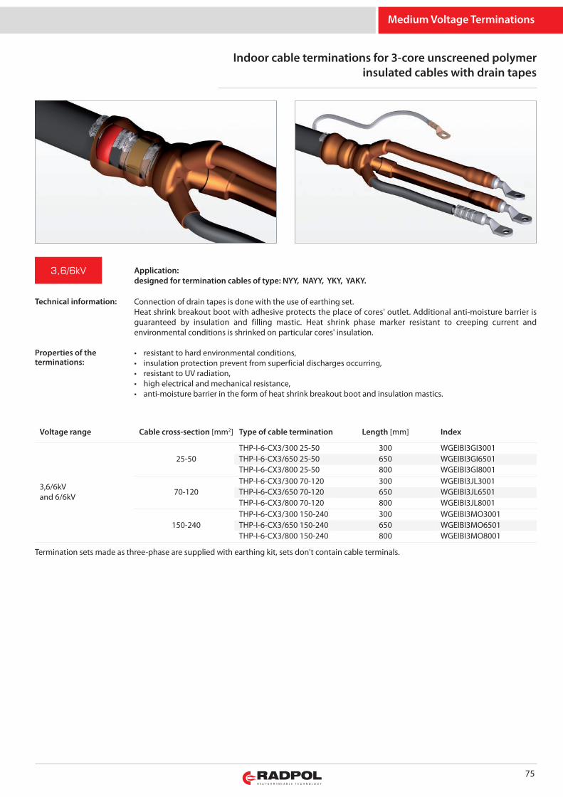
Medium Voltage Terminations
Indoor cable terminations for 3-core unscreened polymerinsulated cables with drain tapes
75
Application:designed for termination cables of type: NYY, NAYY, YKY, YAKY.
3,6/6kV
Voltage range Cable cross-section [mm2] Type of cable termination Length [mm] Index
3,6/6kVand 6/6kV
25-50THP-I-6-CX3/300 25-50 300 WGEIBI3GI3001THP-I-6-CX3/650 25-50 650 WGEIBI3GI6501THP-I-6-CX3/800 25-50 800 WGEIBI3GI8001
70-120THP-I-6-CX3/300 70-120 300 WGEIBI3JL3001THP-I-6-CX3/650 70-120 650 WGEIBI3JL6501THP-I-6-CX3/800 70-120 800 WGEIBI3JL8001
150-240THP-I-6-CX3/300 150-240 300 WGEIBI3MO3001THP-I-6-CX3/650 150-240 650 WGEIBI3MO6501THP-I-6-CX3/800 150-240 800 WGEIBI3MO8001
Termination sets made as three-phase are supplied with earthing kit, sets don't contain cable terminals.
Connection of drain tapes is done with the use of earthing set.Heat shrink breakout boot with adhesive protects the place of cores' outlet. Additional anti-moisture barrier isguaranteed by insulation and filling mastic. Heat shrink phase marker resistant to creeping current andenvironmental conditions is shrinked on particular cores' insulation.
• resistant to hard environmental conditions,• insulation protection prevent from superficial discharges occurring,• resistant to UV radiation,• high electrical and mechanical resistance,• anti-moisture barrier in the form of heat shrink breakout boot and insulation mastics.
Technical information:
Properties of theterminations:
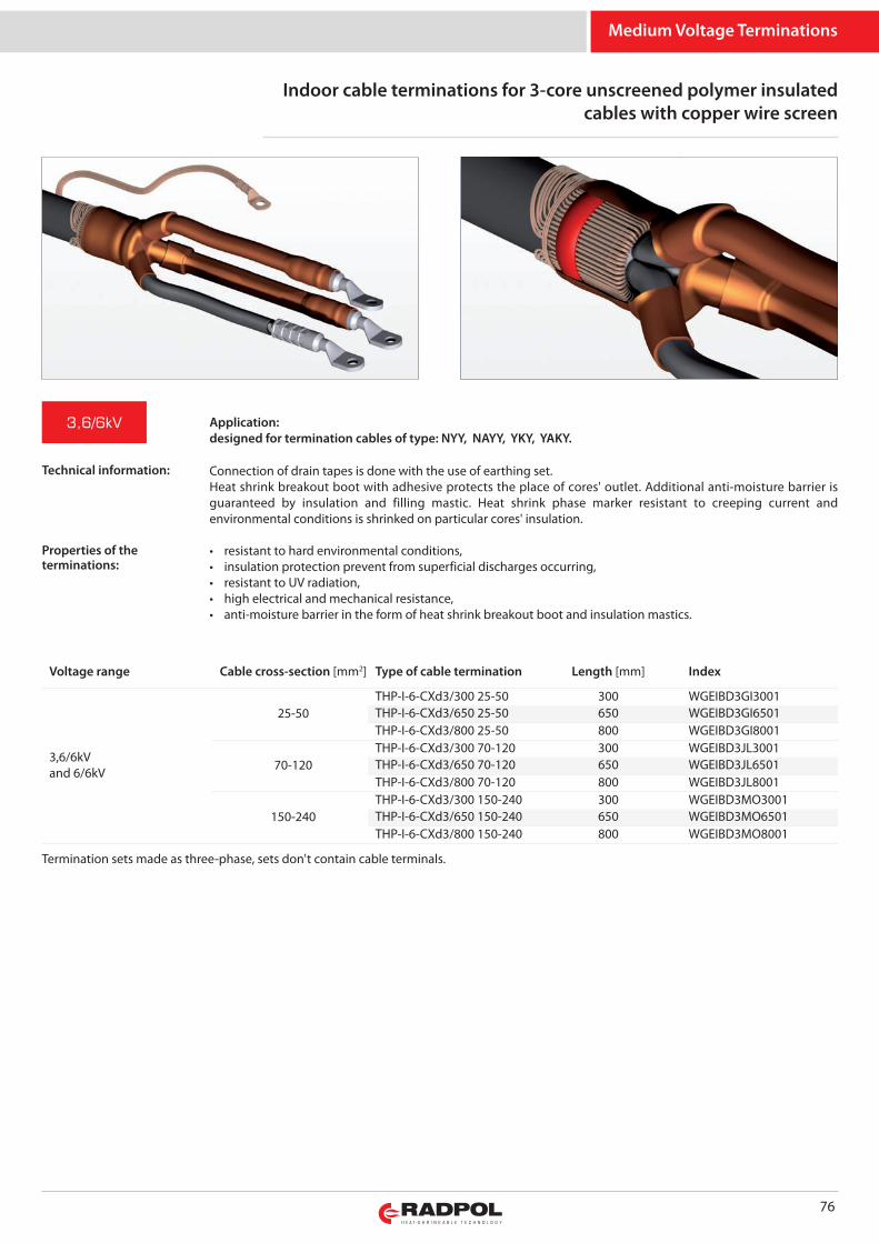
Medium Voltage Terminations
76
Voltage range Cable cross-section [mm2] Type of cable termination Length [mm] Index
3,6/6kVand 6/6kV
25-50THP-I-6-CXd3/300 25-50 300 WGEIBD3GI3001THP-I-6-CXd3/650 25-50 650 WGEIBD3GI6501THP-I-6-CXd3/800 25-50 800 WGEIBD3GI8001
70-120THP-I-6-CXd3/300 70-120 300 WGEIBD3JL3001THP-I-6-CXd3/650 70-120 650 WGEIBD3JL6501THP-I-6-CXd3/800 70-120 800 WGEIBD3JL8001
150-240THP-I-6-CXd3/300 150-240 300 WGEIBD3MO3001THP-I-6-CXd3/650 150-240 650 WGEIBD3MO6501THP-I-6-CXd3/800 150-240 800 WGEIBD3MO8001
Connection of drain tapes is done with the use of earthing set.Heat shrink breakout boot with adhesive protects the place of cores' outlet. Additional anti-moisture barrier isguaranteed by insulation and filling mastic. Heat shrink phase marker resistant to creeping current andenvironmental conditions is shrinked on particular cores' insulation.
• resistant to hard environmental conditions,• insulation protection prevent from superficial discharges occurring,• resistant to UV radiation,• high electrical and mechanical resistance,• anti-moisture barrier in the form of heat shrink breakout boot and insulation mastics.
Termination sets made as three-phase, sets don't contain cable terminals.
Application:designed for termination cables of type: NYY, NAYY, YKY, YAKY.
3,6/6kV
Indoor cable terminations for 3-core unscreened polymer insulatedcables with copper wire screen
Technical information:
Properties of theterminations:
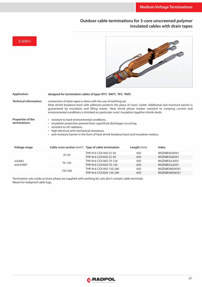
Medium Voltage Terminations
Outdoor cable terminations for 3-core unscreened polymerinsulated cables with drain tapes
77
designed for termination cables of type: NYY, NAYY, YKY, YAKY.
connection of drain tapes is done with the use of earthing set.Heat shrink breakout boot with adhesive protects the place of cores' outlet. Additional anti-moisture barrier isguaranteed by insulation and filling mastic. Heat shrink phase marker resistant to creeping current andenvironmental conditions is shrinked on particular cores' insulation together shrink sheds.
• resistant to hard environmental conditions,• insulation protection prevent from superficial discharges occurring,• resistant to UV radiation,• high electrical and mechanical resistance,• anti-moisture barrier in the form of heat shrink breakout boot and insulation mastics.
3,6/6kV
Voltage range Cable cross-section [mm2] Type of cable termination Length [mm] Index
3,6/6kVand 6/6kV
25-50THP-N-6-CX3/450 25-50 450 WGENBI3GI4501THP-N-6-CX3/650 25-50 650 WGENBI3GI6501
70-120THP-N-6-CX3/450 70-120 450 WGENBI3JL4501THP-N-6-CX3/650 70-120 650 WGENBI3JL6501
150-240THP-N-6-CX3/450 150-240 450 WGENBI3MO4501THP-N-6-CX3/650 150-240 650 WGENBI3MO6501
Termination sets made as three-phase are supplied with earthing kit, sets don't contain cable terminals.Meant for leakproof cable lugs.
Application:
Technical information:
Properties of theterminations:
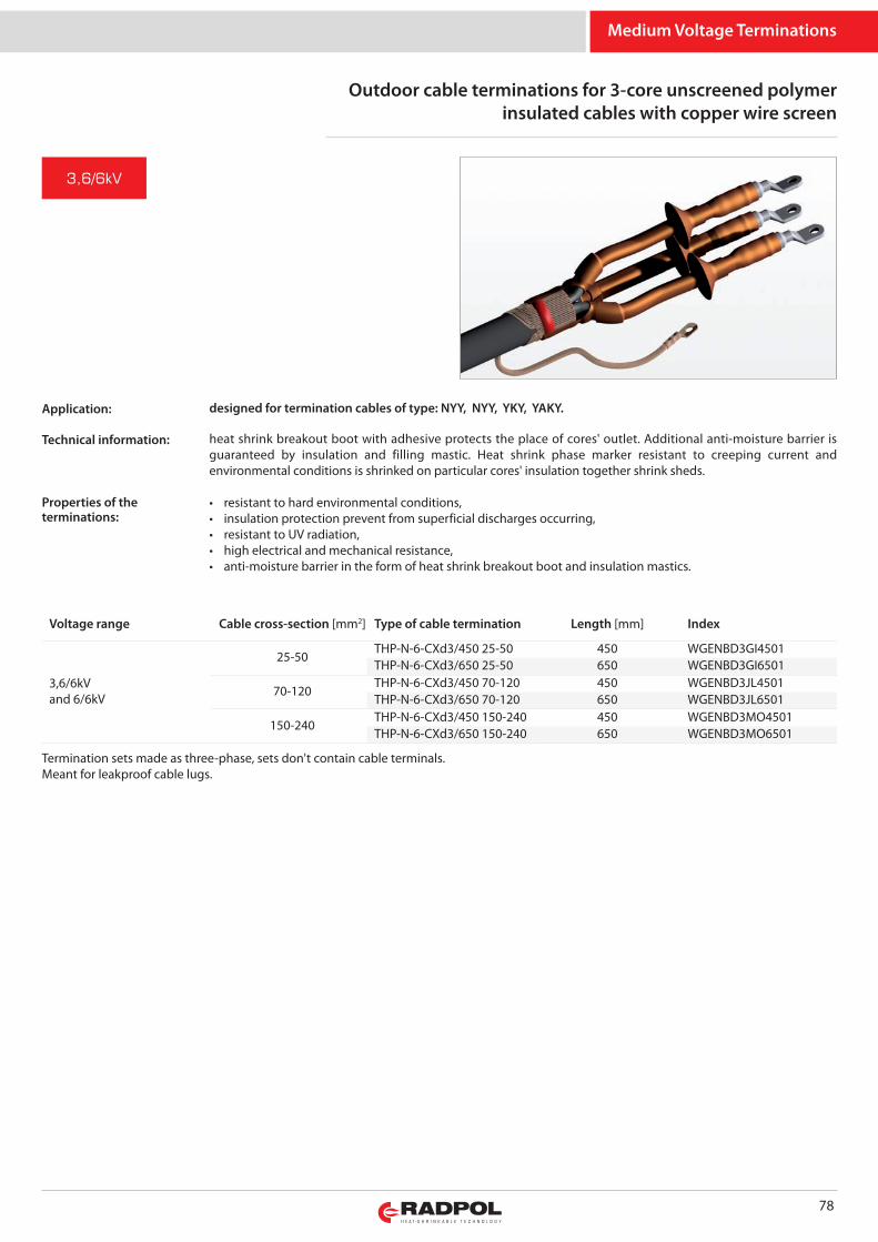
Medium Voltage Terminations
78
Voltage range Cable cross-section [mm2] Type of cable termination Length [mm] Index
3,6/6kVand 6/6kV
25-50THP-N-6-CXd3/450 25-50 450 WGENBD3GI4501THP-N-6-CXd3/650 25-50 650 WGENBD3GI6501
70-120THP-N-6-CXd3/450 70-120 450 WGENBD3JL4501THP-N-6-CXd3/650 70-120 650 WGENBD3JL6501
150-240THP-N-6-CXd3/450 150-240 450 WGENBD3MO4501THP-N-6-CXd3/650 150-240 650 WGENBD3MO6501
Outdoor cable terminations for 3-core unscreened polymerinsulated cables with copper wire screen
3,6/6kV
designed for termination cables of type: NYY, NYY, YKY, YAKY.
heat shrink breakout boot with adhesive protects the place of cores' outlet. Additional anti-moisture barrier isguaranteed by insulation and filling mastic. Heat shrink phase marker resistant to creeping current andenvironmental conditions is shrinked on particular cores' insulation together shrink sheds.
• resistant to hard environmental conditions,• insulation protection prevent from superficial discharges occurring,• resistant to UV radiation,• high electrical and mechanical resistance,• anti-moisture barrier in the form of heat shrink breakout boot and insulation mastics.
Termination sets made as three-phase, sets don't contain cable terminals.Meant for leakproof cable lugs.
Application:
Technical information:
Properties of theterminations:
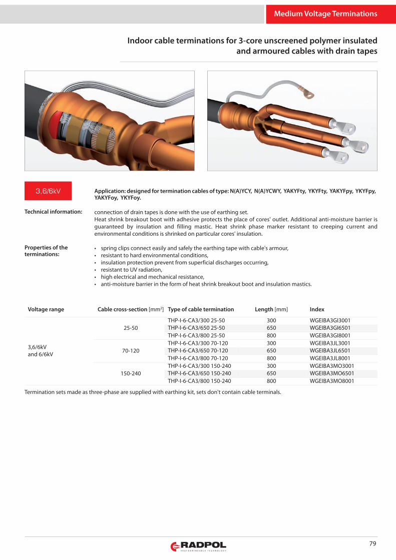
Medium Voltage Terminations
Indoor cable terminations for 3-core unscreened polymer insulatedand armoured cables with drain tapes
79
connection of drain tapes is done with the use of earthing set.Heat shrink breakout boot with adhesive protects the place of cores' outlet. Additional anti-moisture barrier isguaranteed by insulation and filling mastic. Heat shrink phase marker resistant to creeping current andenvironmental conditions is shrinked on particular cores' insulation.
• spring clips connect easily and safely the earthing tape with cable's armour,• resistant to hard environmental conditions,• insulation protection prevent from superficial discharges occurring,• resistant to UV radiation,• high electrical and mechanical resistance,• anti-moisture barrier in the form of heat shrink breakout boot and insulation mastics.
3,6/6kV
Voltage range Cable cross-section [mm2] Type of cable termination Length [mm] Index
3,6/6kVand 6/6kV
25-50THP-I-6-CA3/300 25-50 300 WGEIBA3GI3001THP-I-6-CA3/650 25-50 650 WGEIBA3GI6501THP-I-6-CA3/800 25-50 800 WGEIBA3GI8001
70-120THP-I-6-CA3/300 70-120 300 WGEIBA3JL3001THP-I-6-CA3/650 70-120 650 WGEIBA3JL6501THP-I-6-CA3/800 70-120 800 WGEIBA3JL8001
150-240THP-I-6-CA3/300 150-240 300 WGEIBA3MO3001THP-I-6-CA3/650 150-240 650 WGEIBA3MO6501THP-I-6-CA3/800 150-240 800 WGEIBA3MO8001
Termination sets made as three-phase are supplied with earthing kit, sets don't contain cable terminals.
Application: designed for termination cables of type: N(A)YCY, N(A)YCWY, YAKYFty, YKYFty, YAKYFpy, YKYFpy,YAKYFoy, YKYFoy.
Technical information:
Properties of theterminations:
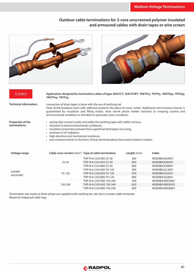
Medium Voltage Terminations
80
Outdoor cable terminations for 3-core unscreened polymer insulatedand armoured cables with drain tapes or wire screen
3,6/6kV
Voltage range Cable cross-section [mm2] Type of cable termination Length [mm] Index
3,6/6kVand 6/6kV
25-50THP-N-6-CA3/300 25-50 300 WGENBA3GI3001THP-N-6-CA3/650 25-50 650 WGENBA3GI6501THP-N-6-CA3/800 25-50 800 WGENBA3GI8001
70-120THP-N-6-CA3/300 70-120 300 WGENBA3JL3001THP-N-6-CA3/650 70-120 650 WGENBA3JL6501THP-N-6-CA3/800 70-120 800 WGENBA3JL8001
150-240THP-N-6-CA3/300 150-240 300 WGENBA3MO3001THP-N-6-CA3/650 150-240 650 WGENBA3MO6501THP-N-6-CA3/800 150-240 800 WGENBA3MO8001
connection of drain tapes is done with the use of earthing set.Heat shrink breakout boot with adhesive protects the place of cores' outlet. Additional anti-moisture barrier isguaranteed by insulation and filling mastic. Heat shrink phase marker resistant to creeping current andenvironmental conditions is shrinked on particular cores' insulation.
• spring clips connect easily and safely the earthing tape with cable's armour,• resistant to hard environmental conditions,• insulation protection prevent from superficial discharges occurring,• resistant to UV radiation,• high electrical and mechanical resistance,• anti-moisture barrier in the form of heat shrink breakout boot and insulation mastics.
Termination sets made as three-phase are supplied with earthing kit, sets don't contain cable terminals.Meant for leakproof cable lugs.
Application: designed for termination cables of type: N(A)YCY, N(A)YCWY, YAKYFty, YKYFty, YAKYFpy, YKYFpy,YAKYFoy, YKYFoy.
Technical information:
Properties of theterminations:
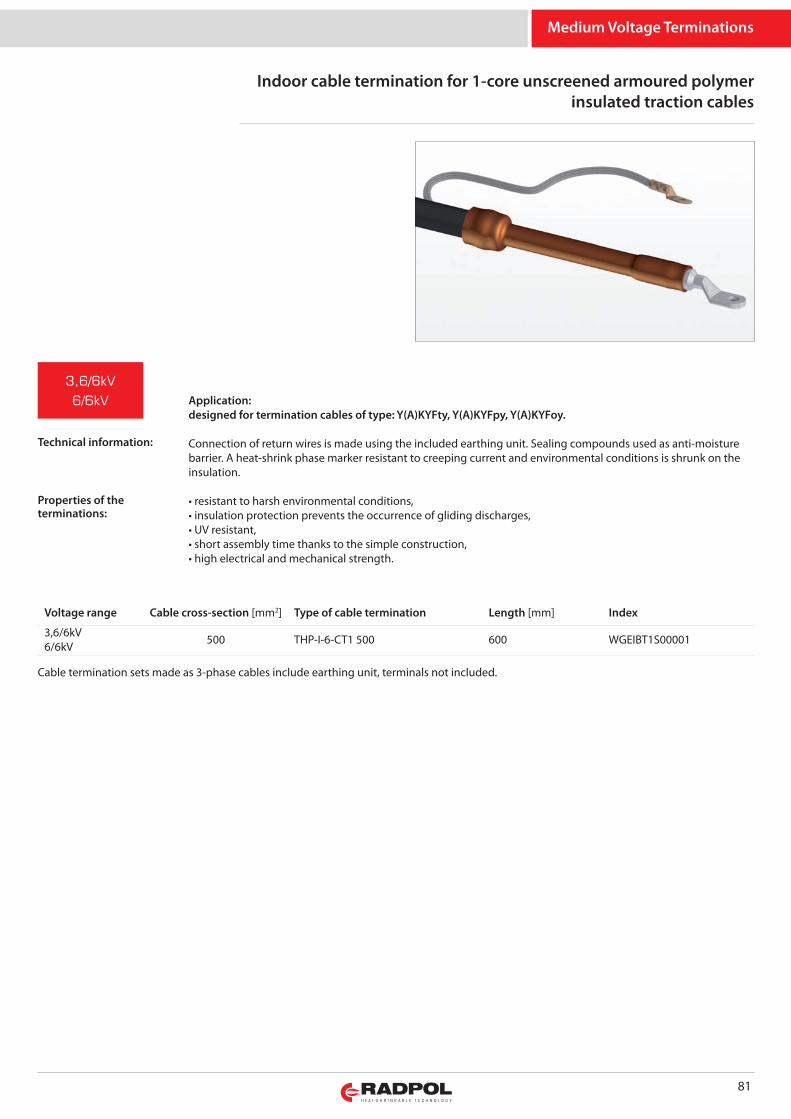
Medium Voltage Terminations
Indoor cable termination for 1-core unscreened armoured polymerinsulated traction cables
81
Application:designed for termination cables of type: Y(A)KYFty, Y(A)KYFpy, Y(A)KYFoy.
Connection of return wires is made using the included earthing unit. Sealing compounds used as anti-moisturebarrier. A heat-shrink phase marker resistant to creeping current and environmental conditions is shrunk on theinsulation.
• resistant to harsh environmental conditions,• insulation protection prevents the occurrence of gliding discharges,• UV resistant,• short assembly time thanks to the simple construction,• high electrical and mechanical strength.
Cable termination sets made as 3-phase cables include earthing unit, terminals not included.
3,6/6kV
6/6kV
Voltage range Cable cross-section [mm2] Type of cable termination Length [mm] Index
3,6/6kV6/6kV 500 THP-I-6-CT1 500 600 WGEIBT1S00001
Technical information:
Properties of theterminations:

Medium Voltage Terminations
Outdoor cable termination for 1-core unscreened armoured polymerinsulated traction cables
82
Application:designed for termination cables of type: Y(A)KYFty, Y(A)KYFpy, Y(A)KYFoy.
Connection of return wires is made using the included earthing unit.Sealing compounds used as anti-moisture barrier. A heat-shrink phase marker with cable entry seal are shrunk onthe insulation. Resistant to creeping current and environmental conditions.
• resistant to harsh environmental conditions,• insulation protection prevents the occurrence of gliding discharges,• UV resistant,• short assembly time thanks to the simple construction,• high electrical and mechanical strength.
One 1-phase cable termination can be made using the set, terminals are not included.
3,6/6kV
6/6kV
Voltage range Cable cross-section [mm2] Type of cable termination Length [mm] Index
3,6/6kV6/6kV 500 THP-N-6-CT1 500 600 WGENBT1S00001
Technical information:
Properties of theterminations:
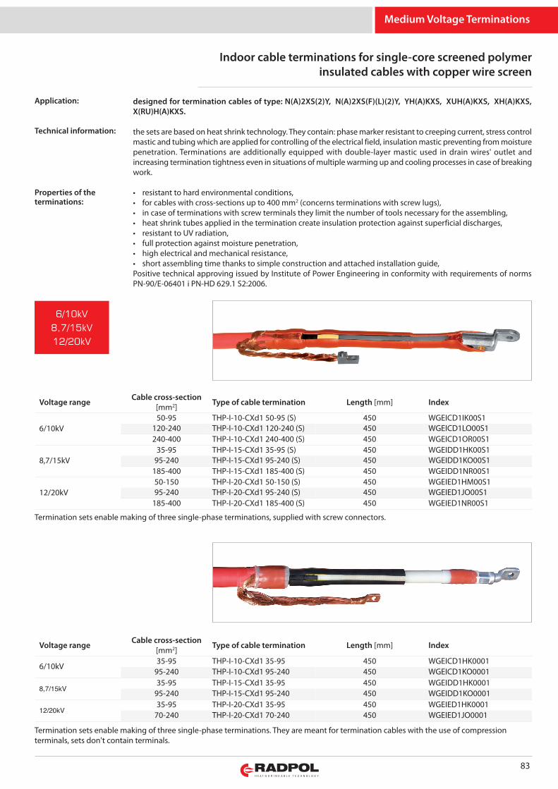
designed for termination cables of type: N(A)2XS(2)Y, N(A)2XS(F)(L)(2)Y, YH(A)KXS, XUH(A)KXS, XH(A)KXS,X(RU)H(A)KXS.
the sets are based on heat shrink technology. They contain: phase marker resistant to creeping current, stress controlmastic and tubing which are applied for controlling of the electrical field, insulation mastic preventing from moisturepenetration. Terminations are additionally equipped with double-layer mastic used in drain wires' outlet andincreasing termination tightness even in situations of multiple warming up and cooling processes in case of breakingwork.
• resistant to hard environmental conditions,• for cables with cross-sections up to 400 mm2 (concerns terminations with screw lugs), • in case of terminations with screw terminals they limit the number of tools necessary for the assembling,• heat shrink tubes applied in the termination create insulation protection against superficial discharges,• resistant to UV radiation,• full protection against moisture penetration,• high electrical and mechanical resistance,• short assembling time thanks to simple construction and attached installation guide,Positive technical approving issued by Institute of Power Engineering in conformity with requirements of normsPN-90/E-06401 i PN-HD 629.1 S2:2006.
Medium Voltage Terminations
Indoor cable terminations for single-core screened polymerinsulated cables with copper wire screen
83
Voltage range Cable cross-section[mm2] Type of cable termination Length [mm] Index
6/10kV50-95 THP-I-10-CXd1 50-95 (S) 450 WGEICD1IK00S1
120-240 THP-I-10-CXd1 120-240 (S) 450 WGEICD1LO00S1240-400 THP-I-10-CXd1 240-400 (S) 450 WGEICD1OR00S1
8,7/15kV35-95 THP-I-15-CXd1 35-95 (S) 450 WGEIDD1HK00S1
95-240 THP-I-15-CXd1 95-240 (S) 450 WGEIDD1KO00S1185-400 THP-I-15-CXd1 185-400 (S) 450 WGEIDD1NR00S1
12/20kV50-150 THP-I-20-CXd1 50-150 (S) 450 WGEIED1HM00S195-240 THP-I-20-CXd1 95-240 (S) 450 WGEIED1JO00S1
185-400 THP-I-20-CXd1 185-400 (S) 450 WGEIED1NR00S1
Termination sets enable making of three single-phase terminations, supplied with screw connectors.
6/10kV
8,7/15kV
12/20kV
Voltage range Cable cross-section[mm2] Type of cable termination Length [mm] Index
6/10kV35-95 THP-I-10-CXd1 35-95 450 WGEICD1HK0001
95-240 THP-I-10-CXd1 95-240 450 WGEICD1KO0001
8,7/15kV35-95 THP-I-15-CXd1 35-95 450 WGEIDD1HK0001
95-240 THP-I-15-CXd1 95-240 450 WGEIDD1KO0001
12/20kV35-95 THP-I-20-CXd1 35-95 450 WGEIED1HK0001
70-240 THP-I-20-CXd1 70-240 450 WGEIED1JO0001
Termination sets enable making of three single-phase terminations. They are meant for termination cables with the use of compressionterminals, sets don't contain terminals.
Application:
Technical information:
Properties of theterminations:
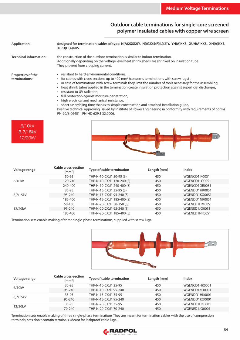
Medium Voltage Terminations
Outdoor cable terminations for single-core screenedpolymer insulated cables with copper wire screen
84
Voltage range Cable cross-section[mm2] Type of cable termination Length [mm] Index
6/10kV50-95 THP-N-10-CXd1 50-95 (S) 450 WGENCD1IK00S1
120-240 THP-N-10-CXd1 120-240 (S) 450 WGENCD1LO00S1240-400 THP-N-10-CXd1 240-400 (S) 450 WGENCD1OR00S1
8,7/15kV35-95 THP-N-15-CXd1 35-95 (S) 450 WGENDD1HK00S1
95-240 THP-N-15-CXd1 95-240 (S) 450 WGENDD1KO00S1185-400 THP-N-15-CXd1 185-400 (S) 450 WGENDD1NR00S1
12/20kV50-150 THP-N-20-CXd1 50-150 (S) 450 WGENED1HM00S195-240 THP-N-20-CXd1 95-240 (S) 450 WGENED1JO00S1
185-400 THP-N-20-CXd1 185-400 (S) 450 WGENED1NR00S1
Termination sets enable making of three single-phase terminations, supplied with screw lugs.
6/10kV
8,7/15kV
12/20kV
Voltage range Cable cross-section[mm2] Type of cable termination Length [mm] Index
6/10kV35-95 THP-N-10-CXd1 35-95 450 WGENCD1HK0001
95-240 THP-N-10-CXd1 95-240 450 WGENCD1KO0001
8,7/15kV35-95 THP-N-15-CXd1 35-95 450 WGENDD1HK0001
95-240 THP-N-15-CXd1 95-240 450 WGENDD1KO0001
12/20kV35-95 THP-N-20-CXd1 35-95 450 WGENED1HK0001
70-240 THP-N-20-CXd1 70-240 450 WGENED1JO0001
Termination sets enable making of three single-phase terminations They are meant for termination cables with the use of compressionterminals, sets don't contain terminals. Meant for leakproof cable lugs.
designed for termination cables of type: N(A)2XS(2)Y, N(A)2XS(F)(L)(2)Y, YH(A)KXS, XUH(A)KXS, XH(A)KXS,X(RU)H(A)KXS.
the construction of the outdoor termination is similar to indoor termination.Additionally depending on the voltage level heat shrink sheds are shrinked on insulation tube.They prevent from creeping current.
• resistant to hard environmental conditions,• for cables with cross-sections up to 400 mm2 (concerns terminations with screw lugs) ,• in case of terminations with screw terminals they limit the number of tools necessary for the assembling,• heat shrink tubes applied in the termination create insulation protection against superficial discharges,• resistant to UV radiation,• full protection against moisture penetration,• high electrical and mechanical resistance,• short assembling time thanks to simple construction and attached installation guide,Positive technical approving issued by Institute of Power Engineering in conformity with requirements of normsPN-90/E-06401 i PN-HD 629.1 S2:2006.
Application:
Technical information:
Properties of theterminations:
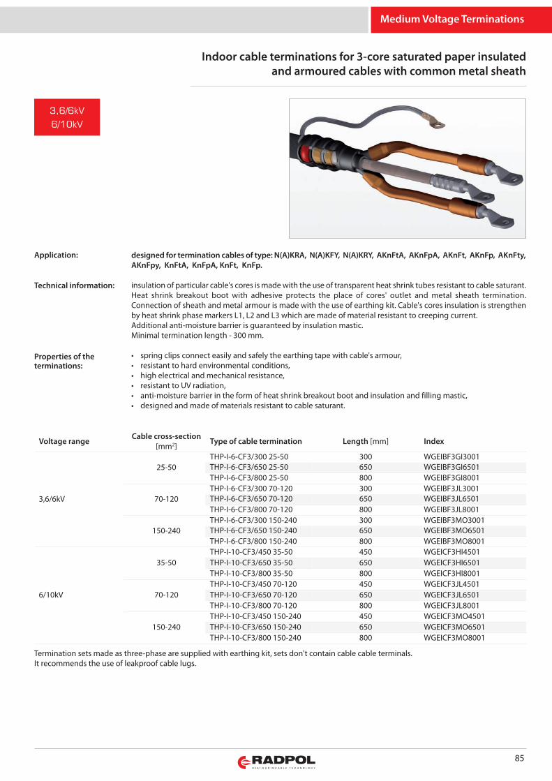
Medium Voltage Terminations
Indoor cable terminations for 3-core saturated paper insulatedand armoured cables with common metal sheath
85
Termination sets made as three-phase are supplied with earthing kit, sets don't contain cable cable terminals.It recommends the use of leakproof cable lugs.
3,6/6kV
6/10kV
Voltage range Cable cross-section[mm2] Type of cable termination Length [mm] Index
3,6/6kV
25-50THP-I-6-CF3/300 25-50 300 WGEIBF3GI3001THP-I-6-CF3/650 25-50 650 WGEIBF3GI6501THP-I-6-CF3/800 25-50 800 WGEIBF3GI8001
70-120THP-I-6-CF3/300 70-120 300 WGEIBF3JL3001THP-I-6-CF3/650 70-120 650 WGEIBF3JL6501THP-I-6-CF3/800 70-120 800 WGEIBF3JL8001
150-240THP-I-6-CF3/300 150-240 300 WGEIBF3MO3001THP-I-6-CF3/650 150-240 650 WGEIBF3MO6501THP-I-6-CF3/800 150-240 800 WGEIBF3MO8001
6/10kV
35-50THP-I-10-CF3/450 35-50 450 WGEICF3HI4501THP-I-10-CF3/650 35-50 650 WGEICF3HI6501THP-I-10-CF3/800 35-50 800 WGEICF3HI8001
70-120THP-I-10-CF3/450 70-120 450 WGEICF3JL4501THP-I-10-CF3/650 70-120 650 WGEICF3JL6501THP-I-10-CF3/800 70-120 800 WGEICF3JL8001
150-240THP-I-10-CF3/450 150-240 450 WGEICF3MO4501THP-I-10-CF3/650 150-240 650 WGEICF3MO6501THP-I-10-CF3/800 150-240 800 WGEICF3MO8001
designed for termination cables of type: N(A)KRA, N(A)KFY, N(A)KRY, AKnFtA, AKnFpA, AKnFt, AKnFp, AKnFty,AKnFpy, KnFtA, KnFpA, KnFt, KnFp.
insulation of particular cable's cores is made with the use of transparent heat shrink tubes resistant to cable saturant.Heat shrink breakout boot with adhesive protects the place of cores' outlet and metal sheath termination.Connection of sheath and metal armour is made with the use of earthing kit. Cable's cores insulation is strengthenby heat shrink phase markers L1, L2 and L3 which are made of material resistant to creeping current. Additional anti-moisture barrier is guaranteed by insulation mastic.Minimal termination length - 300 mm.
• spring clips connect easily and safely the earthing tape with cable's armour,• resistant to hard environmental conditions,• high electrical and mechanical resistance,• resistant to UV radiation,• anti-moisture barrier in the form of heat shrink breakout boot and insulation and filling mastic,• designed and made of materials resistant to cable saturant.
Application:
Technical information:
Properties of theterminations:
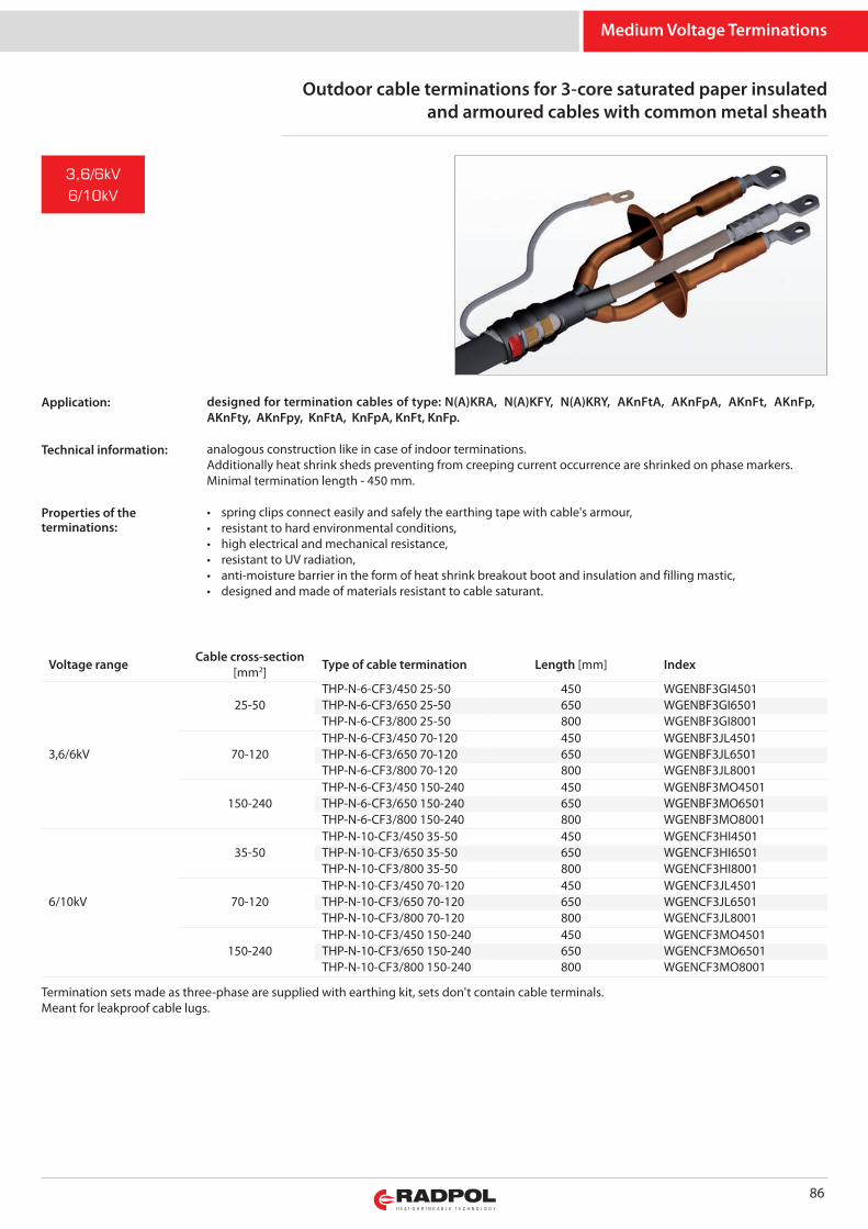
Medium Voltage Terminations
Outdoor cable terminations for 3-core saturated paper insulatedand armoured cables with common metal sheath
86
designed for termination cables of type: N(A)KRA, N(A)KFY, N(A)KRY, AKnFtA, AKnFpA, AKnFt, AKnFp,AKnFty, AKnFpy, KnFtA, KnFpA, KnFt, KnFp.
analogous construction like in case of indoor terminations.Additionally heat shrink sheds preventing from creeping current occurrence are shrinked on phase markers.Minimal termination length - 450 mm.
• spring clips connect easily and safely the earthing tape with cable's armour,• resistant to hard environmental conditions,• high electrical and mechanical resistance,• resistant to UV radiation,• anti-moisture barrier in the form of heat shrink breakout boot and insulation and filling mastic,• designed and made of materials resistant to cable saturant.
Termination sets made as three-phase are supplied with earthing kit, sets don't contain cable terminals.Meant for leakproof cable lugs.
3,6/6kV
6/10kV
Voltage range Cable cross-section[mm2] Type of cable termination Length [mm] Index
3,6/6kV
25-50THP-N-6-CF3/450 25-50 450 WGENBF3GI4501THP-N-6-CF3/650 25-50 650 WGENBF3GI6501THP-N-6-CF3/800 25-50 800 WGENBF3GI8001
70-120THP-N-6-CF3/450 70-120 450 WGENBF3JL4501THP-N-6-CF3/650 70-120 650 WGENBF3JL6501THP-N-6-CF3/800 70-120 800 WGENBF3JL8001
150-240THP-N-6-CF3/450 150-240 450 WGENBF3MO4501THP-N-6-CF3/650 150-240 650 WGENBF3MO6501THP-N-6-CF3/800 150-240 800 WGENBF3MO8001
6/10kV
35-50THP-N-10-CF3/450 35-50 450 WGENCF3HI4501THP-N-10-CF3/650 35-50 650 WGENCF3HI6501THP-N-10-CF3/800 35-50 800 WGENCF3HI8001
70-120THP-N-10-CF3/450 70-120 450 WGENCF3JL4501THP-N-10-CF3/650 70-120 650 WGENCF3JL6501THP-N-10-CF3/800 70-120 800 WGENCF3JL8001
150-240THP-N-10-CF3/450 150-240 450 WGENCF3MO4501THP-N-10-CF3/650 150-240 650 WGENCF3MO6501THP-N-10-CF3/800 150-240 800 WGENCF3MO8001
Application:
Technical information:
Properties of theterminations:
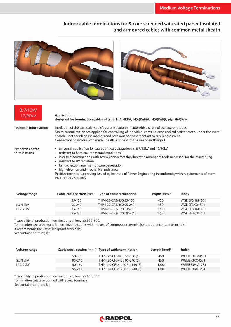
Medium Voltage Terminations
Indoor cable terminations for 3-core screened saturated paper insulatedand armoured cables with common metal sheath
87
insulation of the particular cable's cores isolation is made with the use of transparent tubes. Stress control mastic are applied for controlling of individual cores' screens and collective screen under the metalsheath. Heat shrink phase markers and breakout boot are resistant to creeping current.Connection of armour with metal sheath is done with the use of earthing kit.
• universal application for cables of two voltage levels: 8,7/15kV and 12/20kV,• resistant to hard environmental conditions,• in case of terminations with screw connectors they limit the number of tools necessary for the assembling,• resistant to UV radiation,• full protection against moisture penetration,• high electrical and mechanical resistance.Positive technical approving issued by Institute of Power Engineering in conformity with requirements of normPN-HD 629.2 S2:2006.
* capability of production terminations of lenghts 650, 800.Termination sets are meant for terminating cables with the use of compression terminals (sets don't contain terminals).It recommends the use of leakproof terminals.Set contains earthing kit.
8,7/15kV
12/20kV
Voltage range Cable cross-section [mm2] Type of cable termination Length [mm]* Index
8,7/15kVi 12/20kV
35-150 THP-I-20-CF3/450 35-150 450 WGEIEF3HM450195-240 THP-I-20-CF3/450 95-240 450 WGEIEF3KO450135-150 THP-I-20-CF3/1200 35-150 1200 WGEIEF3HM120195-240 THP-I-20-CF3/1200 95-240 1200 WGEIEF3KO1201
* capability of production terminations of lenghts 650, 800.Termination sets are supplied with screw terminals.Set contains earthing kit.
Voltage range Cable cross-section [mm2] Type of cable termination Length [mm]* Index
8,7/15kVi 12/20kV
50-150 THP-I-20-CF3/450 50-150 (S) 450 WGEIEF3HM45S195-240 THP-I-20-CF3/450 95-240 (S) 450 WGEIEF3KO45S150-150 THP-I-20-CF3/1200 50-150 (S) 1200 WGEIEF3HM12S195-240 THP-I-20-CF3/1200 95-240 (S) 1200 WGEIEF3KO12S1
Application:designed for termination cables of type: N(A)HKBA, H(A)KnFtA, H(A)KnF(t, p)y, H(A)Kny.
Technical information:
Properties of theterminations:
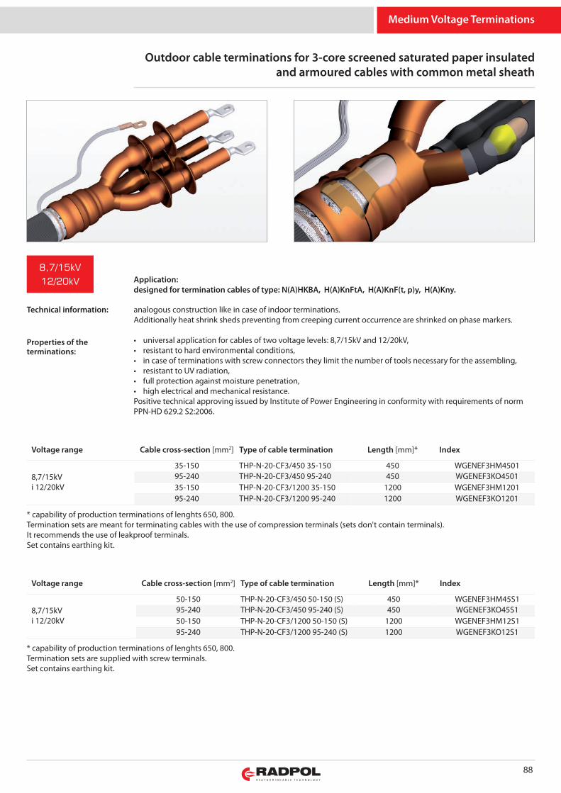
Medium Voltage Terminations
Outdoor cable terminations for 3-core screened saturated paper insulatedand armoured cables with common metal sheath
88
analogous construction like in case of indoor terminations.Additionally heat shrink sheds preventing from creeping current occurrence are shrinked on phase markers.
• universal application for cables of two voltage levels: 8,7/15kV and 12/20kV,• resistant to hard environmental conditions,• in case of terminations with screw connectors they limit the number of tools necessary for the assembling,• resistant to UV radiation,• full protection against moisture penetration,• high electrical and mechanical resistance.Positive technical approving issued by Institute of Power Engineering in conformity with requirements of normPPN-HD 629.2 S2:2006.
* capability of production terminations of lenghts 650, 800.Termination sets are meant for terminating cables with the use of compression terminals (sets don't contain terminals).It recommends the use of leakproof terminals.Set contains earthing kit.
Voltage range Cable cross-section [mm2] Type of cable termination Length [mm]* Index
8,7/15kVi 12/20kV
35-150 THP-N-20-CF3/450 35-150 450 WGENEF3HM450195-240 THP-N-20-CF3/450 95-240 450 WGENEF3KO450135-150 THP-N-20-CF3/1200 35-150 1200 WGENEF3HM120195-240 THP-N-20-CF3/1200 95-240 1200 WGENEF3KO1201
* capability of production terminations of lenghts 650, 800.Termination sets are supplied with screw terminals.Set contains earthing kit.
Voltage range Cable cross-section [mm2] Type of cable termination Length [mm]* Index
8,7/15kVi 12/20kV
50-150 THP-N-20-CF3/450 50-150 (S) 450 WGENEF3HM45S195-240 THP-N-20-CF3/450 95-240 (S) 450 WGENEF3KO45S150-150 THP-N-20-CF3/1200 50-150 (S) 1200 WGENEF3HM12S195-240 THP-N-20-CF3/1200 95-240 (S) 1200 WGENEF3KO12S1
8,7/15kV
12/20kV Application:designed for termination cables of type: N(A)HKBA, H(A)KnFtA, H(A)KnF(t, p)y, H(A)Kny.
Technical information:
Properties of theterminations:
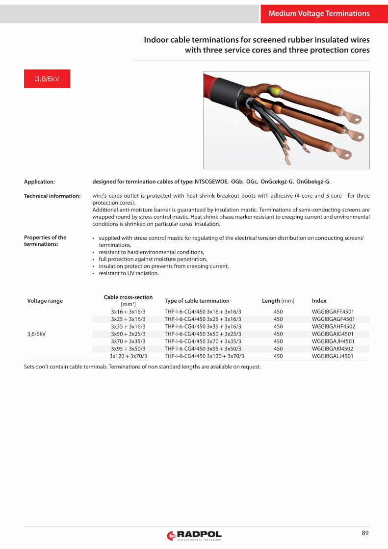
Medium Voltage Terminations
Indoor cable terminations for screened rubber insulated wireswith three service cores and three protection cores
89
designed for termination cables of type: NTSCGEWOE, OGb, OGc, OnGcekgż-G, OnGbekgż-G.
wire's cores outlet is protected with heat shrink breakout boots with adhesive (4-core and 3-core - for threeprotection cores).Additional anti-moisture barrier is guaranteed by insulation mastic. Terminations of semi-conducting screens arewrapped round by stress control mastic. Heat shrink phase marker resistant to creeping current and environmentalconditions is shrinked on particular cores' insulation.
• supplied with stress control mastic for regulating of the electrical tension distribution on conducting screens' terminations,
• resistant to hard environmental conditions,• full protection against moisture penetration,• insulation protection prevents from creeping current,• resistant to UV radiation.
Sets don't contain cable terminals. Terminations of non standard lengths are available on request.
Voltage range Cable cross-section[mm2] Type of cable termination Length [mm] Index
3,6/6kV
3x16 + 3x16/3 THP-I-6-CG4/450 3x16 + 3x16/3 450 WGGIBGAFF45013x25 + 3x16/3 THP-I-6-CG4/450 3x25 + 3x16/3 450 WGGIBGAGF45013x35 + 3x16/3 THP-I-6-CG4/450 3x35 + 3x16/3 450 WGGIBGAHF45023x50 + 3x25/3 THP-I-6-CG4/450 3x50 + 3x25/3 450 WGGIBGAIG45013x70 + 3x35/3 THP-I-6-CG4/450 3x70 + 3x35/3 450 WGGIBGAJH45013x95 + 3x50/3 THP-I-6-CG4/450 3x95 + 3x50/3 450 WGGIBGAKI4502
3x120 + 3x70/3 THP-I-6-CG4/450 3x120 + 3x70/3 450 WGGIBGALJ4501
3,6/6kV
Application:
Technical information:
Properties of theterminations:
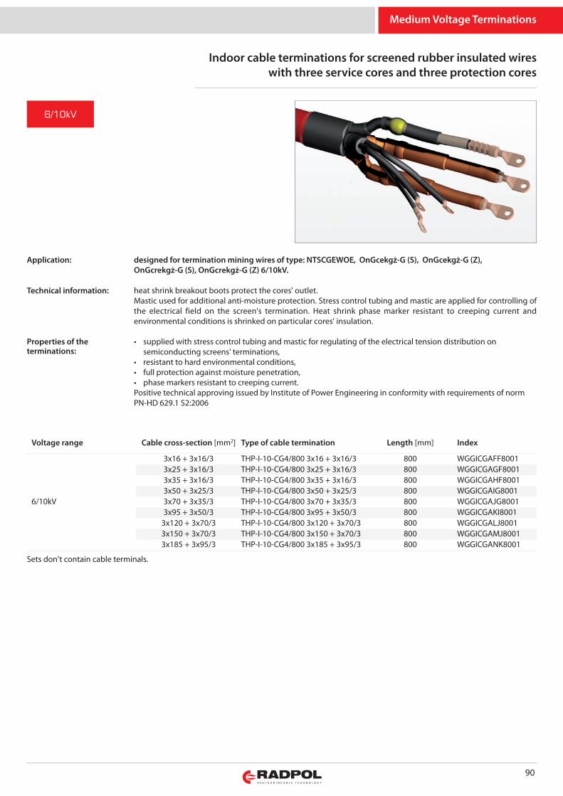
Medium Voltage Terminations
90
Indoor cable terminations for screened rubber insulated wireswith three service cores and three protection cores
designed for termination mining wires of type: NTSCGEWOE, OnGcekgż-G (S), OnGcekgż-G (Z),OnGcrekgż-G (S), OnGcrekgż-G (Z) 6/10kV.
heat shrink breakout boots protect the cores' outlet. Mastic used for additional anti-moisture protection. Stress control tubing and mastic are applied for controlling ofthe electrical field on the screen's termination. Heat shrink phase marker resistant to creeping current andenvironmental conditions is shrinked on particular cores' insulation.
• supplied with stress control tubing and mastic for regulating of the electrical tension distribution on semiconducting screens' terminations,
• resistant to hard environmental conditions,• full protection against moisture penetration,• phase markers resistant to creeping current.Positive technical approving issued by Institute of Power Engineering in conformity with requirements of normPN-HD 629.1 S2:2006
Sets don't contain cable terminals.
Voltage range Cable cross-section [mm2] Type of cable termination Length [mm] Index
6/10kV
3x16 + 3x16/3 THP-I-10-CG4/800 3x16 + 3x16/3 800 WGGICGAFF80013x25 + 3x16/3 THP-I-10-CG4/800 3x25 + 3x16/3 800 WGGICGAGF80013x35 + 3x16/3 THP-I-10-CG4/800 3x35 + 3x16/3 800 WGGICGAHF80013x50 + 3x25/3 THP-I-10-CG4/800 3x50 + 3x25/3 800 WGGICGAIG80013x70 + 3x35/3 THP-I-10-CG4/800 3x70 + 3x35/3 800 WGGICGAJG80013x95 + 3x50/3 THP-I-10-CG4/800 3x95 + 3x50/3 800 WGGICGAKI8001
3x120 + 3x70/3 THP-I-10-CG4/800 3x120 + 3x70/3 800 WGGICGALJ80013x150 + 3x70/3 THP-I-10-CG4/800 3x150 + 3x70/3 800 WGGICGAMJ80013x185 + 3x95/3 THP-I-10-CG4/800 3x185 + 3x95/3 800 WGGICGANK8001
6/10kV
Application:
Technical information:
Properties of theterminations:
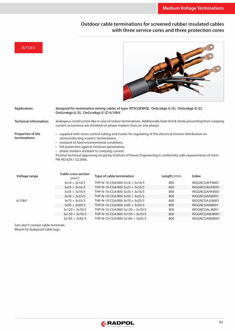
Medium Voltage Terminations
91
Outdoor cable terminations for screened rubber insulated cableswith three service cores and three protection cores
Sets don't contain cable terminals.Meant for leakproof cable lugs.
Voltage range Cable cross-section[mm2] Type of cable termination Length [mm] Index
6/10kV
3x16 + 3x16/3 THP-N-10-CG4/800 3x16 + 3x16/3 800 WGGNCGAFF80013x25 + 3x16/3 THP-N-10-CG4/800 3x25 + 3x16/3 800 WGGNCGAGF80013x35 + 3x16/3 THP-N-10-CG4/800 3x35 + 3x16/3 800 WGGNCGAHF80013x50 + 3x25/3 THP-N-10-CG4/800 3x50 + 3x25/3 800 WGGNCGAIG80013x70 + 3x35/3 THP-N-10-CG4/800 3x70 + 3x35/3 800 WGGNCGAJG80013x95 + 3x50/3 THP-N-10-CG4/800 3x95 + 3x50/3 800 WGGNCGAKI8001
3x120 + 3x70/3 THP-N-10-CG4/800 3x120 + 3x70/3 800 WGGNCGALJ80013x150 + 3x70/3 THP-N-10-CG4/800 3x150 + 3x70/3 800 WGGNCGAMJ80013x185 + 3x95/3 THP-N-10-CG4/800 3x185 + 3x95/3 800 WGGNCGANK8001
designed for termination mining cables of type: NTSCGEWOE, OnGcekgż-G (S), OnGcekgż-G (Z),OnGcrekgż-G (S), OnGcrekgż-G (Z) 6/10kV.
analogous construction like in case of indoor terminations. Additionally heat shrink sheds preventing from creepingcurrent occurrence are shrinked on phase markers (two on one phase).
• supplied with stress control tubing and mastic for regulating of the electrical tension distribution on semiconducting screens' terminations,
• resistant to hard environmental conditions,• full protection against moisture penetration,• phase markers resistant to creeping current.Positive technical approving issued by Institute of Power Engineering in conformity with requirements of normPN-HD 629.1 S2:2006.
6/10kV
Application:
Technical information:
Properties of theterminations:
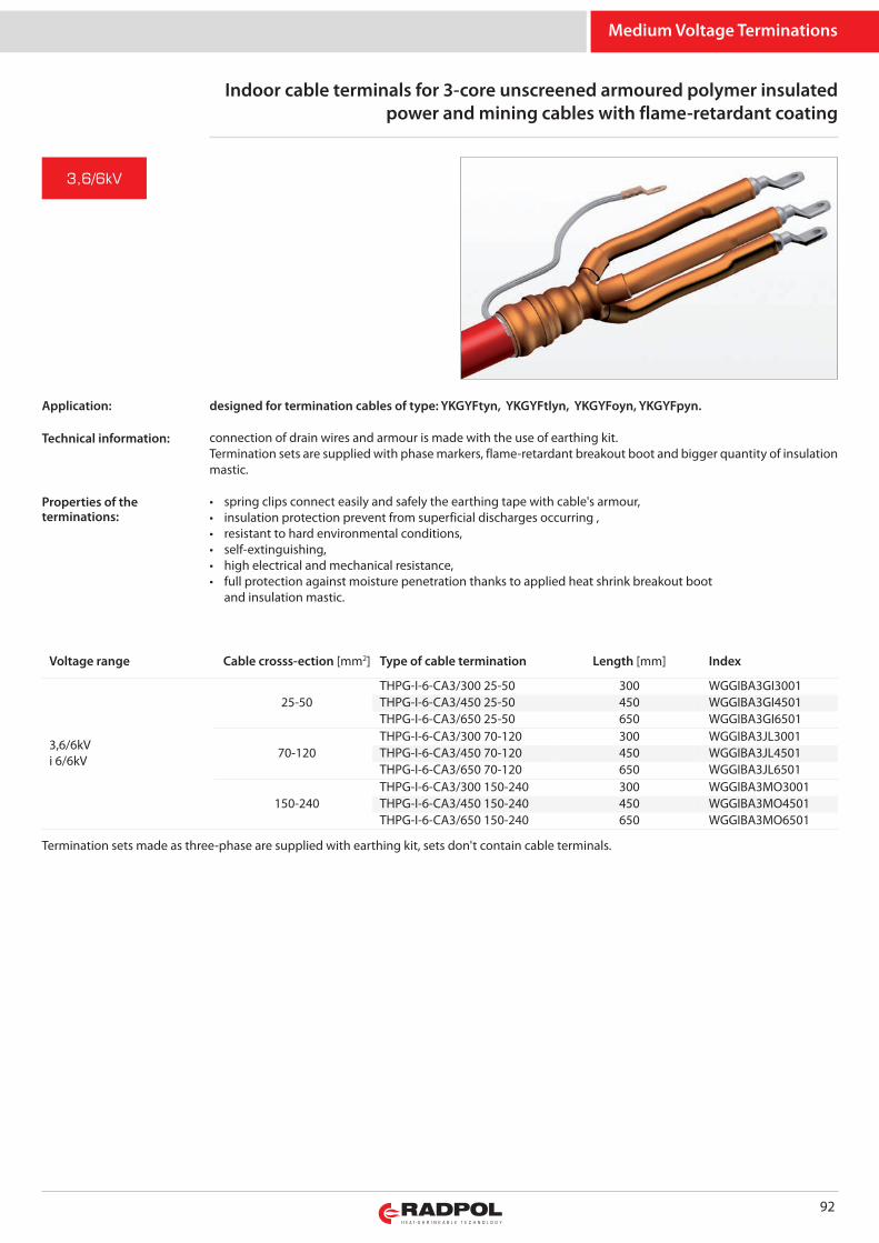
Medium Voltage Terminations
92
Indoor cable terminals for 3-core unscreened armoured polymer insulatedpower and mining cables with flame-retardant coating
Termination sets made as three-phase are supplied with earthing kit, sets don't contain cable terminals.
Voltage range Cable crosss-ection [mm2] Type of cable termination Length [mm] Index
3,6/6kVi 6/6kV
25-50THPG-I-6-CA3/300 25-50 300 WGGIBA3GI3001THPG-I-6-CA3/450 25-50 450 WGGIBA3GI4501THPG-I-6-CA3/650 25-50 650 WGGIBA3GI6501
70-120THPG-I-6-CA3/300 70-120 300 WGGIBA3JL3001THPG-I-6-CA3/450 70-120 450 WGGIBA3JL4501THPG-I-6-CA3/650 70-120 650 WGGIBA3JL6501
150-240THPG-I-6-CA3/300 150-240 300 WGGIBA3MO3001THPG-I-6-CA3/450 150-240 450 WGGIBA3MO4501THPG-I-6-CA3/650 150-240 650 WGGIBA3MO6501
3,6/6kV
designed for termination cables of type: YKGYFtyn, YKGYFtlyn, YKGYFoyn, YKGYFpyn.
connection of drain wires and armour is made with the use of earthing kit.Termination sets are supplied with phase markers, flame-retardant breakout boot and bigger quantity of insulationmastic.
• spring clips connect easily and safely the earthing tape with cable's armour,• insulation protection prevent from superficial discharges occurring ,• resistant to hard environmental conditions,• self-extinguishing,• high electrical and mechanical resistance,• full protection against moisture penetration thanks to applied heat shrink breakout boot
and insulation mastic.
Application:
Technical information:
Properties of theterminations:
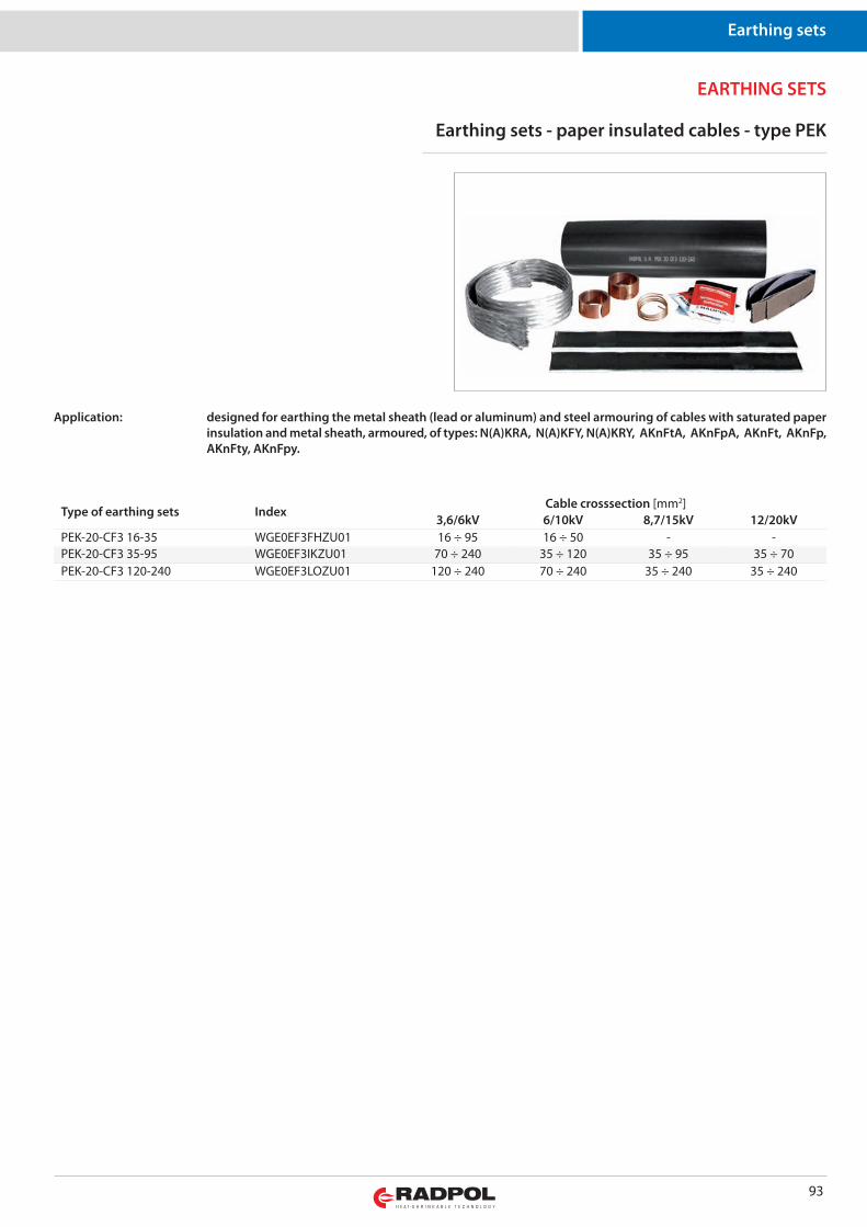
Earthing sets
93
Earthing sets - paper insulated cables - type PEK
Application: designed for earthing the metal sheath (lead or aluminum) and steel armouring of cables with saturated paperinsulation and metal sheath, armoured, of types: N(A)KRA, N(A)KFY, N(A)KRY, AKnFtA, AKnFpA, AKnFt, AKnFp,AKnFty, AKnFpy.
EARTHING SETS
Type of earthing sets IndexCable crosssection [mm2]
3,6/6kV 6/10kV 8,7/15kV 12/20kVPEK-20-CF3 16-35 WGE0EF3FHZU01 16 ÷ 95 16 ÷ 50 - -PEK-20-CF3 35-95 WGE0EF3IKZU01 70 ÷ 240 35 ÷ 120 35 ÷ 95 35 ÷ 70PEK-20-CF3 120-240 WGE0EF3LOZU01 120 ÷ 240 70 ÷ 240 35 ÷ 240 35 ÷ 240
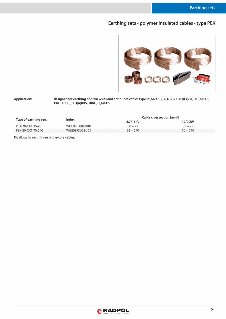
Earthing sets
94
Application: designed for earthing of drain wires and armour of cables type: N(A)2XS(2)Y, N(A)2XS(F)(L)(2)Y, YH(A)KXS,XUH(A)KXS, XH(A)KXS, X(RU)H(A)KXS.
Type of earthing sets IndexCable crosssection [mm2]
8,7/15kV 12/20kVPEK-20-CX1 35-95 WGE0EF3HKZU01 50 ÷ 95 35 ÷ 95PEK-20-CX1 70-240 WGE0EF3JOZU01 95 ÷ 240 70 ÷ 240
Earthing sets - polymer insulated cables - type PEK
Kit allows to earth three single-core cables.
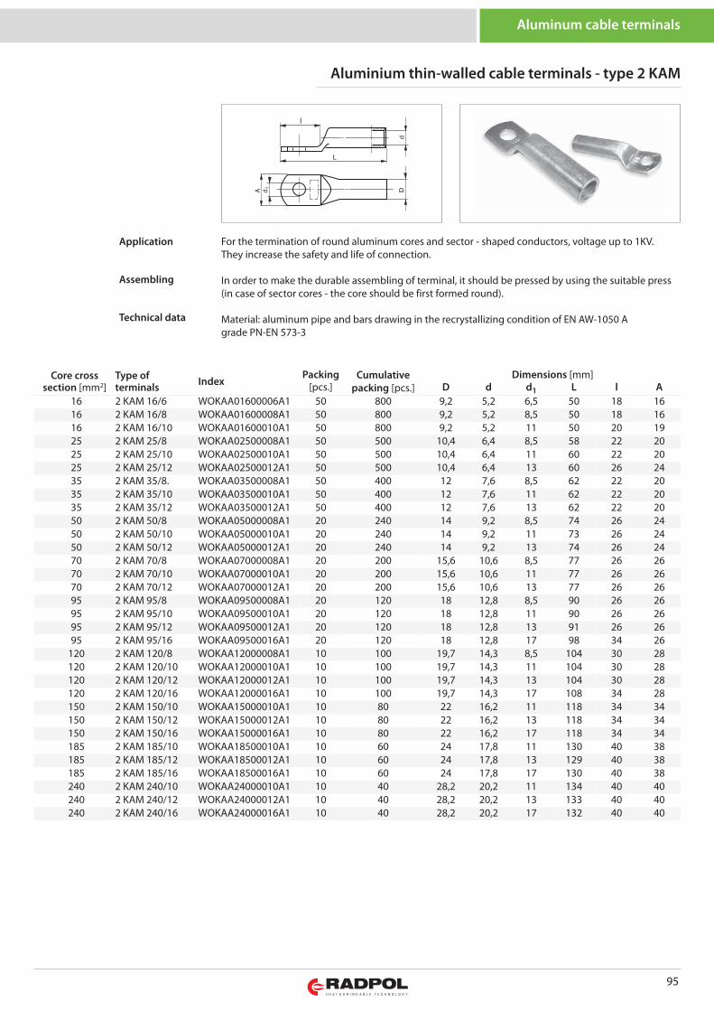
95
Aluminum cable terminals
Core crosssection [mm2]
Type ofterminals Index
Packing Cumulativepacking [pcs.]
Dimensions [mm][pcs.] D d d1 L l A
16 2 KAM 16/6 WOKAA01600006A1 50 800 9,2 5,2 6,5 50 18 1616 2 KAM 16/8 WOKAA01600008A1 50 800 9,2 5,2 8,5 50 18 1616 2 KAM 16/10 WOKAA01600010A1 50 800 9,2 5,2 11 50 20 1925 2 KAM 25/8 WOKAA02500008A1 50 500 10,4 6,4 8,5 58 22 2025 2 KAM 25/10 WOKAA02500010A1 50 500 10,4 6,4 11 60 22 2025 2 KAM 25/12 WOKAA02500012A1 50 500 10,4 6,4 13 60 26 2435 2 KAM 35/8. WOKAA03500008A1 50 400 12 7,6 8,5 62 22 2035 2 KAM 35/10 WOKAA03500010A1 50 400 12 7,6 11 62 22 2035 2 KAM 35/12 WOKAA03500012A1 50 400 12 7,6 13 62 22 2050 2 KAM 50/8 WOKAA05000008A1 20 240 14 9,2 8,5 74 26 2450 2 KAM 50/10 WOKAA05000010A1 20 240 14 9,2 11 73 26 2450 2 KAM 50/12 WOKAA05000012A1 20 240 14 9,2 13 74 26 2470 2 KAM 70/8 WOKAA07000008A1 20 200 15,6 10,6 8,5 77 26 2670 2 KAM 70/10 WOKAA07000010A1 20 200 15,6 10,6 11 77 26 2670 2 KAM 70/12 WOKAA07000012A1 20 200 15,6 10,6 13 77 26 2695 2 KAM 95/8 WOKAA09500008A1 20 120 18 12,8 8,5 90 26 2695 2 KAM 95/10 WOKAA09500010A1 20 120 18 12,8 11 90 26 2695 2 KAM 95/12 WOKAA09500012A1 20 120 18 12,8 13 91 26 2695 2 KAM 95/16 WOKAA09500016A1 20 120 18 12,8 17 98 34 26
120 2 KAM 120/8 WOKAA12000008A1 10 100 19,7 14,3 8,5 104 30 28120 2 KAM 120/10 WOKAA12000010A1 10 100 19,7 14,3 11 104 30 28120 2 KAM 120/12 WOKAA12000012A1 10 100 19,7 14,3 13 104 30 28120 2 KAM 120/16 WOKAA12000016A1 10 100 19,7 14,3 17 108 34 28150 2 KAM 150/10 WOKAA15000010A1 10 80 22 16,2 11 118 34 34150 2 KAM 150/12 WOKAA15000012A1 10 80 22 16,2 13 118 34 34150 2 KAM 150/16 WOKAA15000016A1 10 80 22 16,2 17 118 34 34185 2 KAM 185/10 WOKAA18500010A1 10 60 24 17,8 11 130 40 38185 2 KAM 185/12 WOKAA18500012A1 10 60 24 17,8 13 129 40 38185 2 KAM 185/16 WOKAA18500016A1 10 60 24 17,8 17 130 40 38240 2 KAM 240/10 WOKAA24000010A1 10 40 28,2 20,2 11 134 40 40240 2 KAM 240/12 WOKAA24000012A1 10 40 28,2 20,2 13 133 40 40240 2 KAM 240/16 WOKAA24000016A1 10 40 28,2 20,2 17 132 40 40
For the termination of round aluminum cores and sector - shaped conductors, voltage up to 1KV. They increase the safety and life of connection.
In order to make the durable assembling of terminal, it should be pressed by using the suitable press(in case of sector cores - the core should be first formed round).
Material: aluminum pipe and bars drawing in the recrystallizing condition of EN AW-1050 Agrade PN-EN 573-3
Application
Assembling
Technical data
Aluminium thin-walled cable terminals - type 2 KAM
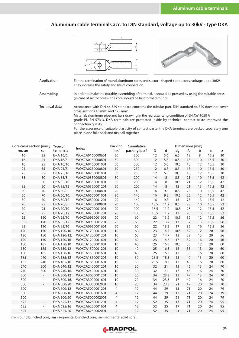
Aluminum cable terminals
96
Core cross section [mm2] Type ofterminals Index
Packing Cumulativepacking [pcs.]
Dimensions [mm]rm, sm se [pcs.] D d d1 A b c z
16 25 DKA 16/6. WOKCA0160000601 50 300 12 5,6 6,5 18 8 15,5 3016 25 DKA 16/8 WOKCA0160000801 50 300 12 5,6 8,5 18 10 15,5 3016 25 DKA 16/10 WOKCA0160001001 50 300 12 5,6 10,5 18 12 15,5 3025 35 DKA 25/8. WOKCA0250000801 50 250 12 6,8 8,5 18 10 15,5 3025 35 DKA 25/10 WOKCA0250001001 50 250 12 6,8 10,5 18 12 15,5 3035 50 DKA 35/8 WOKCA0350000801 50 200 14 8 8,5 21 10 15,5 4235 50 DKA 35/10. WOKCA0350001001 50 200 14 8 10,5 21 12 15,5 4235 50 DKA 35/12 WOKCA0350001201 50 200 14 8 13 21 13 15,5 4250 70 DKA 50/8 WOKCA0500000801 20 140 16 9,8 8,5 25 10 15,5 4250 70 DKA 50/10. WOKCA0500001001 20 140 16 9,8 10,5 25 12 15,5 4250 70 DKA 50/12 WOKCA0500001201 20 140 16 9,8 13 25 13 15,5 4270 95 DKA 70/8 WOKCA0700000801 20 100 18,5 11,2 8,5 28 10 15,5 5270 95 DKA 70/10 WOKCA0700001001 20 100 18,5 11,2 10,5 28 12 15,5 5270 95 DKA 70/12. WOKCA0700001201 20 100 18,5 11,2 13 28 13 15,5 5295 120 DKA 95/10 WOKCA0950001001 20 60 22 13,2 10,5 32 12 15,5 5695 120 DKA 95/12. WOKCA0950001201 20 60 22 13,2 13 32 13 15,5 5695 120 DKA 95/16 WOKCA0950001601 20 60 22 13,2 17 32 16 15,5 56
120 150 DKA 120/10 WOKCA1200001001 10 60 23 14,7 10,5 32 12 20 56120 150 DKA 120/12. WOKCA1200001201 10 60 23 14,7 13 32 13 20 56120 150 DKA 120/16 WOKCA1200001601 10 60 23 14,7 17 32 16 20 56150 185 DKA 150/10 WOKCA1500001001 10 40 25 16,3 10,5 35 12 20 60150 185 DKA 150/12 WOKCA1500001201 10 40 25 16,3 13 35 13 20 60150 185 DKA 150/16. WOKCA1500001601 10 40 25 16,3 17 35 16 20 60185 240 DKA 185/12 WOKCA1850001201 10 30 28,5 18,3 13 40 13 20 60185 240 DKA 185/16. WOKCA1850001601 10 30 28,5 18,3 17 40 16 20 60240 300 DKA 240/12 WOKCA2400001201 10 30 32 21 13 45 13 24 70240 300 DKA 240/16. WOKCA2400001601 10 30 32 21 17 45 16 24 70300 - DKA 300/12 WOKCA3000001201 10 20 34 23,3 13 49 13 24 70300 - DKA 300/16. WOKCA3000001601 10 20 34 23,3 17 49 16 24 70300 - DKA 300/20 WOKCA3000002001 10 20 34 23,3 21 49 20 24 70500 DKA 500/12 WOKCA5000001201 4 12 44 29 13 71 20 24 79500 DKA 500/16 WOKCA5000001601 4 12 44 29 17 71 20 24 79500 DKA 500/20 WOKCA5000002001 4 12 44 29 21 71 20 24 79625 - DKA 625/12 WOKCA6250001201 4 12 52 35 13 71 20 24 95625 - DKA 625/16 WOKCA6250001601 4 12 52 35 17 71 20 24 95625 - DKA 625/20 WOKCA6250002001 4 12 52 35 21 71 20 24 95
z
b c
Aluminium cable terminals acc. to DIN standard, voltage up to 30kV - type DKA
For the termination of round aluminum cores and sector - shaped conductors, voltage up to 30KV. They increase the safety and life of connection.
In order to make the durable assembling of terminal, it should be pressed by using the suitable press(in case of sector cores - the core should be first formed round).
Accordance with DIN 46 329 standard concerns the tubular part. DIN standard 46 329 does not covercross-sections 16 mm2 and 625 mm2. Material: aluminum pipe and bars drawing in the recrystallizing condition of EN AW-1050 Agrade PN-EN 573-3. DKA terminals are protected inside by technical contact paste improved theconnection quality. For the assurance of suitable plasticity of contact paste, the DKA terminals are packed separately onepiece in one folie sack and next all together.
Application
Assembling
Technical data
rm - round bunched core, sm - segmental bunched core, se - segmental solid core.
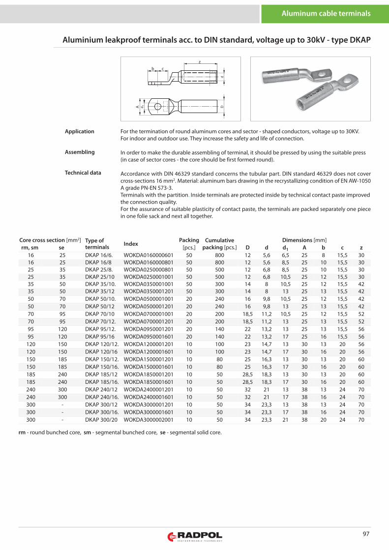
97
Aluminum cable terminals
Core cross section [mm2] Type ofterminals Index
Packing Cumulativepacking [pcs.]
Dimensions [mm]rm, sm se [pcs.] D d d1 A b c z
16 25 DKAP 16/6. WOKDA0160000601 50 800 12 5,6 6,5 25 8 15,5 3016 25 DKAP 16/8 WOKDA0160000801 50 800 12 5,6 8,5 25 10 15,5 3025 35 DKAP 25/8. WOKDA0250000801 50 500 12 6,8 8,5 25 10 15,5 3025 35 DKAP 25/10 WOKDA0250001001 50 500 12 6,8 10,5 25 12 15,5 3035 50 DKAP 35/10. WOKDA0350001001 50 300 14 8 10,5 25 12 15,5 4235 50 DKAP 35/12 WOKDA0350001201 50 300 14 8 13 25 13 15,5 4250 70 DKAP 50/10. WOKDA0500001001 20 240 16 9,8 10,5 25 12 15,5 4250 70 DKAP 50/12 WOKDA0500001201 20 240 16 9,8 13 25 13 15,5 4270 95 DKAP 70/10 WOKDA0700001001 20 200 18,5 11,2 10,5 25 12 15,5 5270 95 DKAP 70/12. WOKDA0700001201 20 200 18,5 11,2 13 25 13 15,5 5295 120 DKAP 95/12. WOKDA0950001201 20 140 22 13,2 13 25 13 15,5 5695 120 DKAP 95/16 WOKDA0950001601 20 140 22 13,2 17 25 16 15,5 56
120 150 DKAP 120/12. WOKDA1200001201 10 100 23 14,7 13 30 13 20 56120 150 DKAP 120/16 WOKDA1200001601 10 100 23 14,7 17 30 16 20 56150 185 DKAP 150/12. WOKDA1500001201 10 80 25 16,3 13 30 13 20 60150 185 DKAP 150/16. WOKDA1500001601 10 80 25 16,3 17 30 16 20 60185 240 DKAP 185/12 WOKDA1850001201 10 50 28,5 18,3 13 30 13 20 60185 240 DKAP 185/16. WOKDA1850001601 10 50 28,5 18,3 17 30 16 20 60240 300 DKAP 240/12 WOKDA2400001201 10 50 32 21 13 38 13 24 70240 300 DKAP 240/16. WOKDA2400001601 10 50 32 21 17 38 16 24 70300 - DKAP 300/12 WOKDA3000001201 10 50 34 23,3 13 38 13 24 70300 - DKAP 300/16. WOKDA3000001601 10 50 34 23,3 17 38 16 24 70300 - DKAP 300/20 WOKDA3000002001 10 50 34 23,3 21 38 20 24 70
b c
z
Aluminium leakproof terminals acc. to DIN standard, voltage up to 30kV - type DKAP
For the termination of round aluminum cores and sector - shaped conductors, voltage up to 30KV. For indoor and outdoor use. They increase the safety and life of connection.
In order to make the durable assembling of terminal, it should be pressed by using the suitable press(in case of sector cores - the core should be first formed round).
Accordance with DIN 46329 standard concerns the tubular part. DIN standard 46329 does not covercross-sections 16 mm2. Material: aluminum bars drawing in the recrystallizing condition of EN AW-1050A grade PN-EN 573-3. Terminals with the partition. Inside terminals are protected inside by technical contact paste improvedthe connection quality. For the assurance of suitable plasticity of contact paste, the terminals are packed separately one piecein one folie sack and next all together.
Application
Assembling
Technical data
rm - round bunched core, sm - segmental bunched core, se - segmental solid core.
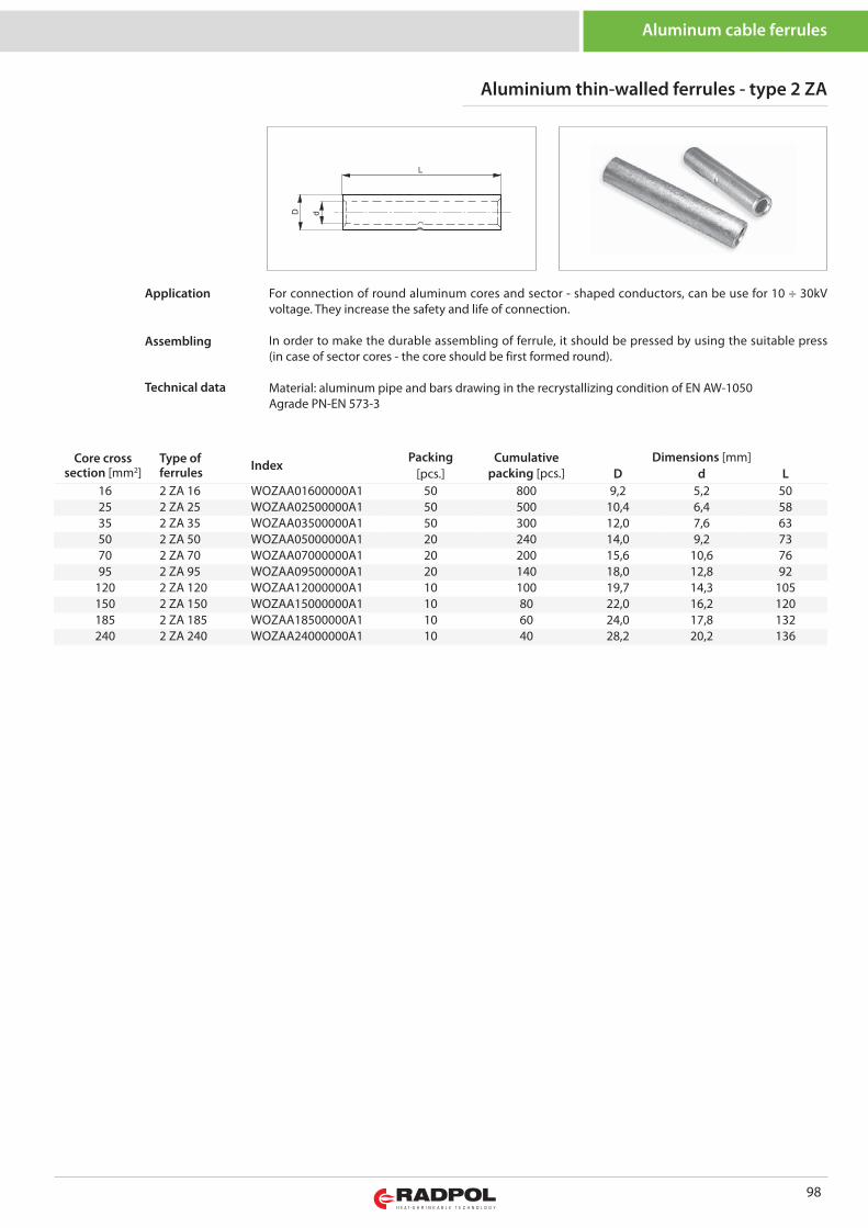
98
Aluminum cable ferrules
Core crosssection [mm2]
Type offerrules Index
Packing Cumulativepacking [pcs.]
Dimensions [mm][pcs.] D d L
16 2 ZA 16 WOZAA01600000A1 50 800 9,2 5,2 5025 2 ZA 25 WOZAA02500000A1 50 500 10,4 6,4 5835 2 ZA 35 WOZAA03500000A1 50 300 12,0 7,6 6350 2 ZA 50 WOZAA05000000A1 20 240 14,0 9,2 7370 2 ZA 70 WOZAA07000000A1 20 200 15,6 10,6 7695 2 ZA 95 WOZAA09500000A1 20 140 18,0 12,8 92
120 2 ZA 120 WOZAA12000000A1 10 100 19,7 14,3 105150 2 ZA 150 WOZAA15000000A1 10 80 22,0 16,2 120185 2 ZA 185 WOZAA18500000A1 10 60 24,0 17,8 132240 2 ZA 240 WOZAA24000000A1 10 40 28,2 20,2 136
Aluminium thin-walled ferrules - type 2 ZA
For connection of round aluminum cores and sector - shaped conductors, can be use for 10 ÷ 30kVvoltage. They increase the safety and life of connection.
In order to make the durable assembling of ferrule, it should be pressed by using the suitable press(in case of sector cores - the core should be first formed round).
Material: aluminum pipe and bars drawing in the recrystallizing condition of EN AW-1050Agrade PN-EN 573-3
Application
Assembling
Technical data
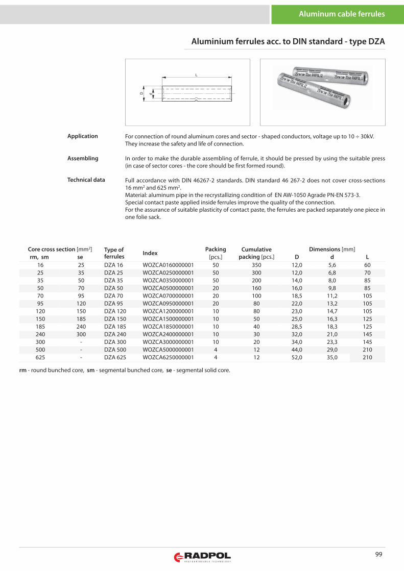
99
Aluminum cable ferrules
Core cross section [mm2] Type offerrules Index
Packing Cumulativepacking [pcs.]
Dimensions [mm]rm, sm se [pcs.] D d L
16 25 DZA 16 WOZCA0160000001 50 350 12,0 5,6 6025 35 DZA 25 WOZCA0250000001 50 300 12,0 6,8 7035 50 DZA 35 WOZCA0350000001 50 200 14,0 8,0 8550 70 DZA 50 WOZCA0500000001 20 160 16,0 9,8 8570 95 DZA 70 WOZCA0700000001 20 100 18,5 11,2 10595 120 DZA 95 WOZCA0950000001 20 80 22,0 13,2 105
120 150 DZA 120 WOZCA1200000001 10 80 23,0 14,7 105150 185 DZA 150 WOZCA1500000001 10 50 25,0 16,3 125185 240 DZA 185 WOZCA1850000001 10 40 28,5 18,3 125240 300 DZA 240 WOZCA2400000001 10 30 32,0 21,0 145300 - DZA 300 WOZCA3000000001 10 20 34,0 23,3 145500 - DZA 500 WOZCA5000000001 4 12 44,0 29,0 210625 - DZA 625 WOZCA6250000001 4 12 52,0 35,0 210
rm - round bunched core, sm - segmental bunched core, se - segmental solid core.
Aluminium ferrules acc. to DIN standard - type DZA
For connection of round aluminum cores and sector - shaped conductors, voltage up to 10 ÷ 30kV. They increase the safety and life of connection.
In order to make the durable assembling of ferrule, it should be pressed by using the suitable press(in case of sector cores - the core should be first formed round).
Full accordance with DIN 46267-2 standards. DIN standard 46 267-2 does not cover cross-sections16 mm2 and 625 mm2. Material: aluminum pipe in the recrystallizing condition of EN AW-1050 Agrade PN-EN 573-3. Special contact paste applied inside ferrules improve the quality of the connection. For the assurance of suitable plasticity of contact paste, the ferrules are packed separately one piece inone folie sack.
Application
Assembling
Technical data
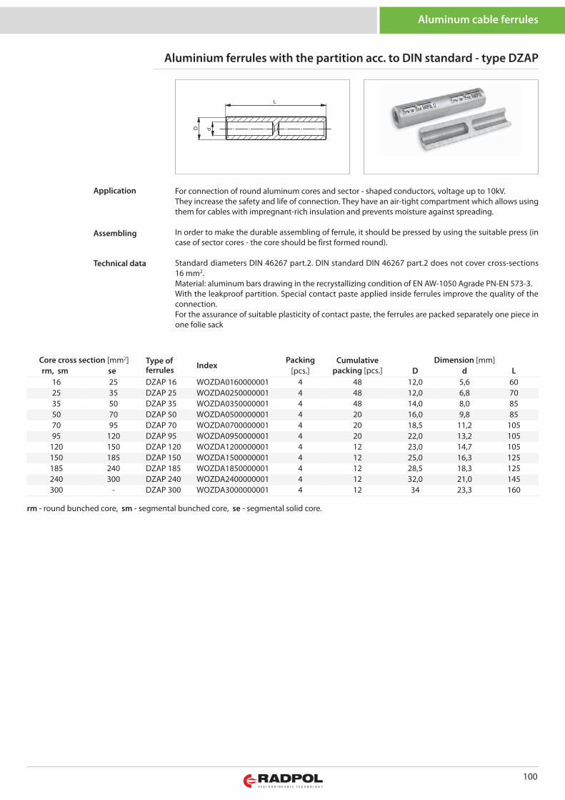
100
Aluminum cable ferrules
Core cross section [mm2] Type offerrules Index
Packing Cumulativepacking [pcs.]
Dimension [mm]rm, sm se [pcs.] D d L
16 25 DZAP 16 WOZDA0160000001 4 48 12,0 5,6 6025 35 DZAP 25 WOZDA0250000001 4 48 12,0 6,8 7035 50 DZAP 35 WOZDA0350000001 4 48 14,0 8,0 8550 70 DZAP 50 WOZDA0500000001 4 20 16,0 9,8 8570 95 DZAP 70 WOZDA0700000001 4 20 18,5 11,2 10595 120 DZAP 95 WOZDA0950000001 4 20 22,0 13,2 105
120 150 DZAP 120 WOZDA1200000001 4 12 23,0 14,7 105150 185 DZAP 150 WOZDA1500000001 4 12 25,0 16,3 125185 240 DZAP 185 WOZDA1850000001 4 12 28,5 18,3 125240 300 DZAP 240 WOZDA2400000001 4 12 32,0 21,0 145300 - DZAP 300 WOZDA3000000001 4 12 34 23,3 160
rm - round bunched core, sm - segmental bunched core, se - segmental solid core.
Aluminium ferrules with the partition acc. to DIN standard - type DZAP
For connection of round aluminum cores and sector - shaped conductors, voltage up to 10kV. They increase the safety and life of connection. They have an air-tight compartment which allows usingthem for cables with impregnant-rich insulation and prevents moisture against spreading.
In order to make the durable assembling of ferrule, it should be pressed by using the suitable press (incase of sector cores - the core should be first formed round).
Standard diameters DIN 46267 part.2. DIN standard DIN 46267 part.2 does not cover cross-sections16 mm2. Material: aluminum bars drawing in the recrystallizing condition of EN AW-1050 Agrade PN-EN 573-3. With the leakproof partition. Special contact paste applied inside ferrules improve the quality of theconnection. For the assurance of suitable plasticity of contact paste, the ferrules are packed separately one piece inone folie sack
Application
Assembling
Technical data
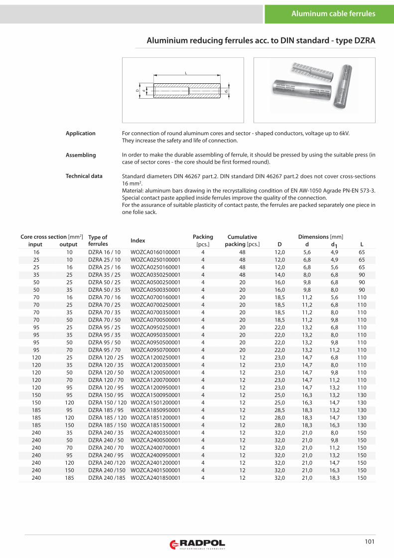
101
Aluminum cable ferrules
Core cross section [mm2] Type offerrules Index
Packing Cumulativepacking [pcs.]
Dimensions [mm]input output [pcs.] D d d1 L
16 10 DZRA 16 / 10 WOZCA0160100001 4 48 12,0 5,6 4,9 6525 10 DZRA 25 / 10 WOZCA0250100001 4 48 12,0 6,8 4,9 6525 16 DZRA 25 / 16 WOZCA0250160001 4 48 12,0 6,8 5,6 6535 25 DZRA 35 / 25 WOZCA0350250001 4 48 14,0 8,0 6,8 9050 25 DZRA 50 / 25 WOZCA0500250001 4 20 16,0 9,8 6,8 9050 35 DZRA 50 / 35 WOZCA0500350001 4 20 16,0 9,8 8,0 9070 16 DZRA 70 / 16 WOZCA0700160001 4 20 18,5 11,2 5,6 11070 25 DZRA 70 / 25 WOZCA0700250001 4 20 18,5 11,2 6,8 11070 35 DZRA 70 / 35 WOZCA0700350001 4 20 18,5 11,2 8,0 11070 50 DZRA 70 / 50 WOZCA0700500001 4 20 18,5 11,2 9,8 11095 25 DZRA 95 / 25 WOZCA0950250001 4 20 22,0 13,2 6,8 11095 35 DZRA 95 / 35 WOZCA0950350001 4 20 22,0 13,2 8,0 11095 50 DZRA 95 / 50 WOZCA0950500001 4 20 22,0 13,2 9,8 11095 70 DZRA 95 / 70 WOZCA0950700001 4 20 22,0 13,2 11,2 110
120 25 DZRA 120 / 25 WOZCA1200250001 4 12 23,0 14,7 6,8 110120 35 DZRA 120 / 35 WOZCA1200350001 4 12 23,0 14,7 8,0 110120 50 DZRA 120 / 50 WOZCA1200500001 4 12 23,0 14,7 9,8 110120 70 DZRA 120 / 70 WOZCA1200700001 4 12 23,0 14,7 11,2 110120 95 DZRA 120 / 95 WOZCA1200950001 4 12 23,0 14,7 13,2 110150 95 DZRA 150 / 95 WOZCA1500950001 4 12 25,0 16,3 13,2 130150 120 DZRA 150 / 120 WOZCA1501200001 4 12 25,0 16,3 14,7 130185 95 DZRA 185 / 95 WOZCA1850950001 4 12 28,5 18,3 13,2 130185 120 DZRA 185 / 120 WOZCA1851200001 4 12 28,0 18,3 14,7 130185 150 DZRA 185 / 150 WOZCA1851500001 4 12 28,0 18,3 16,3 130240 35 DZRA 240 / 35 WOZCA2400350001 4 12 32,0 21,0 8,0 150240 50 DZRA 240 / 50 WOZCA2400500001 4 12 32,0 21,0 9,8 150240 70 DZRA 240 / 70 WOZCA2400700001 4 12 32,0 21,0 11,2 150240 95 DZRA 240 / 95 WOZCA2400950001 4 12 32,0 21,0 13,2 150240 120 DZRA 240 /120 WOZCA2401200001 4 12 32,0 21,0 14,7 150240 150 DZRA 240 /150 WOZCA2401500001 4 12 32,0 21,0 16,3 150240 185 DZRA 240 /185 WOZCA2401850001 4 12 32,0 21,0 18,3 150
Aluminium reducing ferrules acc. to DIN standard - type DZRA
For connection of round aluminum cores and sector - shaped conductors, voltage up to 6kV. They increase the safety and life of connection.
In order to make the durable assembling of ferrule, it should be pressed by using the suitable press (incase of sector cores - the core should be first formed round).
Standard diameters DIN 46267 part.2. DIN standard DIN 46267 part.2 does not cover cross-sections16 mm2.Material: aluminum bars drawing in the recrystallizing condition of EN AW-1050 Agrade PN-EN 573-3.Special contact paste applied inside ferrules improve the quality of the connection. For the assurance of suitable plasticity of contact paste, the ferrules are packed separately one piece inone folie sack.
Application
Assembling
Technical data
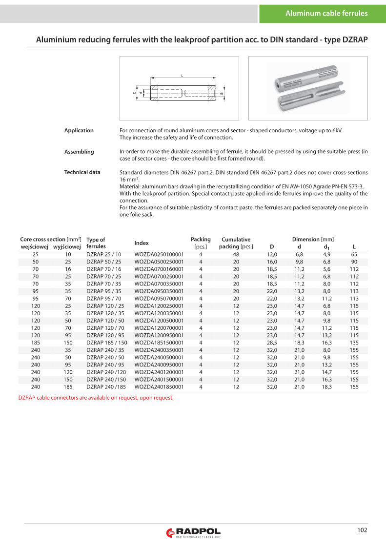
102
Aluminum cable ferrules
For connection of round aluminum cores and sector - shaped conductors, voltage up to 6kV. They increase the safety and life of connection.
In order to make the durable assembling of ferrule, it should be pressed by using the suitable press (incase of sector cores - the core should be first formed round).
Standard diameters DIN 46267 part.2. DIN standard DIN 46267 part.2 does not cover cross-sections16 mm2.Material: aluminum bars drawing in the recrystallizing condition of EN AW-1050 Agrade PN-EN 573-3.With the leakproof partition. Special contact paste applied inside ferrules improve the quality of theconnection. For the assurance of suitable plasticity of contact paste, the ferrules are packed separately one piece inone folie sack.
Application
Assembling
Technical data
Core cross section [mm2] Type offerrules Index
Packing Cumulativepacking [pcs.]
Dimension [mm]wejściowej wyjściowej [pcs.] D d d1 L
25 10 DZRAP 25 / 10 WOZDA0250100001 4 48 12,0 6,8 4,9 6550 25 DZRAP 50 / 25 WOZDA0500250001 4 20 16,0 9,8 6,8 9070 16 DZRAP 70 / 16 WOZDA0700160001 4 20 18,5 11,2 5,6 11270 25 DZRAP 70 / 25 WOZDA0700250001 4 20 18,5 11,2 6,8 11270 35 DZRAP 70 / 35 WOZDA0700350001 4 20 18,5 11,2 8,0 11295 35 DZRAP 95 / 35 WOZDA0950350001 4 20 22,0 13,2 8,0 11395 70 DZRAP 95 / 70 WOZDA0950700001 4 20 22,0 13,2 11,2 113
120 25 DZRAP 120 / 25 WOZDA1200250001 4 12 23,0 14,7 6,8 115120 35 DZRAP 120 / 35 WOZDA1200350001 4 12 23,0 14,7 8,0 115120 50 DZRAP 120 / 50 WOZDA1200500001 4 12 23,0 14,7 9,8 115120 70 DZRAP 120 / 70 WOZDA1200700001 4 12 23,0 14,7 11,2 115120 95 DZRAP 120 / 95 WOZDA1200950001 4 12 23,0 14,7 13,2 115185 150 DZRAP 185 / 150 WOZDA1851500001 4 12 28,5 18,3 16,3 135240 35 DZRAP 240 / 35 WOZDA2400350001 4 12 32,0 21,0 8,0 155240 50 DZRAP 240 / 50 WOZDA2400500001 4 12 32,0 21,0 9,8 155240 95 DZRAP 240 / 95 WOZDA2400950001 4 12 32,0 21,0 13,2 155240 120 DZRAP 240 /120 WOZDA2401200001 4 12 32,0 21,0 14,7 155240 150 DZRAP 240 /150 WOZDA2401500001 4 12 32,0 21,0 16,3 155240 185 DZRAP 240 /185 WOZDA2401850001 4 12 32,0 21,0 18,3 155
Aluminium reducing ferrules with the leakproof partition acc. to DIN standard - type DZRAP
DZRAP cable connectors are available on request, upon request.
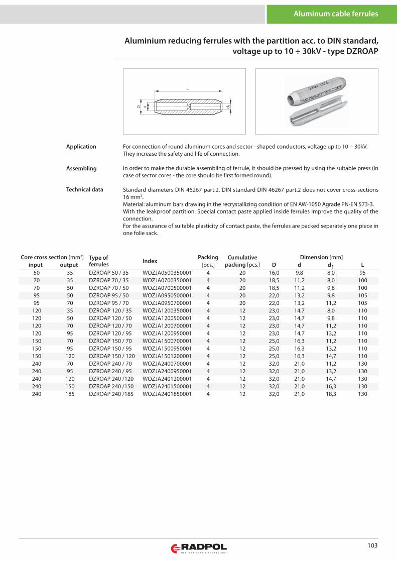
103
Core cross section [mm2] Type offerrules Index
Packing Cumulativepacking [pcs.]
Dimension [mm]input output [pcs.] D d d1 L
50 35 DZROAP 50 / 35 WOZJA0500350001 4 20 16,0 9,8 8,0 9570 35 DZROAP 70 / 35 WOZJA0700350001 4 20 18,5 11,2 8,0 10070 50 DZROAP 70 / 50 WOZJA0700500001 4 20 18,5 11,2 9,8 10095 50 DZROAP 95 / 50 WOZJA0950500001 4 20 22,0 13,2 9,8 10595 70 DZROAP 95 / 70 WOZJA0950700001 4 20 22,0 13,2 11,2 105
120 35 DZROAP 120 / 35 WOZJA1200350001 4 12 23,0 14,7 8,0 110120 50 DZROAP 120 / 50 WOZJA1200500001 4 12 23,0 14,7 9,8 110120 70 DZROAP 120 / 70 WOZJA1200700001 4 12 23,0 14,7 11,2 110120 95 DZROAP 120 / 95 WOZJA1200950001 4 12 23,0 14,7 13,2 110150 70 DZROAP 150 / 70 WOZJA1500700001 4 12 25,0 16,3 11,2 110150 95 DZROAP 150 / 95 WOZJA1500950001 4 12 25,0 16,3 13,2 110150 120 DZROAP 150 / 120 WOZJA1501200001 4 12 25,0 16,3 14,7 110240 70 DZROAP 240 / 70 WOZJA2400700001 4 12 32,0 21,0 11,2 130240 95 DZROAP 240 / 95 WOZJA2400950001 4 12 32,0 21,0 13,2 130240 120 DZROAP 240 /120 WOZJA2401200001 4 12 32,0 21,0 14,7 130240 150 DZROAP 240 /150 WOZJA2401500001 4 12 32,0 21,0 16,3 130240 185 DZROAP 240 /185 WOZJA2401850001 4 12 32,0 21,0 18,3 130
Aluminium reducing ferrules with the partition acc. to DIN standard,voltage up to 10 ÷ 30kV - type DZROAP
Aluminum cable ferrules
For connection of round aluminum cores and sector - shaped conductors, voltage up to 10 ÷ 30kV. They increase the safety and life of connection.
In order to make the durable assembling of ferrule, it should be pressed by using the suitable press (incase of sector cores - the core should be first formed round).
Standard diameters DIN 46267 part.2. DIN standard DIN 46267 part.2 does not cover cross-sections16 mm2.Material: aluminum bars drawing in the recrystallizing condition of EN AW-1050 Agrade PN-EN 573-3.With the leakproof partition. Special contact paste applied inside ferrules improve the quality of theconnection. For the assurance of suitable plasticity of contact paste, the ferrules are packed separately one piece inone folie sack.
Application
Assembling
Technical data
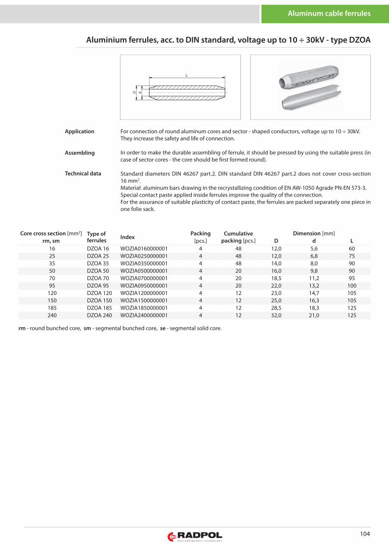
104
Core cross section [mm2] Type offerrules Index
Packing Cumulativepacking [pcs.]
Dimension [mm]rm, sm [pcs.] D d L
16 DZOA 16 WOZIA0160000001 4 48 12,0 5,6 6025 DZOA 25 WOZIA0250000001 4 48 12,0 6,8 7535 DZOA 35 WOZIA0350000001 4 48 14,0 8,0 9050 DZOA 50 WOZIA0500000001 4 20 16,0 9,8 9070 DZOA 70 WOZIA0700000001 4 20 18,5 11,2 9595 DZOA 95 WOZIA0950000001 4 20 22,0 13,2 100
120 DZOA 120 WOZIA1200000001 4 12 23,0 14,7 105150 DZOA 150 WOZIA1500000001 4 12 25,0 16,3 105185 DZOA 185 WOZIA1850000001 4 12 28,5 18,3 125240 DZOA 240 WOZIA2400000001 4 12 32,0 21,0 125
rm - round bunched core, sm - segmental bunched core, se - segmental solid core.
Aluminium ferrules, acc. to DIN standard, voltage up to 10 ÷ 30kV - type DZOA
Aluminum cable ferrules
For connection of round aluminum cores and sector - shaped conductors, voltage up to 10 ÷ 30kV. They increase the safety and life of connection.
In order to make the durable assembling of ferrule, it should be pressed by using the suitable press (incase of sector cores - the core should be first formed round).
Standard diameters DIN 46267 part.2. DIN standard DIN 46267 part.2 does not cover cross-section16 mm2. Material: aluminum bars drawing in the recrystallizing condition of EN AW-1050 Agrade PN-EN 573-3.Special contact paste applied inside ferrules improve the quality of the connection. For the assurance of suitable plasticity of contact paste, the ferrules are packed separately one piece inone folie sack.
Application
Assembling
Technical data
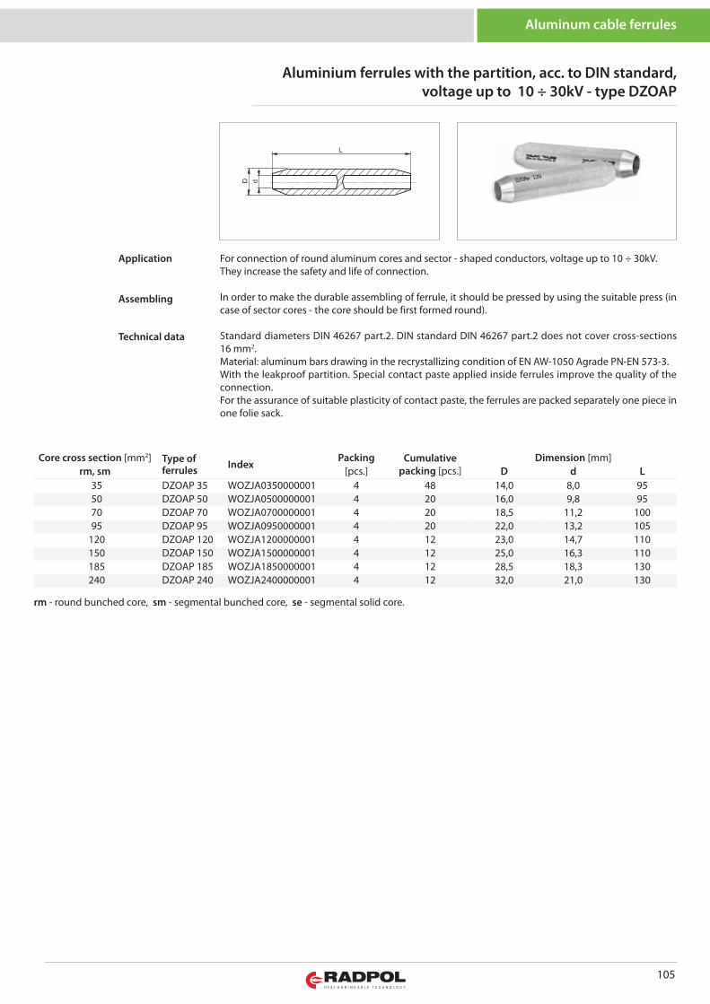
105
Core cross section [mm2] Type offerrules Index
Packing Cumulativepacking [pcs.]
Dimension [mm]rm, sm [pcs.] D d L
35 DZOAP 35 WOZJA0350000001 4 48 14,0 8,0 9550 DZOAP 50 WOZJA0500000001 4 20 16,0 9,8 9570 DZOAP 70 WOZJA0700000001 4 20 18,5 11,2 10095 DZOAP 95 WOZJA0950000001 4 20 22,0 13,2 105
120 DZOAP 120 WOZJA1200000001 4 12 23,0 14,7 110150 DZOAP 150 WOZJA1500000001 4 12 25,0 16,3 110185 DZOAP 185 WOZJA1850000001 4 12 28,5 18,3 130240 DZOAP 240 WOZJA2400000001 4 12 32,0 21,0 130
rm - round bunched core, sm - segmental bunched core, se - segmental solid core.
Aluminium ferrules with the partition, acc. to DIN standard, voltage up to 10 ÷ 30kV - type DZOAP
Aluminum cable ferrules
For connection of round aluminum cores and sector - shaped conductors, voltage up to 10 ÷ 30kV. They increase the safety and life of connection.
In order to make the durable assembling of ferrule, it should be pressed by using the suitable press (incase of sector cores - the core should be first formed round).
Standard diameters DIN 46267 part.2. DIN standard DIN 46267 part.2 does not cover cross-sections16 mm2. Material: aluminum bars drawing in the recrystallizing condition of EN AW-1050 Agrade PN-EN 573-3.With the leakproof partition. Special contact paste applied inside ferrules improve the quality of theconnection. For the assurance of suitable plasticity of contact paste, the ferrules are packed separately one piece inone folie sack.
Application
Assembling
Technical data
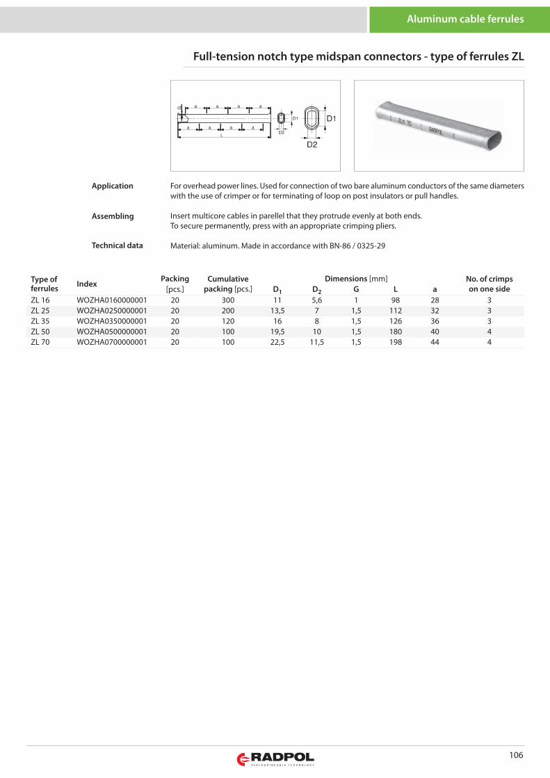
106
Type offerrules Index
Packing Cumulativepacking [pcs.]
Dimensions [mm] No. of crimpson one side[pcs.] D1 D2 G L a
ZL 16 WOZHA0160000001 20 300 11 5,6 1 98 28 3ZL 25 WOZHA0250000001 20 200 13,5 7 1,5 112 32 3ZL 35 WOZHA0350000001 20 120 16 8 1,5 126 36 3ZL 50 WOZHA0500000001 20 100 19,5 10 1,5 180 40 4ZL 70 WOZHA0700000001 20 100 22,5 11,5 1,5 198 44 4
Full-tension notch type midspan connectors - type of ferrules ZL
Aluminum cable ferrules
For overhead power lines. Used for connection of two bare aluminum conductors of the same diameterswith the use of crimper or for terminating of loop on post insulators or pull handles.
Insert multicore cables in parellel that they protrude evenly at both ends.To secure permanently, press with an appropriate crimping pliers.
Material: aluminum. Made in accordance with BN-86 / 0325-29
Application
Assembling
Technical data
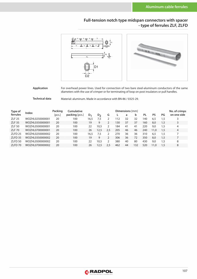
107
Full-tension notch type midspan connectors with spacer- type of ferrules ZLF, ZLFD
Type offerrules Index
Packing Cumulativepacking [pcs.]
Dimensions [mm] No. of crimpson one side[pcs.] D1 D2 G L a b PL PS PG
ZLF 25 WOZHL0250000001 20 100 16,5 7,5 2 112 32 32 140 6,5 1,5 3ZLF 35 WOZHL0350000001 20 100 19 9 2 130 37 37 160 8,0 1,5 3ZLF 50 WOZHL0500000001 20 100 22 10,5 2 184 41 41 220 9,0 1,5 4ZLF 70 WOZHL0700000001 20 100 26 12,5 2,5 205 46 46 240 11,0 1,5 4ZLFD 25 WOZHL0250000002 20 100 16,5 7,5 2 270 36 36 310 6,5 1,5 7ZLFD 35 WOZHL0350000002 20 100 19 9 2 306 36 72 350 8,0 1,5 7ZLFD 50 WOZHL0500000002 20 100 22 10,5 2 380 40 80 430 9,0 1,5 8ZLFD 70 WOZHL0700000002 20 100 26 12,5 2,5 462 44 132 520 11,0 1,5 8
Aluminum cable ferrules
For overhead power lines. Used for connection of two bare steel-aluminum conductors of the samediameters with the use of crimper or for terminating of loop on post insulators or pull handles.
Material: aluminum. Made in accordance with BN-86 / 0325-29.
Application
Technical data
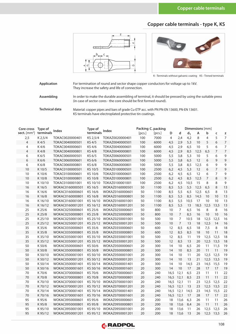
108
Copper cable terminals
z
b c
Core crosssect. [mm2]
Type ofterminals Index Type of
terminals IndexPacking C. packing
[pcs.]Dimensions [mm]
[pcs.] D d d1 A b c z2,5 K 2,5/4 TOKAC0020000401 KS 2,5/4 TOKAZ0020000401 100 7000 4 2,4 4,2 8 4 5 74 K 4/5 TOKAC0040000501 KS 4/5 TOKAZ0040000501 100 6000 4,5 2,9 5,3 10 5 6 74 K 4/6 TOKAC0040000601 KS 4/6 TOKAZ0040000601 100 6000 4,5 2,9 6,5 10 5 6 74 K 4/8 TOKAC0040000801 KS 4/8 TOKAZ0040000801 100 6000 4,5 2,9 8,5 12,5 6,5 7 76 K 6/5 TOKAC0060000501 KS 6/5 TOKAZ0060000501 100 5000 5,5 3,8 5,3 10 5 6 96 K 6/6 TOKAC0060000601 KS 6/6 TOKAZ0060000601 100 5000 5,5 3,8 6,5 12 6 9 96 K 6/8 TOKAC0060000801 KS 6/8 TOKAZ0060000801 100 5000 5,5 3,8 8,5 12,5 6 9 9
10 K 10/5 TOKAC0100000501 KS 10/5 TOKAZ0100000501 100 2500 6,2 4,5 5,3 12 6 7 910 K 10/6 TOKAC0100000601 KS 10/6 TOKAZ0100000601 100 2500 6,2 4,5 6,5 12 6 7 910 K 10/8 TOKAC0100000801 KS 10/8 TOKAZ0100000801 100 2500 6,2 4,5 8,5 12,5 7 8 910 K 10/10 TOKAC0100001001 KS 10/10 TOKAZ0100001001 100 2500 6,2 4,5 10,5 15 8 8 916 K 16/5 WOKAC0160000501 KS 16/5 WOKAZ0160000501 50 1100 8,5 5,5 5,5 12,5 6,5 8 1316 K 16/6 WOKAC0160000601 KS 16/6 WOKAZ0160000601 50 1100 8,5 5,5 6,5 12,5 6,5 8 1316 K 16/8 WOKAC0160000801 KS 16/8 WOKAZ0160000801 50 1100 8,5 5,5 8,5 14,5 10 10 1316 K 16/10 WOKAC0160001001 KS 16/10 WOKAZ0160001001 50 1100 8,5 5,5 10,5 17 10 10 1316 K 16/12 WOKAC0160001201 KS 16/12 WOKAZ0160001201 50 1100 8,5 5,5 13 18,5 12,5 13,5 1325 K 25/6 WOKAC0250000601 KS 25/6 WOKAZ0250000601 50 800 10 7 6,5 16 8 8 1625 K 25/8 WOKAC0250000801 KS 25/8 WOKAZ0250000801 50 800 10 7 8,5 16 10 10 1625 K 25/10 WOKAC0250001001 KS 25/10 WOKAZ0250001001 50 500 10 7 10.5 18 12,5 12,5 1625 K 25/12 WOKAC0250001201 KS 25/12 WOKAZ0250001201 50 500 10 7 13 18 12,5 14 1635 K 35/6 WOKAC0350000601 KS 35/6 WOKAZ0350000601 50 600 12 8,5 6,5 18 7,5 8 1835 K 35/8 WOKAC0350000801 KS 35/8 WOKAZ0350000801 50 600 12 8,5 8,5 18 10 11 1835 K 35/10 WOKAC0350001001 KS 35/10 WOKAZ0350001001 50 500 12 8,5 11 19 12,5 12,5 1835 K 35/12 WOKAC0350001201 KS 35/12 WOKAZ0350001201 50 500 12 8,5 13 20 12,5 13,5 1850 K 50/6 WOKAC0500000601 KS 50/6 WOKAZ0500000601 20 300 14 10 6,5 20 11 11,5 1950 K 50/8 WOKAC0500000801 KS 50/8 WOKAZ0500000801 20 300 14 10 8,5 20 11 11 1950 K 50/10 WOKAC0500001001 KS 50/10 WOKAZ0500001001 20 300 14 10 11 20 12,5 12,5 1950 K 50/12 WOKAC0500001201 KS 50/12 WOKAZ0500001201 20 300 14 10 13 21 12,5 13,5 1950 K 50/14 WOKAC0500001401 KS 50/14 WOKAZ0500001401 20 300 14 10 14,5 23 14,5 15,5 1950 K 50/16 WOKAC0500001601 KS 50/16 WOKAZ0500001601 20 300 14 10 17 28 17 17 1970 K 70/6 WOKAC0700000601 KS 70/6 WOKAZ0700000601 20 240 16,5 12,1 6,5 23 11 11 2270 K 70/8 WOKAC0700000801 KS 70/8 WOKAZ0700000801 20 240 16,5 12,1 8,5 23 11 11 2270 K 70/10 WOKAC0700001001 KS 70/10 WOKAZ0700001001 20 240 16,5 12,1 11 23 12,5 12,5 2270 K 70/12 WOKAC0700001201 KS 70/12 WOKAZ0700001201 20 240 16,5 12,1 13 23 12,5 13,5 2270 K 70/14 WOKAC0700001401 KS 70/14 WOKAZ0700001401 20 240 16,5 12,1 14,5 23 14,5 15,5 2270 K 70/16 WOKAC0700001601 KS 70/16 WOKAZ0700001601 20 240 16,5 12,1 17 28 17 17 2295 K 95/6 WOKAC0950000601 KS 95/6 WOKAZ0950000601 20 200 18 13,6 6,3 26 11 11 2695 K 95/8 WOKAC0950000801 KS 95/8 WOKAZ0950000801 20 200 18 13,6 8,4 26 11 11 2695 K 95/10 WOKAC0950001001 KS 95/10 WOKAZ0950001001 20 200 18 13,6 11 26 12,5 12,5 2695 K 95/12 WOKAC0950001201 KS 95/12 WOKAZ0950001201 20 200 18 13,6 13 26 12,5 13,5 26
K - Terminals without galvanic coating KS - Tinned terminals
Copper cable terminals - type K, KS
For termination of round and sector shape copper conductors for voltage up to 1kV.They increase the safety and life of connection.
In order to make the durable assembling of terminal, it should be pressed by using the suitable press(in case of sector cores - the core should be first formed round).
Material: copper pipes and bars of grade Cu-ETP acc. with PN PN-EN 13600, PN-EN 13601.KS terminals have electroplated protective tin coatings.
Application
Assembling
Technical data
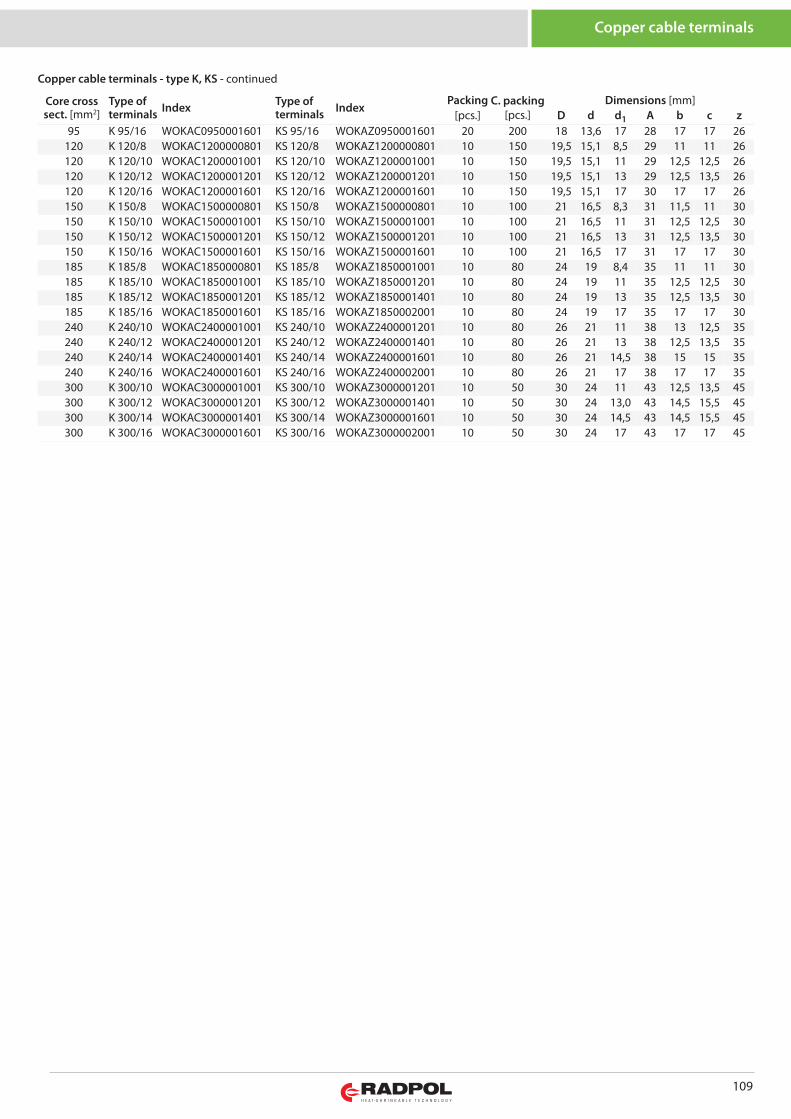
109
Copper cable terminals
Core crosssect. [mm2]
Type ofterminals Index Type of
terminals IndexPacking C. packing
[pcs.]Dimensions [mm]
[pcs.] D d d1 A b c z95 K 95/16 WOKAC0950001601 KS 95/16 WOKAZ0950001601 20 200 18 13,6 17 28 17 17 26
120 K 120/8 WOKAC1200000801 KS 120/8 WOKAZ1200000801 10 150 19,5 15,1 8,5 29 11 11 26120 K 120/10 WOKAC1200001001 KS 120/10 WOKAZ1200001001 10 150 19,5 15,1 11 29 12,5 12,5 26120 K 120/12 WOKAC1200001201 KS 120/12 WOKAZ1200001201 10 150 19,5 15,1 13 29 12,5 13,5 26120 K 120/16 WOKAC1200001601 KS 120/16 WOKAZ1200001601 10 150 19,5 15,1 17 30 17 17 26150 K 150/8 WOKAC1500000801 KS 150/8 WOKAZ1500000801 10 100 21 16,5 8,3 31 11,5 11 30150 K 150/10 WOKAC1500001001 KS 150/10 WOKAZ1500001001 10 100 21 16,5 11 31 12,5 12,5 30150 K 150/12 WOKAC1500001201 KS 150/12 WOKAZ1500001201 10 100 21 16,5 13 31 12,5 13,5 30150 K 150/16 WOKAC1500001601 KS 150/16 WOKAZ1500001601 10 100 21 16,5 17 31 17 17 30185 K 185/8 WOKAC1850000801 KS 185/8 WOKAZ1850001001 10 80 24 19 8,4 35 11 11 30185 K 185/10 WOKAC1850001001 KS 185/10 WOKAZ1850001201 10 80 24 19 11 35 12,5 12,5 30185 K 185/12 WOKAC1850001201 KS 185/12 WOKAZ1850001401 10 80 24 19 13 35 12,5 13,5 30185 K 185/16 WOKAC1850001601 KS 185/16 WOKAZ1850002001 10 80 24 19 17 35 17 17 30240 K 240/10 WOKAC2400001001 KS 240/10 WOKAZ2400001201 10 80 26 21 11 38 13 12,5 35240 K 240/12 WOKAC2400001201 KS 240/12 WOKAZ2400001401 10 80 26 21 13 38 12,5 13,5 35240 K 240/14 WOKAC2400001401 KS 240/14 WOKAZ2400001601 10 80 26 21 14,5 38 15 15 35240 K 240/16 WOKAC2400001601 KS 240/16 WOKAZ2400002001 10 80 26 21 17 38 17 17 35300 K 300/10 WOKAC3000001001 KS 300/10 WOKAZ3000001201 10 50 30 24 11 43 12,5 13,5 45300 K 300/12 WOKAC3000001201 KS 300/12 WOKAZ3000001401 10 50 30 24 13,0 43 14,5 15,5 45300 K 300/14 WOKAC3000001401 KS 300/14 WOKAZ3000001601 10 50 30 24 14,5 43 14,5 15,5 45300 K 300/16 WOKAC3000001601 KS 300/16 WOKAZ3000002001 10 50 30 24 17 43 17 17 45
Copper cable terminals - type K, KS - continued
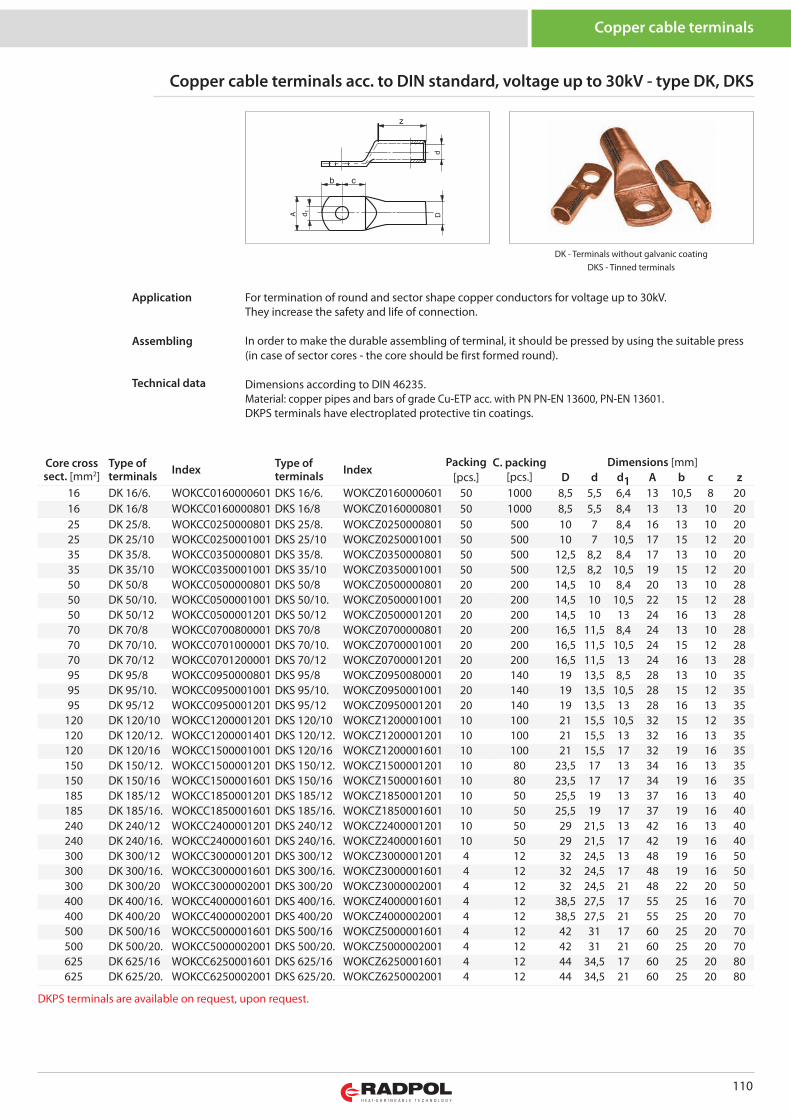
110
Core crosssect. [mm2]
Type ofterminals Index Type of
terminals IndexPacking C. packing
[pcs.]Dimensions [mm]
[pcs.] D d d1 A b c z16 DK 16/6. WOKCC0160000601 DKS 16/6. WOKCZ0160000601 50 1000 8,5 5,5 6,4 13 10,5 8 2016 DK 16/8 WOKCC0160000801 DKS 16/8 WOKCZ0160000801 50 1000 8,5 5,5 8,4 13 13 10 2025 DK 25/8. WOKCC0250000801 DKS 25/8. WOKCZ0250000801 50 500 10 7 8,4 16 13 10 2025 DK 25/10 WOKCC0250001001 DKS 25/10 WOKCZ0250001001 50 500 10 7 10,5 17 15 12 2035 DK 35/8. WOKCC0350000801 DKS 35/8. WOKCZ0350000801 50 500 12,5 8,2 8,4 17 13 10 2035 DK 35/10 WOKCC0350001001 DKS 35/10 WOKCZ0350001001 50 500 12,5 8,2 10,5 19 15 12 2050 DK 50/8 WOKCC0500000801 DKS 50/8 WOKCZ0500000801 20 200 14,5 10 8,4 20 13 10 2850 DK 50/10. WOKCC0500001001 DKS 50/10. WOKCZ0500001001 20 200 14,5 10 10,5 22 15 12 2850 DK 50/12 WOKCC0500001201 DKS 50/12 WOKCZ0500001201 20 200 14,5 10 13 24 16 13 2870 DK 70/8 WOKCC0700800001 DKS 70/8 WOKCZ0700000801 20 200 16,5 11,5 8,4 24 13 10 2870 DK 70/10. WOKCC0701000001 DKS 70/10. WOKCZ0700001001 20 200 16,5 11,5 10,5 24 15 12 2870 DK 70/12 WOKCC0701200001 DKS 70/12 WOKCZ0700001201 20 200 16,5 11,5 13 24 16 13 2895 DK 95/8 WOKCC0950000801 DKS 95/8 WOKCZ0950080001 20 140 19 13,5 8,5 28 13 10 3595 DK 95/10. WOKCC0950001001 DKS 95/10. WOKCZ0950001001 20 140 19 13,5 10,5 28 15 12 3595 DK 95/12 WOKCC0950001201 DKS 95/12 WOKCZ0950001201 20 140 19 13,5 13 28 16 13 35
120 DK 120/10 WOKCC1200001201 DKS 120/10 WOKCZ1200001001 10 100 21 15,5 10,5 32 15 12 35120 DK 120/12. WOKCC1200001401 DKS 120/12. WOKCZ1200001201 10 100 21 15,5 13 32 16 13 35120 DK 120/16 WOKCC1500001001 DKS 120/16 WOKCZ1200001601 10 100 21 15,5 17 32 19 16 35150 DK 150/12. WOKCC1500001201 DKS 150/12. WOKCZ1500001201 10 80 23,5 17 13 34 16 13 35150 DK 150/16 WOKCC1500001601 DKS 150/16 WOKCZ1500001601 10 80 23,5 17 17 34 19 16 35185 DK 185/12 WOKCC1850001201 DKS 185/12 WOKCZ1850001201 10 50 25,5 19 13 37 16 13 40185 DK 185/16. WOKCC1850001601 DKS 185/16. WOKCZ1850001601 10 50 25,5 19 17 37 19 16 40240 DK 240/12 WOKCC2400001201 DKS 240/12 WOKCZ2400001201 10 50 29 21,5 13 42 16 13 40240 DK 240/16. WOKCC2400001601 DKS 240/16. WOKCZ2400001601 10 50 29 21,5 17 42 19 16 40300 DK 300/12 WOKCC3000001201 DKS 300/12 WOKCZ3000001201 4 12 32 24,5 13 48 19 16 50300 DK 300/16. WOKCC3000001601 DKS 300/16. WOKCZ3000001601 4 12 32 24,5 17 48 19 16 50300 DK 300/20 WOKCC3000002001 DKS 300/20 WOKCZ3000002001 4 12 32 24,5 21 48 22 20 50400 DK 400/16. WOKCC4000001601 DKS 400/16. WOKCZ4000001601 4 12 38,5 27,5 17 55 25 16 70400 DK 400/20 WOKCC4000002001 DKS 400/20 WOKCZ4000002001 4 12 38,5 27,5 21 55 25 20 70500 DK 500/16 WOKCC5000001601 DKS 500/16 WOKCZ5000001601 4 12 42 31 17 60 25 20 70500 DK 500/20. WOKCC5000002001 DKS 500/20. WOKCZ5000002001 4 12 42 31 21 60 25 20 70625 DK 625/16 WOKCC6250001601 DKS 625/16 WOKCZ6250001601 4 12 44 34,5 17 60 25 20 80625 DK 625/20. WOKCC6250002001 DKS 625/20. WOKCZ6250002001 4 12 44 34,5 21 60 25 20 80
Copper cable terminals
Copper cable terminals acc. to DIN standard, voltage up to 30kV - type DK, DKS
DK - Terminals without galvanic coatingDKS - Tinned terminals
For termination of round and sector shape copper conductors for voltage up to 30kV.They increase the safety and life of connection.
In order to make the durable assembling of terminal, it should be pressed by using the suitable press(in case of sector cores - the core should be first formed round).
Dimensions according to DIN 46235.Material: copper pipes and bars of grade Cu-ETP acc. with PN PN-EN 13600, PN-EN 13601.DKPS terminals have electroplated protective tin coatings.
Application
Assembling
Technical data
DKPS terminals are available on request, upon request.
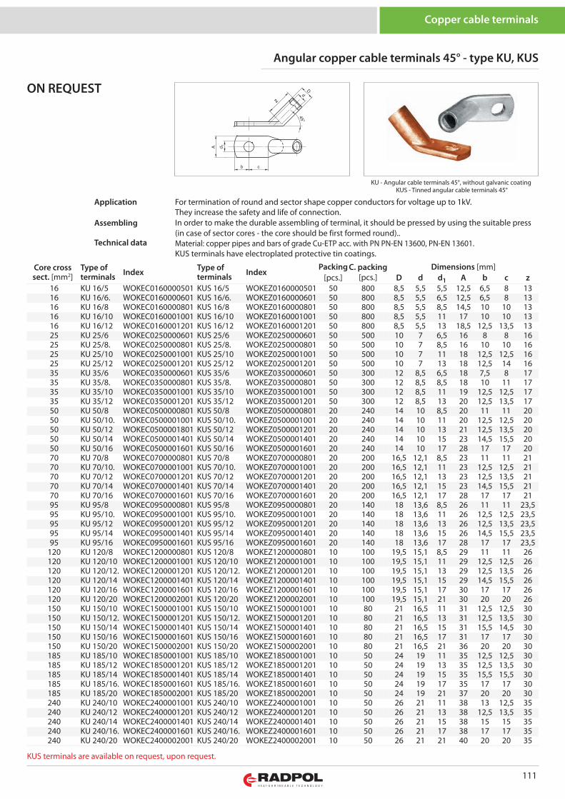
111
KU - Angular cable terminals 45°, without galvanic coatingKUS - Tinned angular cable terminals 45°
z
Angular copper cable terminals 45° - type KU, KUS
Copper cable terminals
For termination of round and sector shape copper conductors for voltage up to 1kV.They increase the safety and life of connection.In order to make the durable assembling of terminal, it should be pressed by using the suitable press(in case of sector cores - the core should be first formed round)..Material: copper pipes and bars of grade Cu-ETP acc. with PN PN-EN 13600, PN-EN 13601.KUS terminals have electroplated protective tin coatings.
Application
Assembling
Technical data
ON REQUEST
Core crosssect. [mm2]
Type ofterminals Index Type of
terminals IndexPacking C. packing
[pcs.]Dimensions [mm]
[pcs.] D d d1 A b c z16 KU 16/5 WOKEC0160000501 KUS 16/5 WOKEZ0160000501 50 800 8,5 5,5 5,5 12,5 6,5 8 1316 KU 16/6. WOKEC0160000601 KUS 16/6. WOKEZ0160000601 50 800 8,5 5,5 6,5 12,5 6,5 8 1316 KU 16/8 WOKEC0160000801 KUS 16/8 WOKEZ0160000801 50 800 8,5 5,5 8,5 14,5 10 10 1316 KU 16/10 WOKEC0160001001 KUS 16/10 WOKEZ0160001001 50 800 8,5 5,5 11 17 10 10 1316 KU 16/12 WOKEC0160001201 KUS 16/12 WOKEZ0160001201 50 800 8,5 5,5 13 18,5 12,5 13,5 1325 KU 25/6 WOKEC0250000601 KUS 25/6 WOKEZ0250000601 50 500 10 7 6,5 16 8 8 1625 KU 25/8. WOKEC0250000801 KUS 25/8. WOKEZ0250000801 50 500 10 7 8,5 16 10 10 1625 KU 25/10 WOKEC0250001001 KUS 25/10 WOKEZ0250001001 50 500 10 7 11 18 12,5 12,5 1625 KU 25/12 WOKEC0250001201 KUS 25/12 WOKEZ0250001201 50 500 10 7 13 18 12,5 14 1635 KU 35/6 WOKEC0350000601 KUS 35/6 WOKEZ0350000601 50 300 12 8,5 6,5 18 7,5 8 1735 KU 35/8. WOKEC0350000801 KUS 35/8. WOKEZ0350000801 50 300 12 8,5 8,5 18 10 11 1735 KU 35/10 WOKEC0350001001 KUS 35/10 WOKEZ0350001001 50 300 12 8,5 11 19 12,5 12,5 1735 KU 35/12 WOKEC0350001201 KUS 35/12 WOKEZ0350001201 50 300 12 8,5 13 20 12,5 13,5 1750 KU 50/8 WOKEC0500000801 KUS 50/8 WOKEZ0500000801 20 240 14 10 8,5 20 11 11 2050 KU 50/10. WOKEC0500001001 KUS 50/10. WOKEZ0500001001 20 240 14 10 11 20 12,5 12,5 2050 KU 50/12 WOKEC0500001801 KUS 50/12 WOKEZ0500001201 20 240 14 10 13 21 12,5 13,5 2050 KU 50/14 WOKEC0500001401 KUS 50/14 WOKEZ0500001401 20 240 14 10 15 23 14,5 15,5 2050 KU 50/16 WOKEC0500001601 KUS 50/16 WOKEZ0500001601 20 240 14 10 17 28 17 17 2070 KU 70/8 WOKEC0700000801 KUS 70/8 WOKEZ0700000801 20 200 16,5 12,1 8,5 23 11 11 2170 KU 70/10. WOKEC0700001001 KUS 70/10. WOKEZ0700001001 20 200 16,5 12,1 11 23 12,5 12,5 2170 KU 70/12 WOKEC0700001201 KUS 70/12 WOKEZ0700001201 20 200 16,5 12,1 13 23 12,5 13,5 2170 KU 70/14 WOKEC0700001401 KUS 70/14 WOKEZ0700001401 20 200 16,5 12,1 15 23 14,5 15,5 2170 KU 70/16 WOKEC0700001601 KUS 70/16 WOKEZ0700001601 20 200 16,5 12,1 17 28 17 17 2195 KU 95/8 WOKEC0950000801 KUS 95/8 WOKEZ0950000801 20 140 18 13,6 8,5 26 11 11 23,595 KU 95/10. WOKEC0950001001 KUS 95/10. WOKEZ0950001001 20 140 18 13,6 11 26 12,5 12,5 23,595 KU 95/12 WOKEC0950001201 KUS 95/12 WOKEZ0950001201 20 140 18 13,6 13 26 12,5 13,5 23,595 KU 95/14 WOKEC0950001401 KUS 95/14 WOKEZ0950001401 20 140 18 13,6 15 26 14,5 15,5 23,595 KU 95/16 WOKEC0950001601 KUS 95/16 WOKEZ0950001601 20 140 18 13,6 17 28 17 17 23,5
120 KU 120/8 WOKEC1200000801 KUS 120/8 WOKEZ1200000801 10 100 19,5 15,1 8,5 29 11 11 26120 KU 120/10 WOKEC1200001001 KUS 120/10 WOKEZ1200001001 10 100 19,5 15,1 11 29 12,5 12,5 26120 KU 120/12. WOKEC1200001201 KUS 120/12. WOKEZ1200001201 10 100 19,5 15,1 13 29 12,5 13,5 26120 KU 120/14 WOKEC1200001401 KUS 120/14 WOKEZ1200001401 10 100 19,5 15,1 15 29 14,5 15,5 26120 KU 120/16 WOKEC1200001601 KUS 120/16 WOKEZ1200001601 10 100 19,5 15,1 17 30 17 17 26120 KU 120/20 WOKEC1200002001 KUS 120/20 WOKEZ1200002001 10 100 19,5 15,1 21 30 20 20 26150 KU 150/10 WOKEC1500001001 KUS 150/10 WOKEZ1500001001 10 80 21 16,5 11 31 12,5 12,5 30150 KU 150/12. WOKEC1500001201 KUS 150/12. WOKEZ1500001201 10 80 21 16,5 13 31 12,5 13,5 30150 KU 150/14 WOKEC1500001401 KUS 150/14 WOKEZ1500001401 10 80 21 16,5 15 31 15,5 14,5 30150 KU 150/16 WOKEC1500001601 KUS 150/16 WOKEZ1500001601 10 80 21 16,5 17 31 17 17 30150 KU 150/20 WOKEC1500002001 KUS 150/20 WOKEZ1500002001 10 80 21 16,5 21 36 20 20 30185 KU 185/10 WOKEC1850001001 KUS 185/10 WOKEZ1850001001 10 50 24 19 11 35 12,5 12,5 30185 KU 185/12 WOKEC1850001201 KUS 185/12 WOKEZ1850001201 10 50 24 19 13 35 12,5 13,5 30185 KU 185/14 WOKEC1850001401 KUS 185/14 WOKEZ1850001401 10 50 24 19 15 35 15,5 15,5 30185 KU 185/16. WOKEC1850001601 KUS 185/16. WOKEZ1850001601 10 50 24 19 17 35 17 17 30185 KU 185/20 WOKEC1850002001 KUS 185/20 WOKEZ1850002001 10 50 24 19 21 37 20 20 30240 KU 240/10 WOKEC2400001001 KUS 240/10 WOKEZ2400001001 10 50 26 21 11 38 13 12,5 35240 KU 240/12 WOKEC2400001201 KUS 240/12 WOKEZ2400001201 10 50 26 21 13 38 12,5 13,5 35240 KU 240/14 WOKEC2400001401 KUS 240/14 WOKEZ2400001401 10 50 26 21 15 38 15 15 35240 KU 240/16. WOKEC2400001601 KUS 240/16. WOKEZ2400001601 10 50 26 21 17 38 17 17 35240 KU 240/20 WOKEC2400002001 KUS 240/20 WOKEZ2400002001 10 50 26 21 21 40 20 20 35
KUS terminals are available on request, upon request.
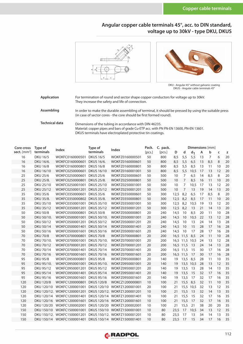
112
DKU - Angular 45° without galvanic coatingDKUS - Angular cable terminals 45°
z
Core crosssect. [mm2]
Type ofterminals Index Type of
terminals IndexPack. C. pack.
[pcs.]Dimensions [mm]
[pcs.] D d d1 A b c z16 DKU 16/5 WOKFC0160000501 DKUS 16/5 WOKFZ0160000501 50 800 8,5 5,5 5,5 13 7 6 2016 DKU 16/6. WOKFC0160000601 DKUS 16/6. WOKFZ0160000601 50 800 8,5 5,5 6,5 13 8,5 8 2016 DKU 16/8 WOKFC0160000801 DKUS 16/8 WOKFZ0160000801 50 800 8,5 5,5 8,5 13 11 10 2016 DKU 16/10 WOKFC0250000601 DKUS 16/10 WOKFZ0160001001 50 800 8,5 5,5 10,5 17 13 12 2025 DKU 25/6 WOKFC0250000601 DKUS 25/6 WOKFZ0250000601 50 500 10 7 6,5 14 8,5 8 2025 DKU 25/8. WOKFC0250000801 DKUS 25/8. WOKFZ0250000801 50 500 10 7 8,5 16 11 10 2025 DKU 25/10 WOKFC0250001001 DKUS 25/10 WOKFZ0250001001 50 500 10 7 10,5 17 13 12 2025 DKU 25/12 WOKFC0250001201 DKUS 25/12 WOKFZ0250001201 50 500 10 7 13 19 14 13 2035 DKU 35/6 WOKFC0350000601 DKUS 35/6 WOKFZ0350000601 50 300 12,5 8,2 6,5 17 8,5 8 2035 DKU 35/8. WOKFC0350000802 DKUS 35/8. WOKFZ0350000801 50 300 12,5 8,2 8,5 17 11 10 2035 DKU 35/10 WOKFC0350001001 DKUS 35/10 WOKFZ0350001001 50 300 12,5 8,2 10,5 19 13 12 2035 DKU 35/12 WOKFC0350001201 DKUS 35/12 WOKFZ0350001201 50 300 12,5 8,2 13 21 14 13 2050 DKU 50/8 WOKFC0500000801 DKUS 50/8 WOKFZ0500000801 20 240 14,5 10 8,5 20 11 10 2850 DKU 50/10. WOKFC0500001001 DKUS 50/10. WOKFZ0500001001 20 240 14,5 10 10,5 22 13 12 2850 DKU 50/12 WOKFC0500001201 DKUS 50/12 WOKFZ0500001201 20 240 14,5 10 13 24 14 13 2850 DKU 50/14 WOKFC0500001401 DKUS 50/14 WOKFZ0500001401 20 240 14,5 10 15 28 17 16 2850 DKU 50/16 WOKFC0500001601 DKUS 50/16 WOKFZ0500001601 20 240 14,5 10 17 28 17 16 2870 DKU 70/8 WOKFC0700000801 DKUS 70/8 WOKFZ0700000801 20 200 16,5 11,5 8,5 24 11 10 2870 DKU 70/10. WOKFC0700001001 DKUS 70/10. WOKFZ0700001001 20 200 16,5 11,5 10,5 24 13 12 2870 DKU 70/12 WOKFC0700001201 DKUS 70/12 WOKFZ0700001201 20 200 16,5 11,5 13 24 14 13 2870 DKU 70/14 WOKFC0700001401 DKUS 70/14 WOKFZ0700001401 20 200 16,5 11,5 15 30 17 16 2870 DKU 70/16 WOKFC0700001601 DKUS 70/16 WOKFZ0700001601 20 200 16,5 11,5 17 30 17 16 2895 DKU 95/8 WOKFC0950000801 DKUS 95/8 WOKFZ0950000801 20 140 19 13,5 8,5 28 11 10 3595 DKU 95/10. WOKFC0950001001 DKUS 95/10. WOKFZ0950001001 20 140 19 13,5 10,5 28 13 12 3595 DKU 95/12 WOKFC0950001201 DKUS 95/12 WOKFZ0950001201 20 140 19 13,5 13 28 14 13 3595 DKU 95/14 WOKFC0950001401 DKUS 95/14 WOKFZ0950001401 20 140 19 13,5 15 32 17 16 3595 DKU 95/16 WOKFC0950001601 DKUS 95/16 WOKFZ0950001601 20 140 19 13,5 17 32 17 16 35
120 DKU 120/8 WOKFC1200000801 DKUS 120/8 WOKCZ1200000801 10 100 21 15,5 8,5 32 11 10 35120 DKU 120/10 WOKFC1200001001 DKUS 120/10 WOKFZ1200001001 20 100 21 15,5 10,5 32 13 12 35120 DKU 120/12. WOKFC1200001201 DKUS 120/12. WOKFZ1200001201 10 100 21 15,5 13 32 14 13 35120 DKU 120/14 WOKFC1200001401 DKUS 120/14 WOKFZ1200001401 10 100 21 15,5 15 32 17 16 35120 DKU 120/16 WOKFC1200001601 DKUS 120/16 WOKFZ1200001601 10 100 21 15,5 17 32 17 16 35120 DKU 120/20 WOKFC1200002001 DKUS 120/20 WOKFZ1200002001 10 100 21 15,5 21 38 20 20 35150 DKU 150/10 WOKFC1500001001 DKUS 150/10 WOKFZ1500001001 10 80 23,5 17 10,5 34 13 12 35150 DKU 150/12. WOKFC1500001201 DKUS 150/12. WOKFZ1500001201 10 80 23,5 17 13 34 14 13 35150 DKU 150/14 WOKFC1500001401 DKUS 150/14 WOKFZ1500001401 10 80 23,5 17 15 34 17 16 35
Angular copper cable terminals 45°, acc. to DIN standard, voltage up to 30kV - type DKU, DKUS
Copper cable terminals
For termination of round and sector shape copper conductors for voltage up to 30kV.They increase the safety and life of connection.
In order to make the durable assembling of terminal, it should be pressed by using the suitable press(in case of sector cores - the core should be first formed round).
Dimensions of the tubing in accordance with DIN 46235.Material: copper pipes and bars of grade Cu-ETP acc. with PN PN-EN 13600, PN-EN 13601.DKUS terminals have electroplated protective tin coatings.
Application
Assembling
Technical data

113
Copper cable terminals
Core crosssect. [mm2]
Type ofterminals Index Type of
terminals IndexPack. C. pac.
[pcs.]Dimensions [mm]
[pcs.] D d d1 A b c z150 DKU 150/16 WOKFC1500001601 DKUS 150/16 WOKFZ1500001601 10 80 23,5 17 17 34 17 16 35150 DKU 150/20 WOKFC1500002001 DKUS 150/20 WOKFZ1500002001 10 80 23,5 17 21 40 20 20 35185 DKU 185/10 WOKFC1850001001 DKUS 185/10 WOKFZ1850001001 10 50 25,5 19 10,5 37 13 12 40185 DKU 185/12 WOKFC1850001201 DKUS 185/12 WOKFZ1850001201 10 50 25,5 19 13 37 14 13 40185 DKU 185/14 WOKFC1850001401 DKUS 185/14 WOKFZ1850001401 10 50 25,5 19 15 37 17 16 40185 DKU 185/16. WOKFC1850001601 DKUS 185/16. WOKFZ1850001601 10 50 25,5 19 17 37 17 16 40185 DKU 185/20 WOKFC1850002001 DKUS 185/20 WOKFZ1850002001 10 50 25,5 19 21 40 20 20 40240 DKU 240/10 WOKFC2400001001 DKUS 240/10 WOKFZ2400001001 10 50 29 21,5 10,5 42 14 13 40240 DKU 240/12 WOKFC2400001201 DKUS 240/12 WOKFZ2400001201 10 50 29 21,5 13 42 14 13 40240 DKU 240/14 WOKFC2400001401 DKUS 240/14 WOKFZ2400001401 10 50 29 21,5 15 42 17 16 40240 DKU 240/16. WOKFC2400001601 DKUS 240/16. WOKFZ2400001601 10 50 29 21,5 17 42 17 16 40240 DKU 240/20 WOKFC2400002001 DKUS 240/20 WOKFZ2400002001 10 50 29 21,5 21 45 20 20 40
Angular copper cable terminals 45°, acc. to DIN standard, voltage up to 30kV - type DKU, DKUS - continued
DKUS terminals are available on request, upon request.
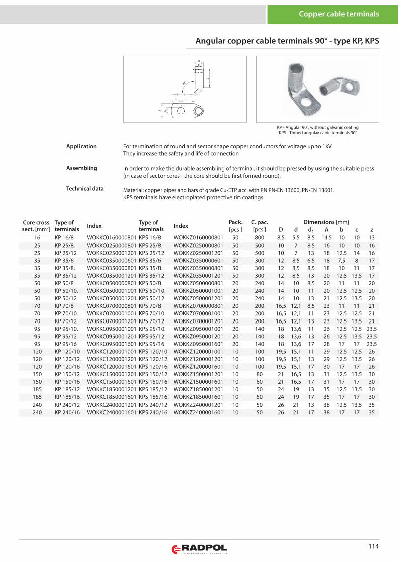
114
KP - Angular 90°, without galvanic coatingKPS - Tinned angular cable terminals 90°
Z
Core crosssect. [mm2]
Type ofterminals Index Type of
terminals IndexPack. C. pac.
[pcs.]Dimensions [mm]
[pcs.] D d d1 A b c z16 KP 16/8 WOKKC0160000801 KPS 16/8 WOKKZ0160000801 50 800 8,5 5,5 8,5 14,5 10 10 1325 KP 25/8. WOKKC0250000801 KPS 25/8. WOKKZ0250000801 50 500 10 7 8,5 16 10 10 1625 KP 25/12 WOKKC0250001201 KPS 25/12 WOKKZ0250001201 50 500 10 7 13 18 12,5 14 1635 KP 35/6 WOKKC0350000601 KPS 35/6 WOKKZ0350000601 50 300 12 8,5 6,5 18 7,5 8 1735 KP 35/8. WOKKC0350000801 KPS 35/8. WOKKZ0350000801 50 300 12 8,5 8,5 18 10 11 1735 KP 35/12 WOKKC0350001201 KPS 35/12 WOKKZ0350001201 50 300 12 8,5 13 20 12,5 13,5 1750 KP 50/8 WOKKC0500000801 KPS 50/8 WOKKZ0500000801 20 240 14 10 8,5 20 11 11 2050 KP 50/10. WOKKC0500001001 KPS 50/10. WOKKZ0500001001 20 240 14 10 11 20 12,5 12,5 2050 KP 50/12 WOKKC0500001201 KPS 50/12 WOKKZ0500001201 20 240 14 10 13 21 12,5 13,5 2070 KP 70/8 WOKKC0700000801 KPS 70/8 WOKKZ0700000801 20 200 16,5 12,1 8,5 23 11 11 2170 KP 70/10. WOKKC0700001001 KPS 70/10. WOKKZ0700001001 20 200 16,5 12,1 11 23 12,5 12,5 2170 KP 70/12 WOKKC0700001201 KPS 70/12 WOKKZ0700001201 20 200 16,5 12,1 13 23 12,5 13,5 2195 KP 95/10. WOKKC0950001001 KPS 95/10. WOKKZ0950001001 20 140 18 13,6 11 26 12,5 12,5 23,595 KP 95/12 WOKKC0950001201 KPS 95/12 WOKKZ0950001201 20 140 18 13,6 13 26 12,5 13,5 23,595 KP 95/16 WOKKC0950001601 KPS 95/16 WOKKZ0950001601 20 140 18 13,6 17 28 17 17 23,5
120 KP 120/10 WOKKC1200001001 KPS 120/10 WOKKZ1200001001 10 100 19,5 15,1 11 29 12,5 12,5 26120 KP 120/12. WOKKC1200001201 KPS 120/12. WOKKZ1200001201 10 100 19,5 15,1 13 29 12,5 13,5 26120 KP 120/16 WOKKC1200001601 KPS 120/16 WOKKZ1200001601 10 100 19,5 15,1 17 30 17 17 26150 KP 150/12. WOKKC1500001201 KPS 150/12. WOKKZ1500001201 10 80 21 16,5 13 31 12,5 13,5 30150 KP 150/16 WOKKC1500001601 KPS 150/16 WOKKZ1500001601 10 80 21 16,5 17 31 17 17 30185 KP 185/12 WOKKC1850001201 KPS 185/12 WOKKZ1850001201 10 50 24 19 13 35 12,5 13,5 30185 KP 185/16. WOKKC1850001601 KPS 185/16. WOKKZ1850001601 10 50 24 19 17 35 17 17 30240 KP 240/12 WOKKC2400001201 KPS 240/12 WOKKZ2400001201 10 50 26 21 13 38 12,5 13,5 35240 KP 240/16. WOKKC2400001601 KPS 240/16. WOKKZ2400001601 10 50 26 21 17 38 17 17 35
Angular copper cable terminals 90° - type KP, KPS
Copper cable terminals
For termination of round and sector shape copper conductors for voltage up to 1kV.They increase the safety and life of connection.
In order to make the durable assembling of terminal, it should be pressed by using the suitable press(in case of sector cores - the core should be first formed round).
Material: copper pipes and bars of grade Cu-ETP acc. with PN PN-EN 13600, PN-EN 13601.KPS terminals have electroplated protective tin coatings.
Application
Assembling
Technical data
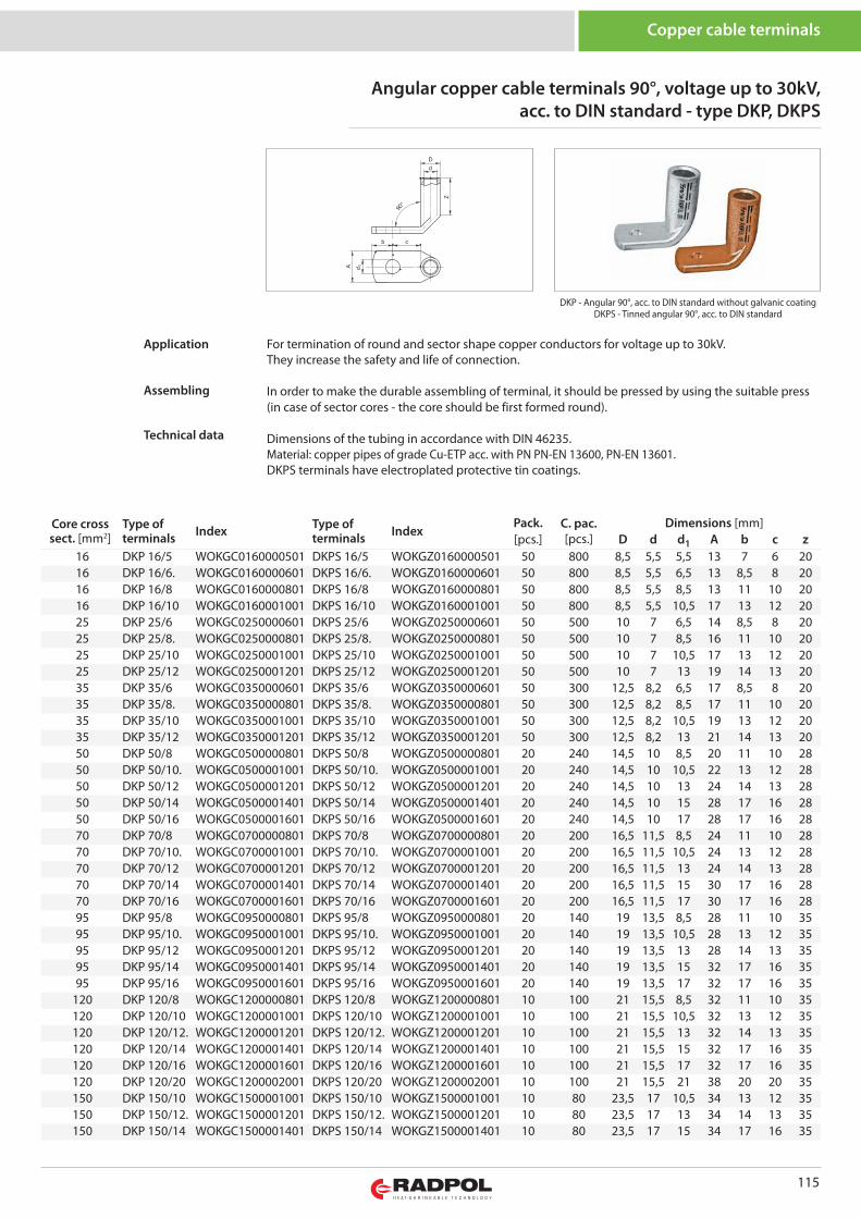
115
DKP - Angular 90°, acc. to DIN standard without galvanic coatingDKPS - Tinned angular 90°, acc. to DIN standard
Z
Core crosssect. [mm2]
Type ofterminals Index Type of
terminals IndexPack. C. pac.
[pcs.]Dimensions [mm]
[pcs.] D d d1 A b c z16 DKP 16/5 WOKGC0160000501 DKPS 16/5 WOKGZ0160000501 50 800 8,5 5,5 5,5 13 7 6 2016 DKP 16/6. WOKGC0160000601 DKPS 16/6. WOKGZ0160000601 50 800 8,5 5,5 6,5 13 8,5 8 2016 DKP 16/8 WOKGC0160000801 DKPS 16/8 WOKGZ0160000801 50 800 8,5 5,5 8,5 13 11 10 2016 DKP 16/10 WOKGC0160001001 DKPS 16/10 WOKGZ0160001001 50 800 8,5 5,5 10,5 17 13 12 2025 DKP 25/6 WOKGC0250000601 DKPS 25/6 WOKGZ0250000601 50 500 10 7 6,5 14 8,5 8 2025 DKP 25/8. WOKGC0250000801 DKPS 25/8. WOKGZ0250000801 50 500 10 7 8,5 16 11 10 2025 DKP 25/10 WOKGC0250001001 DKPS 25/10 WOKGZ0250001001 50 500 10 7 10,5 17 13 12 2025 DKP 25/12 WOKGC0250001201 DKPS 25/12 WOKGZ0250001201 50 500 10 7 13 19 14 13 2035 DKP 35/6 WOKGC0350000601 DKPS 35/6 WOKGZ0350000601 50 300 12,5 8,2 6,5 17 8,5 8 2035 DKP 35/8. WOKGC0350000801 DKPS 35/8. WOKGZ0350000801 50 300 12,5 8,2 8,5 17 11 10 2035 DKP 35/10 WOKGC0350001001 DKPS 35/10 WOKGZ0350001001 50 300 12,5 8,2 10,5 19 13 12 2035 DKP 35/12 WOKGC0350001201 DKPS 35/12 WOKGZ0350001201 50 300 12,5 8,2 13 21 14 13 2050 DKP 50/8 WOKGC0500000801 DKPS 50/8 WOKGZ0500000801 20 240 14,5 10 8,5 20 11 10 2850 DKP 50/10. WOKGC0500001001 DKPS 50/10. WOKGZ0500001001 20 240 14,5 10 10,5 22 13 12 2850 DKP 50/12 WOKGC0500001201 DKPS 50/12 WOKGZ0500001201 20 240 14,5 10 13 24 14 13 2850 DKP 50/14 WOKGC0500001401 DKPS 50/14 WOKGZ0500001401 20 240 14,5 10 15 28 17 16 2850 DKP 50/16 WOKGC0500001601 DKPS 50/16 WOKGZ0500001601 20 240 14,5 10 17 28 17 16 2870 DKP 70/8 WOKGC0700000801 DKPS 70/8 WOKGZ0700000801 20 200 16,5 11,5 8,5 24 11 10 2870 DKP 70/10. WOKGC0700001001 DKPS 70/10. WOKGZ0700001001 20 200 16,5 11,5 10,5 24 13 12 2870 DKP 70/12 WOKGC0700001201 DKPS 70/12 WOKGZ0700001201 20 200 16,5 11,5 13 24 14 13 2870 DKP 70/14 WOKGC0700001401 DKPS 70/14 WOKGZ0700001401 20 200 16,5 11,5 15 30 17 16 2870 DKP 70/16 WOKGC0700001601 DKPS 70/16 WOKGZ0700001601 20 200 16,5 11,5 17 30 17 16 2895 DKP 95/8 WOKGC0950000801 DKPS 95/8 WOKGZ0950000801 20 140 19 13,5 8,5 28 11 10 3595 DKP 95/10. WOKGC0950001001 DKPS 95/10. WOKGZ0950001001 20 140 19 13,5 10,5 28 13 12 3595 DKP 95/12 WOKGC0950001201 DKPS 95/12 WOKGZ0950001201 20 140 19 13,5 13 28 14 13 3595 DKP 95/14 WOKGC0950001401 DKPS 95/14 WOKGZ0950001401 20 140 19 13,5 15 32 17 16 3595 DKP 95/16 WOKGC0950001601 DKPS 95/16 WOKGZ0950001601 20 140 19 13,5 17 32 17 16 35
120 DKP 120/8 WOKGC1200000801 DKPS 120/8 WOKGZ1200000801 10 100 21 15,5 8,5 32 11 10 35120 DKP 120/10 WOKGC1200001001 DKPS 120/10 WOKGZ1200001001 10 100 21 15,5 10,5 32 13 12 35120 DKP 120/12. WOKGC1200001201 DKPS 120/12. WOKGZ1200001201 10 100 21 15,5 13 32 14 13 35120 DKP 120/14 WOKGC1200001401 DKPS 120/14 WOKGZ1200001401 10 100 21 15,5 15 32 17 16 35120 DKP 120/16 WOKGC1200001601 DKPS 120/16 WOKGZ1200001601 10 100 21 15,5 17 32 17 16 35120 DKP 120/20 WOKGC1200002001 DKPS 120/20 WOKGZ1200002001 10 100 21 15,5 21 38 20 20 35150 DKP 150/10 WOKGC1500001001 DKPS 150/10 WOKGZ1500001001 10 80 23,5 17 10,5 34 13 12 35150 DKP 150/12. WOKGC1500001201 DKPS 150/12. WOKGZ1500001201 10 80 23,5 17 13 34 14 13 35150 DKP 150/14 WOKGC1500001401 DKPS 150/14 WOKGZ1500001401 10 80 23,5 17 15 34 17 16 35
Angular copper cable terminals 90°, voltage up to 30kV, acc. to DIN standard - type DKP, DKPS
Copper cable terminals
For termination of round and sector shape copper conductors for voltage up to 30kV.They increase the safety and life of connection.
In order to make the durable assembling of terminal, it should be pressed by using the suitable press(in case of sector cores - the core should be first formed round).
Dimensions of the tubing in accordance with DIN 46235.Material: copper pipes of grade Cu-ETP acc. with PN PN-EN 13600, PN-EN 13601.DKPS terminals have electroplated protective tin coatings.
Application
Assembling
Technical data

116
Copper cable terminals
Core crosssect. [mm2]
Type ofterminals Index Type of
terminals IndexPack. C. pac.
[pcs.]Dimensions [mm]
[pcs.] D d d1 A b c z150 DKP 150/16 WOKGC1500001601 DKPS 150/16 WOKGZ1500001601 10 80 23,5 17 17 34 17 16 35150 DKP 150/20 WOKGC1500002001 DKPS 150/20 WOKGZ1500002001 10 80 23,5 17 21 40 20 20 35185 DKP 185/10 WOKGC1850001001 DKPS 185/10 WOKGZ1850001001 10 50 25,5 19 10,5 37 13 12 40185 DKP 185/12 WOKGC1850001201 DKPS 185/12 WOKGZ1850001201 10 50 25,5 19 13 37 14 13 40185 DKP 185/14 WOKGC1850001401 DKPS 185/14 WOKGZ1850001401 10 50 25,5 19 15 37 17 16 40185 DKP 185/16. WOKGC1850001601 DKPS 185/16. WOKGZ1850001601 10 50 25,5 19 17 37 17 16 40185 DKP 185/20 WOKGC1850002001 DKPS 185/20 WOKGZ1850002001 10 50 25,5 19 21 40 20 20 40240 DKP 240/10 WOKGC2400001001 DKPS 240/10 WOKGZ2400001001 10 50 29 21,5 10,5 42 14 13 40240 DKP 240/12 WOKGC2400001201 DKPS 240/12 WOKGZ2400001201 10 50 29 21,5 13 42 14 13 40240 DKP 240/14 WOKGC2400001401 DKPS 240/14 WOKGZ2400001401 10 50 29 21,5 15 42 17 16 40240 DKP 240/16. WOKGC2400001601 DKPS 240/16. WOKGZ2400001601 10 50 29 21,5 17 42 17 16 40240 DKP 240/20 WOKGC2400002001 DKPS 240/20 WOKGZ2400002001 10 50 29 21,5 21 45 20 20 40
Angular copper cable terminals 90°, voltage up to 30kV, acc. to DIN standard - type DKP, DKPS - continued
DKPS terminals are available on request, upon request.
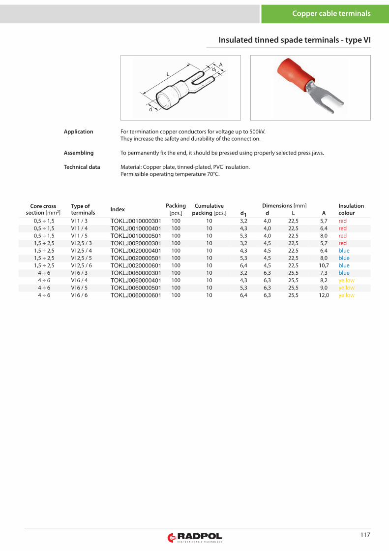
117
Copper cable terminals
Core crosssection [mm2]
Type ofterminals Index
Packing Cumulativepacking [pcs.]
Dimensions [mm] Insulationcolour[pcs.] d1 d L A
0,5 ÷ 1,5 VI 1 / 3 TOKLJ0010000301 100 10 3,2 4,0 22,5 5,7 red0,5 ÷ 1,5 VI 1 / 4 TOKLJ0010000401 100 10 4,3 4,0 22,5 6,4 red0,5 ÷ 1,5 VI 1 / 5 TOKLJ0010000501 100 10 5,3 4,0 22,5 8,0 red1,5 ÷ 2,5 VI 2,5 / 3 TOKLJ0020000301 100 10 3,2 4,5 22,5 5,7 red1,5 ÷ 2,5 VI 2,5 / 4 TOKLJ0020000401 100 10 4,3 4,5 22,5 6,4 blue1,5 ÷ 2,5 VI 2,5 / 5 TOKLJ0020000501 100 10 5,3 4,5 22,5 8,0 blue1,5 ÷ 2,5 VI 2,5 / 6 TOKLJ0020000601 100 10 6,4 4,5 22,5 10,7 blue
4 ÷ 6 VI 6 / 3 TOKLJ0060000301 100 10 3,2 6,3 25,5 7,3 blue4 ÷ 6 VI 6 / 4 TOKLJ0060000401 100 10 4,3 6,3 25,5 8,2 yellow4 ÷ 6 VI 6 / 5 TOKLJ0060000501 100 10 5,3 6,3 25,5 9,0 yellow4 ÷ 6 VI 6 / 6 TOKLJ0060000601 100 10 6,4 6,3 25,5 12,0 yellow
Insulated tinned spade terminals - type VI
For termination copper conductors for voltage up to 500kV.They increase the safety and durability of the connection.
To permanently fix the end, it should be pressed using properly selected press jaws.
Material: Copper plate, tinned-plated, PVC insulation.Permissible operating temperature 70°C.
Application
Assembling
Technical data
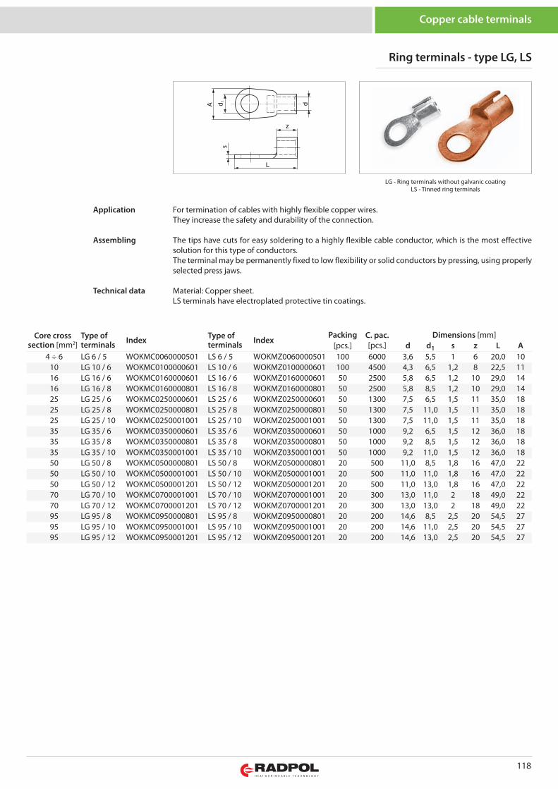
118
Copper cable terminals
LG - Ring terminals without galvanic coatingLS - Tinned ring terminals
z
s
Core crosssection [mm2]
Type ofterminals Index Type of
terminals IndexPacking C. pac.
[pcs.]Dimensions [mm]
[pcs.] d d1 s z L A4 ÷ 6 LG 6 / 5 WOKMC0060000501 LS 6 / 5 WOKMZ0060000501 100 6000 3,6 5,5 1 6 20,0 10
10 LG 10 / 6 WOKMC0100000601 LS 10 / 6 WOKMZ0100000601 100 4500 4,3 6,5 1,2 8 22,5 1116 LG 16 / 6 WOKMC0160000601 LS 16 / 6 WOKMZ0160000601 50 2500 5,8 6,5 1,2 10 29,0 1416 LG 16 / 8 WOKMC0160000801 LS 16 / 8 WOKMZ0160000801 50 2500 5,8 8,5 1,2 10 29,0 1425 LG 25 / 6 WOKMC0250000601 LS 25 / 6 WOKMZ0250000601 50 1300 7,5 6,5 1,5 11 35,0 1825 LG 25 / 8 WOKMC0250000801 LS 25 / 8 WOKMZ0250000801 50 1300 7,5 11,0 1,5 11 35,0 1825 LG 25 / 10 WOKMC0250001001 LS 25 / 10 WOKMZ0250001001 50 1300 7,5 11,0 1,5 11 35,0 1835 LG 35 / 6 WOKMC0350000601 LS 35 / 6 WOKMZ0350000601 50 1000 9,2 6,5 1,5 12 36,0 1835 LG 35 / 8 WOKMC0350000801 LS 35 / 8 WOKMZ0350000801 50 1000 9,2 8,5 1,5 12 36,0 1835 LG 35 / 10 WOKMC0350001001 LS 35 / 10 WOKMZ0350001001 50 1000 9,2 11,0 1,5 12 36,0 1850 LG 50 / 8 WOKMC0500000801 LS 50 / 8 WOKMZ0500000801 20 500 11,0 8,5 1,8 16 47,0 2250 LG 50 / 10 WOKMC0500001001 LS 50 / 10 WOKMZ0500001001 20 500 11,0 11,0 1,8 16 47,0 2250 LG 50 / 12 WOKMC0500001201 LS 50 / 12 WOKMZ0500001201 20 500 11,0 13,0 1,8 16 47,0 2270 LG 70 / 10 WOKMC0700001001 LS 70 / 10 WOKMZ0700001001 20 300 13,0 11,0 2 18 49,0 2270 LG 70 / 12 WOKMC0700001201 LS 70 / 12 WOKMZ0700001201 20 300 13,0 13,0 2 18 49,0 2295 LG 95 / 8 WOKMC0950000801 LS 95 / 8 WOKMZ0950000801 20 200 14,6 8,5 2,5 20 54,5 2795 LG 95 / 10 WOKMC0950001001 LS 95 / 10 WOKMZ0950001001 20 200 14,6 11,0 2,5 20 54,5 2795 LG 95 / 12 WOKMC0950001201 LS 95 / 12 WOKMZ0950001201 20 200 14,6 13,0 2,5 20 54,5 27
Ring terminals - type LG, LS
For termination of cables with highly flexible copper wires.They increase the safety and durability of the connection.
The tips have cuts for easy soldering to a highly flexible cable conductor, which is the most effectivesolution for this type of conductors.The terminal may be permanently fixed to low flexibility or solid conductors by pressing, using properlyselected press jaws.
Material: Copper sheet.LS terminals have electroplated protective tin coatings.
Application
Assembling
Technical data
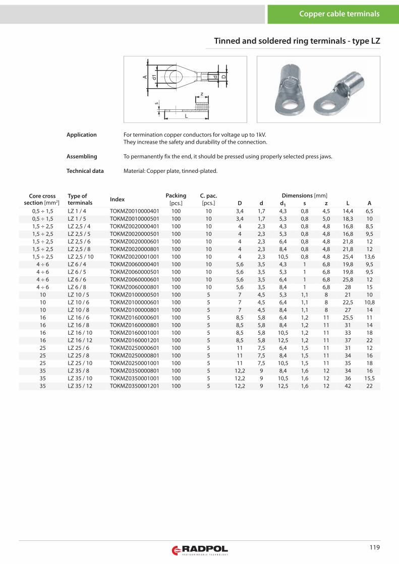
119
Core crosssection [mm2]
Type ofterminals Index
Packing C. pac. [pcs.]
Dimensions [mm][pcs.] D d d1 s z L A
0,5 ÷ 1,5 LZ 1 / 4 TOKMZ0010000401 100 10 3,4 1,7 4,3 0,8 4,5 14,4 6,50,5 ÷ 1,5 LZ 1 / 5 TOKMZ0010000501 100 10 3,4 1,7 5,3 0,8 5,0 18,3 101,5 ÷ 2,5 LZ 2,5 / 4 TOKMZ0020000401 100 10 4 2,3 4,3 0,8 4,8 16,8 8,51,5 ÷ 2,5 LZ 2,5 / 5 TOKMZ0020000501 100 10 4 2,3 5,3 0,8 4,8 16,8 9,51,5 ÷ 2,5 LZ 2,5 / 6 TOKMZ0020000601 100 10 4 2,3 6,4 0,8 4,8 21,8 121,5 ÷ 2,5 LZ 2,5 / 8 TOKMZ0020000801 100 10 4 2,3 8,4 0,8 4,8 21,8 121,5 ÷ 2,5 LZ 2,5 / 10 TOKMZ0020001001 100 10 4 2,3 10,5 0,8 4,8 25,4 13,6
4 ÷ 6 LZ 6 / 4 TOKMZ0060000401 100 10 5,6 3,5 4,3 1 6,8 19,8 9,54 ÷ 6 LZ 6 / 5 TOKMZ0060000501 100 10 5,6 3,5 5,3 1 6,8 19,8 9,54 ÷ 6 LZ 6 / 6 TOKMZ0060000601 100 10 5,6 3,5 6,4 1 6,8 25,8 124 ÷ 6 LZ 6 / 8 TOKMZ0060000801 100 10 5,6 3,5 8,4 1 6,8 28 15
10 LZ 10 / 5 TOKMZ0100000501 100 5 7 4,5 5,3 1,1 8 21 1010 LZ 10 / 6 TOKMZ0100000601 100 5 7 4,5 6,4 1,1 8 22,5 10,810 LZ 10 / 8 TOKMZ0100000801 100 5 7 4,5 8,4 1,1 8 27 1416 LZ 16 / 6 TOKMZ0160000601 100 5 8,5 5,8 6,4 1,2 11 25,5 1116 LZ 16 / 8 TOKMZ0160000801 100 5 8,5 5,8 8,4 1,2 11 31 1416 LZ 16 / 10 TOKMZ0160001001 100 5 8,5 5,8 10,5 1,2 11 33 1816 LZ 16 / 12 TOKMZ0160001201 100 5 8,5 5,8 12,5 1,2 11 37 2225 LZ 25 / 6 TOKMZ0250000601 100 5 11 7,5 6,4 1,5 11 31 1225 LZ 25 / 8 TOKMZ0250000801 100 5 11 7,5 8,4 1,5 11 34 1625 LZ 25 / 10 TOKMZ0250001001 100 5 11 7,5 10,5 1,5 11 35 1835 LZ 35 / 8 TOKMZ0350000801 100 5 12,2 9 8,4 1,6 12 34 1635 LZ 35 / 10 TOKMZ0350001001 100 5 12,2 9 10,5 1,6 12 36 15,535 LZ 35 / 12 TOKMZ0350001201 100 5 12,2 9 12,5 1,6 12 42 22
z
s
Tinned and soldered ring terminals - type LZ
Copper cable terminals
For termination copper conductors for voltage up to 1kV.They increase the safety and durability of the connection.
To permanently fix the end, it should be pressed using properly selected press jaws.
Material: Copper plate, tinned-plated.
Application
Assembling
Technical data
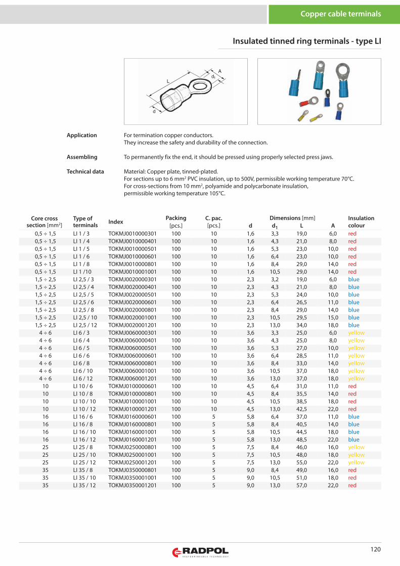
120
Core crosssection [mm2]
Type ofterminals Index
Packing C. pac. [pcs.]
Dimensions [mm] Insulationcolour[pcs.] d d1 L A
0,5 ÷ 1,5 LI 1 / 3 TOKMJ0010000301 100 10 1,6 3,3 19,0 6,0 red0,5 ÷ 1,5 LI 1 / 4 TOKMJ0010000401 100 10 1,6 4,3 21,0 8,0 red0,5 ÷ 1,5 LI 1 / 5 TOKMJ0010000501 100 10 1,6 5,3 23,0 10,0 red0,5 ÷ 1,5 LI 1 / 6 TOKMJ0010000601 100 10 1,6 6,4 23,0 10,0 red0,5 ÷ 1,5 LI 1 / 8 TOKMJ0010000801 100 10 1,6 8,4 29,0 14,0 red0,5 ÷ 1,5 LI 1 /10 TOKMJ0010001001 100 10 1,6 10,5 29,0 14,0 red1,5 ÷ 2,5 LI 2,5 / 3 TOKMJ0020000301 100 10 2,3 3,2 19,0 6,0 blue1,5 ÷ 2,5 LI 2,5 / 4 TOKMJ0020000401 100 10 2,3 4,3 21,0 8,0 blue1,5 ÷ 2,5 LI 2,5 / 5 TOKMJ0020000501 100 10 2,3 5,3 24,0 10,0 blue1,5 ÷ 2,5 LI 2,5 / 6 TOKMJ0020000601 100 10 2,3 6,4 26,5 11,0 blue1,5 ÷ 2,5 LI 2,5 / 8 TOKMJ0020000801 100 10 2,3 8,4 29,0 14,0 blue1,5 ÷ 2,5 LI 2,5 / 10 TOKMJ0020001001 100 10 2,3 10,5 29,5 15,0 blue1,5 ÷ 2,5 LI 2,5 / 12 TOKMJ0020001201 100 10 2,3 13,0 34,0 18,0 blue
4 ÷ 6 LI 6 / 3 TOKMJ0060000301 100 10 3,6 3,3 25,0 6,0 yellow4 ÷ 6 LI 6 / 4 TOKMJ0060000401 100 10 3,6 4,3 25,0 8,0 yellow4 ÷ 6 LI 6 / 5 TOKMJ0060000501 100 10 3,6 5,3 27,0 10,0 yellow4 ÷ 6 LI 6 / 6 TOKMJ0060000601 100 10 3,6 6,4 28,5 11,0 yellow4 ÷ 6 LI 6 / 8 TOKMJ0060000801 100 10 3,6 8,4 33,0 14,0 yellow4 ÷ 6 LI 6 / 10 TOKMJ0060001001 100 10 3,6 10,5 37,0 18,0 yellow4 ÷ 6 LI 6 / 12 TOKMJ0060001201 100 10 3,6 13,0 37,0 18,0 yellow
10 LI 10 / 6 TOKMJ0100000601 100 10 4,5 6,4 31,0 11,0 red10 LI 10 / 8 TOKMJ0100000801 100 10 4,5 8,4 35,5 14,0 red10 LI 10 / 10 TOKMJ0100001001 100 10 4,5 10,5 38,5 18,0 red10 LI 10 / 12 TOKMJ0100001201 100 10 4,5 13,0 42,5 22,0 red16 LI 16 / 6 TOKMJ0160000601 100 5 5,8 6,4 37,0 11,0 blue16 LI 16 / 8 TOKMJ0160000801 100 5 5,8 8,4 40,5 14,0 blue16 LI 16 / 10 TOKMJ0160001001 100 5 5,8 10,5 44,5 18,0 blue16 LI 16 / 12 TOKMJ0160001201 100 5 5,8 13,0 48,5 22,0 blue25 LI 25 / 8 TOKMJ0250000801 100 5 7,5 8,4 46,0 16,0 yellow25 LI 25 / 10 TOKMJ0250001001 100 5 7,5 10,5 48,0 18,0 yellow25 LI 25 / 12 TOKMJ0250001201 100 5 7,5 13,0 55,0 22,0 yellow35 LI 35 / 8 TOKMJ0350000801 100 5 9,0 8,4 49,0 16,0 red35 LI 35 / 10 TOKMJ0350001001 100 5 9,0 10,5 51,0 18,0 red35 LI 35 / 12 TOKMJ0350001201 100 5 9,0 13,0 57,0 22,0 red
Insulated tinned ring terminals - type LI
Copper cable terminals
For termination copper conductors.They increase the safety and durability of the connection.
To permanently fix the end, it should be pressed using properly selected press jaws.
Material: Copper plate, tinned-plated.For sections up to 6 mm2 PVC insulation, up to 500V, permissible working temperature 70°C.For cross-sections from 10 mm2, polyamide and polycarbonate insulation, permissible working temperature 105°C.
Application
Assembling
Technical data
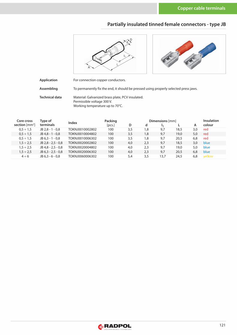
121
Partially insulated tinned female connectors - type JB
Copper cable terminals
For connection copper conductors.
To permanently fix the end, it should be pressed using properly selected press jaws.
Material: Galvanized brass plate, PCV insulated.Permissible voltage 300 V.Working temperature up to 70°C.
Application
Assembling
Technical data
Core crosssection [mm2]
Type ofterminals Index Packing Dimensions [mm] Insulation
colour[pcs.] D d l1 L A0,5 ÷ 1,5 JB 2,8 - 1 - 0,8 TOKNJ0010002802 100 3,5 1,8 9,7 18,5 3,0 red0,5 ÷ 1,5 JB 4,8 - 1 - 0,8 TOKNJ0010004802 100 3,5 1,8 9,7 19,0 5,0 red0,5 ÷ 1,5 JB 6,3 - 1 - 0,8 TOKNJ0010006302 100 3,5 1,8 9,7 20,5 6,8 red1,5 ÷ 2,5 JB 2,8 - 2,5 - 0,8 TOKNJ0020002802 100 4,0 2,3 9,7 18,5 3,0 blue1,5 ÷ 2,5 JB 4,8 - 2,5 - 0,8 TOKNJ0020004802 100 4,0 2,3 9,7 19,0 5,0 blue1,5 ÷ 2,5 JB 6,3 - 2,5 - 0,8 TOKNJ0020006302 100 4,0 2,3 9,7 20,5 6,8 blue
4 ÷ 6 JB 6,3 - 6 - 0,8 TOKNJ0060006302 100 5,4 3,5 13,7 24,5 6,8 yellow
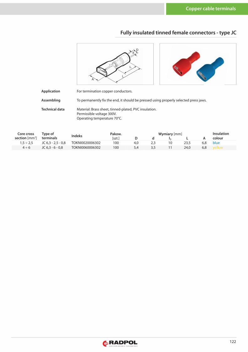
122
Copper cable terminals
Core crosssection [mm2]
Type ofterminals Indeks Pakow. Wymiary [mm] Insulation
colour[szt.] D d l1 L A1,5 ÷ 2,5 JC 6,3 - 2,5 - 0,8 TOKNI0020006302 100 4,0 2,3 10 23,5 6,8 blue
4 ÷ 6 JC 6,3 - 6 - 0,8 TOKNI0060006302 100 5,4 3,5 11 24,0 6,8 yellow
Fully insulated tinned female connectors - type JC
For termination copper conductors.
To permanently fix the end, it should be pressed using properly selected press jaws.
Material: Brass sheet, tinned-plated, PVC insulation.Permissible voltage 300V.Operating temperature 70°C.
Application
Assembling
Technical data
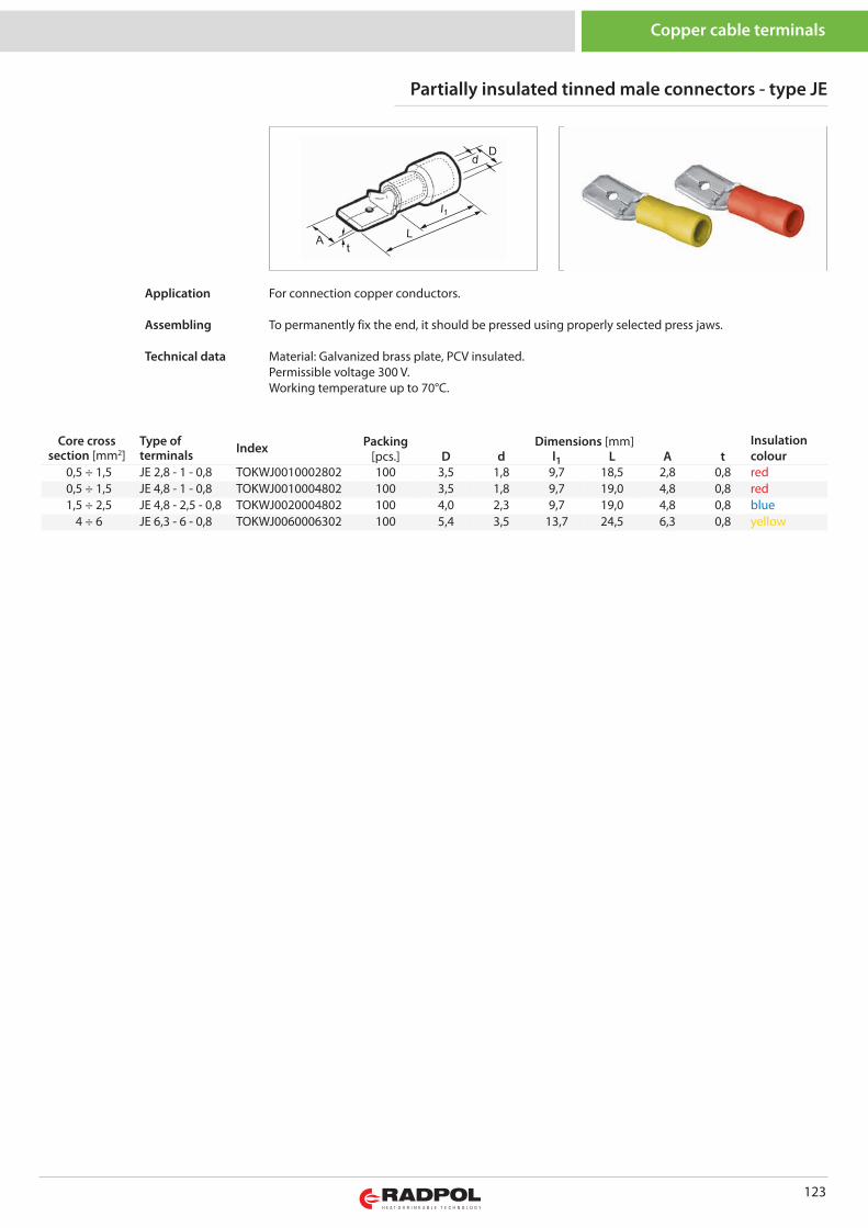
123
Copper cable terminals
Core crosssection [mm2]
Type ofterminals Index Packing Dimensions [mm] Insulation
colour[pcs.] D d l1 L A t0,5 ÷ 1,5 JE 2,8 - 1 - 0,8 TOKWJ0010002802 100 3,5 1,8 9,7 18,5 2,8 0,8 red0,5 ÷ 1,5 JE 4,8 - 1 - 0,8 TOKWJ0010004802 100 3,5 1,8 9,7 19,0 4,8 0,8 red1,5 ÷ 2,5 JE 4,8 - 2,5 - 0,8 TOKWJ0020004802 100 4,0 2,3 9,7 19,0 4,8 0,8 blue
4 ÷ 6 JE 6,3 - 6 - 0,8 TOKWJ0060006302 100 5,4 3,5 13,7 24,5 6,3 0,8 yellow
Partially insulated tinned male connectors - type JE
For connection copper conductors.
To permanently fix the end, it should be pressed using properly selected press jaws.
Material: Galvanized brass plate, PCV insulated.Permissible voltage 300 V.Working temperature up to 70°C.
Application
Assembling
Technical data
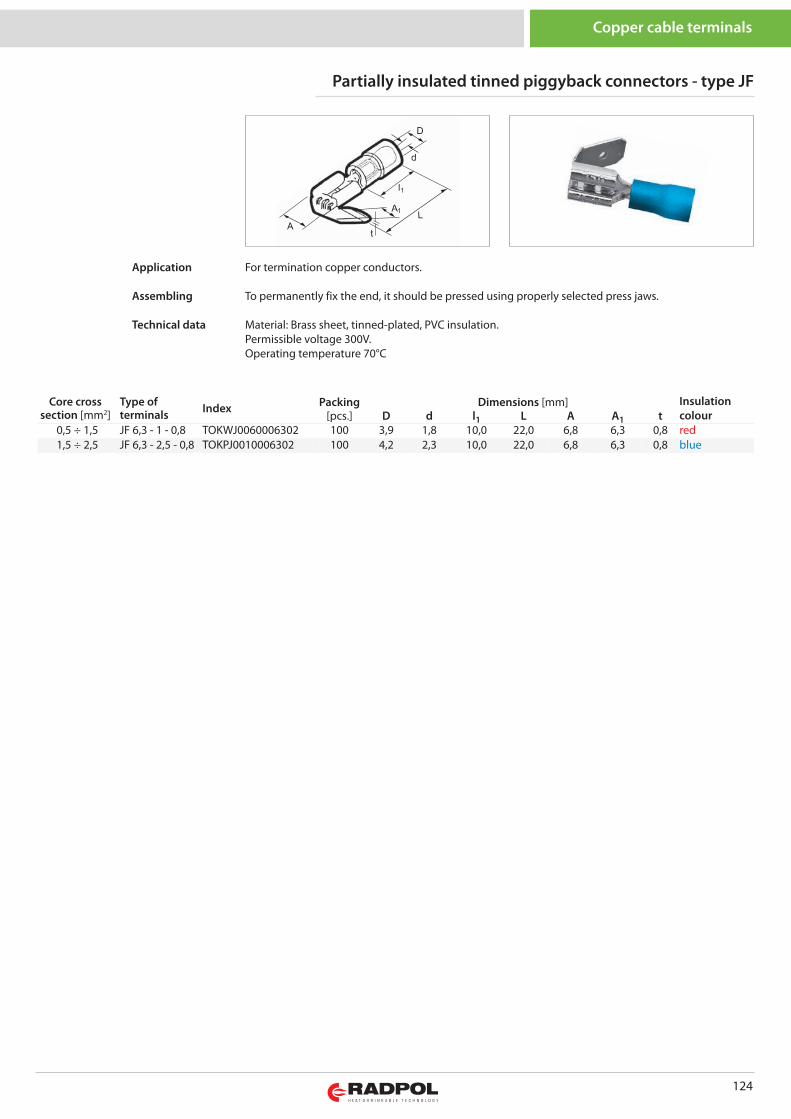
124
Copper cable terminals
Core crosssection [mm2]
Type ofterminals Index Packing Dimensions [mm] Insulation
colour [pcs.] D d l1 L A A1 t0,5 ÷ 1,5 JF 6,3 - 1 - 0,8 TOKWJ0060006302 100 3,9 1,8 10,0 22,0 6,8 6,3 0,8 red1,5 ÷ 2,5 JF 6,3 - 2,5 - 0,8 TOKPJ0010006302 100 4,2 2,3 10,0 22,0 6,8 6,3 0,8 blue
Partially insulated tinned piggyback connectors - type JF
For termination copper conductors.
To permanently fix the end, it should be pressed using properly selected press jaws.
Material: Brass sheet, tinned-plated, PVC insulation.Permissible voltage 300V.Operating temperature 70°C
Application
Assembling
Technical data
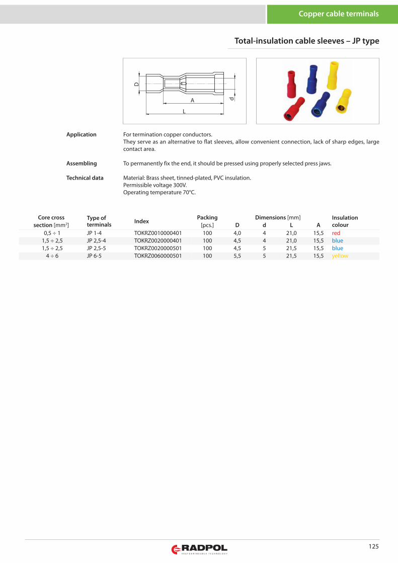
125
Copper cable terminals
Core cross Type ofterminals Index
Packing Dimensions [mm] Insulationcoloursection [mm2] [pcs.] D d L A
0,5 ÷ 1 JP 1-4 TOKRZ0010000401 100 4,0 4 21,0 15,5 red1,5 ÷ 2,5 JP 2,5-4 TOKRZ0020000401 100 4,5 4 21,0 15,5 blue1,5 ÷ 2,5 JP 2,5-5 TOKRZ0020000501 100 4,5 5 21,5 15,5 blue
4 ÷ 6 JP 6-5 TOKRZ0060000501 100 5,5 5 21,5 15,5 yellow
dA
L
D
Total-insulation cable sleeves – JP type
For termination copper conductors.They serve as an alternative to flat sleeves, allow convenient connection, lack of sharp edges, largecontact area.
To permanently fix the end, it should be pressed using properly selected press jaws.
Material: Brass sheet, tinned-plated, PVC insulation.Permissible voltage 300V.Operating temperature 70°C.
Application
Assembling
Technical data
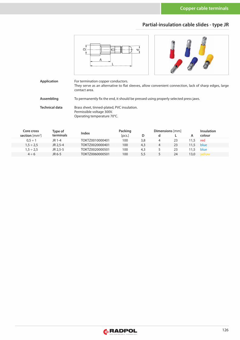
126
Copper cable terminals
Core cross Type ofterminals Index
Packing Dimensions [mm] Insulationcoloursection [mm2] [pcs.] D d L A
0,5 ÷ 1 JR 1-4 TOKTZ0010000401 100 3,8 4 23 11,5 red1,5 ÷ 2,5 JR 2,5-4 TOKTZ0020000401 100 4,3 4 23 11,5 blue1,5 ÷ 2,5 JR 2,5-5 TOKTZ0020000501 100 4,3 5 23 11,5 blue
4 ÷ 6 JR 6-5 TOKTZ0060000501 100 5,5 5 24 13,0 yellow
D
AL
d
Partial-insulation cable slides - type JR
For termination copper conductors. They serve as an alternative to flat sleeves, allow convenient connection, lack of sharp edges, largecontact area.
To permanently fix the end, it should be pressed using properly selected press jaws.
Brass sheet, tinned-plated, PVC insulation.Permissible voltage 300V.Operating temperature 70°C.
Application
Assembling
Technical data
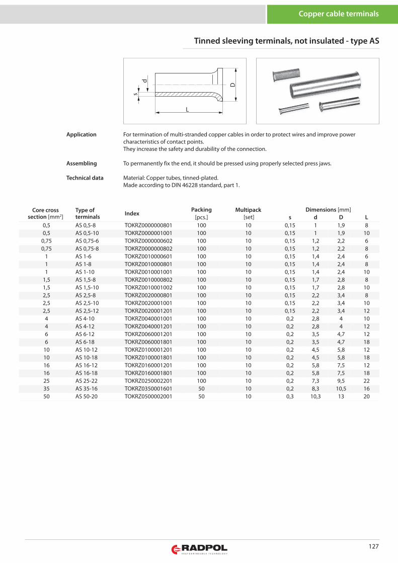
127
D
L
sd
Core crosssection [mm2]
Type ofterminals Index
Packing Multipack[set]
Dimensions [mm][pcs.] s d D L
0,5 AS 0,5-8 TOKRZ0000000801 100 10 0,15 1 1,9 80,5 AS 0,5-10 TOKRZ0000001001 100 10 0,15 1 1,9 10
0,75 AS 0,75-6 TOKRZ0000000602 100 10 0,15 1,2 2,2 60,75 AS 0,75-8 TOKRZ0000000802 100 10 0,15 1,2 2,2 8
1 AS 1-6 TOKRZ0010000601 100 10 0,15 1,4 2,4 61 AS 1-8 TOKRZ0010000801 100 10 0,15 1,4 2,4 81 AS 1-10 TOKRZ0010001001 100 10 0,15 1,4 2,4 10
1,5 AS 1,5-8 TOKRZ0010000802 100 10 0,15 1,7 2,8 81,5 AS 1,5-10 TOKRZ0010001002 100 10 0,15 1,7 2,8 102,5 AS 2,5-8 TOKRZ0020000801 100 10 0,15 2,2 3,4 82,5 AS 2,5-10 TOKRZ0020001001 100 10 0,15 2,2 3,4 102,5 AS 2,5-12 TOKRZ0020001201 100 10 0,15 2,2 3,4 124 AS 4-10 TOKRZ0040001001 100 10 0,2 2,8 4 104 AS 4-12 TOKRZ0040001201 100 10 0,2 2,8 4 126 AS 6-12 TOKRZ0060001201 100 10 0,2 3,5 4,7 126 AS 6-18 TOKRZ0060001801 100 10 0,2 3,5 4,7 18
10 AS 10-12 TOKRZ0100001201 100 10 0,2 4,5 5,8 1210 AS 10-18 TOKRZ0100001801 100 10 0,2 4,5 5,8 1816 AS 16-12 TOKRZ0160001201 100 10 0,2 5,8 7,5 1216 AS 16-18 TOKRZ0160001801 100 10 0,2 5,8 7,5 1825 AS 25-22 TOKRZ0250002201 100 10 0,2 7,3 9,5 2235 AS 35-16 TOKRZ0350001601 50 10 0,2 8,3 10,5 1650 AS 50-20 TOKRZ0500002001 50 10 0,3 10,3 13 20
Tinned sleeving terminals, not insulated - type AS
Copper cable terminals
For termination of multi-stranded copper cables in order to protect wires and improve powercharacteristics of contact points.They increase the safety and durability of the connection.
To permanently fix the end, it should be pressed using properly selected press jaws.
Material: Copper tubes, tinned-plated.Made according to DIN 46228 standard, part 1.
Application
Assembling
Technical data
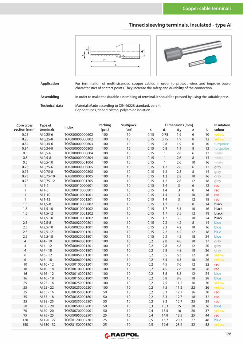
128
z
L
s
d 2
d 1
Core crosssection [mm2]
Type ofterminals Index
Packing Multipack[set]
Dimensions [mm] Insulationcolour[pcs.] s d1 d2 z L
0,25 AI 0,25-6 TOKRJ0000000602 100 10 0,15 0,75 1,9 6 10 yellow0,25 AI 0,25-8 TOKRJ0000000802 100 10 0,15 0,75 1,9 8 12 yellow0,34 AI 0,34-6 TOKRJ0000000603 100 10 0,15 0,8 1,9 6 10 turquoise0,34 AI 0,34-8 TOKRJ0000000803 100 10 0,15 0,8 1,9 8 12 turquoise0,5 AI 0,5-6 TOKRJ0000000604 100 10 0,15 1 2,6 6 12 white0,5 AI 0,5-8 TOKRJ0000000804 100 10 0,15 1 2,6 8 14 white0,5 AI 0,5-10 TOKRJ0000001004 100 10 0,15 1 2,6 10 16 white
0,75 AI 0,75-6 TOKRJ0000000605 100 10 0,15 1,2 2,8 6 12 gray0,75 AI 0,75-8 TOKRJ0000000805 100 10 0,15 1,2 2,8 8 14 gray0,75 AI 0,75-10 TOKRJ0000001005 100 10 0,15 1,2 2,8 10 16 gray0,75 AI 0,75-12 TOKRJ0000001205 100 10 0,15 1,2 2,8 12 18 gray
1 AI 1-6 TOKRJ0010000601 100 10 0,15 1,4 3 6 12 red1 AI 1-8 TOKRJ0010000801 100 10 0,15 1,4 3 8 14 red1 AI 1-10 TOKRJ0010001001 100 10 0,15 1,4 3 10 16 red1 AI 1-12 TOKRJ0010001201 100 10 0,15 1,4 3 12 18 red
1,5 AI 1,5-8 TOKRJ0010000802 100 10 0,15 1,7 3,5 8 14 black1,5 AI 1,5-10 TOKRJ0010001002 100 10 0,15 1,7 3,5 10 16 black1,5 AI 1,5-12 TOKRJ0010001202 100 10 0,15 1,7 3,5 12 18 black1,5 AI 1,5-18 TOKRJ0010001802 100 10 0,15 1,7 3,5 18 24 black2,5 AI 2,5-8 TOKRJ0020000801 100 10 0,15 2,2 4,2 8 14 blue2,5 AI 2,5-10 TOKRJ0020001001 100 10 0,15 2,2 4,2 10 16 blue2,5 AI 2,5-12 TOKRJ0020001201 100 10 0,15 2,2 4,2 12 18 blue2,5 AI 2,5-18 TOKRJ0020001801 100 10 0,15 2,2 4,2 18 24 blue4 AI 4 - 10 TOKRJ0040001001 100 10 0,2 2,8 4,8 10 17 gray4 AI 4 - 12 TOKRJ0040001201 100 10 0,2 2,8 4,8 12 20 gray4 AI 4 - 18 TOKRJ0040001801 100 10 0,2 2,8 4,8 18 26 gray6 AI 6 - 12 TOKRJ0060001201 100 10 0,2 3,5 6,3 12 20 yellow6 AI 6 - 18 TOKRJ0060001801 100 10 0,2 3,5 6,3 18 26 yellow
10 AI 10 - 12 TOKRJ0100001201 100 10 0,2 4,5 7,6 12 22 red10 AI 10 - 18 TOKRJ0100001801 100 10 0,2 4,5 7,6 18 28 red16 AI 16 - 12 TOKRJ0160001201 100 10 0,2 5,8 8,8 12 24 blue16 AI 16 - 18 TOKRJ0160001801 100 10 0,2 5,8 8,8 18 28 blue25 AI 25 - 16 TOKRJ0250001601 100 10 0,2 7,5 11,2 16 30 yellow25 AI 25 - 22 TOKRJ0250002201 100 10 0,2 7,5 11,2 22 36 yellow35 AI 35 - 16 TOKRJ0350001601 50 10 0,2 8,3 12,7 16 30 red35 AI 35 - 18 TOKRJ0350001801 50 10 0,2 8,3 12,7 18 32 red35 AI 35 - 25 TOKRJ0350002501 50 10 0,2 8,3 12,7 25 39 red50 AI 50 - 20 TOKRJ0500002001 50 10 0,3 10,3 15 20 36 blue70 AI 70 - 20 TOKRJ0700002001 50 10 0,4 13,5 16 20 37 yellow95 AI 95 - 25 TOKRJ0950002501 25 10 0,4 14,8 18,5 25 44 red
120 AI 120 - 27 TOKRJ1200002701 25 10 0,5 16,7 20,3 27 48 blue150 AI 150 - 32 TOKRJ1500003201 25 10 0,5 19,6 23,4 32 58 yellow
Tinned sleeving terminals, insulated - type AI
Copper cable terminals
For termination of multi-stranded copper cables in order to protect wires and improve powercharacteristics of contact points. They increase the safety and durability of the connection.
In order to make the durable assembling of terminal, it should be pressed by using the suitable press.
Material: Made according to DIN 46228 standard, part 4.Copper tubes, tinned-plated, polyamide isolation.
Application
Assembling
Technical data
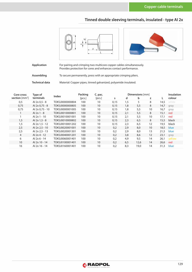
129
zL
sd
b
Core crosssection [mm2]
Type ofterminals Index
Packing C. pac. [pcs.]
Dimensions [mm] Insulationcolour[pcs.] s d b z L
0,5 AI 2x 0,5 - 8 TOKSJ0000000804 100 10 0,15 1,5 5 8 14,5 white0,75 AI 2x 0,75 - 8 TOKSJ0000000805 100 10 0,15 1,8 5,5 8 14,7 gray0,75 AI 2x 0,75 - 10 TOKSJ0000001005 100 10 0,15 1,8 5,5 10 16,7 gray
1 AI 2x 1 - 8 TOKSJ0010000801 100 10 0,15 2,1 5,5 8 15,1 red1 AI 2x 1 - 10 TOKSJ0010001001 100 10 0,15 2,1 5,5 10 17,1 red
1,5 AI 2x 1,5 - 8 TOKSJ0010000802 100 10 0,15 2,3 6,5 8 15,5 black1,5 AI 2x 1,5 - 12 TOKSJ0010001202 100 10 0,15 2,3 6,5 12 19,5 black2,5 AI 2x 2,5 - 10 TOKSJ0020001001 100 10 0,2 2,9 8,0 10 18,5 blue2,5 AI 2x 2,5 - 13 TOKSJ0020001301 100 10 0,2 2,9 8,0 13 21,5 blue4 AI 2x 4 - 12 TOKSJ0040001201 100 10 0,2 3,8 8,6 12 23,1 gray6 AI 2x 6 - 14 TOKSJ0060001401 100 10 0,2 4,9 9,5 14 26,1 yellow
10 AI 2x 10 - 14 TOKSJ0100001401 100 10 0,2 6,5 12,6 14 26,6 red16 AI 2x 16 - 14 TOKSJ0160001401 100 10 0,2 8,3 19,0 14 31,3 blue
Tinned double sleeving terminals, insulated - type AI 2x
Copper cable terminals
For pairing and crimping two multicore copper cables simultaneously.Provides protection for cores and enhances contact performance.
To secure permanently, press with an appropriate crimping pliers.
Material: Copper pipes, tinned galvanized, polyamide insulated.
Application
Assembling
Technical data
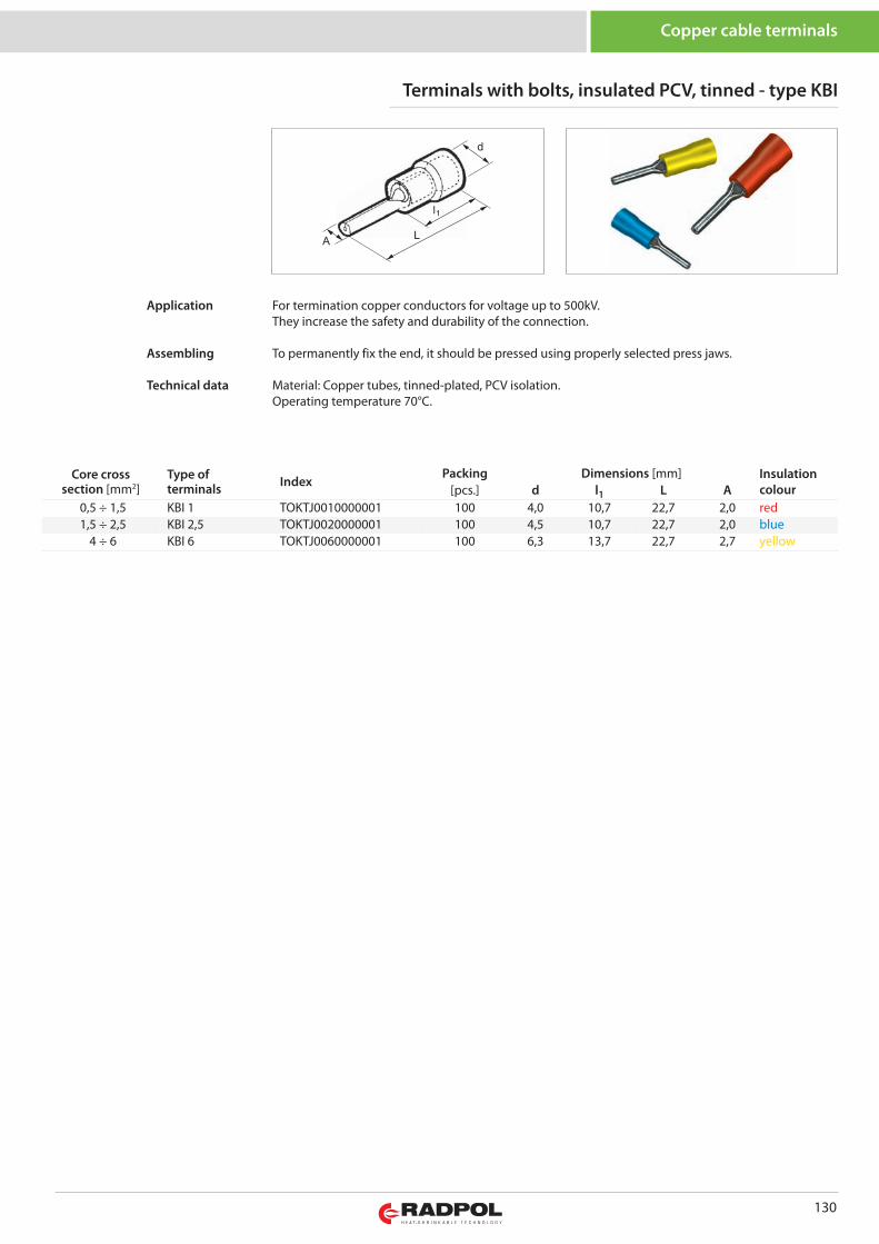
130
Copper cable terminals
Core crosssection [mm2]
Type ofterminals Index
Packing Dimensions [mm] Insulationcolour[pcs.] d l1 L A
0,5 ÷ 1,5 KBI 1 TOKTJ0010000001 100 4,0 10,7 22,7 2,0 red1,5 ÷ 2,5 KBI 2,5 TOKTJ0020000001 100 4,5 10,7 22,7 2,0 blue
4 ÷ 6 KBI 6 TOKTJ0060000001 100 6,3 13,7 22,7 2,7 yellow
Terminals with bolts, insulated PCV, tinned - type KBI
For termination copper conductors for voltage up to 500kV.They increase the safety and durability of the connection.
To permanently fix the end, it should be pressed using properly selected press jaws.
Material: Copper tubes, tinned-plated, PCV isolation.Operating temperature 70°C.
Application
Assembling
Technical data
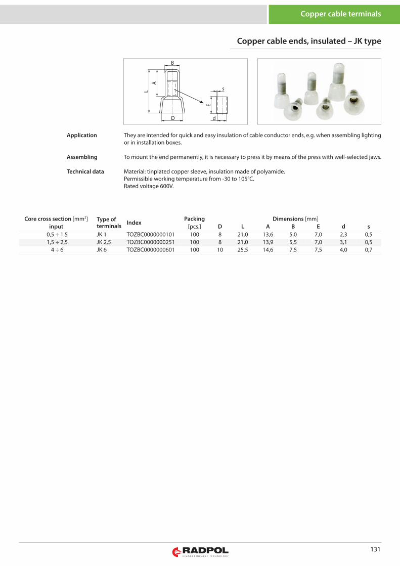
131
Copper cable terminals
Core cross section [mm2] Type ofterminals Index
Packing Dimensions [mm]input [pcs.] D L A B E d s
0,5 ÷ 1,5 JK 1 TOZBC0000000101 100 8 21,0 13,6 5,0 7,0 2,3 0,51,5 ÷ 2,5 JK 2,5 TOZBC0000000251 100 8 21,0 13,9 5,5 7,0 3,1 0,5
4 ÷ 6 JK 6 TOZBC0000000601 100 10 25,5 14,6 7,5 7,5 4,0 0,7
A
B
D d
E
sL
Copper cable ends, insulated – JK type
They are intended for quick and easy insulation of cable conductor ends, e.g. when assembling lightingor in installation boxes.
To mount the end permanently, it is necessary to press it by means of the press with well-selected jaws.
Material: tinplated copper sleeve, insulation made of polyamide.Permissible working temperature from -30 to 105°C.Rated voltage 600V.
Application
Assembling
Technical data
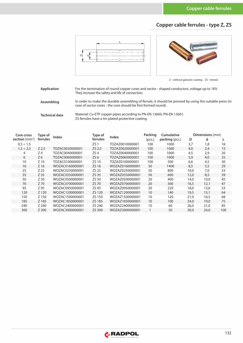
132
Core crosssection [mm2]
Type offerrules Index Type of
ferrules IndexPacking Cumulative
packing [pcs.]Dimensions [mm]
[pcs.] D d L0,5 ÷ 1,5 ZS 1 TOZAZ0010000001 100 1000 3,7 1,8 161,5 ÷ 2,5 Z 2,5 TOZAC0020000001 ZS 2,5 TOZAZ0020000001 100 1000 4,0 2,4 15
4 Z 4 TOZAC0040000001 ZS 4 TOZAZ0040000001 100 1000 4,5 2,9 206 Z 6 TOZAC0060000001 ZS 6 TOZAZ0060000001 100 1000 5,9 4,0 25
10 Z 10 TOZAC0100000001 ZS 10 TOZAZ0100000001 100 500 6,6 4,5 3016 Z 16 WOZAC0160000001 ZS 16 WOZAZ0160000001 50 1400 8,5 5,5 2925 Z 25 WOZAC0250000001 ZS 25 WOZAZ0250000001 50 800 10,0 7,0 3335 Z 35 WOZAC0350000001 ZS 35 WOZAZ0350000001 50 600 12,0 8,5 3950 Z 50 WOZAC0500000001 ZS 50 WOZAZ0500000001 20 400 14,0 10,0 4570 Z 70 WOZAC0700000001 ZS 70 WOZAZ0700000001 20 300 16,5 12,1 4795 Z 95 WOZAC0950000001 ZS 95 WOZAZ0950000001 20 220 18,0 13,6 53
120 Z 120 WOZAC1200000001 ZS 120 WOZAZ1200000001 10 140 19,5 15,1 64150 Z 150 WOZAC1500000001 ZS 150 WOZAZ1500000001 10 120 21,0 16,5 68185 Z 185 WOZAC1850000001 ZS 185 WOZAZ1850000001 10 100 24,0 19,0 75240 Z 240 WOZAC2400000001 ZS 240 WOZAZ2400000001 10 60 26,0 21,0 85300 Z 300 WOZAC3000000001 ZS 300 WOZAZ3000000001 1 50 30,0 24,0 100
Z - without galvanic coating ZS - tinned
Copper cable ferrules - type Z, ZS
Copper cable ferrules
For the termination of round copper cores and sector - shaped conductors, voltage up to 1KV.They increase the safety and life of connection.
In order to make the durable assembling of ferrule, it should be pressed by using the suitable press (incase of sector cores - the core should be first formed round).
Material: Cu-ETP copper pipes according to PN-EN 13600, PN-EN 13601.ZS ferrules have a tin-plated protective coating.
Application
Assembling
Technical data
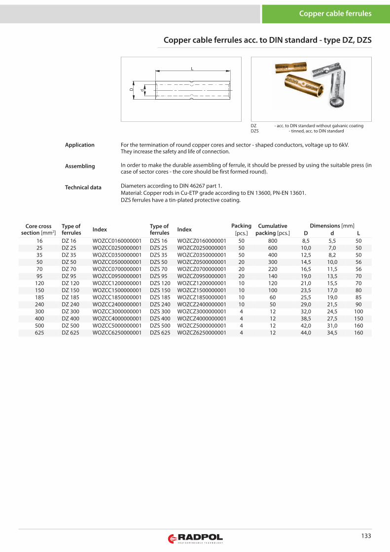
133
Core crosssection [mm2]
Type offerrules Index Type of
ferrules IndexPacking Cumulative
packing [pcs.]Dimensions [mm]
[pcs.] D d L16 DZ 16 WOZCC0160000001 DZS 16 WOZCZ0160000001 50 800 8,5 5,5 5025 DZ 25 WOZCC0250000001 DZS 25 WOZCZ0250000001 50 600 10,0 7,0 5035 DZ 35 WOZCC0350000001 DZS 35 WOZCZ0350000001 50 400 12,5 8,2 5050 DZ 50 WOZCC0500000001 DZS 50 WOZCZ0500000001 20 300 14,5 10,0 5670 DZ 70 WOZCC0700000001 DZS 70 WOZCZ0700000001 20 220 16,5 11,5 5695 DZ 95 WOZCC0950000001 DZS 95 WOZCZ0950000001 20 140 19,0 13,5 70
120 DZ 120 WOZCC1200000001 DZS 120 WOZCZ1200000001 10 120 21,0 15,5 70150 DZ 150 WOZCC1500000001 DZS 150 WOZCZ1500000001 10 100 23,5 17,0 80185 DZ 185 WOZCC1850000001 DZS 185 WOZCZ1850000001 10 60 25,5 19,0 85240 DZ 240 WOZCC2400000001 DZS 240 WOZCZ2400000001 10 50 29,0 21,5 90300 DZ 300 WOZCC3000000001 DZS 300 WOZCZ3000000001 4 12 32,0 24,5 100400 DZ 400 WOZCC4000000001 DZS 400 WOZCZ4000000001 4 12 38,5 27,5 150500 DZ 500 WOZCC5000000001 DZS 500 WOZCZ5000000001 4 12 42,0 31,0 160625 DZ 625 WOZCC6250000001 DZS 625 WOZCZ6250000001 4 12 44,0 34,5 160
Copper cable ferrules acc. to DIN standard - type DZ, DZS
Copper cable ferrules
For the termination of round copper cores and sector - shaped conductors, voltage up to 6kV. They increase the safety and life of connection.
In order to make the durable assembling of ferrule, it should be pressed by using the suitable press (incase of sector cores - the core should be first formed round).
Diameters according to DIN 46267 part 1.Material: Copper rods in Cu-ETP grade according to EN 13600, PN-EN 13601.DZS ferrules have a tin-plated protective coating.
Application
Assembling
Technical data
DZ - acc. to DIN standard without galvanic coatingDZS - tinned, acc. to DIN standard
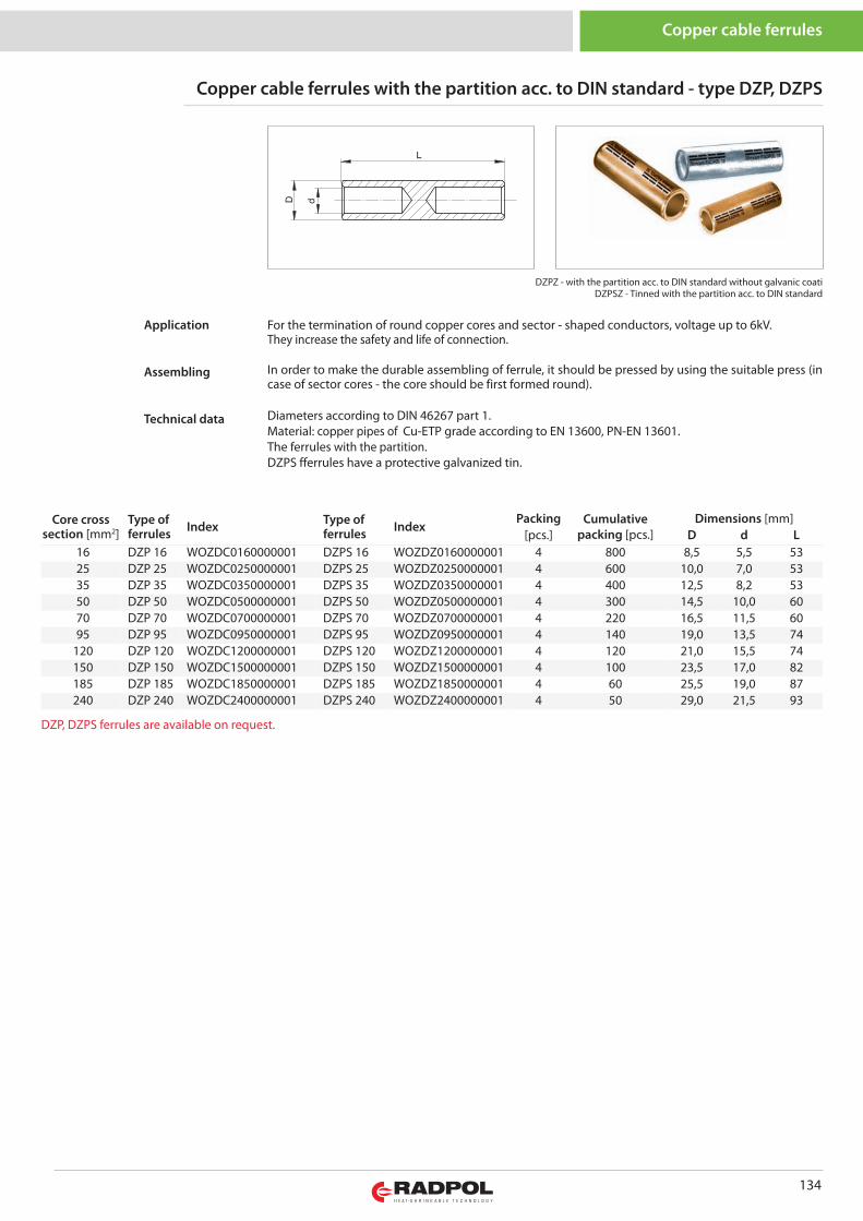
Core crosssection [mm2]
Type offerrules Index Type of
ferrules IndexPacking Cumulative
packing [pcs.]Dimensions [mm]
[pcs.] D d L16 DZP 16 WOZDC0160000001 DZPS 16 WOZDZ0160000001 4 800 8,5 5,5 5325 DZP 25 WOZDC0250000001 DZPS 25 WOZDZ0250000001 4 600 10,0 7,0 5335 DZP 35 WOZDC0350000001 DZPS 35 WOZDZ0350000001 4 400 12,5 8,2 5350 DZP 50 WOZDC0500000001 DZPS 50 WOZDZ0500000001 4 300 14,5 10,0 6070 DZP 70 WOZDC0700000001 DZPS 70 WOZDZ0700000001 4 220 16,5 11,5 6095 DZP 95 WOZDC0950000001 DZPS 95 WOZDZ0950000001 4 140 19,0 13,5 74
120 DZP 120 WOZDC1200000001 DZPS 120 WOZDZ1200000001 4 120 21,0 15,5 74150 DZP 150 WOZDC1500000001 DZPS 150 WOZDZ1500000001 4 100 23,5 17,0 82185 DZP 185 WOZDC1850000001 DZPS 185 WOZDZ1850000001 4 60 25,5 19,0 87240 DZP 240 WOZDC2400000001 DZPS 240 WOZDZ2400000001 4 50 29,0 21,5 93
DZPZ - with the partition acc. to DIN standard without galvanic coatiDZPSZ - Tinned with the partition acc. to DIN standard
Copper cable ferrules with the partition acc. to DIN standard - type DZP, DZPS
Copper cable ferrules
134
For the termination of round copper cores and sector - shaped conductors, voltage up to 6kV. They increase the safety and life of connection.
In order to make the durable assembling of ferrule, it should be pressed by using the suitable press (incase of sector cores - the core should be first formed round).
Diameters according to DIN 46267 part 1.Material: copper pipes of Cu-ETP grade according to EN 13600, PN-EN 13601.The ferrules with the partition.DZPS fferrules have a protective galvanized tin.
Application
Assembling
Technical data
DZP, DZPS ferrules are available on request.
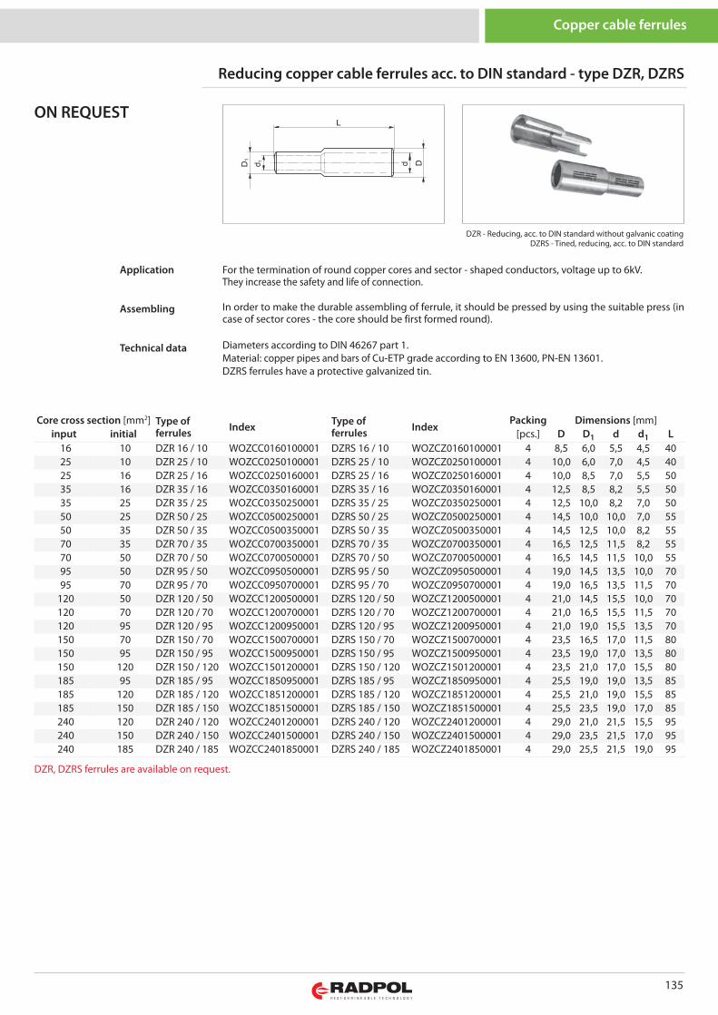
DZR - Reducing, acc. to DIN standard without galvanic coatingDZRS - Tined, reducing, acc. to DIN standard
Reducing copper cable ferrules acc. to DIN standard - type DZR, DZRS
Copper cable ferrules
135
For the termination of round copper cores and sector - shaped conductors, voltage up to 6kV. They increase the safety and life of connection.
In order to make the durable assembling of ferrule, it should be pressed by using the suitable press (incase of sector cores - the core should be first formed round).
Diameters according to DIN 46267 part 1.Material: copper pipes and bars of Cu-ETP grade according to EN 13600, PN-EN 13601.DZRS ferrules have a protective galvanized tin.
Application
Assembling
Technical data
ON REQUEST
Core cross section [mm2] Type offerrules Index Type of
ferrules IndexPacking Dimensions [mm]
input initial [pcs.] D D1 d d1 L16 10 DZR 16 / 10 WOZCC0160100001 DZRS 16 / 10 WOZCZ0160100001 4 8,5 6,0 5,5 4,5 4025 10 DZR 25 / 10 WOZCC0250100001 DZRS 25 / 10 WOZCZ0250100001 4 10,0 6,0 7,0 4,5 4025 16 DZR 25 / 16 WOZCC0250160001 DZRS 25 / 16 WOZCZ0250160001 4 10,0 8,5 7,0 5,5 5035 16 DZR 35 / 16 WOZCC0350160001 DZRS 35 / 16 WOZCZ0350160001 4 12,5 8,5 8,2 5,5 5035 25 DZR 35 / 25 WOZCC0350250001 DZRS 35 / 25 WOZCZ0350250001 4 12,5 10,0 8,2 7,0 5050 25 DZR 50 / 25 WOZCC0500250001 DZRS 50 / 25 WOZCZ0500250001 4 14,5 10,0 10,0 7,0 5550 35 DZR 50 / 35 WOZCC0500350001 DZRS 50 / 35 WOZCZ0500350001 4 14,5 12,5 10,0 8,2 5570 35 DZR 70 / 35 WOZCC0700350001 DZRS 70 / 35 WOZCZ0700350001 4 16,5 12,5 11,5 8,2 5570 50 DZR 70 / 50 WOZCC0700500001 DZRS 70 / 50 WOZCZ0700500001 4 16,5 14,5 11,5 10,0 5595 50 DZR 95 / 50 WOZCC0950500001 DZRS 95 / 50 WOZCZ0950500001 4 19,0 14,5 13,5 10,0 7095 70 DZR 95 / 70 WOZCC0950700001 DZRS 95 / 70 WOZCZ0950700001 4 19,0 16,5 13,5 11,5 70
120 50 DZR 120 / 50 WOZCC1200500001 DZRS 120 / 50 WOZCZ1200500001 4 21,0 14,5 15,5 10,0 70120 70 DZR 120 / 70 WOZCC1200700001 DZRS 120 / 70 WOZCZ1200700001 4 21,0 16,5 15,5 11,5 70120 95 DZR 120 / 95 WOZCC1200950001 DZRS 120 / 95 WOZCZ1200950001 4 21,0 19,0 15,5 13,5 70150 70 DZR 150 / 70 WOZCC1500700001 DZRS 150 / 70 WOZCZ1500700001 4 23,5 16,5 17,0 11,5 80150 95 DZR 150 / 95 WOZCC1500950001 DZRS 150 / 95 WOZCZ1500950001 4 23,5 19,0 17,0 13,5 80150 120 DZR 150 / 120 WOZCC1501200001 DZRS 150 / 120 WOZCZ1501200001 4 23,5 21,0 17,0 15,5 80185 95 DZR 185 / 95 WOZCC1850950001 DZRS 185 / 95 WOZCZ1850950001 4 25,5 19,0 19,0 13,5 85185 120 DZR 185 / 120 WOZCC1851200001 DZRS 185 / 120 WOZCZ1851200001 4 25,5 21,0 19,0 15,5 85185 150 DZR 185 / 150 WOZCC1851500001 DZRS 185 / 150 WOZCZ1851500001 4 25,5 23,5 19,0 17,0 85240 120 DZR 240 / 120 WOZCC2401200001 DZRS 240 / 120 WOZCZ2401200001 4 29,0 21,0 21,5 15,5 95240 150 DZR 240 / 150 WOZCC2401500001 DZRS 240 / 150 WOZCZ2401500001 4 29,0 23,5 21,5 17,0 95240 185 DZR 240 / 185 WOZCC2401850001 DZRS 240 / 185 WOZCZ2401850001 4 29,0 25,5 21,5 19,0 95
DZR, DZRS ferrules are available on request.
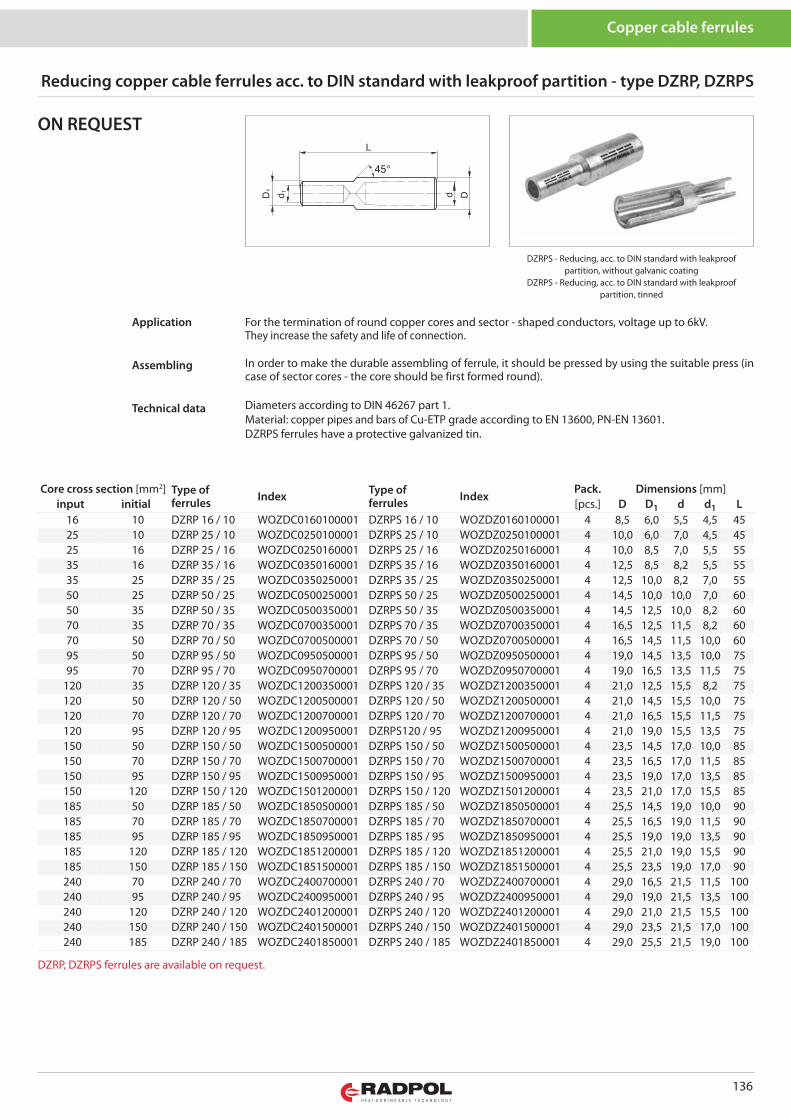
136
DZRPS - Reducing, acc. to DIN standard with leakproofpartition, without galvanic coating
DZRPS - Reducing, acc. to DIN standard with leakproofpartition, tinned
Reducing copper cable ferrules acc. to DIN standard with leakproof partition - type DZRP, DZRPS
Copper cable ferrules
For the termination of round copper cores and sector - shaped conductors, voltage up to 6kV. They increase the safety and life of connection.
In order to make the durable assembling of ferrule, it should be pressed by using the suitable press (incase of sector cores - the core should be first formed round).
Diameters according to DIN 46267 part 1.Material: copper pipes and bars of Cu-ETP grade according to EN 13600, PN-EN 13601.DZRPS ferrules have a protective galvanized tin.
Application
Assembling
Technical data
ON REQUEST
Core cross section [mm2] Type offerrules Index Type of
ferrules IndexPack. Dimensions [mm]
input initial [pcs.] D D1 d d1 L16 10 DZRP 16 / 10 WOZDC0160100001 DZRPS 16 / 10 WOZDZ0160100001 4 8,5 6,0 5,5 4,5 4525 10 DZRP 25 / 10 WOZDC0250100001 DZRPS 25 / 10 WOZDZ0250100001 4 10,0 6,0 7,0 4,5 4525 16 DZRP 25 / 16 WOZDC0250160001 DZRPS 25 / 16 WOZDZ0250160001 4 10,0 8,5 7,0 5,5 5535 16 DZRP 35 / 16 WOZDC0350160001 DZRPS 35 / 16 WOZDZ0350160001 4 12,5 8,5 8,2 5,5 5535 25 DZRP 35 / 25 WOZDC0350250001 DZRPS 35 / 25 WOZDZ0350250001 4 12,5 10,0 8,2 7,0 5550 25 DZRP 50 / 25 WOZDC0500250001 DZRPS 50 / 25 WOZDZ0500250001 4 14,5 10,0 10,0 7,0 6050 35 DZRP 50 / 35 WOZDC0500350001 DZRPS 50 / 35 WOZDZ0500350001 4 14,5 12,5 10,0 8,2 6070 35 DZRP 70 / 35 WOZDC0700350001 DZRPS 70 / 35 WOZDZ0700350001 4 16,5 12,5 11,5 8,2 6070 50 DZRP 70 / 50 WOZDC0700500001 DZRPS 70 / 50 WOZDZ0700500001 4 16,5 14,5 11,5 10,0 6095 50 DZRP 95 / 50 WOZDC0950500001 DZRPS 95 / 50 WOZDZ0950500001 4 19,0 14,5 13,5 10,0 7595 70 DZRP 95 / 70 WOZDC0950700001 DZRPS 95 / 70 WOZDZ0950700001 4 19,0 16,5 13,5 11,5 75
120 35 DZRP 120 / 35 WOZDC1200350001 DZRPS 120 / 35 WOZDZ1200350001 4 21,0 12,5 15,5 8,2 75120 50 DZRP 120 / 50 WOZDC1200500001 DZRPS 120 / 50 WOZDZ1200500001 4 21,0 14,5 15,5 10,0 75120 70 DZRP 120 / 70 WOZDC1200700001 DZRPS 120 / 70 WOZDZ1200700001 4 21,0 16,5 15,5 11,5 75120 95 DZRP 120 / 95 WOZDC1200950001 DZRPS120 / 95 WOZDZ1200950001 4 21,0 19,0 15,5 13,5 75150 50 DZRP 150 / 50 WOZDC1500500001 DZRPS 150 / 50 WOZDZ1500500001 4 23,5 14,5 17,0 10,0 85150 70 DZRP 150 / 70 WOZDC1500700001 DZRPS 150 / 70 WOZDZ1500700001 4 23,5 16,5 17,0 11,5 85150 95 DZRP 150 / 95 WOZDC1500950001 DZRPS 150 / 95 WOZDZ1500950001 4 23,5 19,0 17,0 13,5 85150 120 DZRP 150 / 120 WOZDC1501200001 DZRPS 150 / 120 WOZDZ1501200001 4 23,5 21,0 17,0 15,5 85185 50 DZRP 185 / 50 WOZDC1850500001 DZRPS 185 / 50 WOZDZ1850500001 4 25,5 14,5 19,0 10,0 90185 70 DZRP 185 / 70 WOZDC1850700001 DZRPS 185 / 70 WOZDZ1850700001 4 25,5 16,5 19,0 11,5 90185 95 DZRP 185 / 95 WOZDC1850950001 DZRPS 185 / 95 WOZDZ1850950001 4 25,5 19,0 19,0 13,5 90185 120 DZRP 185 / 120 WOZDC1851200001 DZRPS 185 / 120 WOZDZ1851200001 4 25,5 21,0 19,0 15,5 90185 150 DZRP 185 / 150 WOZDC1851500001 DZRPS 185 / 150 WOZDZ1851500001 4 25,5 23,5 19,0 17,0 90240 70 DZRP 240 / 70 WOZDC2400700001 DZRPS 240 / 70 WOZDZ2400700001 4 29,0 16,5 21,5 11,5 100240 95 DZRP 240 / 95 WOZDC2400950001 DZRPS 240 / 95 WOZDZ2400950001 4 29,0 19,0 21,5 13,5 100240 120 DZRP 240 / 120 WOZDC2401200001 DZRPS 240 / 120 WOZDZ2401200001 4 29,0 21,0 21,5 15,5 100240 150 DZRP 240 / 150 WOZDC2401500001 DZRPS 240 / 150 WOZDZ2401500001 4 29,0 23,5 21,5 17,0 100240 185 DZRP 240 / 185 WOZDC2401850001 DZRPS 240 / 185 WOZDZ2401850001 4 29,0 25,5 21,5 19,0 100
DZRP, DZRPS ferrules are available on request.
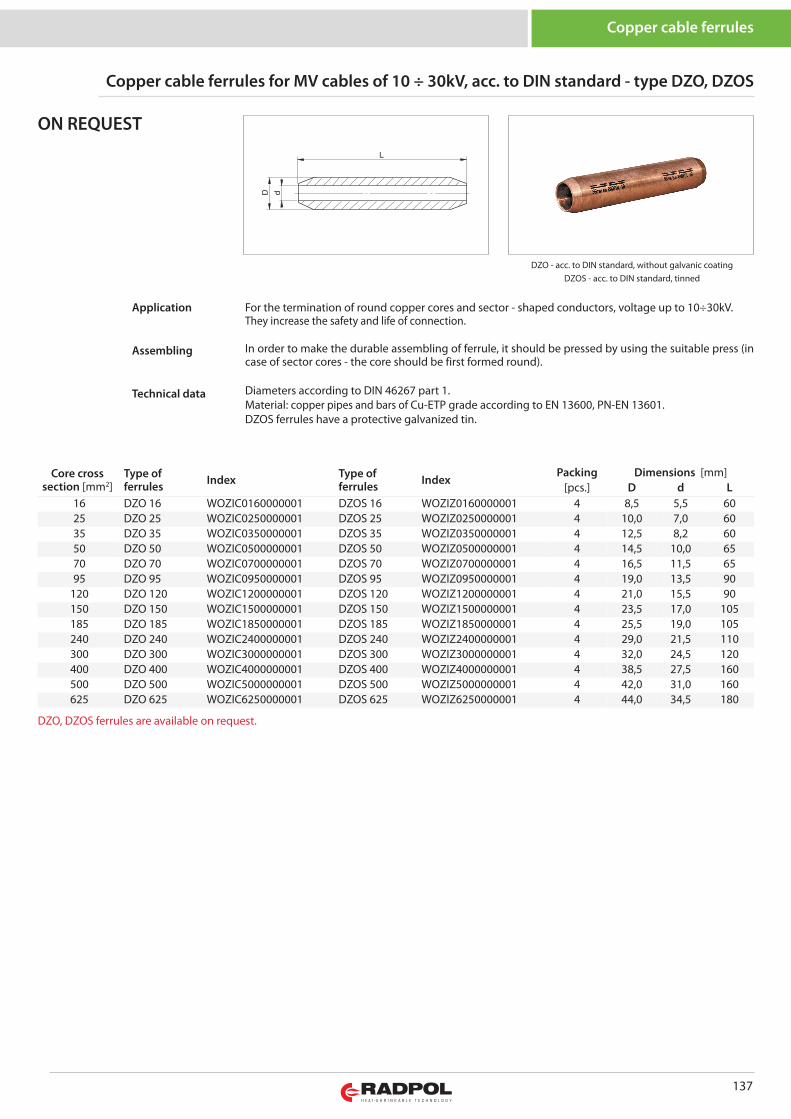
137
DZO - acc. to DIN standard, without galvanic coatingDZOS - acc. to DIN standard, tinned
Copper cable ferrules for MV cables of 10 ÷ 30kV, acc. to DIN standard - type DZO, DZOS
Copper cable ferrules
For the termination of round copper cores and sector - shaped conductors, voltage up to 10÷30kV. They increase the safety and life of connection.
In order to make the durable assembling of ferrule, it should be pressed by using the suitable press (incase of sector cores - the core should be first formed round).
Diameters according to DIN 46267 part 1.Material: copper pipes and bars of Cu-ETP grade according to EN 13600, PN-EN 13601.DZOS ferrules have a protective galvanized tin.
Application
Assembling
Technical data
ON REQUEST
Core crosssection [mm2]
Type offerrules Index Type of
ferrules IndexPacking Dimensions [mm]
[pcs.] D d L16 DZO 16 WOZIC0160000001 DZOS 16 WOZIZ0160000001 4 8,5 5,5 6025 DZO 25 WOZIC0250000001 DZOS 25 WOZIZ0250000001 4 10,0 7,0 6035 DZO 35 WOZIC0350000001 DZOS 35 WOZIZ0350000001 4 12,5 8,2 6050 DZO 50 WOZIC0500000001 DZOS 50 WOZIZ0500000001 4 14,5 10,0 6570 DZO 70 WOZIC0700000001 DZOS 70 WOZIZ0700000001 4 16,5 11,5 6595 DZO 95 WOZIC0950000001 DZOS 95 WOZIZ0950000001 4 19,0 13,5 90
120 DZO 120 WOZIC1200000001 DZOS 120 WOZIZ1200000001 4 21,0 15,5 90150 DZO 150 WOZIC1500000001 DZOS 150 WOZIZ1500000001 4 23,5 17,0 105185 DZO 185 WOZIC1850000001 DZOS 185 WOZIZ1850000001 4 25,5 19,0 105240 DZO 240 WOZIC2400000001 DZOS 240 WOZIZ2400000001 4 29,0 21,5 110300 DZO 300 WOZIC3000000001 DZOS 300 WOZIZ3000000001 4 32,0 24,5 120400 DZO 400 WOZIC4000000001 DZOS 400 WOZIZ4000000001 4 38,5 27,5 160500 DZO 500 WOZIC5000000001 DZOS 500 WOZIZ5000000001 4 42,0 31,0 160625 DZO 625 WOZIC6250000001 DZOS 625 WOZIZ6250000001 4 44,0 34,5 180
DZO, DZOS ferrules are available on request.
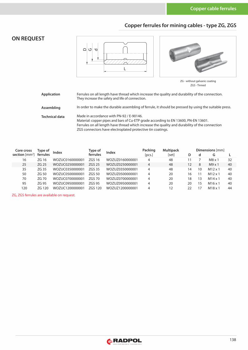
138
Copper cable ferrules
Copper ferrules for mining cables - type ZG, ZGS
ZG - without galvanic coatingZGS - Tinned
Ferrules on all length have thread which increase the quality and durability of the connection.They increase the safety and life of connection.
In order to make the durable assembling of ferrule, it should be pressed by using the suitable press.
Made in accordance with PN-92 / E-90146.Material: copper pipes and bars of Cu-ETP grade according to EN 13600, PN-EN 13601.Ferrules on all length have thread which increase the quality and durability of the connectionZGS connectors have electroplated protective tin coatings.
Application
Assembling
Technical data
ON REQUEST
Core crosssection [mm2]
Type offerrules Index Type of
ferrules IndexPacking Multipack
[set]Dimensions [mm]
[pcs.] D d G L16 ZG 16 WOZUC0160000001 ZGS 16 WOZUZ0160000001 4 48 11 7 M8 x 1 3225 ZG 25 WOZUC0250000001 ZGS 25 WOZUZ0250000001 4 48 12 8 M9 x 1 4035 ZG 35 WOZUC0350000001 ZGS 35 WOZUZ0350000001 4 48 14 10 M12 x 1 4050 ZG 50 WOZUC0500000001 ZGS 50 WOZUZ0500000001 4 20 16 11 M12 x 1 4070 ZG 70 WOZUC0700000001 ZGS 70 WOZUZ0700000001 4 20 18 13 M14 x 1 4095 ZG 95 WOZUC0950000001 ZGS 95 WOZUZ0950000001 4 20 20 15 M16 x 1 40
120 ZG 120 WOZUC1200000001 ZGS 120 WOZUZ1200000001 4 12 22 17 M18 x 1 44
ZG, ZGS ferrules are available on request.
D G
L
d
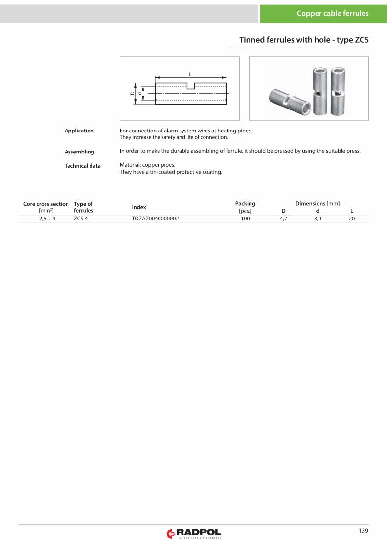
139
Core cross section[mm2]
Type offerrules Index
Packing Dimensions [mm][pcs.] D d L
2,5 ÷ 4 ZCS 4 TOZAZ0040000002 100 4,7 3,0 20
Tinned ferrules with hole - type ZCS
Copper cable ferrules
For connection of alarm system wires at heating pipes.They increase the safety and life of connection.
In order to make the durable assembling of ferrule, it should be pressed by using the suitable press.
Material: copper pipes.They have a tin-coated protective coating.
Application
Assembling
Technical data
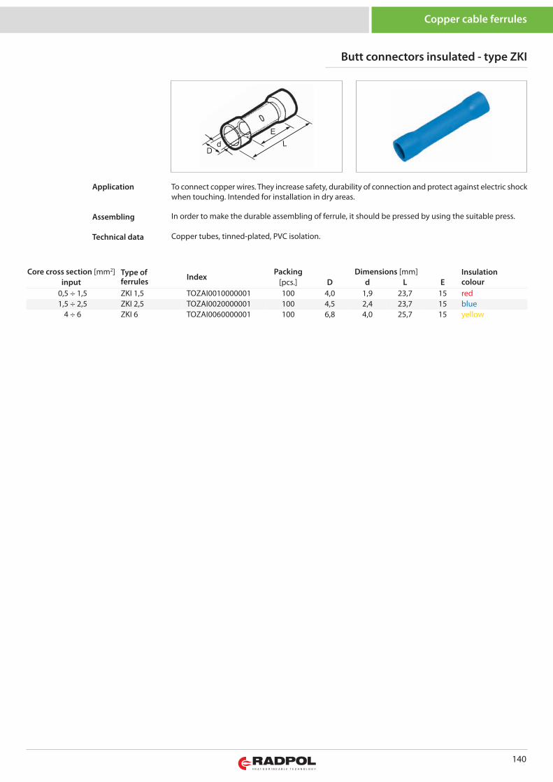
140
Core cross section [mm2] Type offerrules Index
Packing Dimensions [mm] Insulationcolourinput [pcs.] D d L E
0,5 ÷ 1,5 ZKI 1,5 TOZAI0010000001 100 4,0 1,9 23,7 15 red1,5 ÷ 2,5 ZKI 2,5 TOZAI0020000001 100 4,5 2,4 23,7 15 blue
4 ÷ 6 ZKI 6 TOZAI0060000001 100 6,8 4,0 25,7 15 yellow
Butt connectors insulated - type ZKI
Copper cable ferrules
To connect copper wires. They increase safety, durability of connection and protect against electric shockwhen touching. Intended for installation in dry areas.
In order to make the durable assembling of ferrule, it should be pressed by using the suitable press.
Copper tubes, tinned-plated, PVC isolation.
Application
Assembling
Technical data
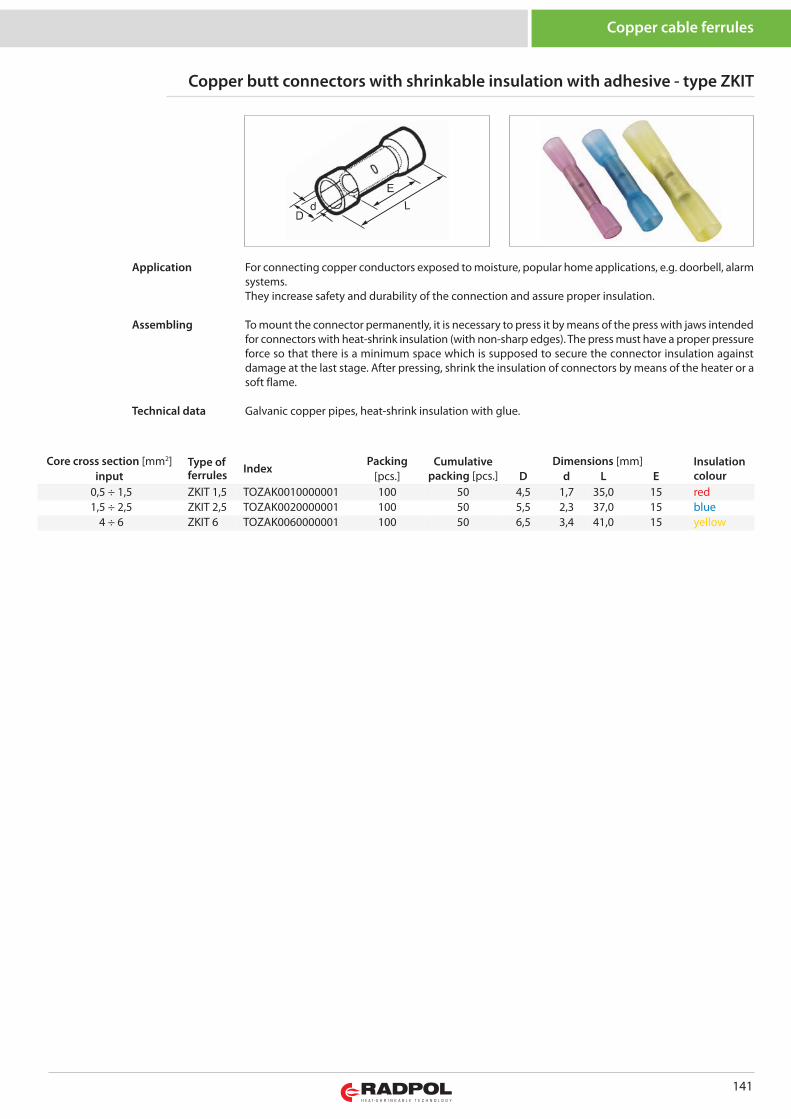
141
Core cross section [mm2] Type offerrules Index
Packing Cumulativepacking [pcs.]
Dimensions [mm] Insulationcolourinput [pcs.] D d L E
0,5 ÷ 1,5 ZKIT 1,5 TOZAK0010000001 100 50 4,5 1,7 35,0 15 red1,5 ÷ 2,5 ZKIT 2,5 TOZAK0020000001 100 50 5,5 2,3 37,0 15 blue
4 ÷ 6 ZKIT 6 TOZAK0060000001 100 50 6,5 3,4 41,0 15 yellow
Copper butt connectors with shrinkable insulation with adhesive - type ZKIT
Copper cable ferrules
For connecting copper conductors exposed to moisture, popular home applications, e.g. doorbell, alarmsystems.They increase safety and durability of the connection and assure proper insulation.
To mount the connector permanently, it is necessary to press it by means of the press with jaws intendedfor connectors with heat-shrink insulation (with non-sharp edges). The press must have a proper pressureforce so that there is a minimum space which is supposed to secure the connector insulation againstdamage at the last stage. After pressing, shrink the insulation of connectors by means of the heater or asoft flame.
Galvanic copper pipes, heat-shrink insulation with glue.
Application
Assembling
Technical data
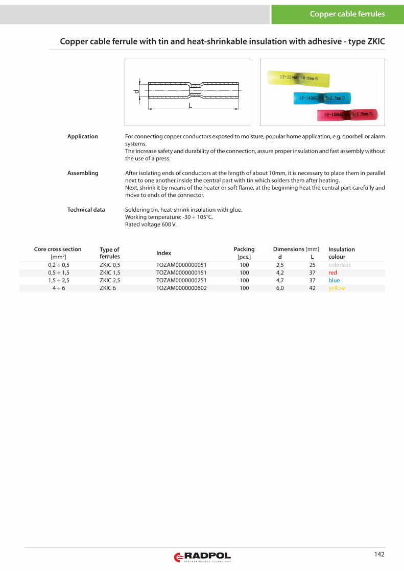
142
Copper cable ferrules
Core cross section Type offerrules Index
Packing Dimensions [mm] Insulationcolour[mm2] [pcs.] d L
0,2 ÷ 0,5 ZKIC 0,5 TOZAM0000000051 100 2,5 25 colorless0,5 ÷ 1,5 ZKIC 1,5 TOZAM0000000151 100 4,2 37 red1,5 ÷ 2,5 ZKIC 2,5 TOZAM0000000251 100 4,7 37 blue
4 ÷ 6 ZKIC 6 TOZAM0000000602 100 6,0 42 yellow
L
d
Copper cable ferrule with tin and heat-shrinkable insulation with adhesive - type ZKIC
For connecting copper conductors exposed to moisture, popular home application, e.g. doorbell or alarmsystems.The increase safety and durability of the connection, assure proper insulation and fast assembly withoutthe use of a press.
After isolating ends of conductors at the length of about 10mm, it is necessary to place them in parallelnext to one another inside the central part with tin which solders them after heating. Next, shrink it by means of the heater or soft flame, at the beginning heat the central part carefully andmove to ends of the connector.
Soldering tin, heat-shrink insulation with glue.Working temperature: -30 ÷ 105°C.Rated voltage 600 V.
Application
Assembling
Technical data
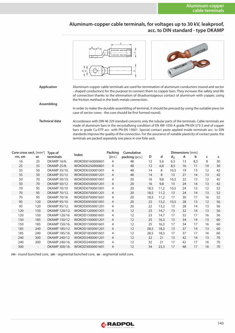
143
b c
z
Core cross sect. [mm2] Type ofterminals Index
Packing Cumulativepacking [pcs.]
Dimensions [mm]rm, sm se [pcs.] D d d1 A b c z
16 25 DKAMP 16/6. WOKDD0160000601 4 48 12 5,6 6,5 13 8,5 8 3025 35 DKAMP 25/8. WOKDD0250000801 4 48 12 6,8 8,5 16 11 10 3035 50 DKAMP 35/10. WOKDD0350001001 4 48 14 8 10,5 19 13 12 4235 50 DKAMP 35/12 WOKDD0350001201 4 48 14 8 13 21 14 13 4250 70 DKAMP 50/10. WOKDD0500001001 4 20 16 9,8 10,5 22 13 12 4250 70 DKAMP 50/12 WOKDD0500001201 4 20 16 9,8 13 24 14 13 4270 95 DKAMP 70/10 WOKDD0700001001 4 20 18,5 11,2 10,5 24 13 12 5270 95 DKAMP 70/12. WOKDD0700001201 4 20 18,5 11,2 13 24 14 13 5270 95 DKAMP 70/16 WOKDD0700001601 4 20 18,5 11,2 17 30 17 16 5295 120 DKAMP 95/10 WOKDD0950001001 4 20 22 13,2 10,5 28 13 12 5695 120 DKAMP 95/12. WOKDD0950001201 4 20 22 13,2 13 28 14 13 56
120 150 DKAMP 120/12. WOKDD1200001201 4 12 23 14,7 13 32 14 13 56120 150 DKAMP 120/16 WOKDD1500001601 4 12 23 14,7 17 32 17 16 56150 185 DKAMP 150/12 WOKDD1500001201 4 12 25 16,3 13 34 14 13 60150 185 DKAMP 150/16. WOKDD1500001601 4 12 25 16,3 17 34 17 16 60185 240 DKAMP 185/12 WOKDD1850001201 4 12 28,5 18,3 13 37 14 13 60185 240 DKAMP 185/16. WOKDD1850001601 4 12 28,5 18,3 17 37 17 16 60240 300 DKAMP 240/12 WOKDD2400001201 4 12 32 21 13 42 14 13 70240 300 DKAMP 240/16. WOKDD2400001601 4 12 32 21 17 42 17 16 70300 - DKAMP 300/16. WOKDD3000001601 4 12 34 23,3 17 48 17 16 70
Aluminum-copper cable terminals, for voltages up to 30 kV, leakproof,acc. to DIN standard - type DKAMP
Aluminum-coppercable terminals
Aluminum-copper cable terminals are used for termination of aluminum conductors (round and sector- shaped conductors) for the purpose to connect them to copper bars. They increase the safety and lifeof connection thanks to the elimination of disadvantageous contact of aluminum with copper, usingthe friction method in the both metals connection.
In order to make the durable assembling of terminal, it should be pressed by using the suitable press (incase of sector cores - the core should be first formed round).
Accordanace with DIN 46 329 standard concerns only the tubular parts of the terminals. Cable terminals aremade of aluminum bars in the recrystallizing condition of EN AW-1050 A grade PN-EN 573-3 and of copperbars in grade Cu-ETP acc. with PN-EN 13601. Special contact paste applied inside terminals acc. to DINstandards improve the quality of the connection. For the assurance of suitable plasticity of contact paste, theterminals are packed separately one piece in one folie sack.
Application
Assembling
Technical data
rm - round bunched core, sm - segmental bunched core, se - segmental solid core.
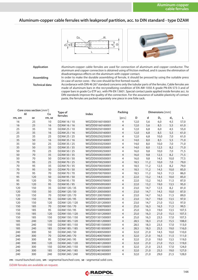
144
Aluminum-coppercable ferrules
Core cross section [mm2]Type offerrules Index
Packing Dimensions [mm]Al Cu
rm, sm se rm, se [pcs.] D d D1 d1 L16 25 10 DZAM 16 / 10 WOZDD0160100001 4 12,0 5,6 6,0 4,5 57,016 25 16 DZAM 16 / 16 WOZDD0160160001 4 12,0 5,6 8,5 5,5 61,025 35 10 DZAM 25 / 10 WOZDD0250100001 4 12,0 6,8 6,0 4,5 55,025 35 16 DZAM 25 / 16 WOZDD0250160001 4 12,0 6,8 8,5 5,5 61,025 35 25 DZAM 25 / 25 WOZDD0250250001 4 12,0 6,8 10,0 7,0 61,035 50 16 DZAM 35 / 16 WOZDD0350160001 4 14,0 8,0 8,5 5,5 71,035 50 25 DZAM 35 / 25 WOZDD0350250001 4 14,0 8,0 10,0 7,0 71,035 50 35 DZAM 35 / 35 WOZDD0350350001 4 14,0 8,0 12,5 8,2 71,050 70 25 DZAM 50 / 25 WOZDD0500250001 4 16,0 9,8 10,0 7,0 71,550 70 35 DZAM 50 / 35 WOZDD0500350001 4 16,0 9,8 12,5 8,2 71,550 70 50 DZAM 50 / 50 WOZDD0500500001 4 16,0 9,8 14,5 10,0 77,570 95 25 DZAM 70 / 25 WOZDD0700250001 4 18,5 11,2 10,0 7,0 79,070 95 35 DZAM 70 / 35 WOZDD0700350001 4 18,5 11,2 12,5 8,2 79,070 95 50 DZAM 70 / 50 WOZDD0700500001 4 18,5 11,2 14,5 10,0 85,070 95 70 DZAM 70 / 70 WOZDD0700700001 4 18,5 11,2 16,5 11,5 86,095 120 50 DZAM 95 / 50 WOZDD0950500001 4 22,0 13,2 14,5 10,0 85,095 120 70 DZAM 95 / 70 WOZDD0950700001 4 22,0 13,2 16,5 11,5 87,095 120 95 DZAM 95 / 95 WOZDD0950950001 4 22,0 13,2 19,0 13,5 95,0
120 150 35 DZAM 120 / 35 WOZDD1200350001 4 23,0 14,7 12,5 8,2 81,0120 150 50 DZAM 120 / 50 WOZDD1200500001 4 23,0 14,7 14,5 10,0 87,0120 150 70 DZAM 120 / 70 WOZDD1200700001 4 23,0 14,7 16,5 11,5 89,0120 150 95 DZAM 120 / 95 WOZDD1200950001 4 23,0 14,7 19,0 13,5 97,0120 150 120 DZAM 120 / 120 WOZDD1201200001 4 23,0 14,7 21,0 15,5 97,0150 185 70 DZAM 150 / 70 WOZDD1500700001 4 25,0 16,3 16,5 11,5 99,5150 185 95 DZAM 150 / 95 WOZDD1500950001 4 25,0 16,3 19,0 13,5 107,5150 185 120 DZAM 150 / 120 WOZDD1501200001 4 25,0 16,3 21,0 15,5 107,5150 185 150 DZAM 150 / 150 WOZDD1501500001 4 25,0 16,3 23,5 17,0 107,5185 240 120 DZAM 185 / 120 WOZDD1851200001 4 28,5 18,3 21,0 15,5 108,0185 240 150 DZAM 185 / 150 WOZDD1851500001 4 28,5 18,3 23,5 17,0 113,0185 240 185 DZAM 185 / 185 WOZDD1851850001 4 28,5 18,3 25,5 19,0 116,0240 300 50 DZAM 240 / 50 WOZDD2400500001 4 32,0 21,0 14,5 10,0 110,0240 300 70 DZAM 240 / 70 WOZDD2400700001 4 32,0 21,0 16,5 11,5 111,0240 300 95 DZAM 240 / 95 WOZDD2400950001 4 32,0 21,0 19,0 13,5 119,0240 300 120 DZAM 240 / 120 WOZDD2401200001 4 32,0 21,0 21,0 15,5 119,0240 300 150 DZAM 240 / 150 WOZDD2401500001 4 32,0 21,0 23,5 17,0 124,0240 300 185 DZAM 240 / 185 WOZDD2401850001 4 32,0 21,0 25,5 19,0 127,0240 300 240 DZAM 240 / 240 WOZDD2402400001 4 32,0 21,0 29,0 21,5 128,0
Aluminum-copper cable ferrules with leakproof partition, acc. to DIN standard - type DZAM
rm - round bunched core, sm - segmental bunched core, se - segmental solid core.
Aluminum-copper cable ferrules are used for connection of aluminum and copper conductor. Thealuminum and copper connection is obtained using of friction method, and it causes the elimination ofdisadvantageous effects on the aluminum with copper contact.In order to make the durable assembling of ferrule, it should be pressed by using the suitable press(in case of sector cores - the core should be first formed round).Accordanace with DIN 46 267 standard concerns only the tubular parts of the ferrules. Cable ferrules aremade of aluminum bars in the recrystallizing condition of EN AW-1050 A grade PN-EN 573-3 and ofcopper bars in grade Cu-ETP acc. with PN-EN 13601. Special contact paste applied inside ferrules acc. toDIN standards improve the quality of the connection. For the assurance of suitable plasticity of contactpaste, the ferrules are packed separately one piece in one folie sack.
Application
Assembling
Technical data
DZAM ferrules are available on request.
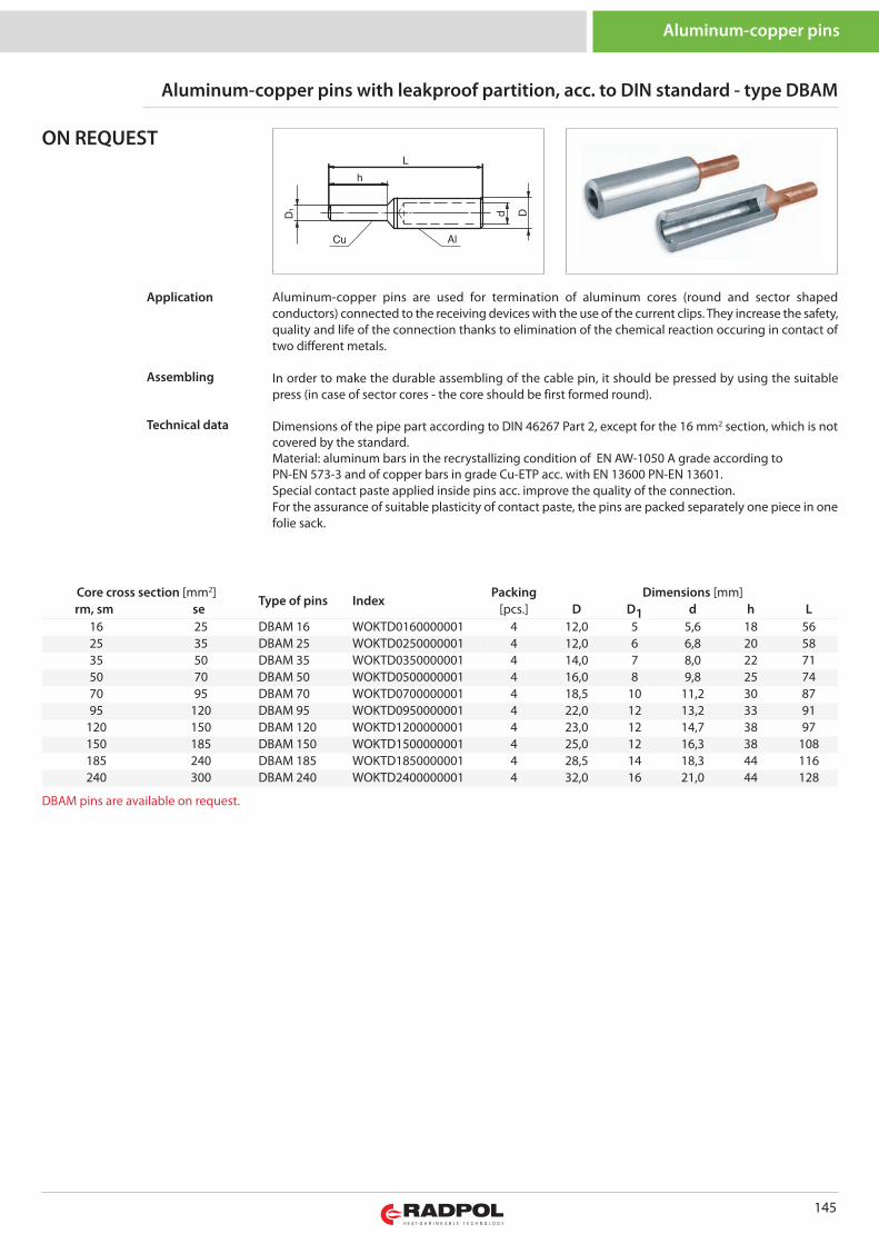
145
Aluminum-copper pins
Aluminum-copper pins with leakproof partition, acc. to DIN standard - type DBAM
Aluminum-copper pins are used for termination of aluminum cores (round and sector shapedconductors) connected to the receiving devices with the use of the current clips. They increase the safety,quality and life of the connection thanks to elimination of the chemical reaction occuring in contact oftwo different metals.
In order to make the durable assembling of the cable pin, it should be pressed by using the suitablepress (in case of sector cores - the core should be first formed round).
Dimensions of the pipe part according to DIN 46267 Part 2, except for the 16 mm2 section, which is notcovered by the standard. Material: aluminum bars in the recrystallizing condition of EN AW-1050 A grade according toPN-EN 573-3 and of copper bars in grade Cu-ETP acc. with EN 13600 PN-EN 13601.Special contact paste applied inside pins acc. improve the quality of the connection.For the assurance of suitable plasticity of contact paste, the pins are packed separately one piece in onefolie sack.
Application
Assembling
Technical data
ON REQUEST
Core cross section [mm2]Type of pins Index
Packing Dimensions [mm]rm, sm se [pcs.] D D1 d h L
16 25 DBAM 16 WOKTD0160000001 4 12,0 5 5,6 18 5625 35 DBAM 25 WOKTD0250000001 4 12,0 6 6,8 20 5835 50 DBAM 35 WOKTD0350000001 4 14,0 7 8,0 22 7150 70 DBAM 50 WOKTD0500000001 4 16,0 8 9,8 25 7470 95 DBAM 70 WOKTD0700000001 4 18,5 10 11,2 30 8795 120 DBAM 95 WOKTD0950000001 4 22,0 12 13,2 33 91
120 150 DBAM 120 WOKTD1200000001 4 23,0 12 14,7 38 97150 185 DBAM 150 WOKTD1500000001 4 25,0 12 16,3 38 108185 240 DBAM 185 WOKTD1850000001 4 28,5 14 18,3 44 116240 300 DBAM 240 WOKTD2400000001 4 32,0 16 21,0 44 128
DBAM pins are available on request.
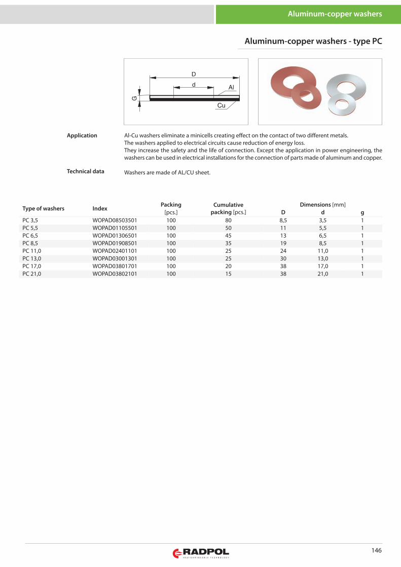
146
Aluminum-copper washers
Aluminum-copper washers - type PC
Type of washers IndexPacking Cumulative
packing [pcs.]Dimensions [mm]
[pcs.] D d gPC 3,5 WOPAD08503501 100 80 8,5 3,5 1PC 5,5 WOPAD01105501 100 50 11 5,5 1PC 6,5 WOPAD01306501 100 45 13 6,5 1PC 8,5 WOPAD01908501 100 35 19 8,5 1PC 11,0 WOPAD02401101 100 25 24 11,0 1PC 13,0 WOPAD03001301 100 25 30 13,0 1PC 17,0 WOPAD03801701 100 20 38 17,0 1PC 21,0 WOPAD03802101 100 15 38 21,0 1
Al-Cu washers eliminate a minicells creating effect on the contact of two different metals.The washers applied to electrical circuits cause reduction of energy loss.They increase the safety and the life of connection. Except the application in power engineering, thewashers can be used in electrical installations for the connection of parts made of aluminum and copper.
Washers are made of AL/CU sheet.
Application
Technical data
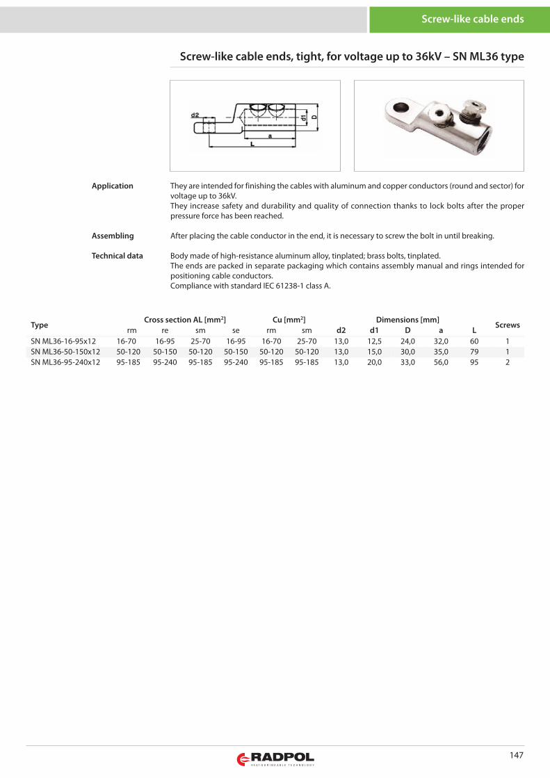
147
Screw-like cable ends
Screw-like cable ends, tight, for voltage up to 36kV – SN ML36 type
TypeCross section AL [mm2] Cu [mm2] Dimensions [mm]
Screwsrm re sm se rm sm d2 d1 D a L
SN ML36-16-95x12 16-70 16-95 25-70 16-95 16-70 25-70 13,0 12,5 24,0 32,0 60 1SN ML36-50-150x12 50-120 50-150 50-120 50-150 50-120 50-120 13,0 15,0 30,0 35,0 79 1SN ML36-95-240x12 95-185 95-240 95-185 95-240 95-185 95-185 13,0 20,0 33,0 56,0 95 2
They are intended for finishing the cables with aluminum and copper conductors (round and sector) forvoltage up to 36kV.They increase safety and durability and quality of connection thanks to lock bolts after the properpressure force has been reached.
After placing the cable conductor in the end, it is necessary to screw the bolt in until breaking.
Body made of high-resistance aluminum alloy, tinplated; brass bolts, tinplated.The ends are packed in separate packaging which contains assembly manual and rings intended forpositioning cable conductors.Compliance with standard IEC 61238-1 class A.
Application
Assembling
Technical data
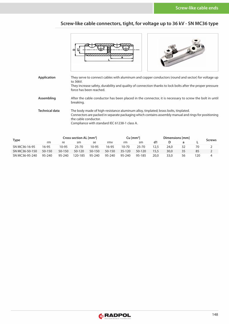
148
Screw-like cable ends
Screw-like cable connectors, tight, for voltage up to 36 kV - SN MC36 type
TypeCross section AL [mm2] Cu [mm2] Dimensions [mm]
Screwsrm re sm se rmv rm sm d1 D a L
SN MC36-16-95 16-95 10-95 25-70 10-95 16-95 10-70 25-70 12,5 24,0 32 70 2SN MC36-50-150 50-150 50-150 50-120 50-150 50-150 35-120 50-120 15,5 30,0 35 85 2SN MC36-95-240 95-240 95-240 120-185 95-240 95-240 95-240 95-185 20,0 33,0 56 120 4
They serve to connect cables with aluminum and copper conductors (round and sector) for voltage upto 36kV.They increase safety, durability and quality of connection thanks to lock bolts after the proper pressureforce has been reached.
After the cable conductor has been placed in the connector, it is necessary to screw the bolt in untilbreaking.
The body made of high-resistance aluminum alloy, tinplated; brass bolts, tinplated.Connectors are packed in separate packaging which contains assembly manual and rings for positioningthe cable conductor.Compliance with standard IEC 61238-1 class A.
Application
Assembling
Technical data
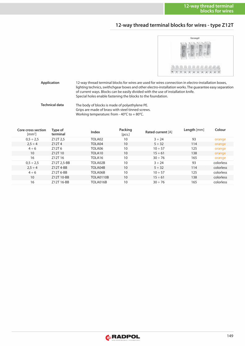
149
12-way thread terminalblocks for wires
12-way thread terminal blocks for wires - type Z12T
Core cross section[mm2]
Type of terminal Index
PackingRated current [A]
Length [mm] Colour[pcs.]
0,5 ÷ 2,5 Z12T 2,5 TOLA02 10 3 ÷ 24 93 orange2,5 ÷ 4 Z12T 4 TOLA04 10 5 ÷ 32 114 orange4 ÷ 6 Z12T 6 TOLA06 10 10 ÷ 57 125 orange
10 Z12T 10 TOLA10 10 15 ÷ 61 138 orange16 Z12T 16 TOLA16 10 30 ÷ 76 165 orange
0,5 ÷ 2,5 Z12T 2,5-BB TOLA02B 10 3 ÷ 24 93 colorless2,5 ÷ 4 Z12T 4-BB TOLA04B 10 5 ÷ 32 114 colorless4 ÷ 6 Z12T 6-BB TOLA06B 10 10 ÷ 57 125 colorless
10 Z12T 10-BB TOLA0110B 10 15 ÷ 61 138 colorless16 Z12T 16-BB TOLA016B 10 30 ÷ 76 165 colorless
12-way thread terminal blocks for wires are used for wires connection in electro-installation boxes,lighting technics, swithchgear boxes and other electro-installation works. The guarantee easy separationof current ways. Blocks can be easily divided with the use of installation knife. Special holes enable fastening the blocks to the foundation.
The body of blocks is made of polyethylene PE.Grips are made of brass with steel tinned screws.Working temperature: from - 40°C to + 80°C.
Application
Technical data
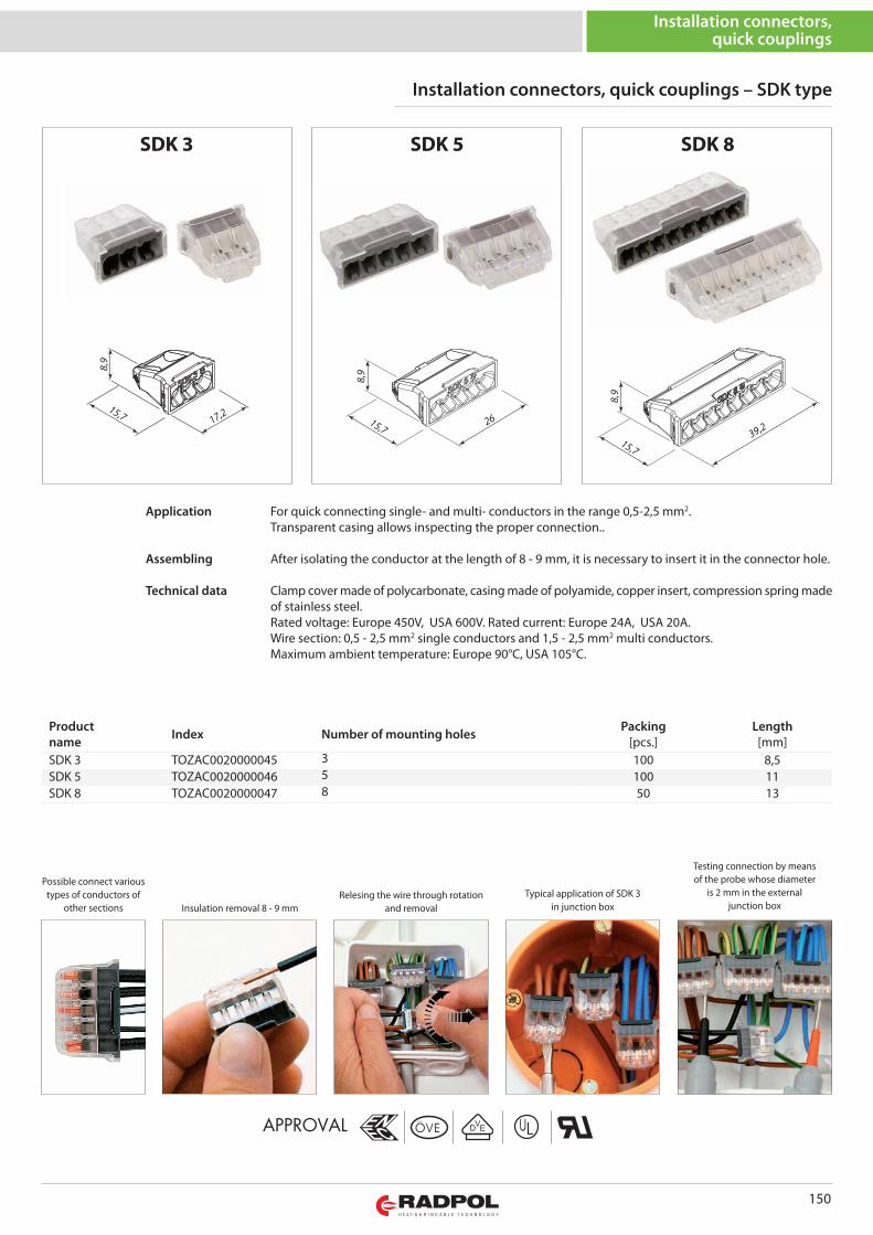
SDK 5
APPROVAL
SDK 3
Possible connect varioustypes of conductors of
other sections
SDK 8
Insulation removal 8 - 9 mmRelesing the wire through rotation
and removalTypical application of SDK 3
in junction box
Testing connection by meansof the probe whose diameter
is 2 mm in the externaljunction box
8,9
17,215,7
8,9
2615,7
8,9
39,2
15,7
150
Installation connectors,quick couplings
Installation connectors, quick couplings – SDK type
For quick connecting single- and multi- conductors in the range 0,5-2,5 mm2.Transparent casing allows inspecting the proper connection..
After isolating the conductor at the length of 8 - 9 mm, it is necessary to insert it in the connector hole.
Clamp cover made of polycarbonate, casing made of polyamide, copper insert, compression spring madeof stainless steel.Rated voltage: Europe 450V, USA 600V. Rated current: Europe 24A, USA 20A.Wire section: 0,5 - 2,5 mm2 single conductors and 1,5 - 2,5 mm2 multi conductors.Maximum ambient temperature: Europe 90°C, USA 105°C.
Application
Assembling
Technical data
Productname Index Number of mounting holes Packing
[pcs.]Length[mm]
SDK 3 TOZAC0020000045 3 100 8,5SDK 5 TOZAC0020000046 5 100 11SDK 8 TOZAC0020000047 8 50 13
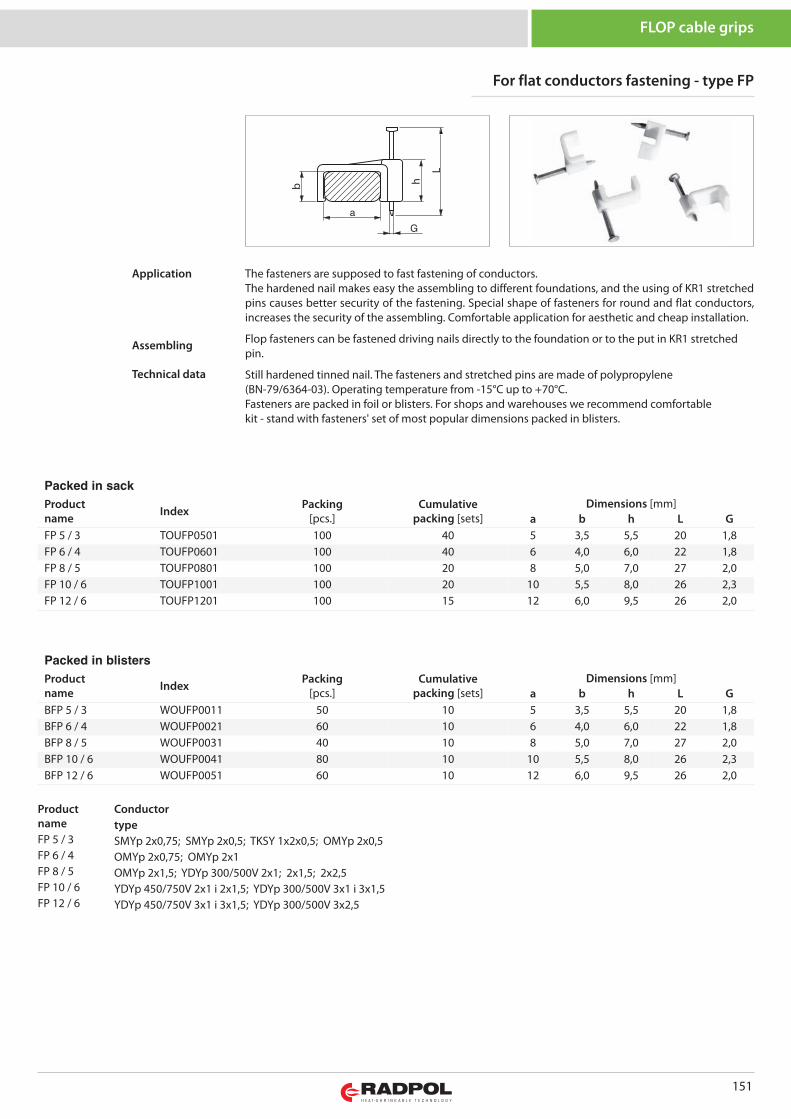
For flat conductors fastening - type FP
151
FLOP cable grips
Packed in sack
Productname Index Packing
[pcs.]Cumulative
packing [sets]Dimensions [mm]
a b h L GFP 5 / 3 TOUFP0501 100 40 5 3,5 5,5 20 1,8FP 6 / 4 TOUFP0601 100 40 6 4,0 6,0 22 1,8FP 8 / 5 TOUFP0801 100 20 8 5,0 7,0 27 2,0FP 10 / 6 TOUFP1001 100 20 10 5,5 8,0 26 2,3FP 12 / 6 TOUFP1201 100 15 12 6,0 9,5 26 2,0
ProductnameFP 5 / 3FP 6 / 4FP 8 / 5FP 10 / 6FP 12 / 6
ConductortypeSMYp 2x0,75; SMYp 2x0,5; TKSY 1x2x0,5; OMYp 2x0,5OMYp 2x0,75; OMYp 2x1OMYp 2x1,5; YDYp 300/500V 2x1; 2x1,5; 2x2,5YDYp 450/750V 2x1 i 2x1,5; YDYp 300/500V 3x1 i 3x1,5YDYp 450/750V 3x1 i 3x1,5; YDYp 300/500V 3x2,5
The fasteners are supposed to fast fastening of conductors.The hardened nail makes easy the assembling to different foundations, and the using of KR1 stretchedpins causes better security of the fastening. Special shape of fasteners for round and flat conductors,increases the security of the assembling. Comfortable application for aesthetic and cheap installation.
Flop fasteners can be fastened driving nails directly to the foundation or to the put in KR1 stretchedpin.
Still hardened tinned nail. The fasteners and stretched pins are made of polypropylene(BN-79/6364-03). Operating temperature from -15°C up to +70°C.Fasteners are packed in foil or blisters. For shops and warehouses we recommend comfortablekit - stand with fasteners' set of most popular dimensions packed in blisters.
Application
Assembling
Technical data
Packed in blisters
Productname Index Packing
[pcs.]Cumulative
packing [sets]Dimensions [mm]
a b h L GBFP 5 / 3 WOUFP0011 50 10 5 3,5 5,5 20 1,8BFP 6 / 4 WOUFP0021 60 10 6 4,0 6,0 22 1,8BFP 8 / 5 WOUFP0031 40 10 8 5,0 7,0 27 2,0BFP 10 / 6 WOUFP0041 80 10 10 5,5 8,0 26 2,3BFP 12 / 6 WOUFP0051 60 10 12 6,0 9,5 26 2,0
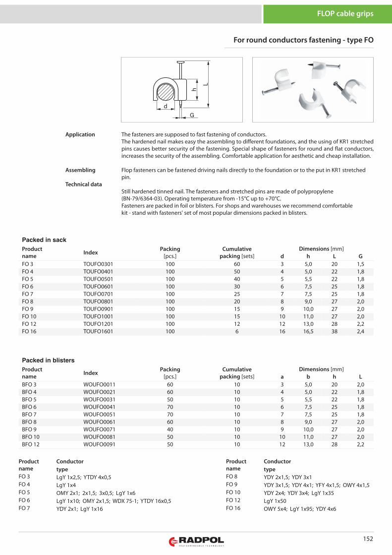
152
FLOP cable grips
Packed in sack
Productname Index Packing
[pcs.]Cumulative
packing [sets]Dimensions [mm]
d h L GFO 3 TOUFO0301 100 60 3 5,0 20 1,5FO 4 TOUFO0401 100 50 4 5,0 22 1,8FO 5 TOUFO0501 100 40 5 5,5 22 1,8FO 6 TOUFO0601 100 30 6 7,5 25 1,8FO 7 TOUFO0701 100 25 7 7,5 25 1,8FO 8 TOUFO0801 100 20 8 9,0 27 2,0FO 9 TOUFO0901 100 15 9 10,0 27 2,0FO 10 TOUFO1001 100 15 10 11,0 27 2,0FO 12 TOUFO1201 100 12 12 13,0 28 2,2FO 16 TOUFO1601 100 6 16 16,5 38 2,4
ProductnameFO 3FO 4FO 5FO 6FO 7
ConductortypeLgY 1x2,5; YTDY 4x0,5LgY 1x4OMY 2x1; 2x1,5; 3x0,5; LgY 1x6LgY 1x10; OMY 2x1,5; WDX 75-1; YTDY 16x0,5YDY 2x1; LgY 1x16
ProductnameFO 8FO 9FO 10FO 12FO 16
ConductortypeYDY 2x1,5; YDY 3x1YDY 3x1,5; YDY 4x1; YFY 4x1,5; OWY 4x1,5YDY 2x4; YDY 3x4; LgY 1x35LgY 1x50OWY 5x4; LgY 1x95; YDY 4x6
For round conductors fastening - type FO
The fasteners are supposed to fast fastening of conductors.The hardened nail makes easy the assembling to different foundations, and the using of KR1 stretchedpins causes better security of the fastening. Special shape of fasteners for round and flat conductors,increases the security of the assembling. Comfortable application for aesthetic and cheap installation.
Flop fasteners can be fastened driving nails directly to the foundation or to the put in KR1 stretchedpin.
Still hardened tinned nail. The fasteners and stretched pins are made of polypropylene(BN-79/6364-03). Operating temperature from -15°C up to +70°C.Fasteners are packed in foil or blisters. For shops and warehouses we recommend comfortablekit - stand with fasteners' set of most popular dimensions packed in blisters.
Application
Assembling
Technical data
Packed in blisters
Productname Index Packing
[pcs.]Cumulative
packing [sets]Dimensions [mm]
a b h LBFO 3 WOUFO0011 60 10 3 5,0 20 2,0BFO 4 WOUFO0021 60 10 4 5,0 22 1,8BFO 5 WOUFO0031 50 10 5 5,5 22 1,8BFO 6 WOUFO0041 70 10 6 7,5 25 1,8BFO 7 WOUFO0051 70 10 7 7,5 25 1,8BFO 8 WOUFO0061 60 10 8 9,0 27 2,0BFO 9 WOUFO0071 40 10 9 10,0 27 2,0BFO 10 WOUFO0081 50 10 10 11,0 27 2,0BFO 12 WOUFO0091 50 10 12 13,0 28 2,2
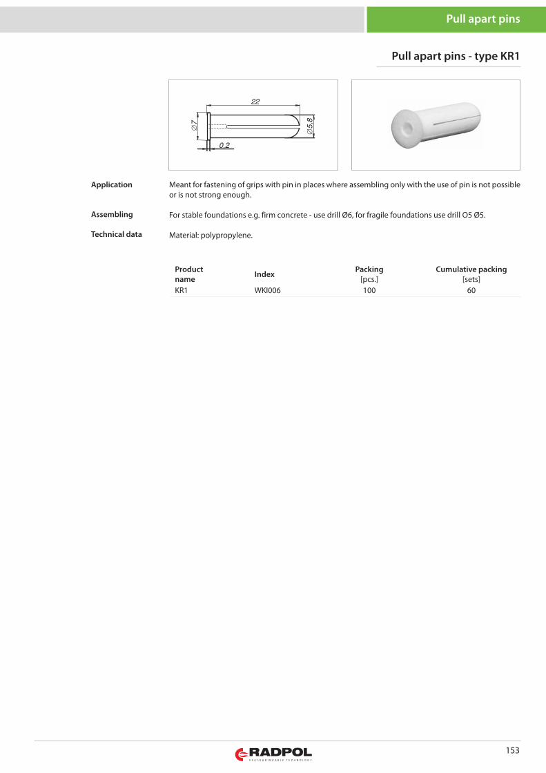
153
Pull apart pins
Productname Index Packing
[pcs.]Cumulative packing
[sets]KR1 WKI006 100 60
Pull apart pins - type KR1
Meant for fastening of grips with pin in places where assembling only with the use of pin is not possibleor is not strong enough.
For stable foundations e.g. firm concrete - use drill Ø6, for fragile foundations use drill O5 Ø5.
Material: polypropylene.
Application
Assembling
Technical data
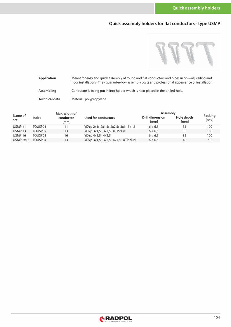
154
Quick assembly holders
Name ofset Index
Max. width ofconductor
[mm]Used for conductors
AssemblyPacking
[pcs.]Drill dimension
[mm]Hole depth
[mm]USMP 11 TOUSP01 11 YDYp 2x1; 2x1,5; 2x2,5; 3x1; 3x1,5 6 ÷ 6,5 35 100USMP 13 TOUSP02 13 YDYp 3x1,5; 3x2,5; UTP-dual 6 ÷ 6,5 35 100USMP 16 TOUSP03 16 YDYp 4x1,5; 4x2,5 6 ÷ 6,5 35 100USMP 2x13 TOUSP04 13 YDYp 3x1,5; 3x2,5; 4x1,5; UTP-dual 6 ÷ 6,5 40 50
Quick assembly holders for flat conductors - type USMP
Meant for easy and quick assembly of round and flat conductors and pipes in on-wall, ceiling andfloor installations. They guarantee low assembly costs and professional appearance of installation.
Conductor is being put in into holder which is next placed in the drilled-hole.
Material: polypropylene.
Application
Assembling
Technical data
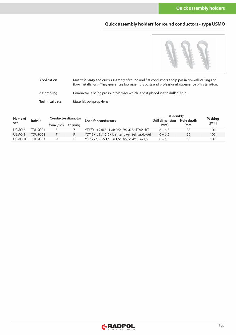
155
Quick assembly holders
Name ofset Indeks
Conductor diameterUsed for conductors
AssemblyPacking
[pcs.]Drill dimension
[mm]Hole depth
[mm]from [mm] to [mm]USMO 6 TOUSO01 5 7 YTKSY 1x2x0,5; 1x4x0,5; 5x2x0,5; DY6; UYP 6 ÷ 6,5 35 100USMO 8 TOUSO02 7 9 YDY 2x1; 2x1,5; 3x1; antenowe i tel. kablowej 6 ÷ 6,5 35 100USMO 10 TOUSO03 9 11 YDY 2x2,5; 2x1,5; 3x1,5; 3x2,5; 4x1; 4x1,5 6 ÷ 6,5 35 100
Quick assembly holders for round conductors - type USMO
Meant for easy and quick assembly of round and flat conductors and pipes in on-wall, ceiling andfloor installations. They guarantee low assembly costs and professional appearance of installation.
Conductor is being put in into holder which is next placed in the drilled-hole.
Material: polypropylene.
Application
Assembling
Technical data
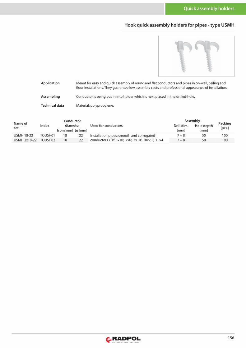
156
Quick assembly holders
Name of set Index
Conductordiameter Used for conductors
AssemblyPacking
[pcs.]Drill dim.[mm]
Hole depth[mm]from[mm] to [mm]
USMH 18-22 TOUSH01 18 22 Installation pipes: smooth and corrugatedconductors YDY 5x10; 7x6; 7x10; 10x2,5; 10x4
7 ÷ 8 50 100USMH 2x18-22 TOUSH02 18 22 7 ÷ 8 50 100
Hook quick assembly holders for pipes - type USMH
Meant for easy and quick assembly of round and flat conductors and pipes in on-wall, ceiling andfloor installations. They guarantee low assembly costs and professional appearance of installation.
Conductor is being put in into holder which is next placed in the drilled-hole.
Material: polypropylene.
Application
Assembling
Technical data
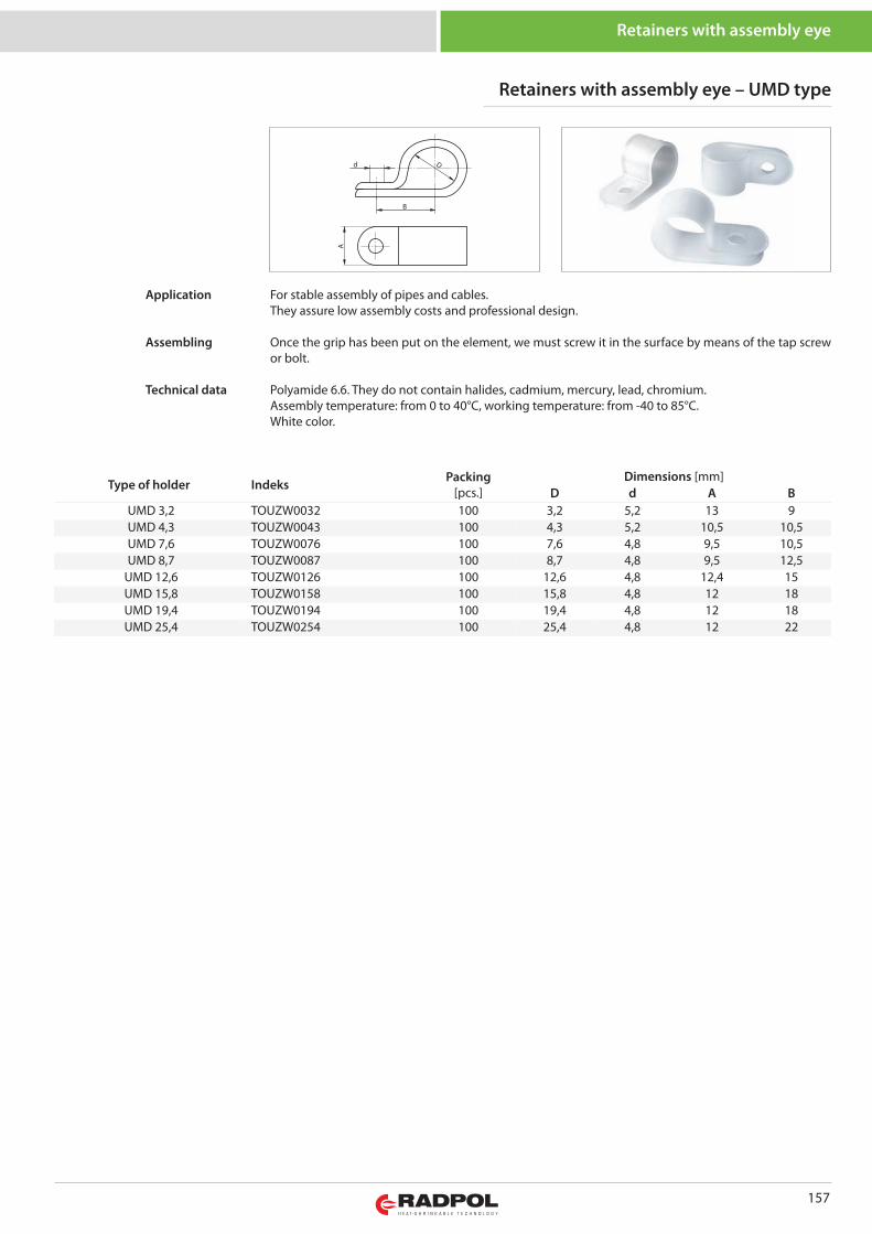
157
Retainers with assembly eye
Type of holder Indeks Packing[pcs.]
Dimensions [mm]D d A B
UMD 3,2 TOUZW0032 100 3,2 5,2 13 9UMD 4,3 TOUZW0043 100 4,3 5,2 10,5 10,5UMD 7,6 TOUZW0076 100 7,6 4,8 9,5 10,5UMD 8,7 TOUZW0087 100 8,7 4,8 9,5 12,5
UMD 12,6 TOUZW0126 100 12,6 4,8 12,4 15UMD 15,8 TOUZW0158 100 15,8 4,8 12 18UMD 19,4 TOUZW0194 100 19,4 4,8 12 18UMD 25,4 TOUZW0254 100 25,4 4,8 12 22
B
d D
A
Retainers with assembly eye – UMD type
For stable assembly of pipes and cables.They assure low assembly costs and professional design.
Once the grip has been put on the element, we must screw it in the surface by means of the tap screwor bolt.
Polyamide 6.6. They do not contain halides, cadmium, mercury, lead, chromium.Assembly temperature: from 0 to 40°C, working temperature: from -40 to 85°C.White color.
Application
Assembling
Technical data
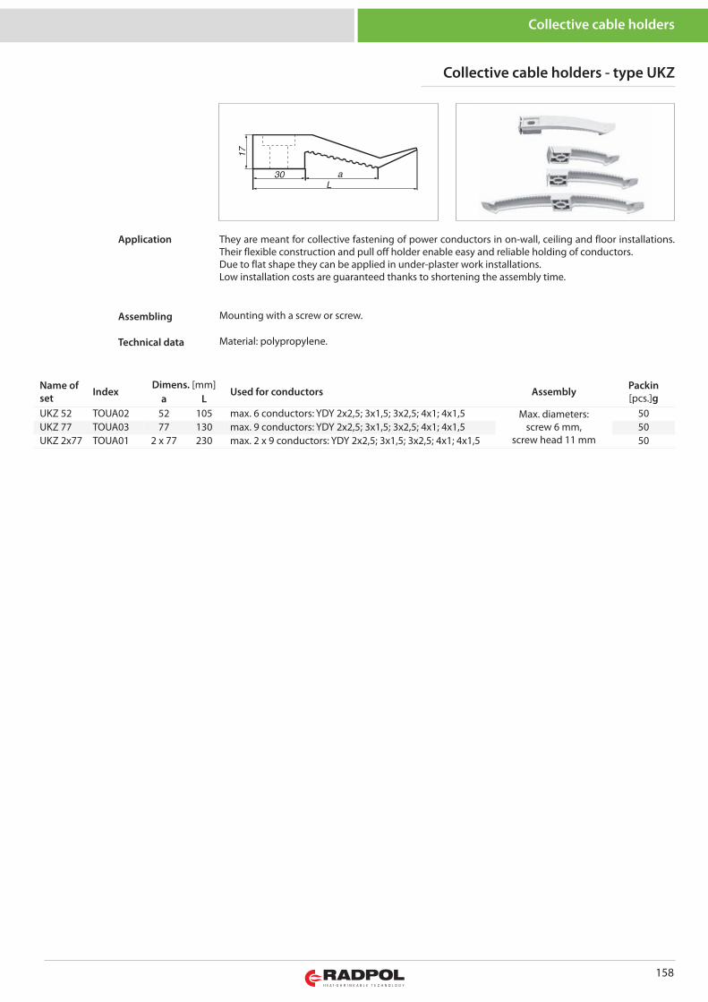
158
Collective cable holders
Collective cable holders - type UKZ
Name ofset Index
Dimens. [mm]Used for conductors Assembly Packin
[pcs.]ga LUKZ 52 TOUA02 52 105 max. 6 conductors: YDY 2x2,5; 3x1,5; 3x2,5; 4x1; 4x1,5 Max. diameters:
screw 6 mm,screw head 11 mm
50UKZ 77 TOUA03 77 130 max. 9 conductors: YDY 2x2,5; 3x1,5; 3x2,5; 4x1; 4x1,5 50UKZ 2x77 TOUA01 2 x 77 230 max. 2 x 9 conductors: YDY 2x2,5; 3x1,5; 3x2,5; 4x1; 4x1,5 50
They are meant for collective fastening of power conductors in on-wall, ceiling and floor installations.Their flexible construction and pull off holder enable easy and reliable holding of conductors.Due to flat shape they can be applied in under-plaster work installations.Low installation costs are guaranteed thanks to shortening the assembly time.
Mounting with a screw or screw.
Material: polypropylene.
Application
Assembling
Technical data
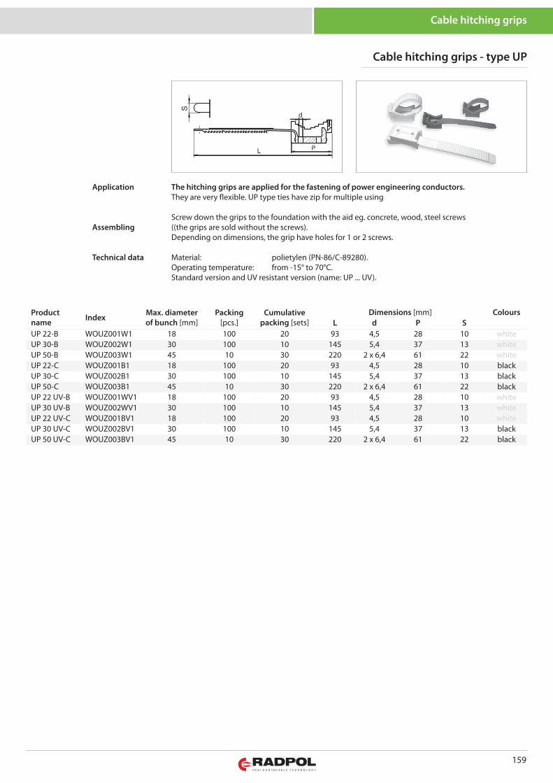
159
Cable hitching grips - type UP
Productname Index Max. diameter
of bunch [mm]Packing
[pcs.]Cumulative
packing [sets]Dimensions [mm] Colours
L d P SUP 22-B WOUZ001W1 18 100 20 93 4,5 28 10 whiteUP 30-B WOUZ002W1 30 100 10 145 5,4 37 13 whiteUP 50-B WOUZ003W1 45 10 30 220 2 x 6,4 61 22 whiteUP 22-C WOUZ001B1 18 100 20 93 4,5 28 10 blackUP 30-C WOUZ002B1 30 100 10 145 5,4 37 13 blackUP 50-C WOUZ003B1 45 10 30 220 2 x 6,4 61 22 blackUP 22 UV-B WOUZ001WV1 18 100 20 93 4,5 28 10 whiteUP 30 UV-B WOUZ002WV1 30 100 10 145 5,4 37 13 whiteUP 22 UV-C WOUZ001BV1 18 100 20 93 4,5 28 10 whiteUP 30 UV-C WOUZ002BV1 30 100 10 145 5,4 37 13 blackUP 50 UV-C WOUZ003BV1 45 10 30 220 2 x 6,4 61 22 black
Cable hitching grips
The hitching grips are applied for the fastening of power engineering conductors. They are very flexible. UP type ties have zip for multiple using
Screw down the grips to the foundation with the aid eg. concrete, wood, steel screws((the grips are sold without the screws).Depending on dimensions, the grip have holes for 1 or 2 screws.
Material: polietylen (PN-86/C-89280). Operating temperature: from -15° to 70°C.Standard version and UV resistant version (name: UP ... UV).
Application
Assembling
Technical data
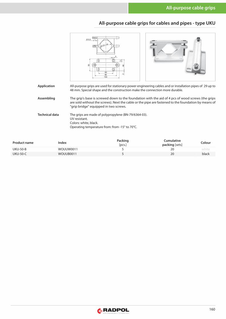
160
All-purpose cable grips
All-purpose cable grips for cables and pipes - type UKU
Product name Index Packing[pcs.]
Cumulativepacking [sets] Colour
UKU-50-B WOUUW0011 5 20 whiteUKU-50-C WOUUB0011 5 20 black
All-purpose grips are used for stationary power engineering cables and or installation pipes of 29 up to48 mm. Special shape and the construction make the connection more durable.
The grip's base is screwed down to the foundation with the aid of 4 pcs of wood screws (the gripsare sold without the screws). Next the cable or the pipe are fastened to the foundation by means of"grip bridge" equipped in two screws.
The grips are made of polypropylene (BN-79/6364-03).UV resistant.Colors: white, black.Operating temperature from: from -15° to 70°C.
Application
Assembling
Technical data
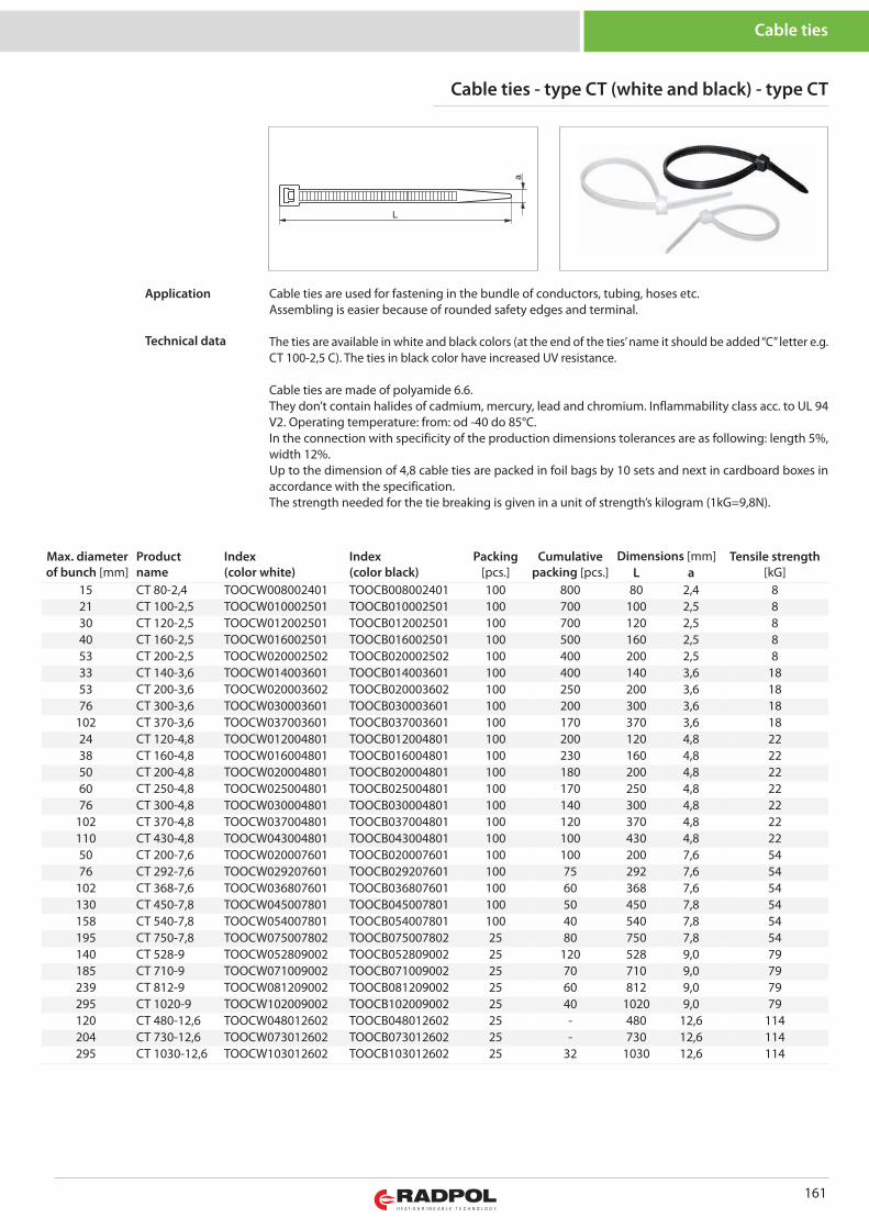
161
Cable ties
Max. diameterof bunch [mm]
Productname
Index(color white)
Index(color black)
Packing[pcs.]
Cumulativepacking [pcs.]
Dimensions [mm] Tensile strength[kG]L a
15 CT 80-2,4 TOOCW008002401 TOOCB008002401 100 800 80 2,4 821 CT 100-2,5 TOOCW010002501 TOOCB010002501 100 700 100 2,5 830 CT 120-2,5 TOOCW012002501 TOOCB012002501 100 700 120 2,5 840 CT 160-2,5 TOOCW016002501 TOOCB016002501 100 500 160 2,5 853 CT 200-2,5 TOOCW020002502 TOOCB020002502 100 400 200 2,5 833 CT 140-3,6 TOOCW014003601 TOOCB014003601 100 400 140 3,6 1853 CT 200-3,6 TOOCW020003602 TOOCB020003602 100 250 200 3,6 1876 CT 300-3,6 TOOCW030003601 TOOCB030003601 100 200 300 3,6 18
102 CT 370-3,6 TOOCW037003601 TOOCB037003601 100 170 370 3,6 1824 CT 120-4,8 TOOCW012004801 TOOCB012004801 100 200 120 4,8 2238 CT 160-4,8 TOOCW016004801 TOOCB016004801 100 230 160 4,8 2250 CT 200-4,8 TOOCW020004801 TOOCB020004801 100 180 200 4,8 2260 CT 250-4,8 TOOCW025004801 TOOCB025004801 100 170 250 4,8 2276 CT 300-4,8 TOOCW030004801 TOOCB030004801 100 140 300 4,8 22
102 CT 370-4,8 TOOCW037004801 TOOCB037004801 100 120 370 4,8 22110 CT 430-4,8 TOOCW043004801 TOOCB043004801 100 100 430 4,8 2250 CT 200-7,6 TOOCW020007601 TOOCB020007601 100 100 200 7,6 5476 CT 292-7,6 TOOCW029207601 TOOCB029207601 100 75 292 7,6 54
102 CT 368-7,6 TOOCW036807601 TOOCB036807601 100 60 368 7,6 54130 CT 450-7,8 TOOCW045007801 TOOCB045007801 100 50 450 7,8 54158 CT 540-7,8 TOOCW054007801 TOOCB054007801 100 40 540 7,8 54195 CT 750-7,8 TOOCW075007802 TOOCB075007802 25 80 750 7,8 54140 CT 528-9 TOOCW052809002 TOOCB052809002 25 120 528 9,0 79185 CT 710-9 TOOCW071009002 TOOCB071009002 25 70 710 9,0 79239 CT 812-9 TOOCW081209002 TOOCB081209002 25 60 812 9,0 79295 CT 1020-9 TOOCW102009002 TOOCB102009002 25 40 1020 9,0 79120 CT 480-12,6 TOOCW048012602 TOOCB048012602 25 - 480 12,6 114204 CT 730-12,6 TOOCW073012602 TOOCB073012602 25 - 730 12,6 114295 CT 1030-12,6 TOOCW103012602 TOOCB103012602 25 32 1030 12,6 114
Cable ties - type CT (white and black) - type CT
Cable ties are used for fastening in the bundle of conductors, tubing, hoses etc.Assembling is easier because of rounded safety edges and terminal.
The ties are available in white and black colors (at the end of the ties’ name it should be added “C” letter e.g.CT 100-2,5 C). The ties in black color have increased UV resistance.
Cable ties are made of polyamide 6.6. They don’t contain halides of cadmium, mercury, lead and chromium. Inflammability class acc. to UL 94V2. Operating temperature: from: od -40 do 85°C.In the connection with specificity of the production dimensions tolerances are as following: length 5%,width 12%. Up to the dimension of 4,8 cable ties are packed in foil bags by 10 sets and next in cardboard boxes inaccordance with the specification. The strength needed for the tie breaking is given in a unit of strength’s kilogram (1kG=9,8N).
Application
Technical data
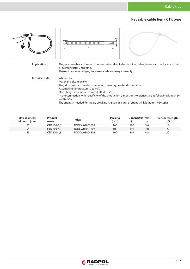
162
Cable ties
Reusable cable ties – CTK type
Max. diameterof bunch [mm]
Productname Index Packing
[pcs.]Dimensions [mm] Tensile strength
[kG]L a25 CTK 100-3,6 TOOCW01003602 100 100 3,6 1854 CTK 200-4,8 TOOCW02004802 100 198 4,8 2285 CTK 300-4,8 TOOCW03004802 100 301 4,8 22
They are reusable and serve to connect a bundle of electric wires, tubes, hoses etc. thanks to a zip witha lever for easier unzipping.Thanks to rounded edges, they assure safe and easy assembly.
White color.Material: polyamide 6.6.They don’t contain halides of cadmium, mercury, lead and chromium. Assembling temperature: 0 to 40°C. Operating temperature: from: od -40 do 85°C. In the connection with specificity of the production dimensions tolerances are as following: length 5%,width 12%.The strength needed for the tie breaking is given in a unit of strength’s kilogram (1kG=9,8N).
Application
Technical data
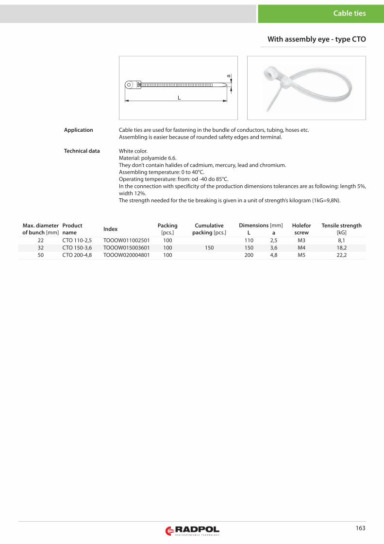
163
Cable ties
With assembly eye - type CTO
Max. diameterof bunch [mm]
Productname Index Packing
[pcs.]Cumulative
packing [pcs.]Dimensions [mm] Holefor
screwTensile strength
[kG]L a22 CTO 110-2,5 TOOOW011002501 100 110 2,5 M3 8,132 CTO 150-3,6 TOOOW015003601 100 150 150 3,6 M4 18,250 CTO 200-4,8 TOOOW020004801 100 200 4,8 M5 22,2
Cable ties are used for fastening in the bundle of conductors, tubing, hoses etc.Assembling is easier because of rounded safety edges and terminal.
White color.Material: polyamide 6.6.They don’t contain halides of cadmium, mercury, lead and chromium. Assembling temperature: 0 to 40°C. Operating temperature: from: od -40 do 85°C. In the connection with specificity of the production dimensions tolerances are as following: length 5%,width 12%.The strength needed for the tie breaking is given in a unit of strength’s kilogram (1kG=9,8N).
Application
Technical data
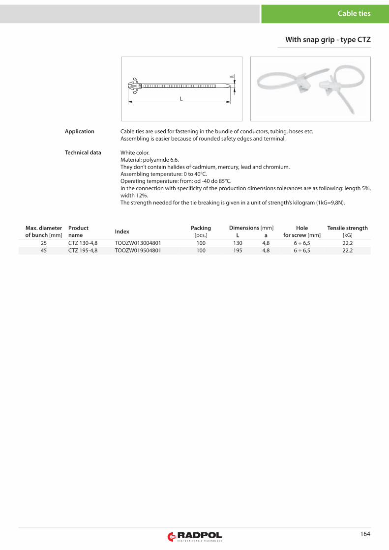
164
Cable ties
With snap grip - type CTZ
Cable ties are used for fastening in the bundle of conductors, tubing, hoses etc.Assembling is easier because of rounded safety edges and terminal.
White color.Material: polyamide 6.6.They don’t contain halides of cadmium, mercury, lead and chromium. Assembling temperature: 0 to 40°C. Operating temperature: from: od -40 do 85°C. In the connection with specificity of the production dimensions tolerances are as following: length 5%,width 12%.The strength needed for the tie breaking is given in a unit of strength’s kilogram (1kG=9,8N).
Application
Technical data
Max. diameterof bunch [mm]
Productname Index Packing
[pcs.]Dimensions [mm] Hole
for screw [mm]Tensile strength
[kG]L a25 CTZ 130-4,8 TOOZW013004801 100 130 4,8 6 ÷ 6,5 22,245 CTZ 195-4,8 TOOZW019504801 100 195 4,8 6 ÷ 6,5 22,2
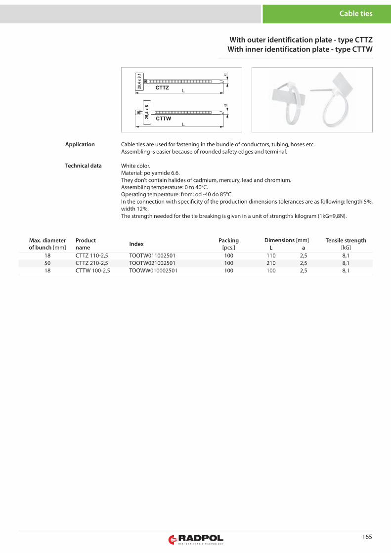
165
Cable ties
With outer identification plate - type CTTZWith inner identification plate - type CTTW
Max. diameterof bunch [mm]
Productname Index Packing
[pcs.]Dimensions [mm] Tensile strength
[kG]L a18 CTTZ 110-2,5 TOOTW011002501 100 110 2,5 8,150 CTTZ 210-2,5 TOOTW021002501 100 210 2,5 8,118 CTTW 100-2,5 TOOWW010002501 100 100 2,5 8,1
Cable ties are used for fastening in the bundle of conductors, tubing, hoses etc.Assembling is easier because of rounded safety edges and terminal.
White color.Material: polyamide 6.6.They don’t contain halides of cadmium, mercury, lead and chromium. Assembling temperature: 0 to 40°C. Operating temperature: from: od -40 do 85°C. In the connection with specificity of the production dimensions tolerances are as following: length 5%,width 12%.The strength needed for the tie breaking is given in a unit of strength’s kilogram (1kG=9,8N).
Application
Technical data
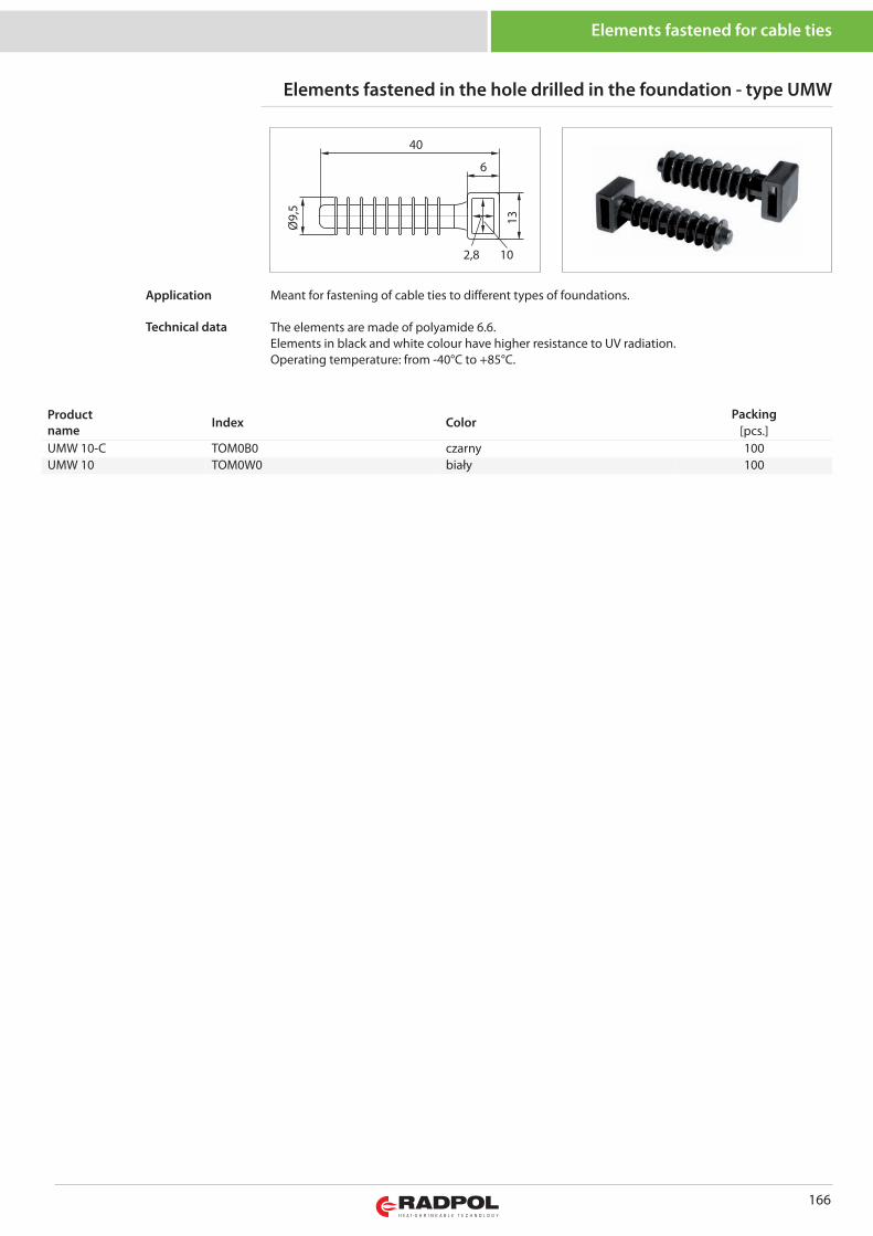
166
Elements fastened for cable ties
Elements fastened in the hole drilled in the foundation - type UMW
Productname Index Color
Packing[pcs.]
UMW 10-C TOM0B0 czarny 100UMW 10 TOM0W0 biały 100
102,8
6
40
Ø9,5
13
Meant for fastening of cable ties to different types of foundations.
The elements are made of polyamide 6.6. Elements in black and white colour have higher resistance to UV radiation. Operating temperature: from -40°C to +85°C.
Application
Technical data
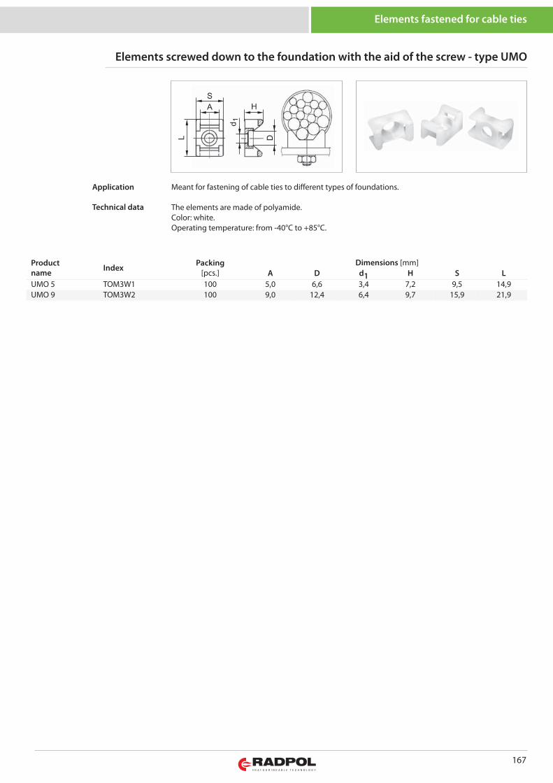
167
Elements fastened for cable ties
Elements screwed down to the foundation with the aid of the screw - type UMO
Productname Index Packing
[pcs.]Dimensions [mm]
A D d1 H S LUMO 5 TOM3W1 100 5,0 6,6 3,4 7,2 9,5 14,9UMO 9 TOM3W2 100 9,0 12,4 6,4 9,7 15,9 21,9
Meant for fastening of cable ties to different types of foundations.
The elements are made of polyamide.Color: white.Operating temperature: from -40°C to +85°C.
Application
Technical data
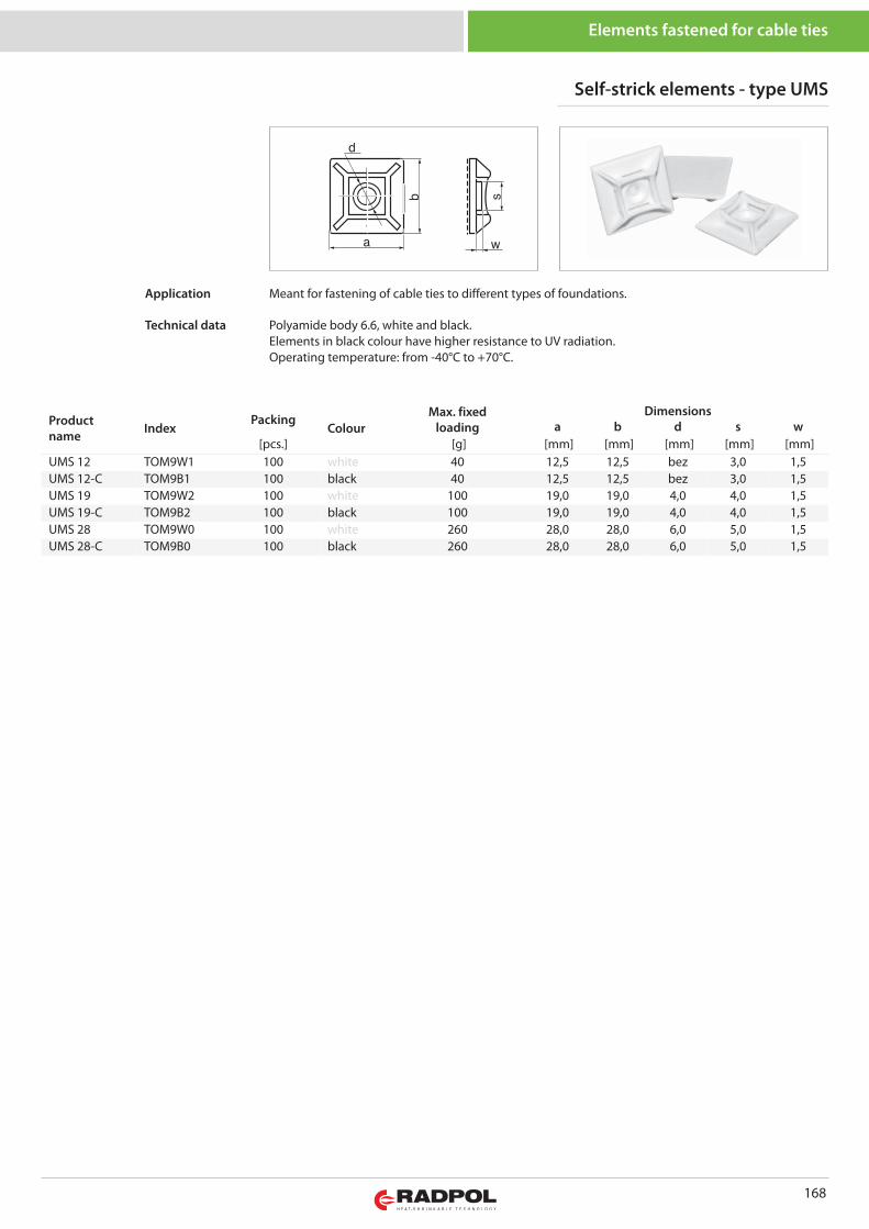
168
Elements fastened for cable ties
Productname Index
PackingColour
Max. fixedloading
Dimensionsa b d s w
[pcs.] [g] [mm] [mm] [mm] [mm] [mm]UMS 12 TOM9W1 100 white 40 12,5 12,5 bez 3,0 1,5UMS 12-C TOM9B1 100 black 40 12,5 12,5 bez 3,0 1,5UMS 19 TOM9W2 100 white 100 19,0 19,0 4,0 4,0 1,5UMS 19-C TOM9B2 100 black 100 19,0 19,0 4,0 4,0 1,5UMS 28 TOM9W0 100 white 260 28,0 28,0 6,0 5,0 1,5UMS 28-C TOM9B0 100 black 260 28,0 28,0 6,0 5,0 1,5
Self-strick elements - type UMS
Meant for fastening of cable ties to different types of foundations.
Polyamide body 6.6, white and black.Elements in black colour have higher resistance to UV radiation.Operating temperature: from -40°C to +70°C.
Application
Technical data
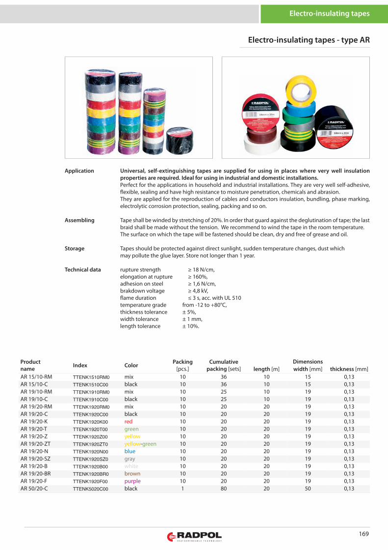
169
Electro-insulating tapes
Productname Index Color Packing
[pcs.]Cumulative
packing [sets]Dimensions
length [m] width [mm] thickness [mm]AR 15/10-RM TTENK1510RM0 mix 10 36 10 15 0,13AR 15/10-C TTENK1510C00 black 10 36 10 15 0,13AR 19/10-RM TTENK1910RM0 mix 10 25 10 19 0,13AR 19/10-C TTENK1910C00 black 10 25 10 19 0,13AR 19/20-RM TTENK1920RM0 mix 10 20 20 19 0,13AR 19/20-C TTENK1920C00 black 10 20 20 19 0,13AR 19/20-K TTENK1920K00 red 10 20 20 19 0,13AR 19/20-T TTENK1920T00 green 10 20 20 19 0,13AR 19/20-Z TTENK1920Z00 yellow 10 20 20 19 0,13AR 19/20-ZT TTENK1920ZT0 yellow-green 10 20 20 19 0,13AR 19/20-N TTENK1920N00 blue 10 20 20 19 0,13AR 19/20-SZ TTENK1920SZ0 gray 10 20 20 19 0,13AR 19/20-B TTENK1920B00 white 10 20 20 19 0,13AR 19/20-BR TTENK1920BR0 brown 10 20 20 19 0,13AR 19/20-F TTENK1920F00 purple 10 20 20 19 0,13AR 50/20-C TTENK5020C00 black 1 80 20 50 0,13
Electro-insulating tapes - type AR
Universal, self-extinguishing tapes are supplied for using in places where very well insulationproperties are required. Ideal for using in industrial and domestic installations.Perfect for the applications in household and industrial installations. They are very well self-adhesive,flexible, sealing and have high resistance to moisture penetration, chemicals and abrasion.They are applied for the reproduction of cables and conductors insulation, bundling, phase marking,electrolytic corrosion protection, sealing, packing and so on.
Tape shall be winded by stretching of 20%. In order that guard against the deglutination of tape; the lastbraid shall be made without the tension. We recommend to wind the tape in the room temperature.The surface on which the tape will be fastened should be clean, dry and free of grease and oil.
Tapes should be protected against direct sunlight, sudden temperature changes, dust whichmay pollute the glue layer. Store not longer than 1 year.
rupture strength ≥ 18 N/cm,elongation at rupture ≥ 160%,adhesion on steel ≥ 1,6 N/cm,brakdown voltage ≥ 4,8 kV,flame duration ≤ 3 s, acc. with UL 510temperature grade from -12 to +80°C,thickness tolerance ± 5%,width tolerance ± 1 mm,length tolerance ± 10%.
Application
Assembling
Storage
Technical data
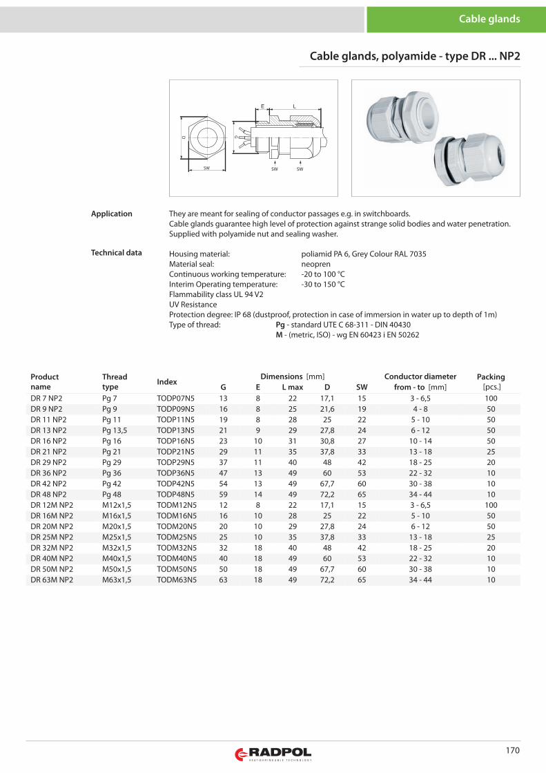
170
Cable glands
Cable glands, polyamide - type DR ... NP2
G
SW SW SW
Productname
Threadtype Index
Dimensions [mm] Conductor diameter Packing[pcs.]G E L max D SW from - to [mm]
DR 7 NP2 Pg 7 TODP07N5 13 8 22 17,1 15 3 - 6,5 100DR 9 NP2 Pg 9 TODP09N5 16 8 25 21,6 19 4 - 8 50DR 11 NP2 Pg 11 TODP11N5 19 8 28 25 22 5 - 10 50DR 13 NP2 Pg 13,5 TODP13N5 21 9 29 27,8 24 6 - 12 50DR 16 NP2 Pg 16 TODP16N5 23 10 31 30,8 27 10 - 14 50DR 21 NP2 Pg 21 TODP21N5 29 11 35 37,8 33 13 - 18 25DR 29 NP2 Pg 29 TODP29N5 37 11 40 48 42 18 - 25 20DR 36 NP2 Pg 36 TODP36N5 47 13 49 60 53 22 - 32 10DR 42 NP2 Pg 42 TODP42N5 54 13 49 67,7 60 30 - 38 10DR 48 NP2 Pg 48 TODP48N5 59 14 49 72,2 65 34 - 44 10DR 12M NP2 M12x1,5 TODM12N5 12 8 22 17,1 15 3 - 6,5 100DR 16M NP2 M16x1,5 TODM16N5 16 10 28 25 22 5 - 10 50DR 20M NP2 M20x1,5 TODM20N5 20 10 29 27,8 24 6 - 12 50DR 25M NP2 M25x1,5 TODM25N5 25 10 35 37,8 33 13 - 18 25DR 32M NP2 M32x1,5 TODM32N5 32 18 40 48 42 18 - 25 20DR 40M NP2 M40x1,5 TODM40N5 40 18 49 60 53 22 - 32 10DR 50M NP2 M50x1,5 TODM50N5 50 18 49 67,7 60 30 - 38 10DR 63M NP2 M63x1,5 TODM63N5 63 18 49 72,2 65 34 - 44 10
They are meant for sealing of conductor passages e.g. in switchboards.Cable glands guarantee high level of protection against strange solid bodies and water penetration.Supplied with polyamide nut and sealing washer.
Housing material: poliamid PA 6, Grey Colour RAL 7035Material seal: neoprenContinuous working temperature: -20 to 100 °CInterim Operating temperature: -30 to 150 °CFlammability class UL 94 V2UV ResistanceProtection degree: IP 68 (dustproof, protection in case of immersion in water up to depth of 1m)Type of thread: Pg - standard UTE C 68-311 - DIN 40430
M - (metric, ISO) - wg EN 60423 i EN 50262
Application
Technical data
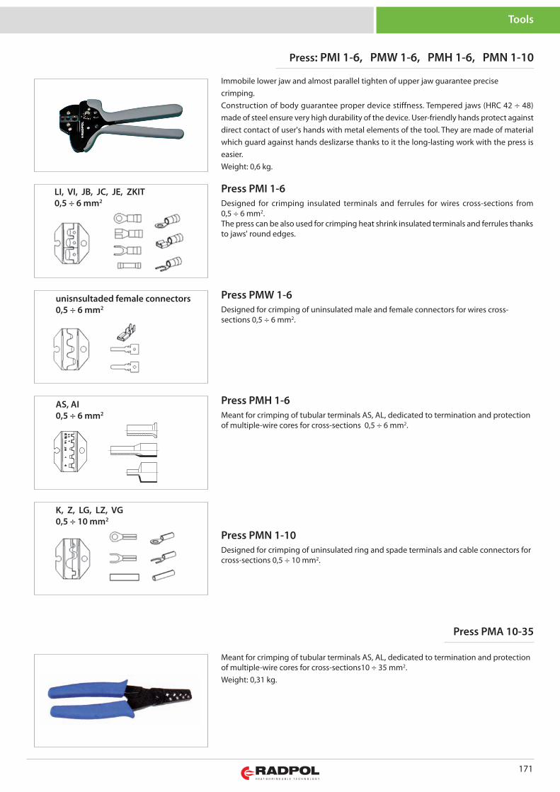
LI, VI, JB, JC, JE, ZKIT0,5 ÷ 6 mm2 Designed for crimping insulated terminals and ferrules for wires cross-sections from
0,5 ÷ 6 mm2.The press can be also used for crimping heat shrink insulated terminals and ferrules thanksto jaws' round edges.
Immobile lower jaw and almost parallel tighten of upper jaw guarantee precisecrimping.Construction of body guarantee proper device stiffness. Tempered jaws (HRC 42 ÷ 48)made of steel ensure very high durability of the device. User-friendly hands protect againstdirect contact of user's hands with metal elements of the tool. They are made of materialwhich guard against hands deslizarse thanks to it the long-lasting work with the press iseasier.Weight: 0,6 kg.
Press: PMI 1-6, PMW 1-6, PMH 1-6, PMN 1-10
Press PMA 10-35
Press PMI 1-6
Meant for crimping of tubular terminals AS, AL, dedicated to termination and protectionof multiple-wire cores for cross-sections10 ÷ 35 mm2.Weight: 0,31 kg.
Designed for crimping of uninsulated male and female connectors for wires cross-sections 0,5 ÷ 6 mm2.
Press PMW 1-6unisnsultaded female connectors0,5 ÷ 6 mm2
Meant for crimping of tubular terminals AS, AL, dedicated to termination and protectionof multiple-wire cores for cross-sections 0,5 ÷ 6 mm2.
Press PMH 1-6AS, AI0,5 ÷ 6 mm2
Designed for crimping of uninsulated ring and spade terminals and cable connectors forcross-sections 0,5 ÷ 10 mm2.
Press PMN 1-10
K, Z, LG, LZ, VG 0,5 ÷ 10 mm2
171
Tools
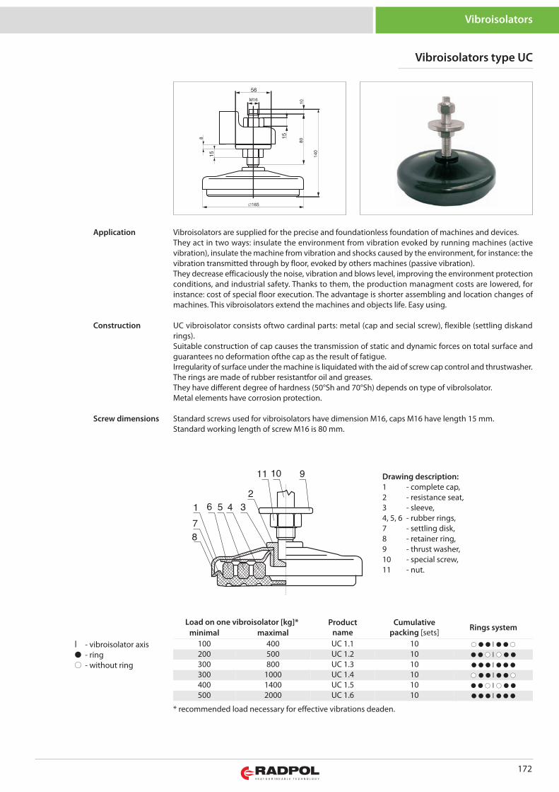
172
Vibroisolators
Vibroisolators type UC
Load on one vibroisolator [kg]* Productname
Cumulativepacking [sets] Rings system
minimal maximal100 400 UC 1.1 10 ● ● ● | ● ● ●
200 500 UC 1.2 10 ● ● ● | ● ● ●
300 800 UC 1.3 10 ● ● ● | ● ● ●
300 1000 UC 1.4 10 ● ● ● | ● ● ●
400 1400 UC 1.5 10 ● ● ● | ● ● ●
500 2000 UC 1.6 10 ● ● ● | ● ● ●
| - vibroisolator axis● - ring● - without ring
* recommended load necessary for effective vibrations deaden.
Drawing description:1 - complete cap,2 - resistance seat,3 - sleeve,4, 5, 6 - rubber rings,7 - settling disk,8 - retainer ring,9 - thrust washer,10 - special screw,11 - nut.
Vibroisolators are supplied for the precise and foundationless foundation of machines and devices. They act in two ways: insulate the environment from vibration evoked by running machines (activevibration), insulate the machine from vibration and shocks caused by the environment, for instance: thevibration transmitted through by floor, evoked by others machines (passive vibration).They decrease efficaciously the noise, vibration and blows level, improving the environment protectionconditions, and industrial safety. Thanks to them, the production managment costs are lowered, forinstance: cost of special floor execution. The advantage is shorter assembling and location changes ofmachines. This vibroisolators extend the machines and objects life. Easy using.
UC vibroisolator consists oftwo cardinal parts: metal (cap and secial screw), flexible (settling diskandrings).Suitable construction of cap causes the transmission of static and dynamic forces on total surface andguarantees no deformation ofthe cap as the result of fatigue.Irregularity of surface under the machine is liquidated with the aid of screw cap control and thrustwasher.The rings are made of rubber resistantfor oil and greases.They have different degree of hardness (50°Sh and 70°Sh) depends on type of vibrolsolator.Metal elements have corrosion protection.
Standard screws used for vibroisolators have dimension M16, caps M16 have length 15 mm.Standard working length of screw M16 is 80 mm.
Application
Construction
Screw dimensions

RADPOL S.A. ul. Batorego 14, 77-300 Człuchów, Poland I +48 59 834 22 71 I [email protected] I www.radpol.com.pl