heat transfer/heat exchanger
DESCRIPTION
Heat Transfer/Heat Exchanger. How is the heat transfer? Mechanism of Convection Applications . Mean fluid Velocity and Boundary and their effect on the rate of heat transfer. Fundamental equation of heat transfer Logarithmic-mean temperature difference. Heat transfer Coefficients. - PowerPoint PPT PresentationTRANSCRIPT
Heat Transfer/Heat Exchanger• How is the heat transfer? • Mechanism of Convection• Applications . • Mean fluid Velocity and Boundary and their effect on the rate of heat
transfer.• Fundamental equation of heat transfer• Logarithmic-mean temperature difference.• Heat transfer Coefficients.• Heat flux and Nusselt correlation • Simulation program for Heat Exchanger
How is the heat transfer?
• Heat can transfer between the surface of a solid conductor and the surrounding medium whenever temperature gradient exists.ConductionConvection
Natural convection Forced Convection
Natural and forced Convection
Natural convection occurs whenever heat flows between a solid and fluid, or between fluid layers.
As a result of heat exchange
Change in density of effective fluid layers taken place, which causes upward flow of heated fluid.
If this motion is associated with heat transfer mechanism only, then it is called Natural Convection
Forced Convection
If this motion is associated by mechanical means such as pumps, gravity or fans, the movement of the fluid is enforced.
And in this case, we then speak of Forced convection.
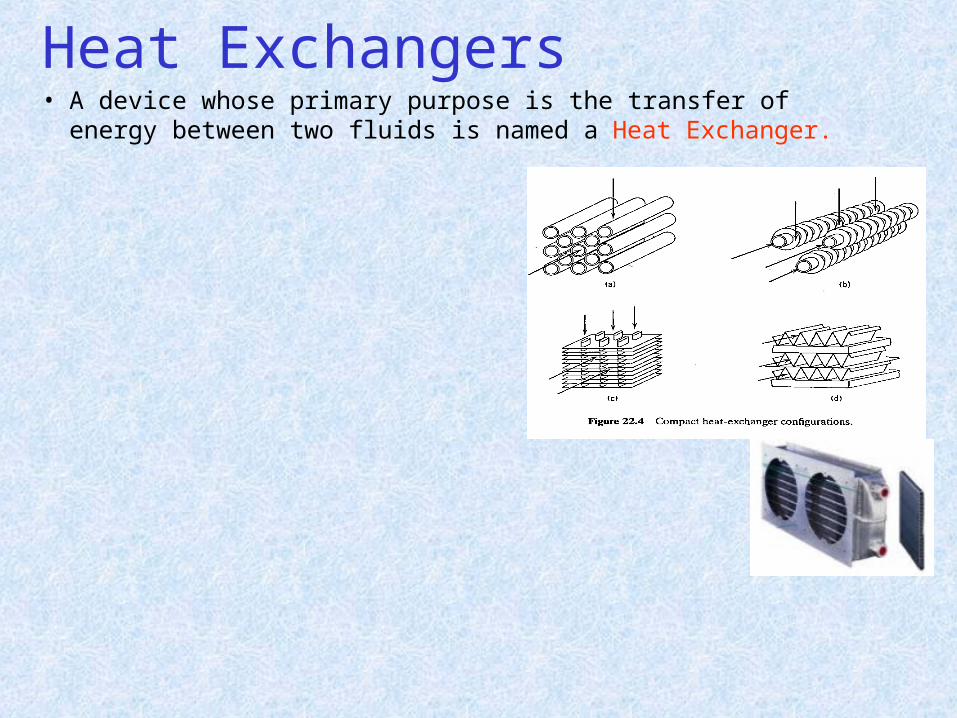
Heat Exchangers• A device whose primary purpose is the transfer of energy
between two fluids is named a Heat Exchanger.
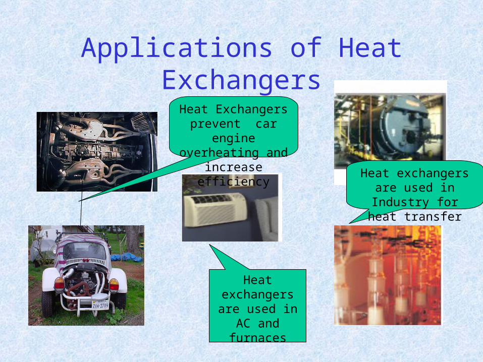
Applications of Heat Exchangers
Heat Exchangers prevent car engine
overheating and increase efficiency
Heat exchangers are used in Industry for
heat transfer
Heat exchangers are used in AC and
furnaces
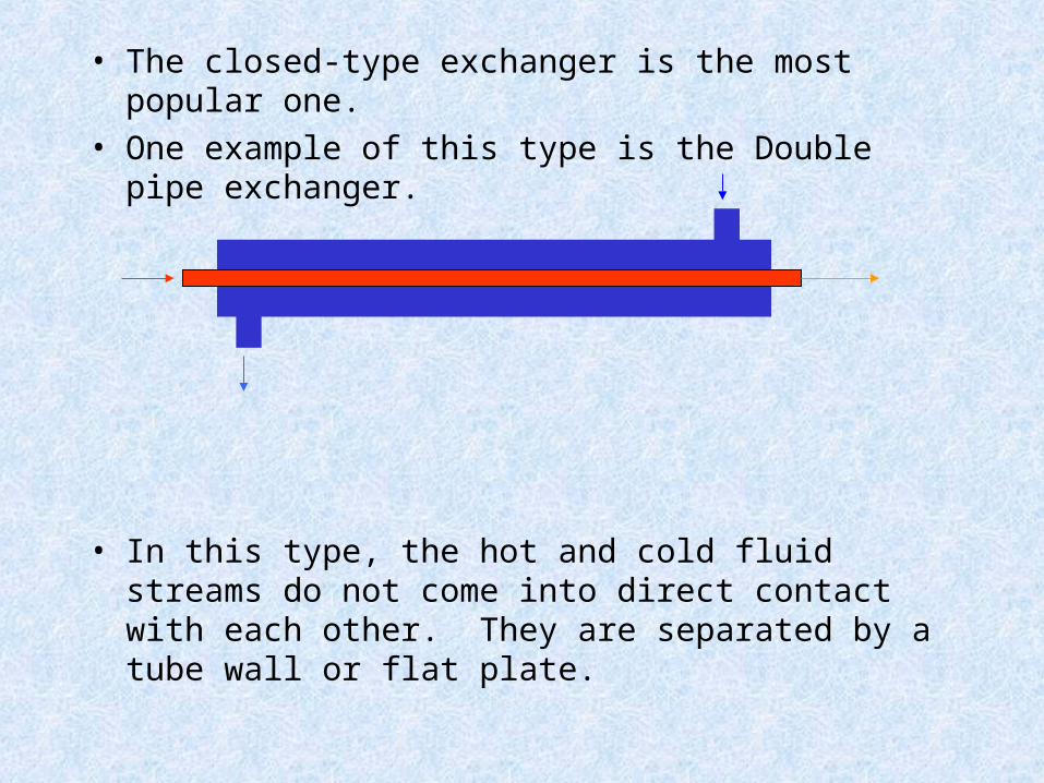
• The closed-type exchanger is the most popular one.
• One example of this type is the Double pipe exchanger.
• In this type, the hot and cold fluid streams do not come into direct contact with each other. They are separated by a tube wall or flat plate.
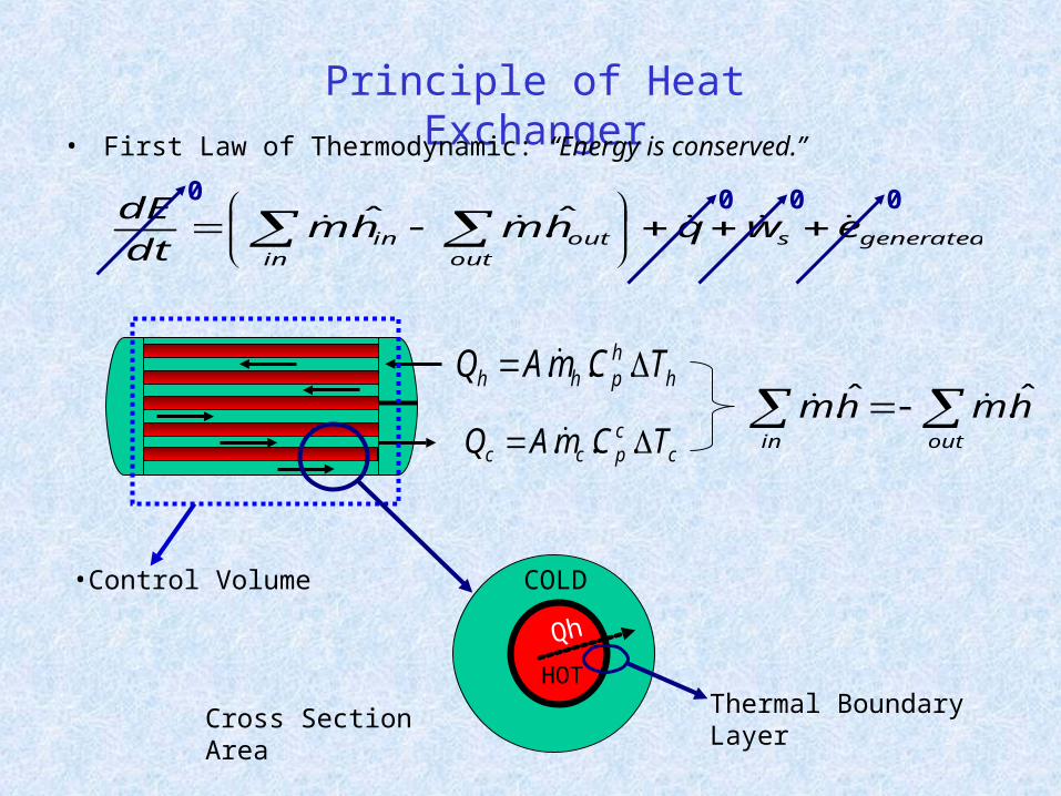
Principle of Heat Exchanger• First Law of Thermodynamic: “Energy is conserved.”
generatedsin out
outin ewqhmhmdt
dE
ˆ.ˆ.
outin
hmhm ˆ.ˆ. h
hphh TCmAQ ...
ccpcc TCmAQ ...
0 0 0 0
•Control Volume
Qh
Cross Section Area
HOT
COLD
Thermal Boundary Layer
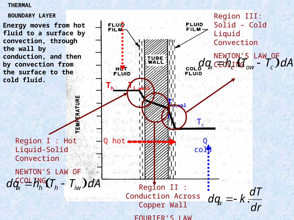
Q hot Q cold
Th Ti,wall
To,wall
Tc
Region I : Hot Liquid-Solid Convection
NEWTON’S LAW OF CCOLING
dqx hh . Th Tiw .dA Region II : Conduction Across Copper Wall
FOURIER’S LAW
dqx k.dT
dr
Region III: Solid – Cold Liquid Convection
NEWTON’S LAW OF CCOLING
dqx hc . Tow Tc .dA
THERMAL
BOUNDARY LAYER
Energy moves from hot fluid to a surface by convection, through the wall by conduction, and then by convection from the surface to the cold fluid.
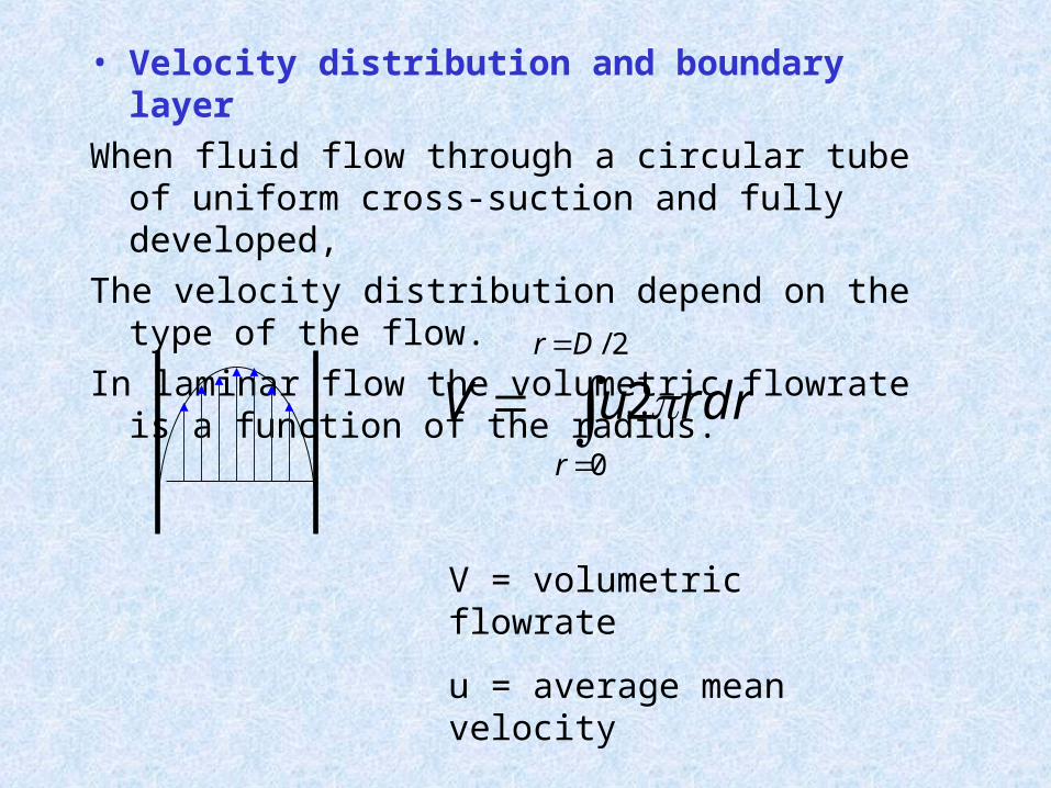
• Velocity distribution and boundary layer
When fluid flow through a circular tube of uniform cross-suction and fully developed,
The velocity distribution depend on the type of the flow.
In laminar flow the volumetric flowrate is a function of the radius.
V u2rdrr0
rD / 2
V = volumetric flowrate
u = average mean velocity
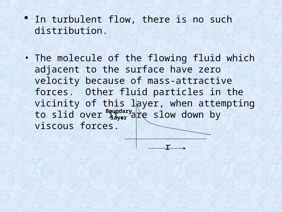
In turbulent flow, there is no such distribution.
• The molecule of the flowing fluid which adjacent to the surface have zero velocity because of mass-attractive forces. Other fluid particles in the vicinity of this layer, when attempting to slid over it, are slow down by viscous forces.
r
Boundary layer
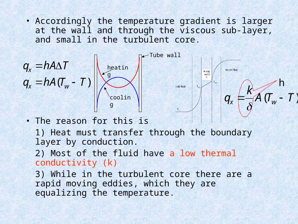
• Accordingly the temperature gradient is larger at the wall and through the viscous sub-layer, and small in the turbulent core.
• The reason for this is 1) Heat must transfer through the boundary layer by conduction.2) Most of the fluid have a low thermal conductivity (k)3) While in the turbulent core there are a rapid moving eddies, which they are equalizing the temperature.
heating
cooling
Tube wall
Twh
Twc
Tc
Metalwall
Warm fluid
cold fluid
qx hAT
qx hA(Tw T)
qx k
A(Tw T)
h
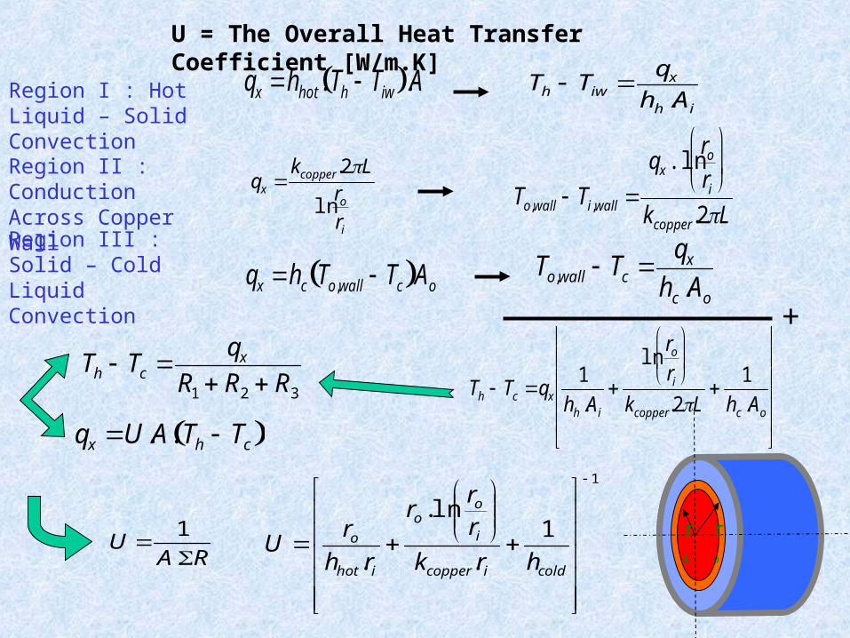
Region I : Hot Liquid – Solid Convection
Th Tiw qx
hh .Ai
qx hhot . Th Tiw .A
Region II : Conduction Across Copper Wall
qx kcopper .2L
lnro
ri
To,wall Ti,wall qx .ln
ro
ri
kcopper .2L
Region III : Solid – Cold Liquid Convection
To,wall Tc qx
hc .Ao
qx hc To,wall Tc Ao
+
Th Tc qx
1
hh .Ai
ln
ro
ri
kcopper .2L
1
hc .Ao
qx U.A. Th Tc 1
1
.
ln.
.
coldicopper
i
oo
ihot
o
hrk
rr
r
rh
rU
U = The Overall Heat Transfer Coefficient [W/m.K]
Th Tc qx
R1 R2 R3
U 1
A.R
r
o
r
i
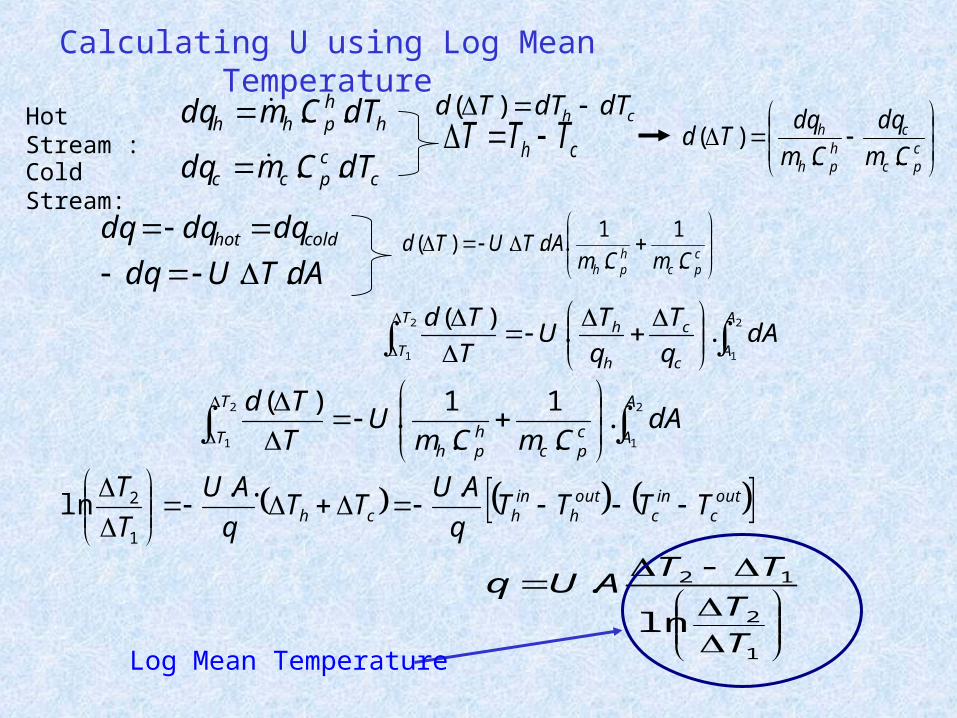
Calculating U using Log Mean Temperature
coldhot dqdqdq
ch TTT ch dTdTTd )(
hhphh dTCmdq ..
ccpcc dTCmdq ..
Hot Stream :
Cold Stream:
cpc
chph
h
Cm
dq
Cm
dqTd
..)(
dATUdq ..
cpc
hph CmCm
dATUTd.
1
.
1...)(
2
1
2
1
..
1
.
1.
)( A
Acpc
hph
T
TdA
CmCmU
T
Td
outc
inc
outh
inhch TTTT
q
AUTT
q
AU
T
T
...
ln1
2
2
1
2
1
..)( A
Ac
c
h
hT
TdA
q
T
q
TU
T
Td
1
2
12
ln
.
TT
TTAUq
Log Mean Temperature
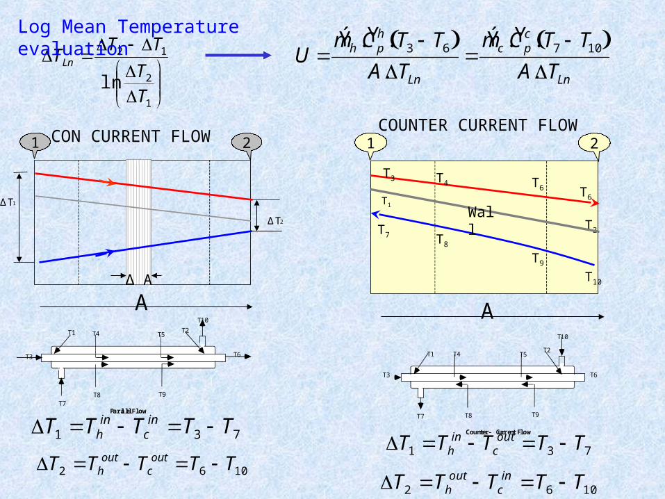
CON CURRENT FLOW
1
2
12
lnT
T
TTTLn
731 TTTTT inc
inh
1062 TTTTT outc
outh
COUNTER CURRENT FLOW
1062 TTTTT inc
outh
731 TTTTT outc
inh
U Ý m h . Ý C p
h . T3 T6 A.TLn
Ý m c . Ý C p
c . T7 T10 A.TLn
T1T2
T4 T5
T3
T7 T8 T9
T10
T6
Counter - Current Flow
T1 T2T4 T5
T6T3
T7T8 T9
T10
Parallel Flow
Log Mean Temperature evaluation
T1
A
1 2
T2
T3
T6
T4 T6
T7 T8
T9
T10
Wall∆ T1
∆ T2
∆ A
A
1 2
T1
A
1 2
T2
T3
T6
T4 T6
T7 T8
T9
T10
Wall
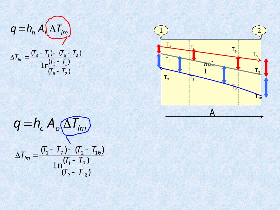
q hh Ai Tlm
Tlm (T3 T1) (T6 T2)
ln(T3 T1)
(T6 T2)
q hc Ao Tlm
Tlm (T1 T7) (T2 T10)
ln(T1 T7)
(T2 T10)
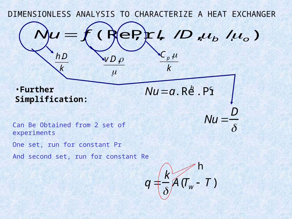
Nu f (Re,Pr,L /D,b /o)
DIMENSIONLESS ANALYSIS TO CHARACTERIZE A HEAT EXCHANGER
..Dv
k
C p .k
Dh.
Nu a.Reb .Pr c•Further Simplification:
Can Be Obtained from 2 set of experiments
One set, run for constant Pr
And second set, run for constant Re
q k
A(Tw T )
h
Nu D
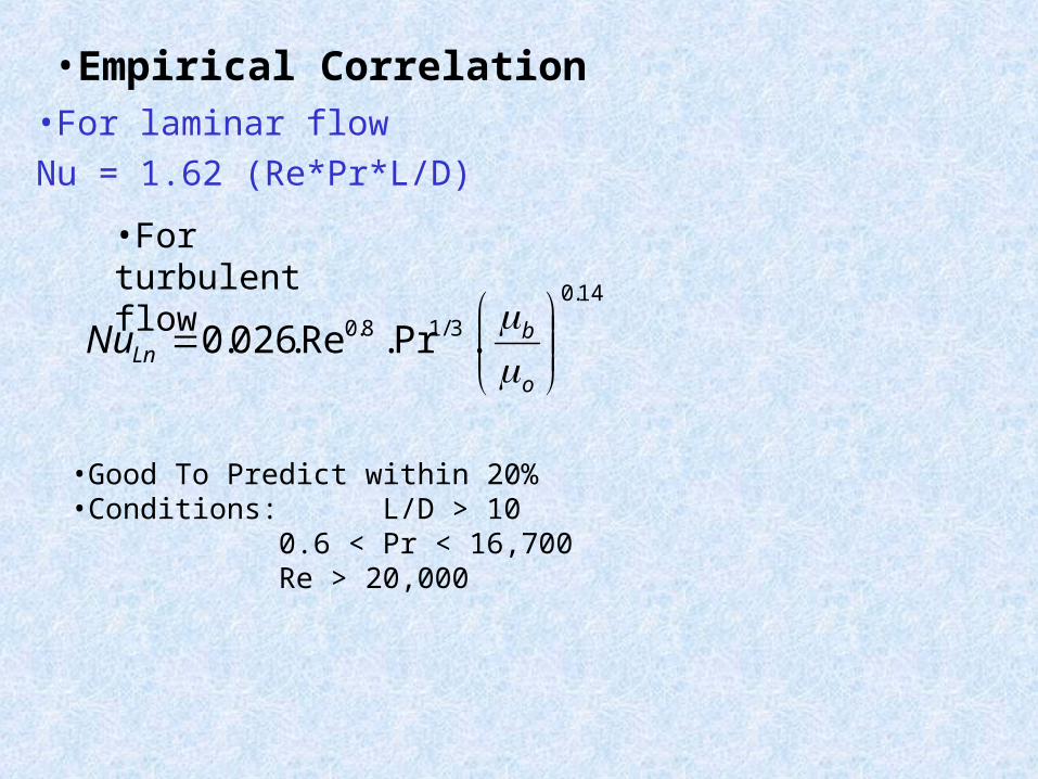
•For laminar flow
Nu = 1.62 (Re*Pr*L/D)
•Empirical Correlation
14.0
3/18.0 .Pr.Re.026.0
o
bLnNu
•Good To Predict within 20%•Conditions: L/D > 10
0.6 < Pr < 16,700Re > 20,000
•For turbulent flow

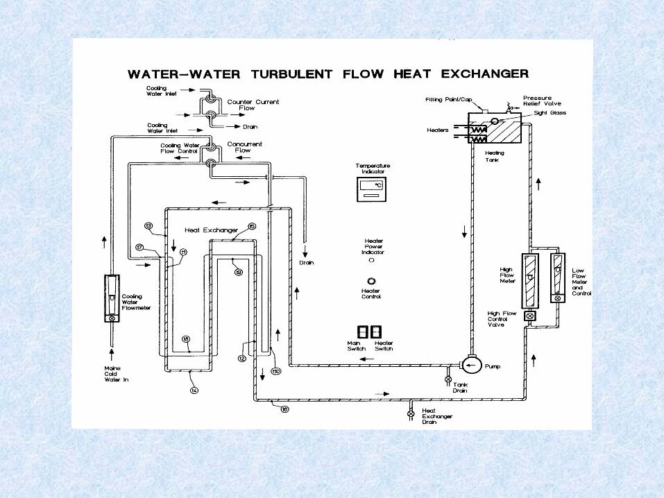
ExperimentalApparatus
• Two copper concentric pipes•Inner pipe (ID = 7.9 mm, OD = 9.5 mm, L = 1.05 m)
•Outer pipe (ID = 11.1 mm, OD = 12.7 mm)
•Thermocouples placed at 10 locations along exchanger, T1 through T10
Hot Flow Rotameters
Temperature Indicator
Cold Flow rotameter
Heat Controller
Switch for concurrent and countercurrent flow
Temperature Controller
0
50
100
150
200
250
150 2150 4150 6150 8150 10150 12150
Pr^X Re^Y
Nus
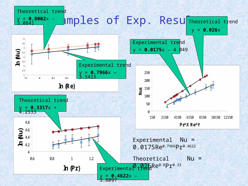
Examples of Exp. Results
4
4.2
4.4
4.6
4.8
0.6 0.8 1 1.2 1.4
ln (Pr)
ln (N
u)
2
2.5
3
3.5
4
4.5
5
5.5
6
9.8 10 10.2 10.4 10.6 10.8 11
ln (Re)
ln (N
u)Theoretical trend
y = 0.8002x – 3.0841
Experimental trend
y = 0.7966x – 3.5415
Theoretical trend
y = 0.3317x + 4.2533
Experimental trend
y = 0.4622x – 3.8097
Theoretical trend
y = 0.026x
Experimental trend
y = 0.0175x – 4.049
Experimental Nu = 0.0175Re0.7966Pr0.4622
Theoretical Nu = 0.026Re0.8Pr0.33
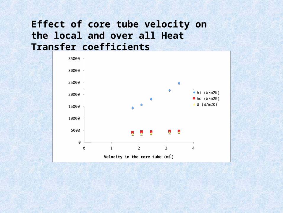
0
5000
10000
15000
20000
25000
30000
35000
0 1 2 3 4
Velocity in the core tube (ms-1)
Heat
Tran
sfer
Coeffi
cien
t W
m-2
K-
hi (W/m2K)
ho (W/m2K)
U (W/m2K)
Effect of core tube velocity on the local and over all Heat Transfer coefficients