heat treatment metals, plastics and surface finishing
TRANSCRIPT
Madein Germanywww.nabertherm.com
Heat Treatment Metals, Plastics and Surface Finishing
Furnaces and Systems for Tempering Annealing/HardeningQuenchingSolution AnnealingBrazingForgingCuring PreheatingDryingAgeing

Heat Treatment of Metals,Plastics and Surface Finishing
Made in GermanyNabertherm with more than 350 employees worldwide have been developing and producing industrial furnaces for many different applications for over 60 years. 150,000 satisfied customers in 100 countries offer proof of our commitment to build quality equipment cost-effectively. Short delivery times are ensured due to our complete inhouse production and our wide variety of standard furnaces.
Setting Standards in Quality and ReliabilityOur products range from standard furnaces to flexible, state-of-the-art fully automatic systems and plants with material handling technology. Your complete heat treatment production process can be realized through our customized solutions.
Innovative Nabertherm control technology provides for precise control as well as full documentation and remote monitoring of your processes. Our engineers apply state-of-the-art technology to improve the temperature uniformity, energy efficiency, reliability and durability of our systems with the goal of enhancing your competitive edge.
Global Sales and Service Network – Close to youWith our global sales network, we can offer on-site customer service wherever you choose to produce. Long term sales and distribution partners in all important world markets ensure individual on-site customer service and consultation. There are various reference customers in your neighborhood who have similar furnaces or systems.
Customer Service and Spare PartsOur professional service engineers are available for you world-wide. Due to our complete inhouse production, we can despatch spare parts from stock or produce with short delivery time.
More Than Heat – Experience in Many Fields of Thermal ProcessingIn addition to furnaces for heat treatment, Nabertherm offers a wide range of standard furnaces and systems for many other thermal processing applications. The modular design of our products allows us to customize a solution to your individual needs without expensive modifications. Our professional R&D department will be pleased to test your product samples in order to specify the right heat treatment equipment for you.
�
PageFurnaces with Air Circulation
Low-Temperature Bogie Hearth Furnaces, heated electrically or with Gas ................................................... 4Bogie Hearth Furnaces, heated electrically or with Gas ............................................................................ 6Pit-Type Furnaces .............................................................................................................................. 8Low-Temperature Chamber Furnaces, heated electrically or with Gas .......................................................10Chamber Furnaces ............................................................................................................................1�Chamber furnaces with Cleanroom technics ..........................................................................................13Annealing Boxes for Protective Atmospheres used in Chamber and Pit-Type Furnaces .................................14Gastight Chamber Furnaces for Protective Atmosphere ..........................................................................15Chamber Furnaces with Safety Controls for Materials containing Solvents, acc. to EN 1539 .........................16Ovens TR 60 - TR 1050 up to 300 °C ....................................................................................................17
Furnaces with Radiation HeatingBogie Hearth Furnaces, heated electrically or with Gas .......................................................................... 18Chamber Furnaces ........................................................................................................................... �0
Protective Gas and Carburizing Systems ............................................................................................ ��
Tool Shop Hardening Systems ............................................................................................................ �4
Protective Gas Hardening System, Accessories for the Hardening Shop(please ask for our extensive Catalogue)............................................................................................ �5
Martempering Furnaces using Neutral Salts ....................................................................................... �6
Salt-Bath Furnaces, electrically (TS) or gas heated (TSB) for Heat Treatment of Steel or Light Metals ...................................................................................................................... �7
Strand and Wire-Drawing Furnaces .................................................................................................... �8
Continuous Furnaces .......................................................................................................................... �9
Charging Devices and Accessories for Chamber and Bogie Hearth Furnaces ..................................... 30
Plants and Systems Concepts, e.g. Heat Treatment Plants ................................................................ 3�
Retort Furnace with or without Gas CirculationProtective Gas Retort Furnaces with Indirect Heating Outside the Retort .................................................. 34Pit-Type Retort Furnaces with integrated Protective Gas Retort ............................................................... 36
Plants with catalytic and thermal Afterburning Systems ......................................................................37
Process Control and Documentation .................................................................................................. 38
Professional Control and Documentation Alternatives ........................................................................ 39
Contents
3

Low-Temperature Bogie Hearth Furnaces with Air CirculationHeated electrically or with Gas
W(B) 5800/26AS - W 18790/45ASFor processes such as normalizing, ageing, curing, or preheating that include a heat treatment of heavy charges, we recommend our low-temperature bogie hearth furnaces. These furnaces are available for maximum working temperatures of �60 °C or 450 °C. They can be heated either electrically or with gas.
Maximum temperatures of �60°C or 450 °CBogie on rails for weights up to 50 tonsSwing door hinged on the rightHeated electrically (W) or with gas (WB)Electrical heating of the furnace by means of heater coilsDirect gas heating or upon request with indirect gas heating with radiation tube, e.g. for heat treatment of aluminumOptimum temperature uniformity (according to DIN 1705�-1) up to ΔT 6 KPowerful fan with vertical air circulationOptimal air circulation with help of adjustable air outlets tailored to charge requirementAir inlet and exhaust air vent, manually adjustableHigh circulation rate for fast and steady heat transferFurnace chamber lined with alloy 314 (AISI)/(DIN material no. 1.4841) stainless steel on 450 °C modelsOver-temperature limit controller with adjustable cutout temperature for thermal protection class in accordance with EN 60518-� as temperature limiter to protect the oven and loadFor control systems see page 38/39
Indirectly gas-heated bogie hearth furnace, with electrical bogie drive, vertical air circulation used for artificial ageing of aluminum pistons with charge weights of approx. � tons
Enclosed heating coils for modelswith electric heating
Gas burner firing into a radiant tube for models with gas heating
Model Tmax Inner dimensions in mm Volume Outer dimensions in mm Circulation Heating Electrical°C w d h in l W D H rate m³/h power/kW connections*
W(B) 5800/�6AS �60 1100 �400 ��00 5800 1980 3500 3400 1�600 180 3-phaseW(B) 17�80/�6AS �60 �400 4000 1800 17�80 3900 4400 3000 36000 �40 3-phaseW(B) �1875/�6AS �60 �500 3500 �500 �1875 3400 4300 3400 36000 �66 3-phaseW(B) �8800/�6AS �60 �400 8000 1500 �8800 3600 8400 �700 48000 360 3-phase
W(B) �380/45AS 450 1100 1600 1350 �380 1600 �650 1850 6400 70 3-phaseW(B) 18790/45AS 450 1790 6000 1750 18790 3300 7�00 �950 36000 300 3-phase
*Please see page 38 for more information about supply voltage4
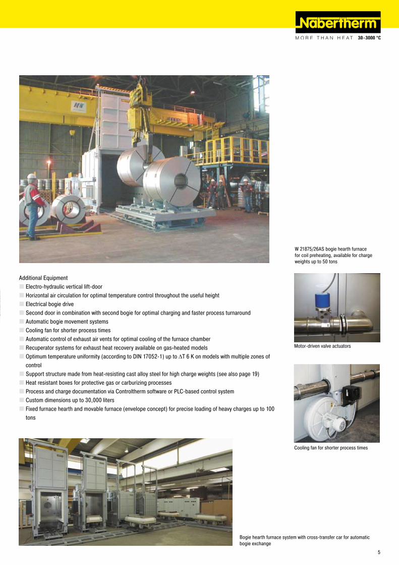
Additional EquipmentElectro-hydraulic vertical lift-doorHorizontal air circulation for optimal temperature control throughout the useful heightElectrical bogie driveSecond door in combination with second bogie for optimal charging and faster process turnaroundAutomatic bogie movement systemsCooling fan for shorter process timesAutomatic control of exhaust air vents for optimal cooling of the furnace chamberRecuperator systems for exhaust heat recovery available on gas-heated modelsOptimum temperature uniformity (according to DIN 1705�-1) up to ΔT 6 K on models with multiple zones of controlSupport structure made from heat-resisting cast alloy steel for high charge weights (see also page 19)Heat resistant boxes for protective gas or carburizing processesProcess and charge documentation via Controltherm software or PLC-based control systemCustom dimensions up to 30,000 litersFixed furnace hearth and movable furnace (envelope concept) for precise loading of heavy charges up to 100 tons
Cooling fan for shorter process times
Motor-driven valve actuators
W �1875/�6AS bogie hearth furnace for coil preheating, available for charge weights up to 50 tons
Bogie hearth furnace system with cross-transfer car for automatic bogie exchange
5

Bogie Hearth Furnaces with Air Circulation Heated electrically or with gas
W 1000/65A - W 10000/85AFor processes such as solution annealing, artificial ageing, or soft annealing requiring high temperature uniformity and optimum charging ability for heavy charge weights,we recommend bogie hearth furnaces with air circulation.
Maximum temperatures of 650 °C or 850°CBogie on railsSwing door hinged on the rightElectrically heating of two sides and bogieOptimum temperature uniformity (according to DIN 1705�-1) up to ΔT 14 KPowerful fan with vertical air circulationAir baffles at furnace sides for optimal air circulationOver-temperature limit controller with adjustable cutout temperature for thermal protection class in accordance with EN 60519-� as temperature limiter to protect the oven and loadFor control systems see page 38/39
Bogie hearth furnace W 5440/85AS with automated bogie change, electro-hydraulic lift-door, safety technology for flammable atmospheres and charge documentation
Motor driven chain drive for bogie as additional equipment
Vertical air circulation with air baffles on furnace sides
Model Tmax Inner dimensions in mm Volume Outer dimensions in mm Supply Electrical°C w d h in l W D H power/kW connections*
W 1000 /65A 650 800 1600 800 1000 1450 �400 �300 4� 3-phaseW 1000 /65AS1 650 1000 1000 1000 1000 1650 1800 �500 4� 3-phaseW 1500 /65A 650 900 1900 900 1500 1550 �750 �400 58 3-phaseW 1500 /65AS1 650 1000 1500 1000 1500 1650 �300 �500 58 3-phaseW ��00 /65A 650 1000 ��00 1000 ��00 1650 3000 �500 77 3-phaseW 3300 /65A 650 1000 3300 1000 3300 1650 4000 �500 90 3-phaseW 4000 /65AS1 650 1500 ��00 1�00 4000 �150 3000 �700 110 3-phaseW 5000 /65A 650 1�00 3400 1�00 5000 1850 4100 �700 110 3-phaseW 7500 /65A 650 1400 3800 1400 7500 �050 4500 �900 140 3-phaseW 10000 /65A 650 1600 3900 1600 10000 ��50 4600 3100 ��0 3-phase
W 1000 /85A 850 800 1600 800 1000 1450 �400 �300 4� 3-phaseW 1500 /85A 850 900 1900 900 1500 1550 �750 �400 58 3-phaseW ��00 /85A 850 1000 ��00 1000 ��00 1650 3000 �500 77 3-phaseW 3300 /85A 850 1000 3300 1000 3300 1650 4000 �500 90 3-phaseW 5000 /85A 850 1�00 3400 1�00 5000 1850 4100 �700 110 3-phaseW 7500 /85A 850 1400 3800 1400 7500 �050 4500 �900 140 3-phaseW 10000 /85A 850 1600 3900 1600 10000 ��50 4600 3100 ��0 3-phase
*Please see page 38 for more information about supply voltage
6

Bogie hearth furnace with air circulation and customized load supports for cylindrical loads
Additional EquipmentPowerful direct gas heatingFixed hearth and movable furnace (envelope concept) for heavy charges up to 100 tonsElectro-hydraulic vertical lift-doorHorizontal air circulation for optimal temperature throughout the useful heightElectrical bogie driveSecond door in combination with second bogie for alternating operation and optimal chargingFully automatic bogie changeFan system for faster coolingAutomatic control of exhaust air vents for optimal cooling of the furnace chamberOptimal temperature uniformity (according to DIN 1705�-1) up to ΔT 6 K on models with multiple zones of controlSupport structure made from heat-resisting cast alloy steel for high charge weights (see also page 19)Heat-resistant boxes for protective gas or carburization processesProcess and charge documentation via Controltherm software or PLC-based control systemCustom dimensions up to 30,000 liters
Bogie hearth furnace W 4000/65 HA with charging basket
Bogie hearth furnace W 10370/65AS
Steel grid on bogie for charging heavy loads and wall elements protected by SiC tiles
7

S �50/65A
Pit-Type Furnaces with Air Circulation
S 30/45A - S 500/85APit-type furnaces with air circulation offer the advantage of easy charging, for heat treatment of heavy parts or loads in charge baskets. With maximum application temperatures available from 450 °C to 850 °C, these compact furnaces are particularly useful for processes such as tempering, solution annealing, artificial ageing, and soft annealing.
Maximum temperatures of 450 °C, 650 °C, 850 °CAir circulation fans in the furnace bottom, high circulation rateVertical air circulation with square air heating chamberOptimum temperature uniformity (according to DIN 1705�-1) up to ΔT 4 KInterior walls from stainless steelSwitchgear with solid-state relaysFor control systems see page 38/39
Additional EquipmentCharging hoist with swivel arm and charge basketIntegrated fan for rapid cool down or separate cooling station for retort box cooling outside of the furnaceRetort box with protective gas inlet and outlet for production in a defined atmosphere (see page 14)Manual or automatic gas supply systems (see page 14)
Pit-type furnace S �50/65A with protective gas retort allowing bright annealing (see page 14)
S 1�0/65A with protective gas retort box and cooling station next to the furnace
S 30/65HA with exchangeable retort and two retort air cooling devices
Model Tmax Inner dimensions in mm Volume Outer dimensions in mm Supply Electrical Weight°C w d h in l W D H power/kW connections* in kg
S 30/45A 450 300 �50 400 30 750 850 1�50 3,6 1-phase 130S 60/45A 450 350 350 500 60 800 950 1350 6,6 3-phase ��5S 1�0/45A 450 450 450 600 1�0 900 1050 1450 9,6 3-phase �80S �50/45A 450 600 600 750 �50 1050 1�00 1600 19,0 3-phase 750S 500/45A 450 750 750 900 500 1�00 1350 1750 �8,0 3-phase 980
S 30/65A 650 300 �50 400 30 750 850 1�50 6,0 3-phase¹ 130S 60/65A 650 350 350 500 60 800 950 1350 9,6 3-phase ��5S 1�0/65A 650 450 450 600 1�0 900 1050 1450 13,6 3-phase �80S �50/65A 650 600 600 750 �50 1050 1�00 1600 �1,0 3-phase 750S 500/65A 650 750 750 900 500 1�00 1350 1750 31,0 3-phase 980
S 30/85A 850 300 �50 400 30 600 740 1000 6,0 3-phase¹ 130S 60/85A 850 350 350 500 60 800 950 1350 9,6 3-phase ��5S 1�0/85A 850 450 450 600 1�0 900 1050 1450 13,6 3-phase �80S �50/85A 850 600 600 750 �50 1050 1�00 1600 �1,0 3-phase 750S 500/85A 850 750 750 900 500 1�00 1350 1750 31,0 3-phase 980¹Heating only beetween two phases *Please see page 38 for more information about supply voltage
8

S 1000/A
3 x S �00/A
S 4100/65AS
S 100/A - S 1000/ADue to their robust design, these pit-type furnaces with air circulation are particularly useful for a professional heat treatment demanding optimum temperature accuracy. Production processes such as tempering, solution annealing, artificial ageing, and soft annealing can be realized with these pit-type furnaces.
Maximum temperature of 750 °CUseful for heavy charge weightsAir circulation fans in the furnace lid, high circulation rateHeating chamber with air baffle cylinderHeating elements on all wall surfacesDistribution of air flow through grid at the furnace floorPneumatic or hydraulic lid liftingOptimum temperature uniformity (according to DIN 1705�-1) up to ΔT 4 KFor control systems see page 38/39
Additional EquipmentIntegral fan for fast coolingVariable rpm converter control of the air circulation velocity for sensitive partsMultiple zone control or special air circulation system for optimum temperature uniformity tailored to the chargeCustom dimensions up to 10,000 litersCharge weights up to 7 tons
Model Tmax Inner dimensions cond. cylinder Volume Outer dimensions in mm Supply Electrical Weight°C Ø in mm h in mm in l W D H power/kW connections* in kg
S 100/A 750 450 600 100 1100 1�00 1600 17,5 3-phase 1000S �00/A 750 600 800 �00 1�00 1300 �050 �8,5 3-phase 1300S 300/A 750 600 1000 300 1�00 1300 ��50 39,5 3-phase 1500S 500/A 750 800 1000 500 1400 1600 �400 5�,5 3-phase 1600S 600/A 750 800 1�00 600 1400 1600 �600 6�,5 3-phase 1800S 800/A 750 1000 1000 800 1600 1800 �400 70,0 3-phase 1900S 1000/A 750 1000 1300 1000 1600 1800 �700 90,0 3-phase ��00
*Please see page 38 for more information about supply voltage
9

N 39�0/�6HAS
N 560/26 A - N 10000/45 A and N 560/26 HA - N 10000/45 HAThese low-temperature chamber furnaces are available for maximum working temperatures of �60 °C or 450 °C. They can be used for various processes such as preheating, drying, curing, artificial ageing, soft annealing, and tempering. These furnaces are suited for use with baskets, pallets as well as mobile furnace racks. The charging can be carried out with fork lift, pallet truck or charging trolley. All furnaces are available with electric or gas heating.
Maximum Temperatures up to �60 °C or 450 °CHeated electrically or with gasElectrical heating by means of heater coilsDirect gas heating or upon request with indirect gas heating with radiation tube, e.g. for heat treatment of aluminumAvailable with horizontal (type/HA) or vertical air circulation (type/A) for optimal uniformity in your chargeGround level charging without floor insulation for �60 °C modelsOptimum temperature uniformity (according to DIN 1705�-1) up to ΔT 10 KOptimal air circulation for your charge by means of adjustable air outletsFurnace chamber lined with alloy 314 (AISI)/(DIN material no. 1.4841) for 450 °C modelsLow shell temperature by means of high quality mineral wool insulationManually adjustable air inlet and exhaust air ventHigh air exchange for fast drying processesFurnace sizes suitable for common charging systems, such as pallets, baskets, etc.Double-wing door for furnaces N 1500/.. and largerOver-temperature limit controller with adjustable cutout temperature for thermal protection class in accordance with EN 60519-� as temperature limiter controler to protect the oven and loadFor control system see page 38/39
Additional EquipmentOptional floor insulation for improved temperature uniformity on �60 °C modelsEntry ramp or track cutouts for floor-level charging of models with insulated bottomElectro-hydraulic lift-doorFan system for faster cooling with manual or automatic controlAutomatic control of exhaust air vents for better ventilation of the furnace chamberWindow and furnace chamber illumination
Low-Temperature Chamber Furnaces with Air CirculationHeated electrically or with gas
Enclosed heater coils on electrically heated models
Gas burner firing into a radiant tube
N 4000/�6HA with lift-door
10

Drive-in tracks for pallet truck or charging trolley
Charging on different levels
� x N 1�000/�6S with charge racks for preheating of moulds
Model Tmax Inner dimensions in mm Volume Outer dimensions in mm Circulation Supply Electrical°C w d h in l W D H rate m³/h power/kW connections*
N 560/�6.. �60 750 1000 750 560 1450 1865 ���0 900 13,0 3-phaseN 1000/�6.. �60 1000 1000 1000 1000 1930 1900 1600 3600 18,0 3-phaseN 1500/�6.. �60 1500 1000 1000 1500 �380 1900 1600 3600 ��,0 3-phaseN 1500/�6..1 �60 1000 1500 1000 1500 1880 �400 1600 3600 ��,0 3-phaseN �000/�6.. �60 1500 1100 1�00 �000 �380 �000 1800 6400 ��,0 3-phaseN �000/�6..1 �60 1100 1500 1�00 �000 1980 �400 1800 6400 ��,0 3-phaseN �010/�6.. �60 1000 1000 �000 �000 1880 1900 �7�0 7�00 30,0 3-phaseN �880/�6.. �60 1�00 1�00 �000 �880 �080 �100 �7�0 9000 54,0 3-phaseN 4000/�6.. �60 1500 ��00 1�00 4000 �380 3110 1800 9000 47,0 3-phaseN 4000/�6..1 �60 ��00 1500 1�00 4000 3080 �410 1800 9000 47,0 3-phaseN 4010/�6.. �60 1000 �000 �000 4000 1880 �900 �7�0 9000 54,0 3-phaseN 4500/�6.. �60 1500 1500 �000 4500 �380 �400 �7�0 1�800 54,0 3-phaseN 5600/�6.. �60 1500 �500 1500 5600 �110 3180 �340 9000 69,0 3-phaseN 6750/�6.. �60 1500 3000 1500 6750 �110 3680 �340 19�00 98,0 3-phaseN 7�00/�6.. �60 �000 1500 �400 7�00 �610 �410 3000 18000 93,0 3-phaseN 10000/�6.. �60 �000 �500 �000 10000 �610 3180 �840 �5600 106,0 3-phase
N 560/45..E 450 750 1000 750 560 1450 1865 ���0 900 13,0¹/ 19,0 3-phaseN 1000/45..E 450 1000 1000 1000 1000 1930 1900 1600 3600 18,0¹/ 40,0 3-phaseN 1500/45..E 450 1500 1000 1000 �380 1900 1600 13�0 3600 ��,0¹/ 40,0 3-phaseN 1500/45..1E 450 1000 1500 1000 1500 1880 �400 1600 3600 ��,0¹/ 40,0 3-phaseN �000/45..E 450 1500 1100 1�00 �000 �380 �000 1800 6400 ��,0¹/ 46,0 3-phaseN �000/45..1E 450 1100 1500 1�00 �000 1980 �400 1800 6400 ��,0¹/ 46,0 3-phaseN �010/45..E 450 1000 1000 �000 �000 1880 1900 �7�0 7�00 30,0¹/ 54,0 3-phaseN �880/45..E 450 1�00 1�00 �000 �880 �080 �100 �7�0 9000 54,0¹/ 66,0 3-phaseN 4000/45..E 450 1500 ��00 1�00 4000 �380 3110 1800 9000 47,0¹/ 65,0 3-phaseN 4000/45..1E 450 ��00 1500 1�00 4000 3080 �410 1800 9000 47,0¹/ 65,0 3-phaseN 4010/45..E 450 1000 �000 �000 4000 1880 �900 �7�0 9000 54,0¹ 66,0 3-phaseN 4500/45..E 450 1500 1500 �000 4500 �380 �400 �7�0 1�800 54,0¹/ 66,0 3-phaseN 5600/45..E 450 1500 �500 1500 5600 �110 3180 �340 9000 69,0¹/ 93,0 3-phaseN 6750/45..E 450 1500 3000 1500 6750 �110 3680 �340 19�00 98,0¹/116,0 3-phaseN 7�00/45..E 450 �000 1500 �400 7�00 �610 �410 3000 18000 93,0¹/117,0 3-phaseN 10000/45..E 450 �000 �500 �000 10000 �610 3180 �840 �5600 106,0¹/130,0 3-phase¹Reduced connected power for plastics applications *Please see page 38 for more information about supply voltage
Safety technology according to EN 1539 for charges containing solvents (see page 16)Catalytic or thermal exhaust gas cleaning systemsCustom sizes up to 30,000 liters and charge weights up to 30 tons
11

N 1�0/65 HA
Chamber Furnaces with Air Circulation
N 15/65HA, N 30/45HA - N 500/85HA
These classic chamber furnaces with air circulation offer remarkable temperature accuracy and are therefore particularly useful for processes such as tempering, curing, solution annealing, artificial ageing, preheating, and soft annealing. With their modular design, these furnaces can be equipped with useful accessories, allowing nearly limitless customizations for all your different process conditions.
Maximum temperatures of 450 °C, 650 °C, or 850 °CHorizontal air circulationSwing door hinged on the rightOptimum temperature uniformity (according to DIN 1705�-1) up to ΔT 6 KHeating from bottom, sides and topOptimum air flow and temperature uniformity through high circulation ratesOne shelf and rails for two additional shelves includedAir baffle box of stainless steel inside the furnace chamber for optmum air circulationSwitchgear with solid-state relaysFor control system see page 38/39
N �50/65HA with pneuma-tic lift-door as additional equipment
Model Tmax Inner dimensions in mm Volume Outer dimensions in mm Supply Electrical Weight°C w d h in l W D H power/kW connections* in kg
N 30/45 HA 450 �90 4�0 �60 30 607 + �55 1175 1315 3,6 1-phase 195N 60/45 HA 450 350 500 350 60 667 + �55 1�50 1400 6,6 3-phase �40N 1�0/45 HA 450 450 600 450 1�0 767 + �55 1350 1500 9,6 3-phase 310N �50/45 HA 450 600 750 600 �50 100� + �55 1636 1860 19,0 3-phase 610N 500/45 HA 450 750 1000 750 500 115� + �55 1886 �010 �8,0 3-phase 1030
N 15/65 HA¹ 650 �95 340 170 15 470 845 460 �,7 1-phase 55N 30/65 HA 650 �90 4�0 �60 30 607 + �55 1175 1315 6,0 3-phase² 195N 60/65 HA 650 350 500 350 60 667 + �55 1�50 1400 9,6 3-phase �40N 1�0/65 HA 650 450 600 450 1�0 767 + �55 1350 1500 13,6 3-phase 310N �50/65 HA 650 600 750 600 �50 100� + �55 1636 1860 �1,0 3-phase 610N 500/65 HA 650 750 1000 750 500 115� + �55 1886 �010 31,0 3-phase 1030
N 30/85 HA 850 �90 4�0 �60 30 607 + �55 1175 1315 6,0 3-phase² 195N 60/85 HA 850 350 500 350 60 667 + �55 1�50 1400 9,6 3-phase �40N 1�0/85 HA 850 450 600 450 1�0 767 + �55 1350 1500 13,6 3-phase 310N �50/85 HA 850 600 750 600 �50 100� + �55 1636 1860 �1,0 3-phase 610N 500/85 HA 850 750 1000 750 500 115� + �55 1886 �010 31,0 3-phase 1030¹Table-top model, see page �4 *Please see page 38 for more information about supply voltage²Heating only beetween two phases
1�

Additional Equipment N 30/45HA - N 500/85HACooling system with fan for fast coolingAutomatic control of air inlet and exhaust air vents for better ventilation and faster cooling of the furnacePneumatic lift-doorAtmosphere boxes for protective gas operation (see also page 30/31)Additional shelvesVariable frequency control of air circulation velocity for sensitive partsCharging aids, roller conveyors (see also page 30/31)Custom sizes up to 10,000 liters and charge weights up to 10 tons
N 120/65HAC - N 500/65HACFor some heat treatment processes it is important to reduce dust contamination in the furnace chamber down to a minimum. To achieve highest protection for these applications these specific chamber furnaces with welded inner box and insulation fully covered with stainless steel sheets are recommended.
Horizontal airflowSealed housingInsulation covered with stainless steel sheetsOptimum temperature uniformity at �50 °C - 650 °C of up to ΔT 6 K in accordance to DIN 1705�-1Operation under protective gases as an option
N 120/45 HACLS - N 500/45HACLS with Safety Technology according to EN 1539If liquid solvents are present in the materials heat treated, this line of furnaces may be equipped with additional safety technology according to EN 1539 for processing at temperatures up to 450 C. (see page 16).
Model Tmax Inner dimensions in mm Outer dimensions in mm Supply power/ Electrical°C w d h W D H kW connections*
N 1�0/65 HAC 650 450 600 450 900 + �55 1600 1600 9,6 3-phaseN �50/65 HAC 650 600 750 600 1050 + �55 1750 1750 18,6 3-phaseN 500/65 HAC 650 750 900 750 11�0 + �55 1900 1900 �7,6 3-phase *Please see page 38 for more information about supply voltage
N 500/HAC with Cleanroom technicsChamber furnaces with Cleanroom technics
13

Annealing Boxes for a defined Protective Atmosphere for use in Chamber and Pit-Type Furnaces with Air Circulation
Annealing Boxes for Models N 30/45 HA - N 500/85 HA, S 30/45A - S 500/85AUsing annealing boxes, you can operate our standard air circulation furnaces, modelsN 30/45 HA - N 500/85 HA and models S 30/45 A - S 500/85A, under a defined protective atmosphere. This allows processes such as bright annealing, annealing under protective gas, or curing of copper alloys.
On standard models, the boxes are equipped with a lid and a protective gas inlet and outlet. The lid is sealed by means of a sealing groove with a fibre gasket before loading into the furnace. The furnace is equipped with a special pass-through for the box inlet and outlet connections. The box inlet is connected to a gas supply panel. We have gas supply panels available for either manual or automatic control.
As a vacuum model, the box allows air evacuation in cold condition before refilling with protective gas. This system is particularly useful for bright annealing of bulk materials, since the oxygen can be more efficiently removed from the box by means of pre-evacuation than through purging alone. In our modern research center we can carry out tests and experiments to demonstrate how these boxes perform with your materials.
Protective gas inlet and outletSealing groove with fibre gasketMade of high heat-resistant stainless steel alloy 314 (AISI)/(DIN material no. 1.4841)
Additional EquipmentReinforced box with special seals for room-temperature vacuum use, particularly useful for bulk material heat treatment and low pre-purging gas consumptionVacuum pumping station for box evacuation, including connection set and three-way valveGas supply panel with manual or automatic controls
For more details on the available sizes of our protective gas boxes and other important information, please see page 25 of our Heat Treatment II catalog.
N �50/65HA with protective gas annealing box
S 1�0/65A with annealing box and cooling plat-form for process time reduction
Automatic gas supply panel for annealing box
Vacuum pump for evacuating the box while cold
14

N 1�0/65SHA
N 500/65SHA
Gas-Tight Chamber Furnaces with Air Circulation for Protective Gas Atmospheres
N 15/65 SHA - N 500/65 SHABased on the standard furnaces N 30/65 HA et. al., these furnace models with air circulation are equipped with a specially sealed housing and protective gas inlet and outlet. The furnaces can be used for inert gas heat treatment allowing tempering, annealing under protective gas, and curing. You can use them also for heat-treating magnesium under certain conditions. While these furnaces are not appropriate for furnaces that require a high-purity atmosphere, they offer a compelling value for more forgiving processes.
Maximum temperature of 650 °CHorizontal air circulationOptimum temperature uniformity (according to DIN 1705�-1) up to ΔT 6 KManual gas supply panel with pressure reducer and flow meter for use with all non-combustible protective gases such as nitrogen, argon or forming gasHeating from bottom, sides and topHigh gas circulation rate for optimal uniformitySupplied standard with one shelf and rails for two additional shelvesAir baffle box of stainless steel inside the furnace chamber for optmum air circulationSwitchgear with solid-state relaysFor control system see page 38/39
Additional EquipmentAutomatic gas supply panel, including pressure reducer, flow meter, solenoid valves, timerAdditional shelvesCharging aids, roller conveyor (see also page 30/31)
Model Tmax Inner dimensions in mm Volume Outer dimensions in mm Supply Electrical Weight°C w d h in l W D H power/kW connections* in kg
N 15/65SHA 650 �95 340 170 15 470 845 460 �,7 1-phase 55N 30/65SHA 650 �90 4�0 �60 30 607 + �55 1175 1315 6,0 3-phase¹ 195N 60/65SHA 650 350 500 350 60 667 + �55 1�50 1400 9,6 3-phase �40N 1�0/65SHA 650 450 600 450 1�0 767 + �55 1350 1500 13,6 3-phase 310N �50/65SHA 650 600 750 600 �50 100� + �55 1636 1860 �1,0 3-phase 610N 500/65SHA 650 750 1000 750 500 115� + �55 1886 �010 31,0 3-phase 1030¹Heating only beetween two phases *Please see page 38 for more information about supply voltage
15

Electrically heated convection cham-ber furnace with air circulation N 4000/�6HACLS for drying of foundry cores with an alcohol-based binder
Chamber Furnaces with Air Circulationwith Safety Technology for Materials containing Solvents according to EN 1539 or NFPA 86
Special door sealing with circular sealing lip
Exhaust port and powerful exhaust fan mounted on the furnace
Ship-lock type furnace N 560/�6HACLS with safety technology, front charging and rear unloading
Safety Technology for Chamber FurnacesCertain processes release solvents or evolve other flammable vapors when heat is applied. The concentration of these vapors must be kept below a certain limit to prevent ignition. European Norm EN 1539 (formerly VGB4) and NFPA 86 in the USA proscribe the required safety equipment for these processes.
For appropriate applications and processes, all air circirculation furnaces of the series N ..HACLS (pages 10, 11 and 13) are available with safety technology for protection of ignition in the furnace chamber.
To prevent ignition, flammable vapors must be diluted with air. Special care must be taken so high concentrations of flammable materials do not accumulate in “dead” areas within the furnace. For this purpose, the furnaces are equipped with an exhaust gas fan, providing a defined suction flow. A measurement system monitors this flow. In parallel, the furnace atmosphere is diluted by the inflow of fresh air. The air circulation is also monitored by the measurement system. Furnaces with a capacity greater than 1000 liters are additionally equipped with an explosion pressure relief.
Defined and monitored exhaust air flowPowerful exhaust fan capable of maintaining negative furnace pressureDefined and monitored air circulation flowEmergency Stop ButtonVisual and audible emergency signalsOver-temperature limit controller with adjustable cutout temperature for thermal protection class in accordance with EN 60519-� as temperature limiter to protect the oven and loadFor control system see page 38/39
For technical specifications of furnaces, see page 4/5, and 10/11
Max. amount of solvent at temp. in grams per charge per EN 1539
N 56
0/..
N 10
00/..
N 15
00/..
N �0
00/..
N �0
10/..
N 39
�0/..
N 40
00/..
N 40
10/..
N 45
00/..
N 56
00/..
N 67
50/..
N 7�
00/..
N 10
000/
..
150 °C 37 71 76 9� 9� 16� 16� 16� 17� 183 ��5 �35 �63�00 °C �6 50 57 69 99 1�1 1�1 1�1 13� 139 171 180 �03�50 °C �1 39 45 55 55 96 96 96 98 11� 137 145 165
16

TR �40/S with view window
Ovens TR 60 - TR 1050 up to 300 °C
Over-temperature limit controller
Model Tmax Inner dimensions in mm Volume Outer dimensions in mm Power Electrical Weight Trays in-
Trays Max.total
°C w d h in L W D H kW connection* in kg cluded max. load¹TR 60 300 490 360 340 60 650 550 640 �,1 single-phase 45 1 4 1�0TR 1�0 300 600 360 480 105 750 550 780 �,1 single-phase 70 � 7 150TR �40 300 700 550 640 �40 860 730 940 3,1 single-phase 100 � 9 150TR 4�0 300 710 550 1080 4�0 860 830 1370 4,0 3-phase 1�0 3 17 150TR 1050 300 1�40 570 1510 1050 1430 860 19�0 9,3 3-phase 380 4 �� 170¹Max load per layer 30 kg *Please see page 38 for information on mains voltage
TR 60 - TR 1050With their maximum working temperature of 300 °C and forced air circulation, the TR series ovens achieve very good temperature uniformity. They can be used for various applications such as e.g. drying, sterilizing or warm storing. The stainless steel interior chamber is easy to clean and resistant to rust.
Tmax 300 °COperating range, room temperature + 5 °C to 300 °CModels TR 60 - TR �40 designed as tabletop modelsModels TR 4�0 and TR 1050 designed as floor standing modelsHorizontal, forced air circulation results in temperature distribution better than ΔT 8 KStainless steel chamber, material 1.4301, rust-resistant and easy to cleanCharging in multiple layers possible using removeable trays (number of removeable trays included, see table below)Large, wide-opening swing door, hinged on the right with quick release for models TR 60 - TR 4�0Double swing door with quick release for TR 1050Exhaust vent in the rear wallPID microprocessor control with self-diagnosis systemSilent solid-state power control relaysPlease see page 38 for a description of various controllers
Additional EquipmentOver-temperature limit controller with adjustable cutout temperature for thermal protection class � in accordance with EN 60519-� as temperature limiter to protect the furnace and loadWindow for charge observingFurther removeable trays with rails
TR 1050 with double door
TR 60
17

W 1500/H
Bogie Hearth FurnacesHeated electrically or with gas
Cooling fan for shorter process cycles
W 1000/G - W 10000For annealing and hardening of large parts, like heavy cast parts or tool steel dies to temperatures between 800 °C and 1�00 °C, we recommend our bogie hearth furnaces with radiation heating. The bogie can be conveniently loaded outside the furnace. With a second door or bogie-transfer system, one bogie can be charged outside the furnace while the other bogie is in the furnace. This way, turnaround time between process cycles will be reduced substantially.
Maximum temperatures of 900 °C or 1�80 °CDouble-walled housing with rear ventilation, provides low shell temperaturesSwing door hinged on the right sideHeating from five sides (four sides and bogie) provides for a uniform temperature distributionAutomatic power connection to the bogie when moved into the furnaceHeating elements mounted on support tubes provide for free radiation and long service lifeFloor heating protected by SiC tiles on the bogie providing level stacking surfaceMulti-layer insulation consisting of lightweight refractory bricks backed by microporus silica insulationSelf-supporting roof archBogie on rails incl. rails in front of the furnace for chargingAdjustable air inlet damperManual vapor vent on the furnace roofFor control system see page 38/39
Model Tmax Inner dimensions in mm Volume Outer dimensions in mm Supply Electrical Weight°C w d h in l W D H power/kW connections* in kg
W 1000/G 900 800 1600 800 1000 1400 �350 1880 57 3-phase 3000W 1500/G 900 900 1900 900 1500 1500 �650 �010 75 3-phase 3500W ��00/G 900 1000 ��00 1000 ��00 1600 �950 �1�0 110 3-phase 4000W 3300/G 900 1000 �800 1�00 3300 1600 3550 �3�0 140 3-phase 5300W 4100/G 900 1�00 �800 1�00 4040 1800 3550 �350 140 3-phase 5400W 5000/G 900 1000 3600 1400 5000 1600 4350 �5�0 185 3-phase 7500W 7100/G 900 1400 3600 1400 7060 �000 4350 �570 185 3-phase 8500W 7500/G 900 1000 5400 1400 7500 1600 6150 �5�0 �35 3-phase 9100W 8100/G 900 1600 3600 1400 8070 ��00 4350 �590 �75 3-phase 10400W 10000/G 900 1000 7100 1400 10000 1600 7850 �5�0 300 3-phase 11000
W 1000 1�80 800 1600 800 1000 1470 �400 18�0 75 3-phase 3000W 1500 1�80 900 1900 900 1500 1570 �700 �010 110 3-phase 3500W ��00 1�80 1000 ��00 1000 ��00 1670 3000 �1�0 140 3-phase 4000W 3300 1�80 1000 �800 1�00 3300 1670 3600 �3�0 185 3-phase 5300W 4100 1�80 1�00 �800 1�00 4040 1870 3600 �350 185 3-phase 5600W 5000 1�80 1000 3600 1400 5000 1670 4400 �5�0 �35 3-phase 7500W 7100 1�80 1400 3600 1400 7060 �070 4400 �570 �35 3-phase 8800W 7500 1�80 1000 5400 1400 7500 1670 6�00 �5�0 300 3-phase 9100W 8100 1�80 1600 3600 1400 8070 ��70 4400 �590 370 3-phase 10800W 10000 1�80 1000 7100 1400 10000 1670 7900 �5�0 390 3-phase 11000
*Please see page 38 for more information about supply voltage
W 4700/S with lift-door
Bogie with chain drive
High-quality fibre insulation with corner bricks for shorter heating and cooling times
18

W 6430/S1 with chain driven bogie
Additional EquipmentPowerful direct gas heatingSupport grid made of heat-resistant cast steel for optimum weight distribution on the bogie for use up to 1100 °CSecond door in rear wall for use of second bogieLift-door instead of swing door including heat shield for opening while hotHeat shield ”filler bogie” when the bogie is removed at high temperaturesSecond bogieElectrical bogie driveFreely maneuverable bogie on Pevolon casters when using light charge weightsCooling fan for shorter process timesAutomatic control of exhaust air dampersMultiple zone control for optimum temperature uniformity according to DIN 1705�-1 up to ΔT 10 KAlternative connected powerSpecial sizes up to �0,000 litersFixed hearth and movable furnace (envelope concept) for heavy charges up to 100 tons
W 10800/HS1 with divided bogie for easier movement of heavy loads
Steel grid on bogie for charging heavy loads
Gas heated bogie hearth furnace WB 14880 S for annealing of large steel parts
W 4700/S with lift-door
19

N 41/H
N 7/H
N 41�/S
N 7/H - N 1491These universal chamber furnaces with radiation heating have been specifically designed to withstand heavy-duty use in the heat treatment shop. They are particularly useful for processes such as tool making or for hardening jobs, e.g. annealing, hardening and forging. With help of various accessories, these furnaces can be customized to your application requirements.
Standard Table-Top Models N 7/H - N 17/HRSee our Heat Treatment II catalog and page �4, "Tool Shop Hardening Systems"
Standard Model N 31/H - N 61/HCompact economical designThree-sides heating: from both side walls and floorHigh-quality, free-radiating heating elements mounted on support tubes for longest service lifeFloor heating protected by heat conducting SiC tilesParallel guided downward swinging door (user protected from heat radiation)Stainless steel upper door jamb protects furnace structure when furnace is opened hotExhaust port in rearOptimum temperature uniformity (according to DIN 1705�-1) up to ΔT �0 KLow energy consumption due to multi-layer insulationGas spring dampers provide for easy door opening and closingFor control system see page 38/39
Chamber Furnaces with Radiation Heating
Model Tmax Inner dimensions in mm Volume Outer dimensions in mm Supply Electrical Weight°C w d h in l W D H power/kW connections* in kg
N 7/H¹ 1�80 �50 �50 1�0 7 7�0 640 510 3,0 1-phase 60N 11/H¹ 1�80 �50 350 140 11 7�0 740 510 3,6 1-phase 70N 11/HR¹ 1�80 �50 350 140 11 7�0 740 510 5,5 3-phase² 70N 17/HR¹ 1�80 �50 500 140 17 7�0 890 510 6,4 3-phase² 90
N 31/H 1�80 350 350 �50 30 840 1010 13�0 15,0 3-phase �10N 41/H 1�80 350 500 �50 40 840 1160 13�0 15,0 3-phase �60N 61/H 1�80 350 750 �50 60 840 1410 13�0 �0,0 3-phase 400
N 81 1�00 500 750 �50 80 1140 1900 1790 �0,0 3-phase 8�0N 161 1�00 550 750 400 160 1180 1930 1980 30,0 3-phase 910N 3�1 1�00 750 1100 400 3�0 1400 ��70 �040 47,0 3-phase 1300N 641 1�00 1000 1300 500 640 1690 �670 ��40 70,0 3-phase �100N 761 1�00 800 1900 500 760 1550 �540 �650 70,0 3-phase �400N 1491 1�00 1660 1�00 750 1490 �430 1840 3150 110,0 3-phase 5400
N 81/13 1300 500 750 �50 80 1��0 1960 1840 ��,0 3-phase 900N 161/13 1300 550 750 400 160 1�60 1990 �030 35,0 3-phase 1000N 3�1/13 1300 750 1100 400 3�0 1480 �330 �090 60,0 3-phase 1500N 641/13 1300 1000 1300 500 640 1770 �730 ��90 80,0 3-phase �500¹Table-top model, see page �4 *Please see page 38 for more information about supply voltage²Heating only beetween two phases
N �7/HS for forging with pneumatic door movement and radiation curtain
�0

Standard Model N 81 - N 1491 (in Addition to Standard Models N 31 - N 61)Upward-swinging manual door with counterweight and gas damperFree radiating heating elements mounted on support tubes
Additional Equipment for N 31/H - N 1491SiC plates to protect the wall heating elements (N 81 and larger)Electro-hydraulic lift-door (N 81 and larger)Protective gas ports in combination with silicone sealing of the chamberAnnealing boxes for powder nitriding, annealing and hardening under protective gas (for more detail see pages ��/�3)Loading devices and charging aids, charging plates (see also pages 3�/33)All accessories for heat treatment processes see Heat Treatment II catalogCooling fan and automatic control of exhaust vents (N 81 and larger.)Heating elements also in door and rear wall for optimized temperature uniformity according to DIN 1705�-1 up to ΔT 10 K (N 81 and larger, reduced useful chamber depth)
Annealing furnace with electro-hydraulic lift-door on transportable base for preheating of large steel sheets for the automotive industry.
N 691/S with two-piece door
Furnace system consisting of 4 x N 3�1/S with powered charging cart
N 1491/S in production
�1

Our protective gas and carburization modules allow you to upgrade our annealing and hardening furnaces into a compact annealing and hardening system as an economical alternative to expensive vacuum systems and protective gas furnaces. We can recommend different systems based on your application. Our professional R & D department will be pleased to test your product samples in order to specify the right heat treatment equipment for you.
Annealing BoxOur annealing boxes with lid sealing may be used for carburizing, annealing and hardening in neutral atmospheres, powder nitriding or boriding. Your charge is placed in the box and bedded in carburizing granulate, neutral annealing coal or nitriding or boriding powder. The box is sealed, and when heated, the resulting atmosphere in the closed annealing box provides for the respective surface reaction of the charge. For carburizing and similar processes, the annealing box may be removed while hot, opened and the charge quenched in fluid. For annealing processes, the box may remain in the furnace until it is cooled down.
Annealing Tray with Alloy BagThis system, consisting of a lightweight tray with gas port and alloy bag, is particularly useful for air-quenched steels. The thin-walled alloy bag allows fast heat transfer. Its protective gas connections allow you to process your charge in a defined atmosphere. The small size of the gas lightweight tray you to pre-flush or cool the unit outside the furnace or place it on a cooling table for fast cooling by fan.
Annealing Box with Protective Gas Inlet and Outlet The boxes are equipped with lid and protective gas inlet and outlet. The lid is sealed by means of a sealing channel with a high-temperature rope gasket before it is introduced into the furnace. The furnace is equipped with a special passage for the protective gas connections. The box is connected to a gas supply panel to introduce the required atmosphere in the box. When the heating process is finished, the box may be removed from the furnace, the lid removed and the parts quenched in liquid or air.
Annealing Box with Protective Gas Inlet and Outlet constructed for Evacuation Ambient TemperaturesThis version of our annealing box is designed to be evacuated prior to the heating cycle. After evacuation, the box is refilled with a protective atmosphere for the heating cycle. This system is particularly useful for bright annealing of bulk materials, and nonferrous and noble metals, since oxygen can be more efficiently removed from the box by evacuation than through purging. Temperature-resistant seals allow this version of the annealing box to maintain a vacuum at ambient temperatures.
Additional AccessoriesIn addition to the above-mentioned protective gas and carburization systems, Nabertherm has a variety of heat treatment accessories ranging from the sealing cords for the annealing boxes to fully automatic gas supply panels. Ask for our Heat Treatment II Catalog.
Protective Gas and Carburization Systems for Annealing and Hardening
Sophisticated gas supply system
Automatic gas supply panel for � gases with flow meter and solenoid valves
Sealed annealing box Annealing tray with alloy bag andprotective gas inlet
Annealing box with protective gas inlet and outlet
Annealing box with protective gas inlet and outlet, constructed for evacuation at ambient temperatures
��

Powder nitriding in an annealing box Powder carburizing of steel
Protective gas box used in a large bogie hearth furnace with air circulation Custom-sized box for fork-lift loading
Annealing tray with alloy bag Bulk material bright annealing in an annealing box with evacuation facility
�3

MHS 17
MHS 17Our tool shop hardening system MHS 17 allows you to easily handle your entire heat treatment needs on your own. The modular system consists of a table with one furnace for hardening and one for tempering, and oil and water quench tanks. For hardening you can choose between 4 furnaces N 7/H - N 17/HR, with the HR series having more power for faster heating rates. Furnace N 15/65 HA with air circulation is used for tempering. Of course, you may buy each of these components separately. All accessories necessary for the hardening process are also available (see also page �5). Ask for our extensive hardening catalog.
Additional EquipmentThe tool shop hardening system MHS 17 can be upgraded with an air quenching system. When used with the annealing tray system on page ��, it allows for fast cooling while maintaining the protective atmosphere. Oil and water quench tanks can be mounted on both sides of the frame of the air quenching system.
Tool Shop Hardening Systems
Air quenching system
Model Tmax Inner dimensions in mm Volume Outer dimensions in mm Supply Electrical Weight°C w d h in l W D H power/kW connections* in kg
N 7/H¹ 1�80 �50 �50 1�0 7 7�0 640 510 3,0 1-phase 60N 11/H¹ 1�80 �50 350 140 11 7�0 740 510 3,6 1-phase 70N 11/HR¹ 1�80 �50 350 140 11 7�0 740 510 5,5 3-phase 70N 17/HR¹ 1�80 �50 500 140 17 7�0 890 510 6,4 3-phase 90
N 15/65HA² 650 �95 340 170 15 470 845 460 �,7 1-phase 55¹For detailed furnace description, see page �0 *Please see page 38 for more information about supply voltage²For detailed furnace description, see page 1�
Protective gas annealing bag in operation
Article Exterior dimensions in mm Volume Charging floor grid dimensions Supply SupplyW D H in l Width in mm length in mm power/kW voltage
Work platform 1000 610 760 - - - - -Oil bath �70 500 500 50 400 �00 - -Water bath �70 500 500 50 400 �00 - -Heating element - - - - - - 3,0 230 VForced cooling system 556 610 760 - 400 �00 0,� 230 V(cooling platform)Side platform 556 610 760 - - - - -
�4

Protective Gas Hardening System
Besides our annealing and hardening furnaces, we have a wide range of accessories for thehardening shop.
SHS 41This compact system is very suitable for hardening under protective atmosphere and subsequent quenching of the charge under protective gas in oil. Hence, this system can be used for hardening processes that would otherwise require complex furnace systems. In our modern research center we can carry out tests and experiments with different materials to specify the right heat treatment process for you.
An annealing box with protective gas port containing the work pieces is charged into the furnace. After finishing the heat treatment, the box is extracted out manually and placed onto the quenching facility. Reaching the rear trigger, the box bottom automatically lowers into the hardening oil, and is moved up and down. The space above the oil surface is flushed with protective gas to displace oxygen in order to avoid ignition.
Standard ModelChamber furnace N 41/H (for specifications, see page �0) with pneumatic door and foot pedal switchAnnealing box with protective gas port and drop bottomManual gas supply equipment with pressure reducer (�00 bar) and flow meter for nitrogen or forming gas 95/5Pneumatic lowering of charging grate with box bottom and chargeUp and down movement of charge for even quenchingGas purging of box from two sides, approx. 10 l/minMaximum charge weight 30 kgMaximum hardening temperature 1050 °CInner dimensions of the box: �60 x 380 x 180 mm (w x d x h)Oil bath for quenching on casters
Additional EquipmentOil bath heatingOil temperature indicatorExhaust hoodWater bath
Ask for our Heat Treatment II Catalog!
Protective gas hardening system with furnace N 41/H
Heat Treatment Annealing, Hardening, Brazing, Forging, Nitriding
FurnacesProtective Gas BoxesHardening SystemsQuenching BathsCharging PlatesTongsGlovesCharging BasketsOther Accessories
�5

Salt-bath hardening in practice
Martempering Furnaces using Neutral Salts
WB 10 - WB 400WB 10 - WB 400 martempering furnaces are filled with neutral salt and offer remarkably rapid and intensive heat transmission to the workpiece while ensuring optimum temperature uniformity. For working temperatures at between 180 °C and 500 °C these furnaces are ideal for quenching or cooling with minimal workpiece distortion, retempering, austempering for optimal toughness, recrystallization annealing after electrical discharge machining (EDM) and for blueing.
The quenching or cooling process is applied in order to achieve an even temperature uniformity throughout the workpiece's entire cross-section before the formation of martensite and to avoid distortion and formation of cracks in valuable mechanical components during the subsequent hardening process.
Tempering in a martempering bath is the same as the tempering process in air circulation furnaces and is used to reduce a previously hardened workpiece to a desired hardness, to increase toughness and reduce stress within the workpiece.
Austempering is a good choice to achieve a high level of toughness and dimensional accuracy in oil hardened low-alloy steels. Workpieces subject to austempering have high tensile strength and good elasticity.
Tmax 500 °COptimal temperature uniformityMartemper bath temperature controlOver-temperature limiter controller with adjustable cutout temperature for thermal protection class � in accordance with EN 60519-� as temperature limiter for furnace and productHeating with immersion heating elementsCharging basket
Additional EquipmentCharging aid mounted on side of furnace
Double martempering bath
Model Tmax Inner dimensions in mm Volume Outer dimensions in mm Supply Electrical Weight°C w d h in l W D H power/kW connection* in kg
WB 10 500 ��0 �00 300 10 550 450 570 1.0 1-phase 60WB �0 500 300 �10 460 �0 610 580 9�0 �.6 1-phase 110WB 30 500 300 �10 580 30 610 580 9�0 3.� 1-phase 140WB 70 500 400 300 680 70 750 680 980 7.5 3-phase �40WB �00 500 540 5�0 880 �00 900 900 1�00 18.0 3-phase 660WB 400 500 730 7�0 980 400 1100 1100 1300 �4.0 3-phase 1150
*Please see page 38 for more information about mains voltage
Information about salts by Petrofer and Durferrit and their application
Salt Application Working temperature Commentin °C
AS 135/140 Salt-bath hardening, tempering, austempering
180 - 500 Not for use with workpieces which are heated up to above 950 °C and salts which contain more than 13 % KCN
AS ��0/��5 Tempering, austempering �50 - 500AS �00/�35 Tempering, austempering �80 - 500 Nitrite-free in the as-received conditionAS �00/�35 Tempering 340 - 500
WB 30 with charging aid
�6

TS 20/15 - TSB 70/90Salt-bath furnaces offer remarkably high temperature uniformity and excellent heat transfer to the work piece. Our salt-bath furnaces TS �0/15 - TS or TSB 70/90 are especially useful for heat-treating of metals in neutral or active salt baths. Processes such as carbonitriding (e.g. Tenifer) up to 600 °C, carburizing up to 950 °C, or bright annealing up to 1000 °C can be realized. In their standard version these furnaces are equipped with safety technology for heat treatment of steel. As addional feature they can be equipped with extended safety technology for heat treatment of light metals.
Standard ModelMaximum temperatures of 750 °C or 1000 °C in the salt bathSafety technology according to EN 60519-�Useful for heat treatment of steelBath temperature controlElectric (TS) all-round heating or gas heating (TSB)Removable collar plate made of solid steelInsulated swing-a-way lidOptimum temperature uniformity according to DIN 1705�-1 up to ΔT 4 K in the bathOver-temperature limit controller in the furnace chamber to prevent dangerous conditions for the furnace or personnelBath control of salt bath and furnace chamber
CruciblesType P: low carbon steel, CrNi plated and corundum coated for carburizing baths up to 950 °C, neutral salt and annealing baths up to 850 °CType C: high alloy CrNi steel for neutral salt and annealing baths up to 1000 °C
Additional EquipmentExhaust gas collection at rim for connection to an exhaust systemCustom dimensionsEnhanced safety systems for heat treatment of aluminium and magnesium in the salt bath with second over-temperature limit controller and PLC-bath control with thermocouples in the salt bath and in the furnace chamber
Salt-Bath Furnaces, electrically (TS) or gas heated (TSB) for Heat Treatment of Steel or Light Metals
Salt bath plant for annealing of aluminum components in the aircraft industry
TS 40/30 with exhaust gas collection at crucible rim
TSB 30/30 with exhaust gas collection at crucible rim
Model Tmax Inner dimensions crucible Volume Outer dimensions in mm Supply Electrical Weight°C² Ø in mm h in mm in l W D H power/kW¹ connections* in kg¹
TS �0/15 750 �30 500 �0 850 970 800 16 3-phase 650TS 30/18 750 300 500 30 950 1070 800 �0 3-phase 700TS 40/30 750 400 500 60 1050 1170 800 33 3-phase 750TS 50/48 750 500 600 110 1150 1�70 970 58 3-phase 1000TS 60/63 750 610 800 ��0 1�50 1370 1170 70 3-phase 1�00TS 70/7� 750 700 1000 370 1350 1470 1370 80 3-phase 1500
TS, TSB �0/�0 1000 �30 500 �0 850 970 800 �1 3-phase 650TS, TSB 30/30 1000 300 500 30 950 1070 800 33 3-phase 700TS, TSB 40/40 1000 400 500 60 1050 1170 800 44 3-phase 750TS, TSB 50/60 1000 500 600 110 1150 1�70 970 66 3-phase 1000TS, TSB 60/7� 1000 610 800 ��0 1�50 1370 1170 80 3-phase 1�00TS, TSB 70/90 1000 700 1000 370 1350 1470 1370 100 3-phase 1500¹Only for electric version *Please see page 38 for more information about supply voltage²Salt bath temperature
�7

D 20/S - D 320/SThese models are particularly suitable for continuous heat treatment at operation temperatures up to 1�00 °C. The modular design allows adjustment to different length and width requirements. The heating elements are mounted on only one side of the furnace and can be changed individually during operation. Optimum temperature uniformity is achieved by means of a multiple zone control system tailored to the furnace dimensions.
Maximum temperatures of 1�00 °CModular design, variable lengthSmall outer dimensions due to efficient microporous silica insulationSpecial heating elements that can be changed during operationHeating from the ceilingOptimum temperature uniformity by means of multiple zone controlFor control system see page 38/39
Additional EquipmentGas supply systems for protective gas including hydrogen in the muffle tubes, with burn off torch and safety technologyProcess and charge documentationDouble chamber furnace system with parallel chambers for simultaneous operation at different temperatures
Continuous Belt Furnaces and Strand Annealing Furnaces
Strand annealing furnace D 390/S in customized dimensions
Model Tmax Inner dimensions in mm Volume Outer dimensions in mm Supply Electrical°C w d h in l W D H power/kW connections*
D �0/S 1�00 400 1000 50 �0 900 1�00 1350 9 3-phaseD 30/S 1�00 600 1000 50 30 1100 1�00 1350 1� 3-phaseD 50/S 1�00 �00 3600 50 50 700 4000 1150 15 3-phaseD 60/S 1�00 �00 5600 50 60 700 6000 1350 36 3-phaseD 70/S 1�00 350 3600 50 70 850 4000 1100 36 3-phaseD 110/S 1�00 480 4600 50 110 980 5000 1450 36 3-phaseD 130/S 1�00 650 3600 50 130 1150 4000 1150 60 3-phaseD 180/S 1�00 480 7600 50 180 980 8000 1350 80 3-phaseD �50/S 1�00 950 5600 50 �50 1400 6000 1350 80 3-phaseD 3�0/S 1�00 850 7600 100 3�0 1400 8000 1350 160 3-phase
*Please see page 38 for more information about supply voltage
Insulated flap with pipe guide
Drahtdurchziehofen D 50/S für die Produk-tion von Dickdraht
�8

Our continuous furnaces are a good choice for processes such as drying or preheating. The standard models are available for temperatures between 100 °C and 1000 °C. The materials to be heat treated, the relevant process requirements, the expected throughput and the cycle times are key factors for the furnace design. The conveyor technology is tailored to the required operational temperature and the charge geometry to be handled. The conveyor speed and the number of control zones also depend on process requirements.
Temperatures between 100 °C and 1000 °CConveyor speed infinitely variable
Additional EquipmentCharge and discharge section tailored to process requirementsHeating-up and cooling section with defined gradients to follow specific temperature profilesExhaust gas treatment facilities
Continuous furnace D 650/S with chain conveyor for 950 °C
Continuous Furnaces
Service flap door at furnace side
Discharge of D 650/S
Continuous furnace with chain conveyor in production
Cooling facility at discharge of a continuo-us belt furnace
�9

Charging Devices and Accessories for Chamber and Bogie Hearth Furnaces
Semi automatic heat treatment system with two furnaces N �50/65HA, each equipped with pneumatic lifting door and movable roller conveyor for easy furnace unloading.
By upgrading a furnace with useful accessories and devices for charging, you can considerably accelerate and simplify your heat processing which increases your productivity. The solutions shown on the following pages are only a part of our program, available in this product range. Ask us about accessories you may need. Our team of skilled engineers is prepared to develop a custom solution with you for any particular problem.
Chamber furnace system consisting of two air circulation furnaces N �50/65 HA with pneumatic swing door opening for cooling and convenient furnace charging
N �380/55 HASAir circulation furnace system with charging trolley for sheet metal tempering
30

Chamber furnace N 161 for convenient furnace loading and unloa-ding with charges of sheet metal.
� x N �50/45HA incl. charging table with roller conveyor
Manual lifting truck for annealing box (see also pages 14, ��/�3).
N 1680/45 AS with roller conveyor implemented in a production line.
Air circulation furnace with charging grill shelves. The shelves can be moved individually on telescoping guides and can be taken out individually.
Charging device with heat shield for protective gas box.
31
Other Plant Concepts
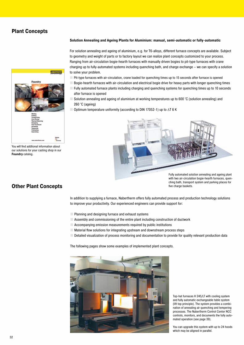
Top-hat furnaces H �45/LT with cooling system and fully automatic exchangeable table system (lift top principle). The system provides a combi-nation of annealing air quenching and tempering processes. The Nabertherm Control Center NCC controls, monitors, and documents the fully auto-mated operation (see page 39).
You can upgrade this system with up to �4 hoods which may be aligned in parallel.
In addition to supplying a furnace, Nabertherm offers fully automated process and production technology solutions to improve your productivity. Our experienced engineers can provide support for:
Planning and designing furnace and exhaust systemsAssembly and commissioning of the entire plant including construction of ductworkAccompanying emission measurements required by public institutionsMaterial flow solutions for integrating upstream and downstream process stepsDetailed visualization of process monitoring and documentation to provide for quality relevant production data
The following pages show some examples of implemented plant concepts.
Solution Annealing and Ageing Plants for Aluminium: manual, semi-automatic or fully-automatic
For solution annealing and ageing of aluminium, e.g. for T6-alloys, different furnace concepts are available. Subject to geometry and weight of parts or to factory layout we can realize plant concepts customized to your process. Ranging from air-circulation bogie-hearth furnaces with manually driven bogies to pit-type furnaces with crane charging up to fully-automated systems including quenching bath, and charge exchange – we can specify a solution to solve your problem.
Pit-type furnaces with air-circulation, crane loaded for quenching times up to 15 seconds after furnace is openedBogie-hearth furnaces with air-circulation and electrical bogie drive for heavy parts with longer quenching timesFully automated furnace plants including charging and quenching systems for quenching times up to 10 seconds after furnace is openedSolution annealing and ageing of aluminium at working temperatures up to 600 °C (solution annealing) and �60 °C (ageing)Optimum temperature uniformity (according to DIN 1705�-1) up to ΔT 6 K
Plant Concepts
Fully automated solution annealing and ageing plant with two air-circulation bogie-hearth furnaces, quen-ching bath, transport system and parking places for five charge baskets.
You will find addtional information about our solutions for your casting shop in our Foundry catalog.
3�

Fully automated Furnace Plant consisting of 8 x W 1280/70ASThis fully automated tempering plant consisting of 8 air circulation bogie hearth furnaces, two cooling stations and loading and unloading facilities, Nabertherm offers an ideal solution for many heat treatment processes. The loading and unloading stations buffer the continuous processes before and after the heat treatment system. If necessary, the plant can be equipped with exhaust gas treatment facilities including after burner systems.
After the operator has released the fully loaded bogie at the charging station, the system runs automatically without further operator intervention. The shuttle delivers the charge into the selected furnace. With the electro-hydraulic lifting doors closed, the heat treatment process starts. When the �4 hour long temperature program is finished, the charge is transferred into one of the two cooling stations, where it stays until a safe handling temperature is reached. The shuttle then transports the charge to the unloading facility. If the facility is occupied the charge will be stored on a buffer station until the unloading area is available. The Software Nabertherm Control Center (NCC) takes care of control, visualization and documentation.
The system shown below can be expanded or adapted in modular steps to meet your individual needs.
Unlo
adin
gLo
adin
g
Furnace 1 Furnace 4
Furnace 8 Cooling station
Furnace � Furnace 3
Furnace 7 Furnace 6 Furnace 5
Cooling station
33

Protective Gas Retort Furnaces with Indirect Heating Outside the Retort
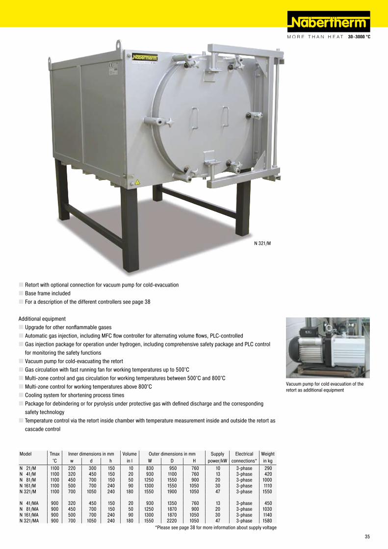
N 21/M - N 321/MAThese gas-tight retort furnaces with indirect heating outside the retort are particularly suitable for heat treatment requiring a constant defined protective gas or even reactive gas atmosphere in the furnace chamber. The working chamber consists of a gas-tight retort with water cooling in the door area to protect the special seal.
Depending on the temperature range to be applied in the furnace, we recommend different versions for optimizing the temperature distribution. The basic furnace alone attains a temperature uniformity of ΔT 30K at temperatures above 800°C according to DIN 1705�. Additional equipment can further optimize these furnaces for reaching a temperature uniformity of up to ΔT 10K in other temperature ranges as well:
For a working range up to approx. 500°C the furnace is equipped with gas circulation with a fast running fan in the door.Between 500°C and 800°C the heating should also be divided into three zones and controlled.Above 800°C, three-zone control without gas circulation is the proper version.
The basic furnace is prepared for operation with a nonflammable protective gas. Equipment is also available for operation with other gases up to safe operation under hydrogen. By optimizing with various additional equipment, i.e. with cascade control, you can customize the furnace for the particular process. A vacuum pump can be employed to cold-evacuate the furnace, among other purposes, for reducing the gas consumption during pre-purging.
Tmax 1100°CGas-tight retort for heat treatment in a constant defined atmosphereOperation with nonflammable protective gases including nitrogen, argon, forming gas (95/5)Open coolant system for the door sealRadiation protection plates for reducing the temperature drop at the doorAll-round heating of the retort for good temperature uniformityManual gas injection with stopcock, flow meter and control valve, with complete tubing
N �1/M with vacuum pump for cold-evacuating of the retort at ambient temperature
Radiation protection plates for reducing the temperature drop at the door
Gas circulation as additional equipment
34
N 3�1/M
Retort with optional connection for vacuum pump for cold-evacuationBase frame includedFor a description of the different controllers see page 38
Additional equipmentUpgrade for other nonflammable gasesAutomatic gas injection, including MFC flow controller for alternating volume flows, PLC-controlledGas injection package for operation under hydrogen, including comprehensive safety package and PLC control for monitoring the safety functionsVacuum pump for cold-evacuating the retortGas circulation with fast running fan for working temperatures up to 500°CMulti-zone control and gas circulation for working temperatures between 500°C and 800°CMulti-zone control for working temperatures above 800°CCooling system for shortening process timesPackage for debindering or for pyrolysis under protective gas with defined discharge and the corresponding safety technologyTemperature control via the retort inside chamber with temperature measurement inside and outside the retort as cascade control
Vacuum pump for cold evacuation of the retort as additional equipment
Model Tmax Inner dimensions in mm Volume Outer dimensions in mm Supply Electrical Weight°C w d h in l W D H power/kW connections* in kg
N �1/M 1100 ��0 300 150 10 830 950 760 10 3-phase �90N 41/M 1100 3�0 450 150 �0 930 1100 760 13 3-phase 4�0N 81/M 1100 450 700 150 50 1�50 1550 900 �0 3-phase 1000N 161/M 1100 500 700 �40 90 1300 1550 1050 30 3-phase 1110N 3�1/M 1100 700 1050 �40 180 1550 1900 1050 47 3-phase 1550
N 41/MA 900 3�0 450 150 �0 930 1350 760 13 3-phase 450N 81/MA 900 450 700 150 50 1�50 1870 900 �0 3-phase 1030N 161/MA 900 500 700 �40 90 1300 1870 1050 30 3-phase 1140N 3�1/MA 900 700 1050 �40 180 1550 ���0 1050 47 3-phase 1580
*Please see page 38 for more information about supply voltage
35

Annealing retort without gas circulation Annealing retort with gas circulation
Pit-Type Retort Furnaces with Gas Tight Retort, with or without Gas Circulation
S 100/R - S 1000/RAThese pit-type retort furnaces are particularly suitable for annealing of heavy charges or charge baskets handled by crane which require heat treatment under protective gas in a defined atmosphere. Just like the models N �1/M etc., these furnaces can be evacuated at ambient temperatures to reduce gas consumption during pre-purging. Alternatively, furnaces S 500/RA and larger are available with interior retort gas circulation to further improve temperature uniformity.
S 100/R - S 1000/RPit-type retort furnaces for heat treatment in a defined protective gas atmosphereMaximum temperatures of 1100 °CGas tight alloy retort with protective gas inlet and outletPort for temperature measurements in the chamberFor all non-flammable protective gases including nitrogen, argon, or forming gas 95/5Water-cooled lid with ‚O‘ ring sealingHeating from four sidesOptimum temperature uniformity (according to DIN 1705�-1) up to ΔT 14 KPneumatic or hydraulic lid liftingFor control system see page 38/39
Additional Equipment for Standard Models S 500/RA - R 1000/RAGas circulation with fan in the lid for optimum temperature uniformity according to DIN 1705�-1 up to ΔT 6 KWater-cooled motor flange
Additional EquipmentManual or automatic gas supply panelAutomatic exhaust damper and cooling fan for rapid coolingControl of retort temperature insideVacuum pump for evacuating the retort at ambient temperature prior to heat treatment for reduced pre-purge times and gas consumptionCooling station, additional retort for increased productivityCustom sizes up to 3,000 liters and charge weights up to 5,000 kgCharging baskets and devices
Model Tmax Inner dimensions annealing retort Volume Outer dimensions in mm Supply Electrical Weight°C Ø in mm h in mm in l W D H power/kW connections* in kg
S 100/R 1100 450 600 100 950 950 1�00 16 3-phase 800S �00/R 1100 600 800 �00 1�00 1�00 1400 �4 3-phase 1100S 300/R 1100 600 1000 300 1�00 1�00 1600 35 3-phase 1300S 500/R 1100 800 1000 500 1400 1400 1600 46 3-phase 1500S 600/R 1100 800 1�00 600 1400 1400 1800 54 3-phase 1600S 800/R 1100 1000 1000 800 1600 1600 1600 70 3-phase 1700S 1000/R 1100 1000 1300 1000 1600 1600 1900 90 3-phase 1900
S 500/RA 1100 800 1000 500 1400 1600 �400 46 3-phase 1500S 600/RA 1100 800 1�00 600 1400 1600 �600 5� 3-phase 1600S 800/RA 1100 1000 1000 800 1600 1800 �400 70 3-phase 1900S 1000/RA 1100 1000 1300 1000 1600 1800 �700 90 3-phase ��00
*Please see page 38 for more information about supply voltage
S 800/RA
S 600/R
36

Plants with catalytic and thermal Afterburning Systems
For exhaust air cleaning that may be required during powder metallurgical processes, drying, curing, debinding, and sintering processes, Nabertherm offers cleaning systems customized to the process. Catalytic systems for cracking organic compounds can be provided as well as thermal systems for higher exhaust volumes of organic waste gases.
Catalytic or thermal afterburning systems Customized size and design tailored to process conditionsCatalytic afterburner including electrical heater for heating up the exhaust air to the reaction temperatureSophisticated safety concepts for complex plants (e.g. protection against restarting if process is interrupted in critical segments, flooding the furnace chamber with nitrogen or air before restarting etc.)
Bogie hearth furnace system with integrated thermal afterburner for exhaust air cleaning and safety concept
Chamber furnace system with catalytic afterburner under construction
Process visualisation
37

H 100
B 180
P 330
C �90
B 150
C 40/C 4�
Process Control and Documentation
Nabertherm has more than 50 years of experience in design and construction of tailor-made switchgear and control systems. Our systems control the process, handling, documentation and other complex requirements. Our standard solutions take care of most applications. We can accommodate specific requirements, including using company-specified products or conforming to national or third-party standards.
Standard ControllersOur extensive line of standard controllers satisfies most customer requirements. Based on the specific furnace model, the controller regulates the furnace temperature reliably. The standard controllers are developed and fabricated within the Nabertherm group. When developing controllers, our focus is on ease of use. From a technical standpoint, these devices are custom-fit for each furnace model or the associated application. From the simple controller with an adjustable temperature to the control unit with freely configurable control parameters, stored programs, PID microprocessor control with self-diagnosis system and a computer interface, we have a solution to meet your requirements.
Mains voltages for Nabertherm furnaces1-phase: all furnaces are available for mains voltages from 110 V - �40 V at 50 or 60 Hz.3-phase: all furnaces are available for mains voltages from �00 V - �40 V or 380 V - 480 V, at 50 or 60 Hz.
Matching of Controllers to Furnace Families
Functionality of the Standard ControllersC �90 B 150 C 40 B 180 P 330 H 100
Number of programs 9 1 9 1 9 50Segments 40 � 18 � 40 99Extra functions (e.g. fan or autom. flaps) �² � � �Maximum number of control zones 1 1³ 1 1 3¹Graphic color display lStatus messages in clear text l l l l l lStart time configurable (e.g. to use night power rates) l l l l l l¹Operating hour counter l l l l lAuto tune l l l lProgram entry in steps of 1 °C or 1 min. l l l l l lSkip-button for segment jump l lDrive of manual zone regulation lInterface for MV software ¡ ¡ l ¡ lProgrammable power outlet lkWh meter l l l l lReal-time clock l l lBath control/charge control ¡
Data input via number pad l l l¹ Not for melt bath control² As an extra feature in ovens with air circulation³ Control of additional separate slave regulators possiblel Standard¡ Option
W(B
) 580
0/�6
..
W 1
000/
65 ..
S 30
/45A
..
S 10
0/A.
.
N 56
0/�6
A..
N 30
/45H
A..
N 15
/65S
HA..
N ..H
ACLS
TR 6
0..
W 1
000/
G..
N 7/
H..
N 31
/H..
N 81
/13.
.
WB
10..
TS �
0/15
..
D �0
/S..
N �1
/M..
S 10
0/R.
.
Page in catalog 4 6 8 9 10 1� 15 16 17 18 �0 �0 �0 �6 �7 �8 34 36
ControllerB 150 l l l l l l l l lC �90 l ¡ l ¡ ¡ ¡ l l ¡ ¡ ¡ ¡ ¡ lC 40B 180 lP 330 ¡
H 700 lH 1700 l ¡ ¡ ¡ ¡ ¡ ¡ ¡ ¡ ¡ ¡ l ¡ ¡
H 3700 ¡ ¡ ¡ ¡ ¡ ¡ ¡ ¡ ¡ ¡ ¡ ¡ ¡ ¡
38

Professional Control and Documentation Alternatives
H 3700 with colored graphic presentation of data
Control Center NCC user interface display-ed on a PC
H 1700 with colored, tabular depiction of the data
Graphic printer
HiProSystems Control and DocumentationThis professional control system for single and multi-zone furnaces is based on Siemens hardware and can be adapted and upgraded extensively. HiProSystems control is used when more than two process-dependent functions, such as exhaust dampers, cooling fans, automatic movements, etc., have to be handled during a cycle; when furnaces with more than one zone have to be controlled; when special documentation of each batch is required and when remote telediagnostic service is required. The system is also perfectly suited for controlling multiple furnaces or furnace groups. It is flexible and is easily tailored to your process or documentation needs.
Alternative User InterfacesTouch panel H 700This basic panel accommodates most basic needs and is very easy to use.Touch panel H 1700Firing cycle data and the extra functions activated are clearly displayed in a table. Messages appear as text.Touch panel H 3700All functions and process data are stored and displayed in easy to read charts. The data can be exported through various interfaces (RS �3�, RS 4�� /485, USB, Ethernet TCI/IP, MPI, Profibus) to a local PC or your company network for further processing. A CF card also gives the opportunity for data storage and transfer to a PC with a card reader.Extension Package, PC-based for Control, Visualisation and Documentation Nabertherm Control Center NCCUpgrading the HiProSystems-Control individually into an NCC provides for additional interfaces, operating documentation, and service benefits in particular for controlling furnace groups including charge beyond the furnace itself (quenching tank, cooling station etc.):
Recommended for heat treatment processes with extensive requirements in respect to documentation e.g. for metals, technical ceramics or in the medicine fieldSoftware can be used also in accordance with the AMS 2750 D (NADCAP)Documentation according to the requirements of Food and Drug Administration (FDA), Part 11, EGV 164�/03 possibleCharge data can be read in via barcodesInterface for connection to existing Enterprise Database systems (e.g. SAP, Oracle)Connection to mobile phone network for alarm message transmission via SMSControl from various locations over the networkCalibration of each measuring point for a specific temperature possibleExtendable for calibration of a polygonal line with up to 18 temperatures per measuring point for use at different temperatures e.g for AMS �750 D applications
Controltherm MV Software for Monitoring, Documentation and Control with Standard Con-trollersDocumentation and reproducibility gain increased attention with steadily rising quality standards.The powerful Nabertherm software Controltherm MV provides for an optimum solution for the control anddocumentation of one or more furnaces (furnace data only).
FeaturesSimple installation without specific knowledgeAll Nabertherm controllers with interface connectableTemperature cycles of up to 16 furnaces (also multi-zone controlled) can be archived in manipulation-safe filesRedundant storage on a network server possibleProgramming, archiving and printing of programs and graphicsFree input of descriptive charge data text with comfortable search functionData exportable into Excel format for further evaluationStart/stop of the controller from the local PC400 additional programs storable (only with Nabertherm controllers)Connection of other furnaces/controllers by means of an additional temperature transducer possible and retrofittableExtension of additional measuring points for archiving possible and retrofittable
*not possible in combination with temperature transducer
Temperature RecorderReliable documentation method with a dot printer or continuous pen and up to six measuring points, also availablewith digitally storing graphic printer (e.g. CF card, USB-stick).
39

Headquarters: Nabertherm GmbH · �8865 Lilienthal/Bremen, Germany · Tel +49 (4�98) 9��-0, Fax -101 · [email protected]
www.nabertherm.com
Reg-
Nr. C
4.1
/09.
08 (e
nglis
ch) I
nfor
mat
ion
here
in is
sub
ject
to c
hang
e wi
thou
t not
ice.
Nab
erth
erm
ass
umes
no
liabi
lity
for a
ny e
rrors
that
may
app
ear i
n th
is d
ocum
ent.
Please visit our website www.nabertherm.com and find out all you want to know about us and our products.
In addition to our current calendar of trade fairs and training dates, there is also the opportunity to get in touch directly with your local sales office or nearest dealer world-wide.
Professional Solutions for:Arts & CraftsGlassCeramicsLaboratory/DentalHeat Treatment of Metals, Plastics and Surface FinishingFoundry
The whole World of Nabertherm: www.nabertherm.com
[email protected]: (+49) 4�98 9��-0Fax: (+49) 4�98 9��-1�9
[email protected]: (+86) �1 6490 �960Fax: (+86) �1 6490 3107
[email protected]: (+33) 1 5356 1800Fax: (+33) 1 5356 1809
[email protected]: (+39) 348 38�0�78Fax: (+39) 055 480835
[email protected]: (+41) 6� �09 6070Fax: (+41) 6� �09 6071
[email protected]: (+44) 19�� 455 5�1Fax: (+44) 19�� 455 �77
[email protected]: (+1) 30� 3�� 3665Fax: (+1) 30� 3�� 3�15
[email protected].: (+34) 93 553 08 87Fax: (+34) 93 583 95 85
Sales and Service Subsidiaries:
Nabertherm GmbHBahnhofstr. �0�8865 Lilienthal, Germany
Nabertherm Shanghai Ltd.150 Lane, No. 158 Pingbei Road, Minhang District�01109 Shanghai, China
Nabertherm S.A.S51 Rue de Presles93531 Aubervilliers, France
Nabertherm Italiavia Trento N° 1750139 Florence, Italy
Nabertherm Schweiz AG Batterieweg 64614 Hägendorf, Switzerland
Nabertherm Ltd.Vigo Place, AldridgeWest Midlands WS9 8YB, United Kingdom
Nabertherm Inc.54 Reads WayNew Castle, DE 197�0, USA
Nabertherm Ibérica, S.L.Av. de les Corts Catalanes 9 - 11Despacho 4E - Entidad 1� - 1308173 Sant Cugat del Vallés (Barcelona), Spain