heating, ventilation & air conditioning units - autocontrol · serving the international oil...
TRANSCRIPT

SYSTEMS INTEGRATION AND PROCESS ENGINEERING
heating, ventilation &air conditioning units
English /
AC_CatHVAC_rv03@1-20#.indd 1AC_CatHVAC_rv03@1-20#.indd 1 14/10/14 14:4314/10/14 14:43

servingthe international oil& gas industry
ITALIAN TECHNOLOGY
HEATING, VENTILATION & AIR CONDITIONING UNITS (HVAC)The company is an active manufacturer of Heating, Ventilation & Air Conditioning units (HVAC) for installation in hazardous areas (refi neries, oil wells, off-shore platforms, etc.) dealing effectively with the most severe environmental conditions.More than ten years’ experience in the fi eld of system integration with the production of process analyzer shelters, has allowed us to create high quality and top performing HVAC units.Our wide range of HVAC systems allows us to meet the demands and needs of our customers. ATEX certifi cation of these systems makes our company a landmark for end users, top engineering companies and main contractors.
AUTOMATIC SAMPLINGThe company is an international leader in designing and manufacturing automatic sampling systems for crude oil and refi ned products.Automatic Sampling is an increasingly worthy activity when oil custody transfer takes place. The rising costs of raw materials, processing and disposal of pollutants have made a representative sample strategic because it represents the entire batch of oil in transit. Years of experience in the fi eld and unparalleled professionalism guarantee immediate returns on investments, as sampling becomes a means for cutting costs signifi cantly over time.Today, Autocontrol Technologies has supplied its customers with automatic sampling units throughout the world in oil terminals, production wells, off-shore platforms, tankers, refi neries and metering skids.The company is also a permanent member of the main international organisations (ISO, API) that regulate this strategic matter.
PROCESS CONTROL SYSTEMS INTEGRATIONThe company is largely involved in the system integration and process engineering for Oil & Gas applications, which includes the design and manufacturing of:- sample conditioning systems, recovery systems, calibration
systems for process analyzers.- analyzer shelters and cabinets for safe and hazardous areas
designed to integrate process analyzers and control automations.- on-line analyzers’ automation systems for continuous monitoring
of chemical/physical properties of process and environmental controls.
Autocontrol Technologies has supplied hundreds of systems to the main oil & gas companies worldwide.
Autocontrol Technologies was established in 1994 by its managing director, Roberto Scatizzi, in order to offer fresh solutions in the on-line instrumentation, process measurements and control automation fi elds, assisting the customer from design to installation with complete turn-key services.The company’s core business is engineering, construction and installation of high technology process instruments for the oil, petrochemical, chemical and power industries.The company is ISO 9001:2008 certifi ed and ATEX notifi ed for applications in hazardous areas.Autocontrol Technologies is organized in three main divisions:
2
ISO 9001:2008
AC_CatHVAC_rv03@1-20#.indd 2AC_CatHVAC_rv03@1-20#.indd 2 14/10/14 14:4314/10/14 14:43

3
CDX-CDACTX-CXX
HVAC units
CDA version
CDX version
The CDX – CDA – CTX and CXX series for Wall mounting and the same code with suffi x –R for series Roof mounting are Heating Ventilation Air Conditioner (HVAC units).
They are suitable either for Safe areas or for Zone 1 (or Zone 2) classifi ed areas (according to the EN 60079-10 standard) due to the presence of fl ammable gases or vapours (gas group IIA IIB IIB+H2 or IIC) or for Zone 21 (or Zone 22), in the presence of combustible dusts, according to the EN 61241-10 standard. These series are certified in compliance with 94/9/EC (ATEX) Directive, Group II, Category 2GD, protection by constructional safety according to EN 1127-1, EN 13463-1, EN 13463-5, EN 60079-14 and EN 61241-14 European standards and provided with:• EC Declaration of Conformity; • User’s Manual for installation, Operation and Maintenance.
Type examination certifi cate: ICEPI 10 ATEX 005
The models that we produce are suitable for the installation of the following apparatus:• TVR Analyzer Cabinet (Transportable Ventilated Rooms
according to EN 50381 standard);• TVR Analyzer Houses (Transportable Ventilated Rooms
according to EN 50381 standard);• Gas Metering stations;• Gas chromatograph stations;• Habitable Containers.
For aggressive environments the frames are built in 316L stainless steel materials.
AC_CatHVAC_rv03@1-20#.indd 3AC_CatHVAC_rv03@1-20#.indd 3 14/10/14 14:4314/10/14 14:43
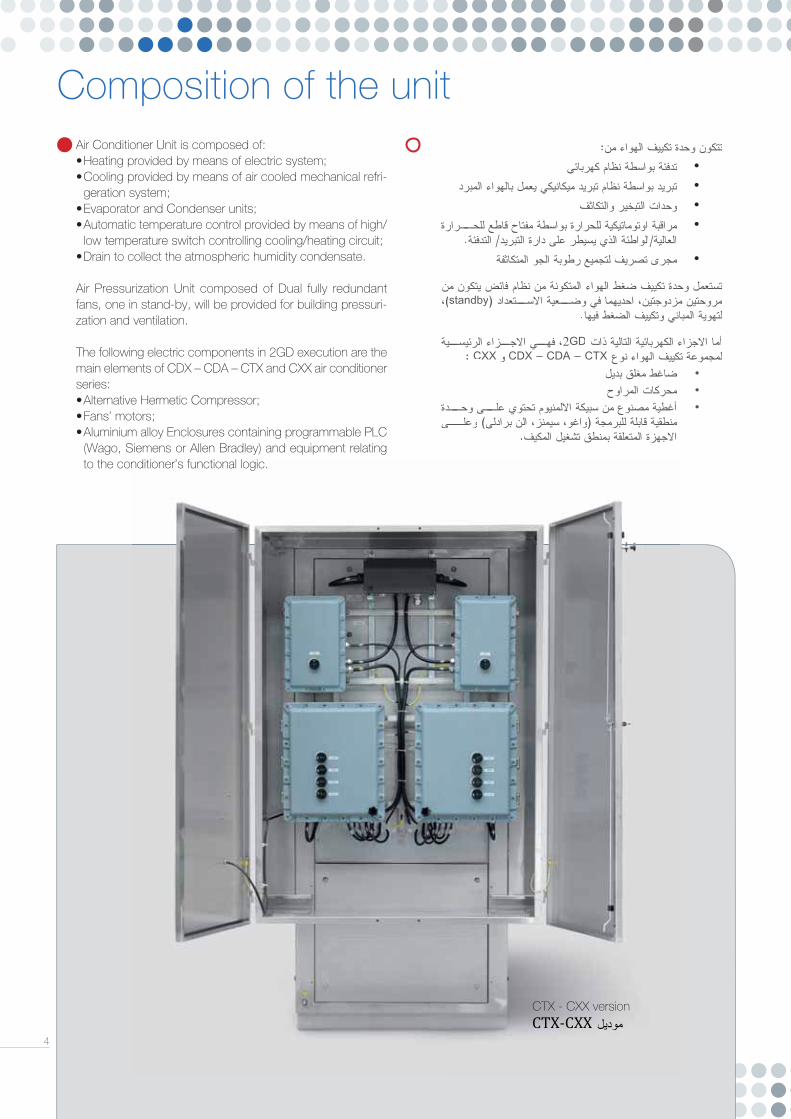
Composition of the unit
4
Air Conditioner Unit is composed of:• Heating provided by means of electric system;• Cooling provided by means of air cooled mechanical refri-
geration system;• Evaporator and Condenser units;• Automatic temperature control provided by means of high/
low temperature switch controlling cooling/heating circuit;• Drain to collect the atmospheric humidity condensate.
Air Pressurization Unit composed of Dual fully redundant fans, one in stand-by, will be provided for building pressuri-zation and ventilation.
The following electric components in 2GD execution are the main elements of CDX – CDA – CTX and CXX air conditioner series:• Alternative Hermetic Compressor;• Fans’ motors;• Aluminium alloy Enclosures containing programmable PLC
(Wago, Siemens or Allen Bradley) and equipment relating to the conditioner’s functional logic.
CTX - CXX version
AC_CatHVAC_rv03@1-20#.indd 4AC_CatHVAC_rv03@1-20#.indd 4 14/10/14 14:4314/10/14 14:43

5
CDX-CDACTX-CXX
HVAC units
CTX - CXX version
There are also the following non-electrical components (risks analysis already carried out): • Fans; • Air Refrigerant gas heat exchangers, finned battery type,
with copper tubing and aluminium fins; • Cooling circuit made of copper welded with precious alloy,
completed with: lamination capillary tube, mechanical dehydratation filter, brass valves, pressure and temperature control devices.
The HVAC units will be equipped with a Control Box, Power Box/es and a Box for the intrinsically safe barriers and they will be fully controlled by a PLC (Programmable Logic Control) and the alarms will be sent to Control Room by free contact relay.All the lamps and the control switches for the HVAC units status control / monitoring will be installed in front of the control box.
AUTOCONTROL TECHNOLOGIES, in these last years, has developed a Graphic Controller system for the HVAC units status control / monitoring.This system is composed of a graphic panel for the HVAC monitoring (alarms and status of the system) and a keyboard suitable for the control (Temperature setting).This system can be protected by password.
All the HVAC units can be built also for Safe Areas.
AC_CatHVAC_rv03@1-20#.indd 5AC_CatHVAC_rv03@1-20#.indd 5 14/10/14 14:4314/10/14 14:43

CDX - CDA HVAC units
CDX 2.5 to 4.0 kWAir conditioner units provided with a single refrigerant circuit can be equipped with one or two compressors, depending on the cooling capacity required, a single heating circuit and with two pressurization fans 100% redundant for the pressurization systems of the apparatus.This model of HVAC units can be built with out pressurization system for installation on the small Local Cabinet.
CDA 6.0 to 33.0 kWAir conditioner units provided with a single refrigerant circuit can be equipped with one or two compressors, depending on the cooling capacity required, a single heating circuit and with two pressurization fans 100% redundant for the pressurization systems of the apparatus.
6
REFRIGERANT CIRCUIT
1 Evaporator
2 Evaporator fan
3 Low pressure switch
4 High pressure switch
5 Condenser
6 Fan control pressure switches
7 Valve
8 Dryer fi lter
9 Liquid visual indicator
10 Refrigerant receiver
11 Expansion valve
12 Condenser fan
13 Compressor
14 Heating resistance
15 Pressurization fans
AC_CatHVAC_rv03@1-20#.indd 6AC_CatHVAC_rv03@1-20#.indd 6 14/10/14 14:4314/10/14 14:43

7
AERAULIC CIRCUIT
For the detail of heating and cooling capacities and fi ltration effi ciencies available, please see the Technical Data Sheets and contact Autocontrol Technologies for any specifi c request.
GD1 Gravity damper
GD2 Gravity damper
GD3 Gravity damper
GD4 Gravity damper
AF Air fi lter
HR Heating resistance
EF Evaporator fan
PF1 Pressurization fan
PF2 Pressurization fan
CF1,2,3 Condenser fan
DP1 Differential pressure-switch
DP2 Differential pressure-switch
DP3,4 Differential pressure-switch
AC_CatHVAC_rv03@1-20#.indd 7AC_CatHVAC_rv03@1-20#.indd 7 14/10/14 14:4314/10/14 14:43

REFRIGERANT CIRCUIT
CTX - CXX
1 Evaporator
2 Evaporator fans
3 Low pressure switches
4 High pressure switches
5 Condenser
6 Fans control pressure switches
7 Valves
8 Dryer fi lters
9 Liquid visual indicator
10 Refrigerant receivers
11 Expansion valves
12 Condenser fans
13 Compressors
14 Heating resistance
15 Pressurization fans
16 Capacity control valves
CTX 13.0 to 54.0kWAir conditioner units provided with double independent refrigerant circuits, 50% redundant. Can be equipped with one or two compressors per, depending on the cooling capacity required, double independent heating circuits, 50% redundant, and with two pressurization fans, 100% redundant, for the pressurization systems of the apparatus.
CXX 6.5 to 27.0kWAir conditioner units provided with double independent refrigerant circuits, 100% redundant. Can be equipped with one or two compressors per, depending on the cooling capacity required, double independent heating circuits, 100% redundant, and with two pressurization fans, 100% redundant, for the pressurization systems of the apparatus.
HVAC units
8
AC_CatHVAC_rv03@1-20#.indd 8AC_CatHVAC_rv03@1-20#.indd 8 14/10/14 14:4314/10/14 14:43

9
AERAULIC CIRCUIT
GD1 Gravity damper
GD2 Gravity damper
GD3 Gravity damper
GD4 Gravity damper
GD5 Gravity damper
GD6 Gravity damper
MD1 Manual damper
MD2 Manual damper
EF1 Evaporator fan
EF2 Evaporator fan
CF2 Condenser fan
CF1 Condenser fan
H1 Heating resistance
H2 Heating resistance
AF1 Air fi lter
AF2 Air fi lter
AF3 Air fi lter
DP1 Differential pressure-switch
DP2 Differential pressure-switch
DP3,4 Differential pressure-switches
For the detail of heating and cooling capacities and fi ltration effi ciencies available, please see the Technical Data Sheets and contact Autocontrol Technologies for any specifi c request.
AC_CatHVAC_rv03@1-20#.indd 9AC_CatHVAC_rv03@1-20#.indd 9 14/10/14 14:4314/10/14 14:43

MODEL CDX252 CDX402 CDA602 CDA802Cooling Capacity (L30L50) kW 2,5 4 6 8Heating Capacity kW 1,0 (2,0 and 3,0 optional) 1,0 (2,0 and 3,0 optional) 6 6 type Axial Axial Axial AxialRecirculating fan m^3/h-Pa 1800 - 20 / 1000 - 40 1800 - 20 / 1000 - 40 2400 - 25 / 1800 - 60 2400 - 25 / 1800 - 60 n° 1 1 1 1 type Axial Axial Axial AxialCondensing fan m^3/h-Pa 1800 - 20 / 1000 - 40 2500 - 40 / 1500 - 120 2400 - 25 / 1800 - 60 2400 - 25 / 1800 - 60 n° 1 1 1 2 type / Centrifugal Centrifugal CentrifugalPressurization fan m^3/h-Pa 0 600 - 100 / 300 - 350 600 - 100 / 300 - 350 600 - 100 / 300 - 350(optional) kW 0 0,18 0,18 0,18 n° 0 2 2 2Compressor n° 1 1 1 1Refrigerant fl uid type R134a R134a R134a R134aPower Supply V/Ph/Hz 230/1/50 400/3/50 400/3/50 400/3/50
Power consumption Heat. kW 1,1 1,5 6,5 6,5
Cool. kW 1,1 2,1 2,8 3,3Protection degree IP 54 54 54 54Hazardous area class Ex II2G IIA,B,B+H2,C T3 Ex II2G IIA,B,B+H2,C T3 Ex II2G IIA,B,B+H2,C T3 Ex II2G IIA,B,B+H2,C T3Noise level dB ≤62 int. / 72 ext. (@1m) ≤65 int. / 75 ext. (@1m) ≤72 int. / 85 ext. (@1m) ≤72 int. / 85 ext. (@1m)Frame/Housing material AISI304 AISI304 AISI304 AISI304 H mm 2000 2000 2200 2200
Dimensions W mm 650 650 1100 1100
L mm 550 550 + 400 700 + 320 700 + 320 kg 115 (without power board) 120 (without power board) 340 (without power board) 350 (without power board)
CDX-CDA
CTX-CXX
10
MODEL CXX652 - CTX133 CXX802 - CTX163 CXX103 - CTX203 CXX123 - CTX243Circuit side A B A B A B A BCooling Capacity (L30L50) kW 6,5 6,5 8 8 10 10 12 12Heating Capacity kW 5 5 5 5 5 5 5 5
Recirculating fantype Axial Axial Axial Axial
m^3/h-Pa 2800 - 20 / 1300 - 60 4000 - 50 / 2500 - 90 4000 - 50 / 2500 - 90 4000 - 50 / 2500 - 90n° 1 1 1 1 1 1 1 1
Condensing fantype Axial Axial Axial Axial
m^3/h-Pa 4900 - 40 / 3000 - 90 4900 - 40 / 3000 - 90 4900 - 40 / 3000 - 90 4900 - 40 / 3000 - 90n° 1 1 1 1 1 1 2 2
Pressurization fan
type Centrifugal Centrifugal Centrifugal Centrifugalm^3/h-Pa 1200 – 350 / 800 – 600 1200 – 350 / 800 – 600 1200 – 350 / 800 – 600 1200 – 350 / 800 – 600
n° 2 2 2 2mod. MN502 MN502 MN502 MN502
Compressor n° 1 1 1 1 1 1 1 1Refrigerant fl uid type R134a R134a R134a R134aPower Supply V/Ph/Hz 415/3/50 415/3/50 415/3/50 415/3/50Power consumption CXX (redundancy 100%)
Cool. kW 3,6 4,1 4,7 5,3Heat. kW 5,9 6,0 6,0 6,0
Power consumption CTX (redundancy 50%)
Cool. kW 6,4 7,4 8,6 9,9Heat. kW 11,1 11,3 11,2 11,2
Protection degree IP 54 54 54 54Hazardous area class Ex II2G IIA,B,B+H2,C T3 Ex II2G IIA,B,B+H2,C T3 Ex II2G IIA,B,B+H2,C T3 Ex II2G IIA,B,B+H2,C T3Noise level dB ≤70 int. / 80 ext. (@1m) ≤70 int. / 80 ext. (@1m) ≤70 int. / 80 ext. (@1m) ≤70 int. / 80 ext. (@1m)Frame/Housing material AISI304 AISI304 AISI304 AISI304
Dimensions
H mm 2500 2500 2500 2500W mm 1100 1100 1100 1100L mm 1700 1700 1700 1700
kg 900 (without power board) 900 (without power board) 900 (without power board) 1000 (without power board)
AC_CatHVAC_rv03@1-20#.indd 10AC_CatHVAC_rv03@1-20#.indd 10 14/10/14 14:4314/10/14 14:43

11
CDA123 CDA153 CDA203 CDA263 CDA333 12 15 20 26 33 6 9 9 9 9 Axial Axial Axial Axial Axial 2400 - 25 / 1800 - 60 2400 - 25 / 1800 - 60 2400 - 25 / 1800 - 60 7000 - 40 / 5200 - 140 7000 - 40 / 5200 - 140 1 2 2 1 1 Axial Axial Axial Axial Axial 2400 - 25 / 1800 - 60 2400 - 25 / 1800 - 60 2400 - 25 / 1800 - 60 7000 - 40 / 5200 - 140 8400 - 40 / 6300 - 140 2 3 3 2 2 Centrifugal Centrifugal Centrifugal Centrifugal Centrifugal 600 - 100 / 300 - 350 800– 250 / 200 - 450 800– 250 / 200 - 450 800– 250 / 200 - 450 800– 250 / 200 - 450 0,18 0,25 0,25 0,25 0,25 2 2 2 2 2 1 1 1 1 2 R134a R134a R134a R134a R134a 400/3/50 400/3/50 400/3/50 400/3/50 400/3/50 6,5 9,7 9,7 10,3 10,3 4,2 5,8 7,3 11,3 14,5 54 54 54 54 54 Ex II2G IIA,B,B+H2,C T3 Ex II2G IIA,B,B+H2,C T3 Ex II2G IIA,B,B+H2,C T3 Ex II2G IIA,B,B+H2,C T3 Ex II2G IIA,B,B+H2,C T3 ≤72 int. / 85 ext. (@1m) ≤72 int. / 85 ext. (@1m) ≤72 int. / 85 ext. (@1m) ≤72 int. / 85 ext. (@1m) ≤72 int. / 85 ext. (@1m) AISI304 AISI304 AISI304 AISI304 AISI304 2200 2400 2400 2700 2700 1100 1350 1350 1350 1350 700 + 320 700 + 320 700 + 320 1200 + 320 1200 + 320 350 (without power board) 450 (without power board) 450 (without power board) 550 (without power board) 550 (without power board)
OPERATING LIMITSInternal ambient range °C +20 / +40External ambient range °C -40 / +55 (*)
(*) Till -40°C Only Heating mode
CXX143 - CTX283 CXX163 - CTX323 CXX193 - CTX383 CXX233 - CTX463 CXX273 - CTX543 CXX343 - CTX683A B A B A B A B A B A B14 14 16 16 19 19 23 23 27 27 34 345 5 5 5 7 7 7 7 7 7 7 7
Axial Axial Axial Axial Axial Axial4000 - 50 / 2500 - 90 4000 - 50 / 2500 - 90 4900 - 40 / 3000 - 90 4900 - 40 / 3000 - 90 4900 - 40 / 3000 - 90 6900 - 40 / 5200 - 140
1 1 1 1 1 1 1 1 1 1 1 1Axial Axial Axial Axial Axial Axial
4900 - 40 / 3000 - 90 4900 - 40 / 3000 - 90 6900 - 40 / 5200 - 140 6900 - 40 / 5200 - 140 6900 - 40 / 5200 - 140 6900 - 40 / 5200 - 1402 2 2 2 2 2 2 2 2 2 2 2
Centrifugal Centrifugal Centrifugal Centrifugal Centrifugal Centrifugal1200 – 350 / 800 – 600 1200 – 350 / 800 – 600 2800 – 400 / 1200 – 1100 2800 – 400 / 1200 – 1100 2800 – 400 / 1200 – 1100 2800 – 400 / 1200 – 1100
2 2 2 2 2 2MN502 MN502 MN602 MN602 MN602 MN602
1 1 1 1 1 1 1 1 1 1 2 2R134a R134a R134a R134a R134a R134a
415/3/50 415/3/50 415/3/50 415/3/50 415/3/50 415/3/506,0 6,5 10,4 10,9 12,6 15,56,0 6,0 9,6 9,6 9,6 10,011,3 12,3 18,5 19,5 22,9 28,711,2 11,2 16,9 16,9 16,9 17,754 54 54 54 54 54
Ex II2G IIA,B,B+H2,C T3 Ex II2G IIA,B,B+H2,C T3 Ex II2G IIA,B,B+H2,C T3 Ex II2G IIA,B,B+H2,C T3 Ex II2G IIA,B,B+H2,C T3 Ex II2G IIA,B,B+H2,C T3≤70 int. / 80 ext. (@1m) ≤70 int. / 80 ext. (@1m) ≤72 int. / 85 ext. (@1m) ≤72 int. / 85 ext. (1@m) ≤72 int. / 85 ext. (@1m) ≤72 int. / 85 ext. (@1m)
AISI304 AISI304 AISI304 AISI304 AISI304 AISI3042500 2500 2500 2500 2500 25001100 1100 1600 1600 1600 16001700 1700 2000 2000 2000 2000
1000 (without power board) 1000 (without power board) 1200 (without power board) 1200 (without power board) 1200 (without power board) 1350 (without power board)
AC_CatHVAC_rv03@1-20#.indd 11AC_CatHVAC_rv03@1-20#.indd 11 14/10/14 14:4314/10/14 14:43

MAC-CWXMAC-CRX
The MAC-CWX series air conditioners (for semi-fl ush wall mounting) and MAC-CRX series (for roof mounting) are air condensed monoblock units. They are suitable either for Zone 1 (or Zone 2) classifi ed areas (according to EN 60079-10 standard) due to the presence of fl ammable gases or vapors (gas group IIB/C) or for Zone 21 (or Zone 22), in presence of combustible dusts, according to EN 61241-10 standard.These series are certifi ed in compliance with 94/9/EC (ATEX) Directive, Group II, Category 2GD, protection by constructional safety “c”, according to EN 1127-1, EN 13463-1, EN 13463-5, EN 60079-14 and EN 61241-14 european standards.(Type examination certifi cate: ICEPI 08 ATEX 007)Every unit will be marked as II 2GD c IIB/C T5/4 T 100/135°C, and provided with:• EC Declaration of Conformity• User’s Manual for Installation, Operation and Maintenance.
These series can be designed only for the cooling activity (basic execution), or also for conditioning (heat pump execution) of the following apparatus:• Panel Boards containing electrical and electronic equipments;• Analysis Cabinets;• Operator Cabins for cranes and bridge cranes;• Elevator Cabins;• Habitable Containers.
12
Mac-Cwx version
MAC-CWX )
( MAC-CRX ) ( .
1 ) 2 ( EN 60079-10
IIB/C 21 ) 22 ( EN 61241-10
.
94/9/EC )( 2GD “c”
EN-1127-1 EN 13463-1 EN 13463-5 EN 61241-14.
) ICEPI 08 ATEX 007 .(
II 2GD c IIB/C T5/4 T 100/135°C :
• •
) ( ) (
: • • • • • .
AC_CatHVAC_rv03@1-20#.indd 12AC_CatHVAC_rv03@1-20#.indd 12 14/10/14 14:4314/10/14 14:43

" " "."
" "" "
IP65.
.
MAC-CWX/CRX 2GD .
• MCE • • MEV •
:
• •
• .
:
MAC-CWX/CRX
)HVAC ( )TVR( ) EN 50381(.
.
13
These latter will be mounted diametrically opposed on a stainless steel panel completed with through fi xing holes and suitable gasket, in order to maintain the IP65 degree of protection. The evaporator module is oriented towards internal environment in order to decrease relevent temperature; while condenser module, oriented toward the outside, will dissipate the heat.The following electric components in 2GD execution (with their own certifi cation) are main elements of MAC-CWX and MAC-CRX air conditioners:• Alternative Hermetic Compressor, our series MCE;• Fans’ motors;• Solenoid Valve of reversal device, our series MEV;• Aluminium alloy Enclosure containing equipments relating to
the conditioner’s functional logic.There are also the following non-electrical components (risks analysis carried out):
• Fans;• Air/Refrigerant gas heat exchangers, fi nned battery type,
with copper tubing and aluminuim fi ns;• Cooling circuit made of copper welded with precious alloy,
completed with: lamination capillary tube, mechanical deidratation fi lter, brass valves, pressure and temperature control devices.
The MAC-CWX/CRX series air conditioners can be combined with a separated group of fans, in order to form a HVAC system for cabinets and TVR (Transportable Ventilated Rooms, according to EN 50381 standard). The evaporator module can be provided with a commutation device for fan speed.
Mac-Crx montaggio a soffi tto.
AC_CatHVAC_rv03@1-20#.indd 13AC_CatHVAC_rv03@1-20#.indd 13 14/10/14 14:4314/10/14 14:43

REFRIGERANT CIRCUIT
MODEL MAC-CWX302YN MAC-CWX302YNH MAC-CWX402GN MAC-CWX402GNH MAC-CRX302YN MAC-CRX302YNH MAC-CRX402GN MAC-CRX402GNHCooling capacity L35L35/L35L50 - DINHeating capacityInput power Rated voltageCompressor motor power
Evaporator axial fan
Condenser axial fan
4-way reversing solenoid valveExchangers materialRefrigerant gasDegree of Protection Noise levelDimensionsHeight LengthWidth Depth Weight WORKING LIMITS Ambient temp. limitsAmbient humidity limits Operating cabinet or board internal temperature limits
1 compressor
2 evaporating exchanger
3 condensing exchanger
4 refrigerant fi lter
5 lamination capillary tube
6 compressor head limit thermostat
14
MAC-CWX MAC-CRX
Basic execution
Heat pump execution
Wbtu/h
WW
V/Ph/HzW
m3/hW
bladem3/h
Wblade
dB
mmmmmmmmkg
Min./Max.Min./Max.Min./Max.
3100/275010580/9385
/1350
230/1/501100700
120 4p 250 mm – 27°
1100120 4p
300 mm - 36°Not
Copper/alum.R134 aIP 65 67
-20 / 50 °C0 / 98% UR20 / 35 °C
W 1140
505560
R 4001146550
3100/275010580/9385
22001350
230/1/501100700
120 4p 250 mm – 27°
1100120 4p
300 mm - 36°Yes
Copper/alum.R134 aIP 65 67
-20 / 50 °C0 / 98% UR20 / 35 °C
3750/325012800/11100
/1550
230/1/501300700
120 4p 250 mm – 27°
1100120 4p
300 mm - 36°Not
Copper/alum.R407 cIP 65 67
-20 / 50 °C0 / 98% UR20 / 35 °C
3750/325012800/11100
30001550
230/1/501300700
120 4p 250 mm – 27°
1100120 4p
300 mm - 36°Yes
Copper/alum.R407 cIP 65 67
-20 / 50 °C0 / 98% UR20 / 35 °C
R 4001146550
R 4001146550
R 4001146550
W 1140
505560
W 1140
505560
W 1140
505560
75 ÷ 80
7 compression safety thermostat
8 external fan control pressure switch
9 refrigerant high pressure switch
10 refrigerant low pressure switch 1
11 refrigerant low pressure switch 2
12 four-way reversal solenoid valve
AC_CatHVAC_rv03@1-20#.indd 14AC_CatHVAC_rv03@1-20#.indd 14 14/10/14 14:4314/10/14 14:43

15
Dimensions (mm)
MAC-CWX
AC_CatHVAC_rv03@1-20#.indd 15AC_CatHVAC_rv03@1-20#.indd 15 14/10/14 14:4314/10/14 14:43

Dimensions (mm)
16
MAC-CWX MAC-CRX
MAC-CRX
AC_CatHVAC_rv03@1-20#.indd 16AC_CatHVAC_rv03@1-20#.indd 16 14/10/14 14:4314/10/14 14:43

17
HVAC’s ATEX certifi cate
AC_CatHVAC_rv03@1-20#.indd 17AC_CatHVAC_rv03@1-20#.indd 17 14/10/14 14:4314/10/14 14:43

18
Certifi cates
AC_CatHVAC_rv03@17-20#.indd 18AC_CatHVAC_rv03@17-20#.indd 18 21/04/15 18:1321/04/15 18:13
www.autocontrol.it
AC_CatHVAC_rv03@1-20#.indd 19AC_CatHVAC_rv03@1-20#.indd 19 14/10/14 14:4314/10/14 14:43

gfs
tudi
o.co
m04
/201
5-05
AUTOCONTROL TECHNOLOGIES S.r.l.Via B. Signorelli, 16 - 24066 Pedrengo (Bergamo) - Italy -Tel. +39 035 3235811 - Fax +39 035 3235891
[email protected] - www.autocontrol.it
AC_CatHVAC_rv03@17-20#.indd 20AC_CatHVAC_rv03@17-20#.indd 20 21/04/15 18:1421/04/15 18:14