heavy duty service manual md - conmet€¦ · components other than the drum should be obtained...
TRANSCRIPT
Standard CastBrake Drums
CastLite®
Brake Drums
TruTurn®
Brake Drums
Service Manual For Steer, Drive and Trailer Brake Drums
HDHEAVY DUTY
For All ConMet Brake Drums
MDMEDIUM DUTY
ABOUT THIS MANUALAbout This Manual
� Read this manual carefully, providing extra attention to its explanations and instructions.
� To ensure safe, continuous, trouble-free operation, understand your wheel hub system, and keep all components in proper operating condition.
� Information relating to brake shoes, S-cams, or other brake system components is not included in this manual. Information regarding brake-related components other than the drum should be obtained from the vehicle or component manufacturer's published service information.
� Additional information pertaining to servicing ConMet wheel hub assemblies can be found in ConMet Service Manual 10041406 (Service Manual for Steer, Drive & Trailer Hub Assemblies).
� Pay particular attention to all NOTES, CAUTIONS, WARNINGS, and DANGERS to avoid the risk of personal injury or property damage, and realize these statements are not exhaustive. ConMet cannot possibly know or evaluate all conceivable methods in which service may be performed or the possibly hazardous consequences of each method. Accordingly, those who use a procedure not recommended by ConMet must first satisfy themselves that neither their safety nor the safety of the product will be jeopardized by the service method selected.
Before You Begin
1. Read and understand all instructions and procedures before you begin to service drums.
2. Read and observe all Warning and Caution hazard alert messages in this publication. They provide information that can help prevent serious personal injury, damage to components, or both.
3. Follow your companyʼs maintenance and service, installation, and diagnostics guidelines.
4. Use special tools when required to help avoid serious personal injury and damage to components.
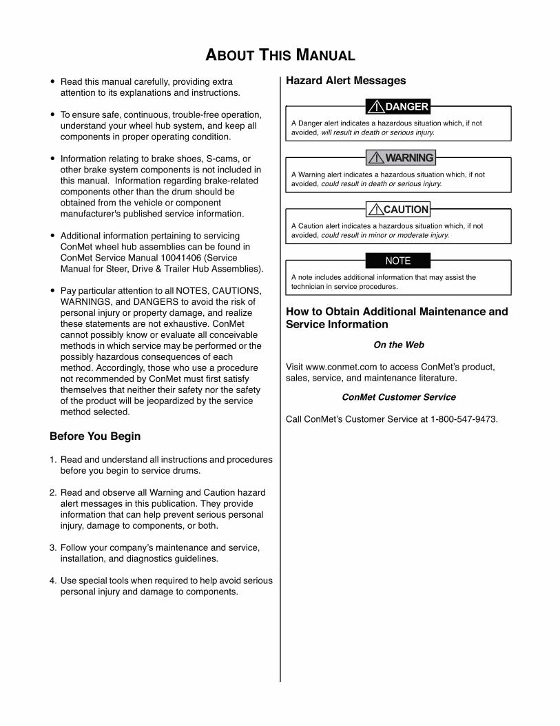
Hazard Alert Messages
WARNING
How to Obtain Additional Maintenance and Service Information
On the Web
Visit www.conmet.com to access ConMetʼs product, sales, service, and maintenance literature.
ConMet Customer Service
Call ConMetʼs Customer Service at 1-800-547-9473.
A Danger alert indicates a hazardous situation which, if not avoided, will result in death or serious injury.
A Warning alert indicates a hazardous situation which, if not avoided, could result in death or serious injury.
A Caution alert indicates a hazardous situation which, if not avoided, could result in minor or moderate injury.
A note includes additional information that may assist the technician in service procedures.
TABLE OF CONTENTSTable of Contents
1. INTRODUCTION ................................................................................................................................ 1Standard Cast Brake Drums ........................................................................................................ 1CastLite® Brake Drums ................................................................................................................ 1TruTurn® Brake Drums ................................................................................................................ 1
2. IDENTIFICATION ............................................................................................................................... 2WHEEL MOUNTING SYSTEMS ........................................................................................................ 2
Hub Pilot Wheel Mounting .............................................................................................................. 2Ball Seat Wheel Mounting System .................................................................................................. 2
IDENTIFYING CONMET HUB ASSEMBLIES .................................................................................... 2Vehicle Identification Number (VIN) ................................................................................................ 2ConMet Identifying Mark ................................................................................................................. 2ConMet Part Number ...................................................................................................................... 2Date Code ....................................................................................................................................... 3
3. BRAKE DRUM REMOVAL ................................................................................................................ 4HAZARD ALERT MESSAGES ........................................................................................................... 4
4. INSPECTION ...................................................................................................................................... 5BRAKE DRUM INSPECTION ............................................................................................................. 5
Heat Checks ................................................................................................................................... 5Cracked Drum (Barrel) .................................................................................................................... 5Cracked Drum (Mounting Flange) ................................................................................................... 6Blue Drum ....................................................................................................................................... 6Polished Drum ................................................................................................................................ 7Martensite Spotted Drum ................................................................................................................ 7Grease/Oil-Stained Drum ................................................................................................................ 7Scored (Grooved) Drum .................................................................................................................. 8Oversize (Worn) Drum .................................................................................................................... 8Out-of-Round Drum ........................................................................................................................ 8Drum Resurfacing ......................................................................................................................... 10
5. BRAKE DRUM REPLACEMENT ..................................................................................................... 11SELECTION OF NEW BRAKE DRUMS ........................................................................................... 11
6. ADDITIONAL INFORMATION ......................................................................................................... 12BRAKE DRUM BALANCE ................................................................................................................ 12
Balance Cut in Squealer Band ...................................................................................................... 12Turned-to-Balance ........................................................................................................................ 12
BRAKE DRUM STORAGE AND HANDLING ................................................................................... 12WHEEL STUD HOLES ..................................................................................................................... 13
Cast Stud Holes ............................................................................................................................ 13Large Diameter Stud Holes in Front Drums .................................................................................. 13Stud Hole Misconceptions ............................................................................................................ 14
7. BRAKE DRUM AND WHEEL INSTALLATION ............................................................................... 15Hub Pilot Wheel Mounting System ............................................................................................... 15Ball Seat Wheel Mounting System ................................................................................................ 16
WHEEL TORQUE SPECIFICATIONS .................................................................................................. 19
1. INTRODUCTION
Consolidated Metco, Inc. 1
5Introduction
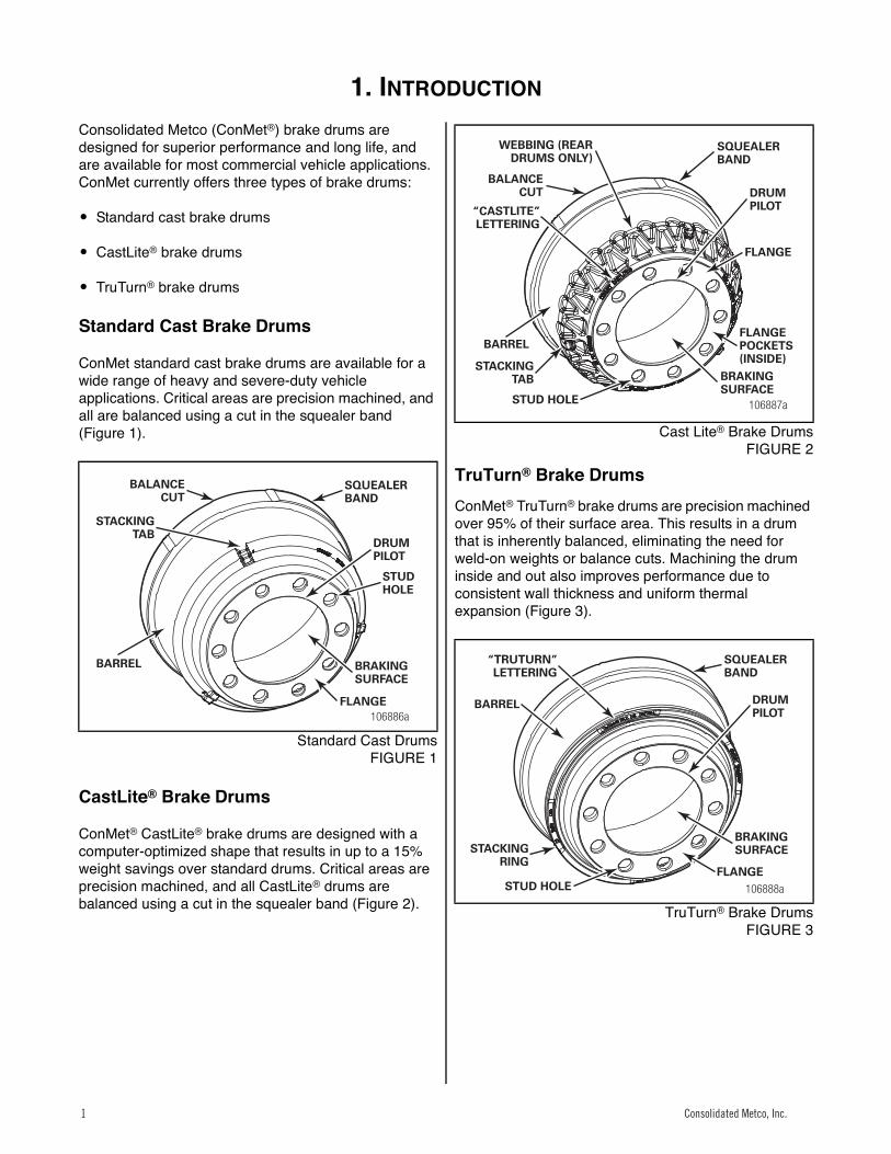
Consolidated Metco (ConMet®) brake drums are designed for superior performance and long life, and are available for most commercial vehicle applications. ConMet currently offers three types of brake drums:
� Standard cast brake drums
� CastLite® brake drums
� TruTurn® brake drums
Standard Cast Brake Drums
ConMet standard cast brake drums are available for a wide range of heavy and severe-duty vehicle applications. Critical areas are precision machined, and all are balanced using a cut in the squealer band (Figure 1).1
Standard Cast DrumsFIGURE 1
CastLite® Brake Drums
ConMet® CastLite® brake drums are designed with a computer-optimized shape that results in up to a 15% weight savings over standard drums. Critical areas are precision machined, and all CastLite® drums are balanced using a cut in the squealer band (Figure 2).
1
Cast Lite® Brake DrumsFIGURE 2
TruTurn® Brake DrumsConMet® TruTurn® brake drums are precision machined over 95% of their surface area. This results in a drum that is inherently balanced, eliminating the need for weld-on weights or balance cuts. Machining the drum inside and out also improves performance due to consistent wall thickness and uniform thermal expansion (Figure 3).2
TruTurn® Brake DrumsFIGURE 3
106886a
BALANCECUT
STACKINGTAB
BARREL
SQUEALERBAND
DRUMPILOT
STUDHOLE
BRAKINGSURFACE
FLANGE
106887a
WEBBING (REARDRUMS ONLY)
BALANCECUT
“CASTLITE”LETTERING
BARREL
STACKINGTAB
STUD HOLE
SQUEALERBAND
DRUMPILOT
FLANGE
BRAKINGSURFACE
FLANGEPOCKETS(INSIDE)
106888a
DRUMPILOT
SQUEALERBAND
BRAKINGSURFACE
FLANGESTUD HOLE
STACKINGRING
BARREL
“TRUTURN”LETTERING
Consolidated Metco, Inc.1
2. IDENTIFICATION
2 Consolidated Metco, Inc.
Identification
WHEEL MOUNTING SYSTEMS
Most ConMet brake drums can be used with both hub pilot and ball seat nut configurations.
Hub Pilot Wheel Mounting
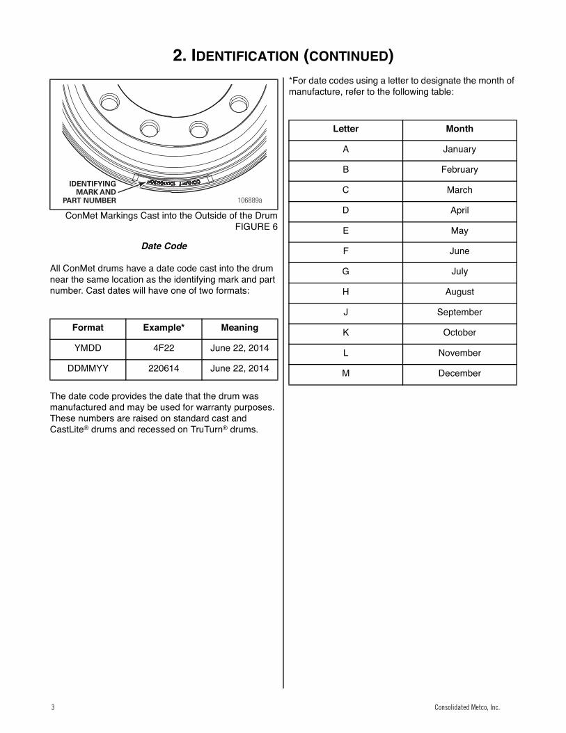
The hub pilot wheel mounting system makes use of a single two-piece flange nut on each wheel stud for both single and dual wheel applications (Figure 4). The hub pilot wheel mounting system is also known as the Uni-Mount-10™ (10 stud), WHD-10™ (10 stud), WHD-8™ (8 stud), and ISO system.
All ConMet brake drums have been designed to be compatible with hub pilot wheel mounting systems. There is no need to confirm stud hole size if fitting a ConMet drum to a hub pilot mounting system.3
Hub Pilot Mounting SystemsFIGURE 4
Ball Seat Wheel Mounting System
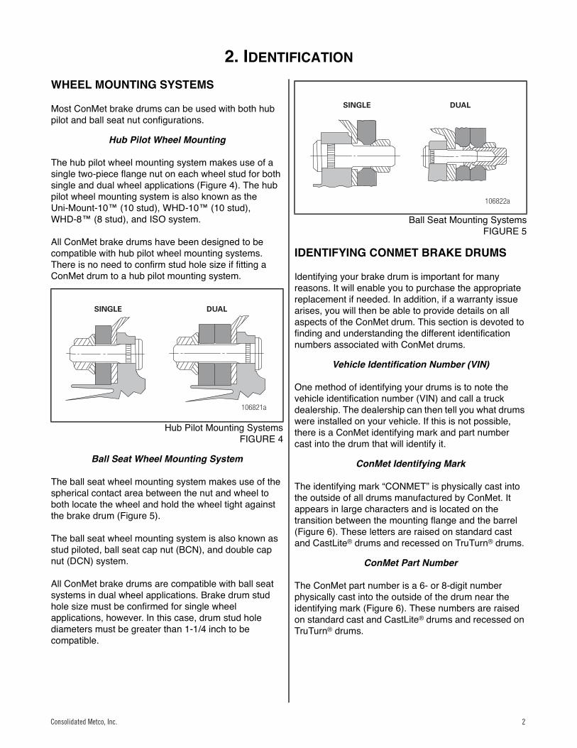
The ball seat wheel mounting system makes use of the spherical contact area between the nut and wheel to both locate the wheel and hold the wheel tight against the brake drum (Figure 5).
The ball seat wheel mounting system is also known as stud piloted, ball seat cap nut (BCN), and double cap nut (DCN) system.
All ConMet brake drums are compatible with ball seat systems in dual wheel applications. Brake drum stud hole size must be confirmed for single wheel applications, however. In this case, drum stud hole diameters must be greater than 1-1/4 inch to be compatible.
4
Ball Seat Mounting SystemsFIGURE 5
IDENTIFYING CONMET BRAKE DRUMS
Identifying your brake drum is important for many reasons. It will enable you to purchase the appropriate replacement if needed. In addition, if a warranty issue arises, you will then be able to provide details on all aspects of the ConMet drum. This section is devoted to finding and understanding the different identification numbers associated with ConMet drums.
Vehicle Identification Number (VIN)
One method of identifying your drums is to note the vehicle identification number (VIN) and call a truck dealership. The dealership can then tell you what drums were installed on your vehicle. If this is not possible, there is a ConMet identifying mark and part number cast into the drum that will identify it.
ConMet Identifying Mark
The identifying mark “CONMET” is physically cast into the outside of all drums manufactured by ConMet. It appears in large characters and is located on the transition between the mounting flange and the barrel (Figure 6). These letters are raised on standard cast and CastLite® drums and recessed on TruTurn® drums.
ConMet Part Number
The ConMet part number is a 6- or 8-digit number physically cast into the outside of the drum near the identifying mark (Figure 6). These numbers are raised on standard cast and CastLite® drums and recessed on TruTurn® drums.
106821a
SINGLE DUAL
106822a
SINGLE DUAL
Consolidated Metco, Inc. 2
2. IDENTIFICATION (CONTINUED)
3 Consolidated Metco, Inc.
5
ConMet Markings Cast into the Outside of the DrumFIGURE 6
Date Code
All ConMet drums have a date code cast into the drum near the same location as the identifying mark and part number. Cast dates will have one of two formats:
The date code provides the date that the drum was manufactured and may be used for warranty purposes. These numbers are raised on standard cast and CastLite® drums and recessed on TruTurn® drums.
*For date codes using a letter to designate the month of manufacture, refer to the following table:
Format Example* Meaning
YMDD 4F22 June 22, 2014
DDMMYY 220614 June 22, 2014
106889a
IDENTIFYINGMARK AND
PART NUMBER
Letter Month
A January
B February
C March
D April
E May
F June
G July
H August
J September
K October
L November
M December
Consolidated Metco, Inc.3
3. BRAKE DRUM REMOVAL
4 Consolidated Metco, Inc.
Brake Drum Removal
HAZARD ALERT MESSAGESRead and observe all Warning and Caution hazard alert messages in this publication. They provide information that can help prevent serious personal injury, damage to components, or both.
WARNING
1. Park the vehicle on a level surface. Block the wheels to prevent the vehicle from moving.
2. Raise the axle until the tires are off the floor.
3. Place safety stands under the trailer frame or under each axle spring seat. (Figure 7).
Figure 0.1
6
FIGURE 7
4. Remove the tire and wheel assembly using procedures specified by the wheel manufacturer.
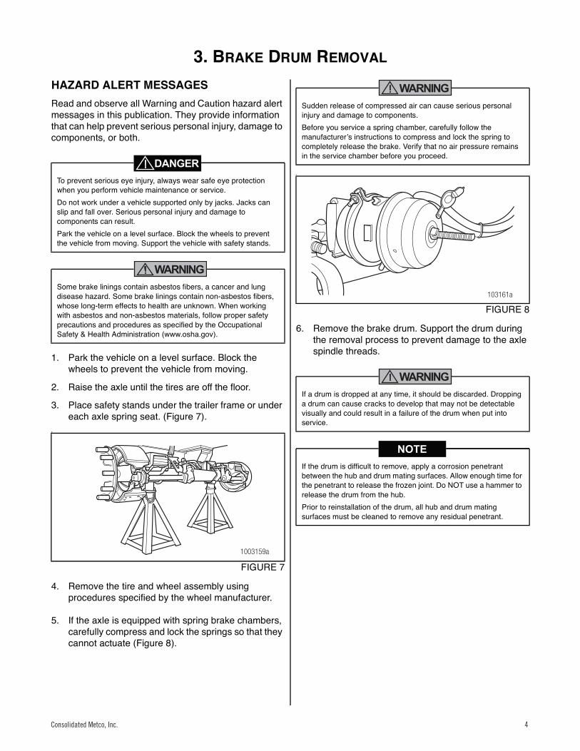
5. If the axle is equipped with spring brake chambers, carefully compress and lock the springs so that they cannot actuate (Figure 8).
WARNING
Figure 0.2
7
FIGURE 8
6. Remove the brake drum. Support the drum during the removal process to prevent damage to the axle spindle threads.
WARNING
To prevent serious eye injury, always wear safe eye protection when you perform vehicle maintenance or service.Do not work under a vehicle supported only by jacks. Jacks can slip and fall over. Serious personal injury and damage to components can result.Park the vehicle on a level surface. Block the wheels to prevent the vehicle from moving. Support the vehicle with safety stands.
Some brake linings contain asbestos fibers, a cancer and lung disease hazard. Some brake linings contain non-asbestos fibers, whose long-term effects to health are unknown. When working with asbestos and non-asbestos materials, follow proper safety precautions and procedures as specified by the Occupational Safety & Health Administration (www.osha.gov).
1003159a
Sudden release of compressed air can cause serious personal injury and damage to components.Before you service a spring chamber, carefully follow the manufacturerʼs instructions to compress and lock the spring to completely release the brake. Verify that no air pressure remains in the service chamber before you proceed.
If a drum is dropped at any time, it should be discarded. Dropping a drum can cause cracks to develop that may not be detectable visually and could result in a failure of the drum when put into service.
If the drum is difficult to remove, apply a corrosion penetrant between the hub and drum mating surfaces. Allow enough time for the penetrant to release the frozen joint. Do NOT use a hammer to release the drum from the hub.Prior to reinstallation of the drum, all hub and drum mating surfaces must be cleaned to remove any residual penetrant.
103161a
Consolidated Metco, Inc. 4
4. INSPECTION
Consolidated Metco, Inc. 5
Inspection
BRAKE DRUM INSPECTION
A drum brake component inspection should be part of any regularly-scheduled preventive maintenance program.
Heat Checks
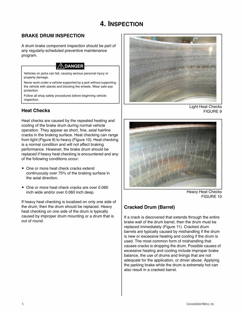
Heat checks are caused by the repeated heating and cooling of the brake drum during normal vehicle operation. They appear as short, fine, axial hairline cracks in the braking surface. Heat checking can range from light (Figure 9) to heavy (Figure 10). Heat checking is a normal condition and will not affect braking performance. However, the brake drum should be replaced if heavy heat checking is encountered and any of the following conditions occur:
� One or more heat check cracks extend continuously over 75% of the braking surface in the axial direction.
� One or more heat check cracks are over 0.060 inch wide and/or over 0.060 inch deep.
If heavy heat checking is localized on only one side of the drum, then the drum should be replaced. Heavy heat checking on one side of the drum is typically caused by improper drum mounting or a drum that is out of round. Figure 0.3
8
Light Heat ChecksFIGURE 9
Figure 0.4
9
Heavy Heat ChecksFIGURE 10
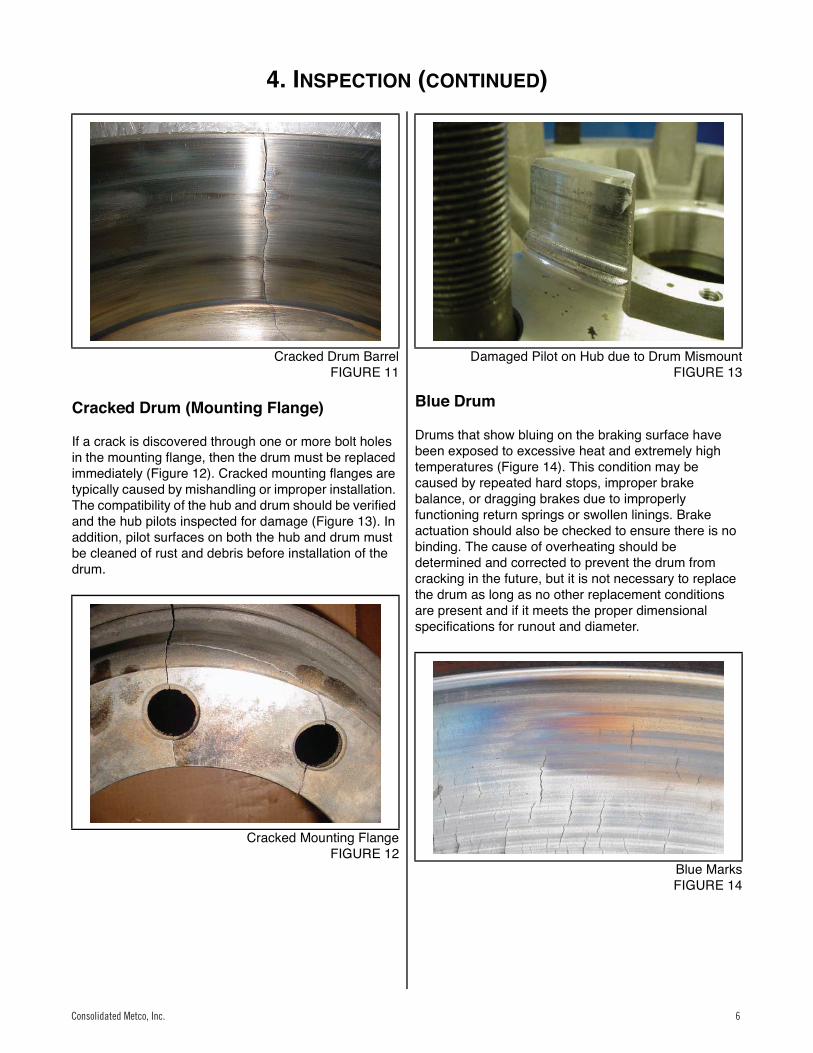
Cracked Drum (Barrel)
If a crack is discovered that extends through the entire brake wall of the drum barrel, then the drum must be replaced immediately (Figure 11). Cracked drum barrels are typically caused by mishandling if the drum is new or excessive heating and cooling if the drum is used. The most common form of mishandling that causes cracks is dropping the drum. Possible causes of excessive heating and cooling include improper brake balance, the use of drums and linings that are not adequate for the application, or driver abuse. Applying the parking brake while the drum is extremely hot can also result in a cracked barrel.Figure 0.5
Vehicles on jacks can fall, causing serious personal injury or property damage.Never work under a vehicle supported by a jack without supporting the vehicle with stands and blocking the wheels. Wear safe eye protection.Follow all shop safety procedures before beginning vehicle inspection.
Consolidated Metco, Inc.5
4. INSPECTION (CONTINUED)
6 Consolidated Metco, Inc.
10
Cracked Drum BarrelFIGURE 11
Cracked Drum (Mounting Flange)
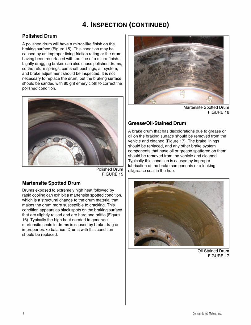
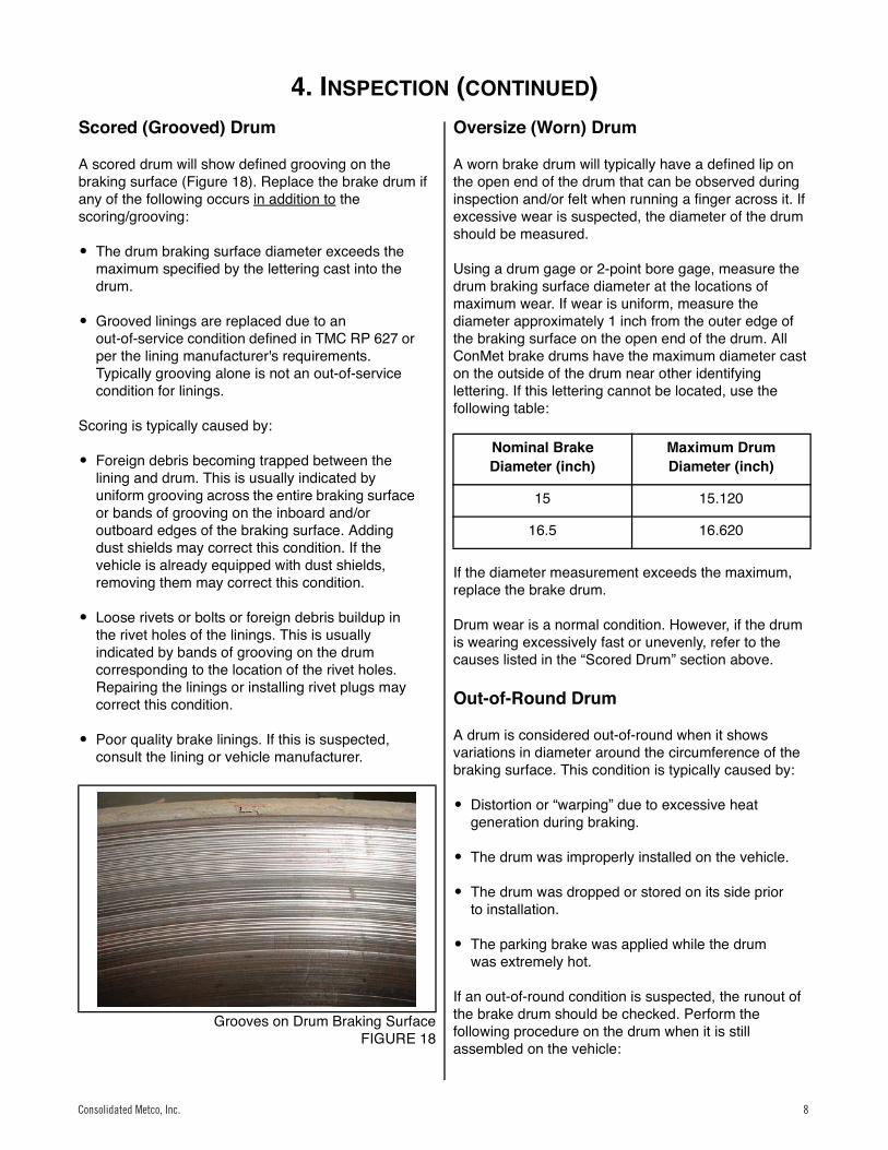
If a crack is discovered through one or more bolt holes in the mounting flange, then the drum must be replaced immediately (Figure 12). Cracked mounting flanges are typically caused by mishandling or improper installation. The compatibility of the hub and drum should be verified and the hub pilots inspected for damage (Figure 13). In addition, pilot surfaces on both the hub and drum must be cleaned of rust and debris before installation of the drum.Figure 0.6
11
Cracked Mounting FlangeFIGURE 12
Figure 0.7
12
Damaged Pilot on Hub due to Drum MismountFIGURE 13
Blue Drum
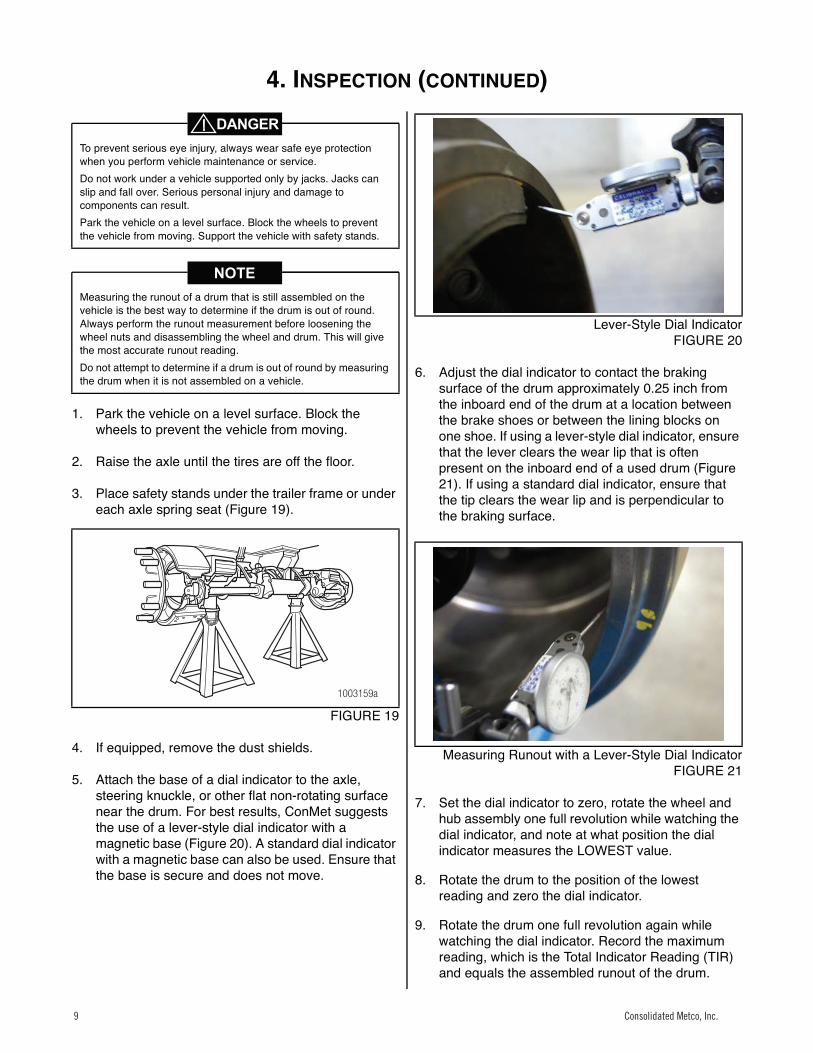
Drums that show bluing on the braking surface have been exposed to excessive heat and extremely high temperatures (Figure 14). This condition may be caused by repeated hard stops, improper brake balance, or dragging brakes due to improperly functioning return springs or swollen linings. Brake actuation should also be checked to ensure there is no binding. The cause of overheating should be determined and corrected to prevent the drum from cracking in the future, but it is not necessary to replace the drum as long as no other replacement conditions are present and if it meets the proper dimensional specifications for runout and diameter.Figure 0.8
13
Blue MarksFIGURE 14
Consolidated Metco, Inc. 6
4. INSPECTION (CONTINUED)
Consolidated Metco, Inc. 7
Polished DrumA polished drum will have a mirror-like finish on the braking surface (Figure 15). This condition may be caused by an improper lining friction rating or the drum having been resurfaced with too fine of a micro-finish. Lightly dragging brakes can also cause polished drums, so the return springs, camshaft bushings, air system, and brake adjustment should be inspected. It is not necessary to replace the drum, but the braking surface should be sanded with 80 grit emery cloth to correct the polished condition.Figure 0.9
14
Polished DrumFIGURE 15
Martensite Spotted DrumDrums exposed to extremely high heat followed by rapid cooling can exhibit a martensite spotted condition, which is a structural change to the drum material that makes the drum more susceptible to cracking. This condition appears as black spots on the braking surface that are slightly raised and are hard and brittle (Figure 16). Typically the high heat needed to generate martensite spots in drums is caused by brake drag or improper brake balance. Drums with this condition should be replaced.
15
Martensite Spotted DrumFIGURE 16
Grease/Oil-Stained DrumA brake drum that has discolorations due to grease or oil on the braking surface should be removed from the vehicle and cleaned (Figure 17). The brake linings should be replaced, and any other brake system components that have oil or grease spattered on them should be removed from the vehicle and cleaned. Typically this condition is caused by improper lubrication of the brake components or a leaking oil/grease seal in the hub.Figure 0.10
16
Oil-Stained DrumFIGURE 17
Consolidated Metco, Inc.7
4. INSPECTION (CONTINUED)
8 Consolidated Metco, Inc.
Scored (Grooved) Drum
A scored drum will show defined grooving on the braking surface (Figure 18). Replace the brake drum if any of the following occurs in addition to the scoring/grooving:
� The drum braking surface diameter exceeds the maximum specified by the lettering cast into the drum.
� Grooved linings are replaced due to an out-of-service condition defined in TMC RP 627 or per the lining manufacturer's requirements. Typically grooving alone is not an out-of-service condition for linings.
Scoring is typically caused by:
� Foreign debris becoming trapped between the lining and drum. This is usually indicated by uniform grooving across the entire braking surface or bands of grooving on the inboard and/or outboard edges of the braking surface. Adding dust shields may correct this condition. If the vehicle is already equipped with dust shields, removing them may correct this condition.
� Loose rivets or bolts or foreign debris buildup in the rivet holes of the linings. This is usually indicated by bands of grooving on the drum corresponding to the location of the rivet holes. Repairing the linings or installing rivet plugs may correct this condition.
� Poor quality brake linings. If this is suspected, consult the lining or vehicle manufacturer.
Figure 0.11
17
Grooves on Drum Braking SurfaceFIGURE 18
Oversize (Worn) Drum
A worn brake drum will typically have a defined lip on the open end of the drum that can be observed during inspection and/or felt when running a finger across it. If excessive wear is suspected, the diameter of the drum should be measured.
Using a drum gage or 2-point bore gage, measure the drum braking surface diameter at the locations of maximum wear. If wear is uniform, measure the diameter approximately 1 inch from the outer edge of the braking surface on the open end of the drum. All ConMet brake drums have the maximum diameter cast on the outside of the drum near other identifying lettering. If this lettering cannot be located, use the following table:
If the diameter measurement exceeds the maximum, replace the brake drum.
Drum wear is a normal condition. However, if the drum is wearing excessively fast or unevenly, refer to the causes listed in the “Scored Drum” section above.
Out-of-Round Drum
A drum is considered out-of-round when it shows variations in diameter around the circumference of the braking surface. This condition is typically caused by:
� Distortion or “warping” due to excessive heat generation during braking.
� The drum was improperly installed on the vehicle.
� The drum was dropped or stored on its side prior to installation.
� The parking brake was applied while the drum was extremely hot.
If an out-of-round condition is suspected, the runout of the brake drum should be checked. Perform the following procedure on the drum when it is still assembled on the vehicle:
Nominal Brake Diameter (inch)
Maximum Drum Diameter (inch)
15 15.120
16.5 16.620
Consolidated Metco, Inc. 8
4. INSPECTION (CONTINUED)
Consolidated Metco, Inc. 9
1. Park the vehicle on a level surface. Block the wheels to prevent the vehicle from moving.
2. Raise the axle until the tires are off the floor.
3. Place safety stands under the trailer frame or under each axle spring seat (Figure 19).
Figure 0.12
18
FIGURE 19
4. If equipped, remove the dust shields.
5. Attach the base of a dial indicator to the axle, steering knuckle, or other flat non-rotating surface near the drum. For best results, ConMet suggests the use of a lever-style dial indicator with a magnetic base (Figure 20). A standard dial indicator with a magnetic base can also be used. Ensure that the base is secure and does not move.
Figure 0.13
19
Lever-Style Dial IndicatorFIGURE 20
6. Adjust the dial indicator to contact the braking surface of the drum approximately 0.25 inch from the inboard end of the drum at a location between the brake shoes or between the lining blocks on one shoe. If using a lever-style dial indicator, ensure that the lever clears the wear lip that is often present on the inboard end of a used drum (Figure 21). If using a standard dial indicator, ensure that the tip clears the wear lip and is perpendicular to the braking surface.
Figure 0.14
20
Measuring Runout with a Lever-Style Dial IndicatorFIGURE 21
7. Set the dial indicator to zero, rotate the wheel and hub assembly one full revolution while watching the dial indicator, and note at what position the dial indicator measures the LOWEST value.
8. Rotate the drum to the position of the lowest reading and zero the dial indicator.
9. Rotate the drum one full revolution again while watching the dial indicator. Record the maximum reading, which is the Total Indicator Reading (TIR) and equals the assembled runout of the drum.
To prevent serious eye injury, always wear safe eye protection when you perform vehicle maintenance or service.Do not work under a vehicle supported only by jacks. Jacks can slip and fall over. Serious personal injury and damage to components can result.Park the vehicle on a level surface. Block the wheels to prevent the vehicle from moving. Support the vehicle with safety stands.
Measuring the runout of a drum that is still assembled on the vehicle is the best way to determine if the drum is out of round. Always perform the runout measurement before loosening the wheel nuts and disassembling the wheel and drum. This will give the most accurate runout reading.Do not attempt to determine if a drum is out of round by measuring the drum when it is not assembled on a vehicle.
1003159a
Consolidated Metco, Inc.9
4. INSPECTION (CONTINUED)
10 Consolidated Metco, Inc.
� If TIR is less than 0.020 inch, no action is necessary. Return the drum to service.
� If TIR exceeds 0.020 inch, mark the drum and hub so that the original position of the drum relative to the hub is known. Perform the following actions:
a. Remove the drum and inspect the hub/drum mating surfaces for damage. Pay special attention to the pilots on the hub. If damage is found, replace the damaged components.
b. If no damage is found, reinstall the brake drum 180 degrees from its original position relative to the hub. Make sure to rotate the hub so that one wheel pilot boss is at the 12 o'clock position prior to reinstalling the drum. Remeasure the runout. If the TIR is less than 0.020 inch, keep the drum in the new position and reassemble the wheel, again making sure that the hub is rotated so that one wheel pilot boss is at the 12 o'clock position. Return the drum to service. If the TIR exceeds 0.020 inch, replace the brake drum. For detailed drum and wheel installation procedures, refer to Section 7.
Drum ResurfacingConMet does not recommend resurfacing brake drums. However, if drum resurfacing is necessary, ensure that the finished diameter does not exceed 0.080 inch over the original diameter. For example, if the original drum diameter was 16.50 inches, then the maximum rebore diameter allowed is 16.50 + 0.080 = 16.580 inches. In addition, the braking surface finish must not exceed 200 microfinish, and the TIR must not exceed 0.020 inch when the drum is assembled on the vehicle.
Some vehicle manufacturers specify a lower hub/drum assembled runout limit on steer axles than 0.020 inch. In those cases, the vehicle manufacturerʼs limits must be met. Check with the vehicle manufacturer to confirm runout limits.
Consolidated Metco, Inc. 10
5. BRAKE DRUM REPLACEMENT
Consolidated Metco, Inc. 11
Brake Drum Replacement
Brake drums should be replaced if any of the following conditions are found:
� Heavy heat checking in addition to the criteria described in Section 4.
� Cracked drum barrel.
� Cracked mounting flange.
� Martensite spotting on the braking surface.
� Grooving in addition to the criteria described in Section 4.
� The drum is worn beyond the maximum diameter limit.
� The drum is out-of-round.
� The drum has been dropped.
� The drum is known to have been severely overheated or abused.
Drums should always be replaced in pairs on the same axle to ensure the same braking power and load is achieved. Uneven braking load on the axle can reduce the brake performance, service life, and/or safety of the vehicle. Linings should also always be replaced in pairs, though it is not always necessary to replace linings when replacing drums and vice versa. See Section 4 of this manual for more details.
SELECTION OF NEW BRAKE DRUMSSelecting the correct replacement brake drum for your application is very important as it ensures that your brake system's performance, service life, and safety are maintained. In order to determine a proper replacement, the following information about the drum that is being replaced will be needed:
� Manufacturer name
� Part number
Most manufacturers cast this information into the outside of the brake drum. Refer to Section 2 of this manual for specific information on identifying ConMet brake drums.
If the above information cannot be determined, then a truck dealership can be contacted and the Vehicle Identification Number (VIN) provided. The dealership should be able to determine the manufacturer and part number of the drum originally installed on the vehicle.
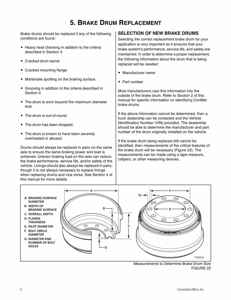
If the brake drum being replaced still cannot be identified, then measurements of the critical features of the brake drum will be necessary (Figure 22). The measurements can be made using a tape measure, calipers, or other measuring devices.
21
Measurements to Determine Brake Drum SizeFIGURE 22
106902a
A
B
C
GF
E
D
A. BRAKING SURFACE DIAMETER
B. WIDTH OF BRAKING SURFACE
C. OVERALL DEPTHD. FLANGE
THICKNESSE. PILOT DIAMETERF. BOLT CIRCLE
DIAMETERG. DIAMETER AND
NUMBER OF BOLT HOLES
Consolidated Metco, Inc.11
6. ADDITIONAL INFORMATION
12 Consolidated Metco, Inc.
Additional Information
BRAKE DRUM BALANCE
All ConMet brake drums are balanced at the factory using either a cut in the squealer band or a “Turned-to-Balance” machining process. No drums are balanced using weld-on weights. All steer drums are balanced to 10 inch-ounces and all rear/drive/trailer drums are balanced to 20 inch-ounces.
Balance Cut in Squealer Band
ConMet standard cast and CastLite® brake drums are 100% balanced at the factory by machining a balance cut in the squealer band (Figure 23). Each drum is first checked for imbalance, cut to correct any imbalance found, and then rechecked to ensure it meets specifications. The balance cut can easily be found by inspecting the squealer band.22
Balance Cut in Squealer BandFIGURE 23
Turned-to-Balance
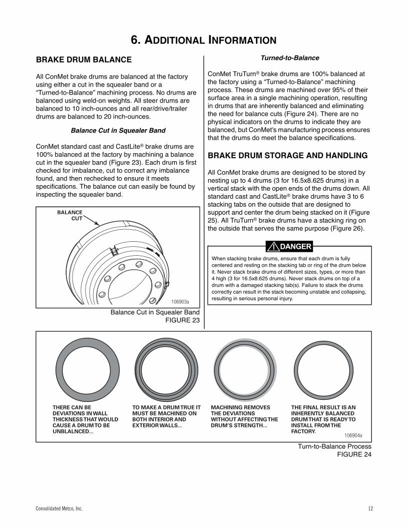
ConMet TruTurn® brake drums are 100% balanced at the factory using a “Turned-to-Balance” machining process. These drums are machined over 95% of their surface area in a single machining operation, resulting in drums that are inherently balanced and eliminating the need for balance cuts (Figure 24). There are no physical indicators on the drums to indicate they are balanced, but ConMet's manufacturing process ensures that the drums do meet the balance specifications.
BRAKE DRUM STORAGE AND HANDLING
All ConMet brake drums are designed to be stored by nesting up to 4 drums (3 for 16.5x8.625 drums) in a vertical stack with the open ends of the drums down. All standard cast and CastLite® brake drums have 3 to 6 stacking tabs on the outside that are designed to support and center the drum being stacked on it (Figure 25). All TruTurn® brake drums have a stacking ring on the outside that serves the same purpose (Figure 26).
Turn-to-Balance ProcessFIGURE 24
106903a
BALANCECUT
When stacking brake drums, ensure that each drum is fully centered and resting on the stacking tab or ring of the drum below it. Never stack brake drums of different sizes, types, or more than 4 high (3 for 16.5x8.625 drums). Never stack drums on top of a drum with a damaged stacking tab(s). Failure to stack the drums correctly can result in the stack becoming unstable and collapsing, resulting in serious personal injury.
106904a
THERE CAN BE DEVIATIONS IN WALL THICKNESS THAT WOULD CAUSE A DRUM TO BE UNBLALNCED...
TO MAKE A DRUM TRUE IT MUST BE MACHINED ON BOTH INTERIOR AND EXTERIOR WALLS...
MACHINING REMOVES THE DEVIATIONS WITHOUT AFFECTING THE DRUM’S STRENGTH...
THE FINAL RESULT IS AN INHERENTLY BALANCED DRUM THAT IS READY TO INSTALL FROM THE FACTORY.
Consolidated Metco, Inc. 12
6. ADDITIONAL INFORMATION – (CONTINUED)
13 Consolidated Metco, Inc.
24
Storing Standard Cast and CastLite® DrumsFIGURE 25
Figure 0.15
25
Storing TruTurn® DrumsFIGURE 26
WARNING
Brake drums are very heavy and manually handling them should be avoided. Specialty drum handling devices are available to aid in brake drum transport, installation, and removal. These devices are recommended to prevent personal injuries and component damage.
WARNING
WHEEL STUD HOLES
The stud holes in all of ConMet's drum flanges are clearance holes. They serve no purpose other than to let the wheel studs pass through the drum, and clearance hole size does not affect the stopping ability of the brake drum. This section explains the types of stud holes used by ConMet drums, and also addresses the common misconceptions about stud holes.
Cast Stud Holes
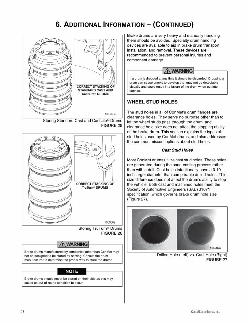
Most ConMet drums utilize cast stud holes. These holes are generated during the sand-casting process rather than with a drill. Cast holes intentionally have a 0.10 inch larger diameter than comparable drilled holes. This size difference does not affect the drumʼs ability to stop the vehicle. Both cast and machined holes meet the Society of Automotive Engineers (SAE) J1671 specification, which governs brake drum hole size (Figure 27). Figure 0.16
26
Drilled Hole (Left) vs. Cast Hole (Right)FIGURE 27
Brake drums manufactured by companies other than ConMet may not be designed to be stored by nesting. Consult the drum manufacturer to determine the proper way to store the drums.
Brake drums should never be stored on their side as this may cause an out-of-round condition to occur.
106905a
CORRECT STACKING OFSTANDARD CAST AND
CastLite® DRUMS
106906a
CORRECT STACKING OFTruTurn® DRUMS
If a drum is dropped at any time it should be discarded. Dropping a drum can cause cracks to develop that may not be detectable visually and could result in a failure of the drum when put into service.
Consolidated Metco, Inc.13
6. ADDITIONAL INFORMATION – (CONTINUED)
Consolidated Metco, Inc. 14
Large Diameter Stud Holes in Steer Drums
Many ConMet steer drums are designed to work with both hub piloted and stud piloted wheel mounting systems. Hub piloted systems utilize M22 wheel studs while stud piloted systems utilize 1-1/8 inch wheel studs. ConMet steer drums will often have stud hole diameters designed to clear the 1-1/8 inch wheel studs in stud piloted systems. These holes may look overly large when used with M22 studs in hub piloted systems. This is normal and does not affect the performance of the drum. See Section 2 of this manual for more information on hub and stud piloted systems.
Stud Hole Misconceptions
Several misconceptions exist about the function of the stud holes in brake drums:
� Misconception 1. The stud holes and studs prevent the drum from rotating with respect to the hub during braking.
Properly torqued fasteners provide twice the necessary clamp load to prevent the wheel, drum, and hub flanges from rotating with respect to one another. Clamp load generates friction between the flanges that prevents the drum from rotating relative to the hub and wheel, not shear loading of the wheel studs against the holes.
� Misconception 2. Drums pilot off of the stud hole and studs.
All drums have a precision machined pilot hole in the flange and all hubs have precision drum pilots. These pilots are what center the drum on the hub, not the studs and stud holes. This is true for both hub piloted and stud piloted systems.
� Misconception 3. Drum installation difficulty depends on stud hole size.
Brake drums are located on a truck axle with the help of the brake shoes and the hub's drum pilot. Stud hole size has no effect on ease of installation.
Consolidated Metco, Inc. 14
7. BRAKE DRUM AND WHEEL INSTALLATION
Consolidated Metco, Inc. 15
Brake Drum and Wheel Installation
Hub Pilot Wheel Mounting System
WARNING
27
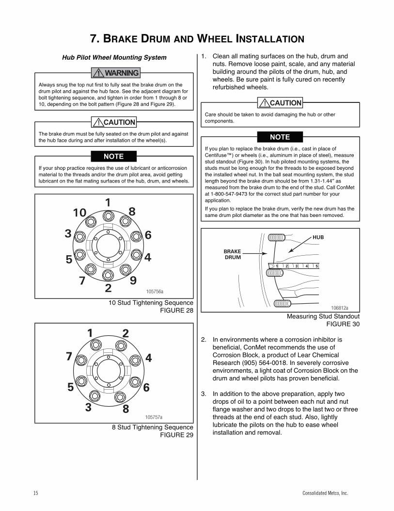
10 Stud Tightening SequenceFIGURE 28
28
8 Stud Tightening SequenceFIGURE 29
1. Clean all mating surfaces on the hub, drum and nuts. Remove loose paint, scale, and any material building around the pilots of the drum, hub, and wheels. Be sure paint is fully cured on recently refurbished wheels.
29
Measuring Stud StandoutFIGURE 30
2. In environments where a corrosion inhibitor is beneficial, ConMet recommends the use of Corrosion Block, a product of Lear Chemical Research (905) 564-0018. In severely corrosive environments, a light coat of Corrosion Block on the drum and wheel pilots has proven beneficial.
3. In addition to the above preparation, apply two drops of oil to a point between each nut and nut flange washer and two drops to the last two or three threads at the end of each stud. Also, lightly lubricate the pilots on the hub to ease wheel installation and removal.
Always snug the top nut first to fully seat the brake drum on the drum pilot and against the hub face. See the adjacent diagram for bolt tightening sequence, and tighten in order from 1 through 8 or 10, depending on the bolt pattern (Figure 28 and Figure 29).
The brake drum must be fully seated on the drum pilot and against the hub face during and after installation of the wheel(s).
If your shop practice requires the use of lubricant or anticorrosion material to the threads and/or the drum pilot area, avoid getting lubricant on the flat mating surfaces of the hub, drum, and wheels.
105756a
6
81
10
3
5 4
972
6
8
1
3
5
47
2
105757a
Care should be taken to avoid damaging the hub or other components.
If you plan to replace the brake drum (i.e., cast in place of Centifuse™) or wheels (i.e., aluminum in place of steel), measure stud standout (Figure 30). In hub piloted mounting systems, the studs must be long enough for the threads to be exposed beyond the installed wheel nut. In the ball seat mounting system, the stud length beyond the brake drum should be from 1.31-1.44″ as measured from the brake drum to the end of the stud. Call ConMet at 1-800-547-9473 for the correct stud part number for your application.If you plan to replace the brake drum, verify the new drum has the same drum pilot diameter as the one that has been removed.
1 2 3 4 5
106812a
HUB
BRAKEDRUM
Consolidated Metco, Inc.15
7. BRAKE DRUM AND WHEEL INSTALLATION (CONTINUED)
Consolidated Metco, Inc. 16
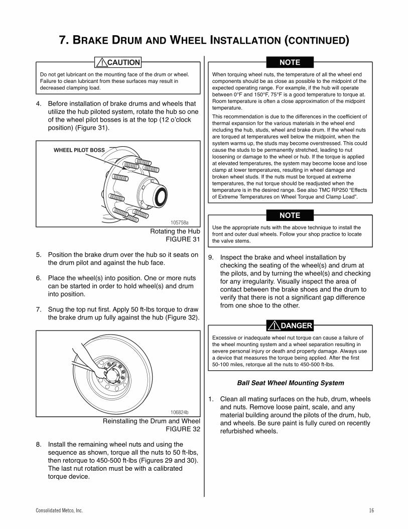
4. Before installation of brake drums and wheels that utilize the hub piloted system, rotate the hub so one of the wheel pilot bosses is at the top (12 oʼclock position) (Figure 31).
30
Rotating the HubFIGURE 31
5. Position the brake drum over the hub so it seats on the drum pilot and against the hub face.
6. Place the wheel(s) into position. One or more nuts can be started in order to hold wheel(s) and drum into position.
7. Snug the top nut first. Apply 50 ft-lbs torque to draw the brake drum up fully against the hub (Figure 32).
31
Reinstalling the Drum and WheelFIGURE 32
8. Install the remaining wheel nuts and using the sequence as shown, torque all the nuts to 50 ft-lbs, then retorque to 450-500 ft-lbs (Figures 29 and 30). The last nut rotation must be with a calibrated torque device.
9. Inspect the brake and wheel installation by checking the seating of the wheel(s) and drum at the pilots, and by turning the wheel(s) and checking for any irregularity. Visually inspect the area of contact between the brake shoes and the drum to verify that there is not a significant gap difference from one shoe to the other.
Ball Seat Wheel Mounting System
1. Clean all mating surfaces on the hub, drum, wheels and nuts. Remove loose paint, scale, and any material building around the pilots of the drum, hub, and wheels. Be sure paint is fully cured on recently refurbished wheels.
Do not get lubricant on the mounting face of the drum or wheel. Failure to clean lubricant from these surfaces may result in decreased clamping load.
105758a
WHEEL PILOT BOSS
106824b
When torquing wheel nuts, the temperature of all the wheel end components should be as close as possible to the midpoint of the expected operating range. For example, if the hub will operate between 0°F and 150°F, 75°F is a good temperature to torque at. Room temperature is often a close approximation of the midpoint temperature. This recommendation is due to the differences in the coefficient of thermal expansion for the various materials in the wheel end including the hub, studs, wheel and brake drum. If the wheel nuts are torqued at temperatures well below the midpoint, when the system warms up, the studs may become overstressed. This could cause the studs to be permanently stretched, leading to nut loosening or damage to the wheel or hub. If the torque is applied at elevated temperatures, the system may become loose and lose clamp at lower temperatures, resulting in wheel damage and broken wheel studs. If the nuts must be torqued at extreme temperatures, the nut torque should be readjusted when the temperature is in the desired range. See also TMC RP250 “Effects of Extreme Temperatures on Wheel Torque and Clamp Load”.
Use the appropriate nuts with the above technique to install the front and outer dual wheels. Follow your shop practice to locate the valve stems.
Excessive or inadequate wheel nut torque can cause a failure of the wheel mounting system and a wheel separation resulting in severe personal injury or death and property damage. Always use a device that measures the torque being applied. After the first 50-100 miles, retorque all the nuts to 450-500 ft-lbs.
Consolidated Metco, Inc. 16
7. BRAKE DRUM AND WHEEL INSTALLATION (CONTINUED)
17 Consolidated Metco, Inc.
32
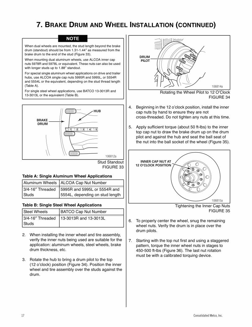
Stud StandoutFIGURE 33
Table A: Single Aluminum Wheel Applications
Table B: Single Steel Wheel Applications
2. When installing the inner wheel and tire assembly, verify the inner nuts being used are suitable for the application: aluminum wheels, steel wheels, brake drum thickness, etc.
3. Rotate the hub to bring a drum pilot to the top (12 oʼclock) position (Figure 34). Position the inner wheel and tire assembly over the studs against the drum.
33
Rotating the Wheel Pilot to 12 OʼClockFIGURE 34
4. Beginning in the 12 oʼclock position, install the inner cap nuts by hand to ensure they are not cross-threaded. Do not tighten any nuts at this time.
5. Apply sufficient torque (about 50 ft-lbs) to the inner top cap nut to draw the brake drum up on the drum pilot and against the hub and seat the ball seat of the nut into the ball socket of the wheel (Figure 35).
34
Tightening the Inner Cap NutsFIGURE 35
6. To properly center the wheel, snug the remaining wheel nuts. Verify the drum is in place over the drum pilots.
7. Starting with the top nut first and using a staggered pattern, torque the inner wheel nuts in stages to 450-500 ft-lbs (Figure 36). The last nut rotation must be with a calibrated torquing device.
When dual wheels are mounted, the stud length beyond the brake drum (standout) should be from 1.31-1.44″ as measured from the brake drum to the end of the stud (Figure 33).When mounting dual aluminum wheels, use ALCOA inner cap nuts 5978R and 5978L or equivalent. These nuts can also be used with longer studs up to 1.88″ standout.For special single aluminum wheel applications on drive and trailer hubs, use ALCOA single cap nuts 5995R and 5995L, or 5554R and 5554L or the equivalent, depending on the stud thread length (Table A).For single steel wheel applications, use BATCO 13-3013R and 13-3013L or the equivalent (Table B).
Aluminum Wheels ALCOA Cap Nut Number3/4-16″ Threaded Studs
5995R and 5995L or 5554R and 5554L, depending on stud length
Steel Wheels BATCO Cap Nut Number3/4-16″ Threaded Studs
13-3013R and 13-3013L
1 2 3 4 5
106812a
HUB
BRAKEDRUM
106814a
DRUMPILOT
106815a
INNER CAP NUT AT12 O’CLOCK POSITION
Consolidated Metco, Inc.17
7. BRAKE DRUM AND WHEEL INSTALLATION (CONTINUED)
Consolidated Metco, Inc. 18
35
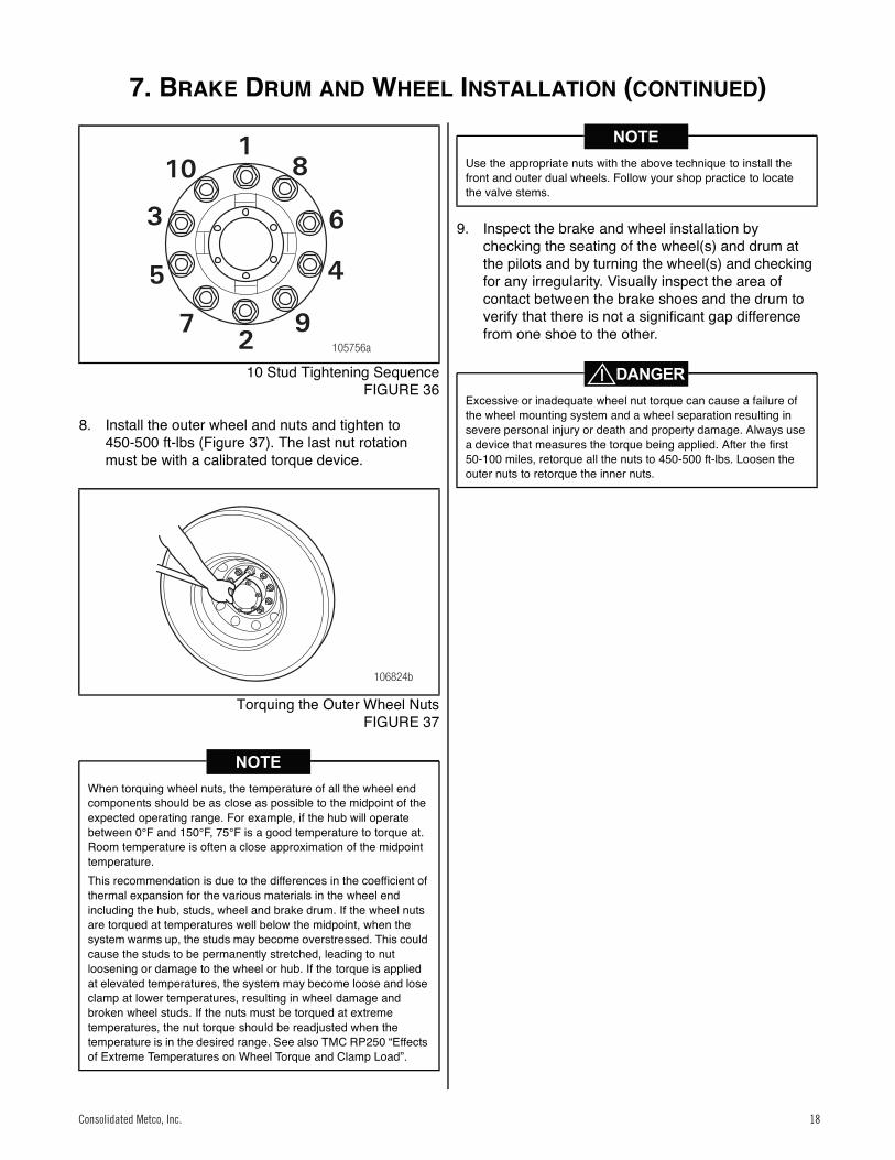
10 Stud Tightening SequenceFIGURE 36
8. Install the outer wheel and nuts and tighten to 450-500 ft-lbs (Figure 37). The last nut rotation must be with a calibrated torque device.
36
Torquing the Outer Wheel NutsFIGURE 37
9. Inspect the brake and wheel installation by checking the seating of the wheel(s) and drum at the pilots and by turning the wheel(s) and checking for any irregularity. Visually inspect the area of contact between the brake shoes and the drum to verify that there is not a significant gap difference from one shoe to the other.
When torquing wheel nuts, the temperature of all the wheel end components should be as close as possible to the midpoint of the expected operating range. For example, if the hub will operate between 0°F and 150°F, 75°F is a good temperature to torque at. Room temperature is often a close approximation of the midpoint temperature.This recommendation is due to the differences in the coefficient of thermal expansion for the various materials in the wheel end including the hub, studs, wheel and brake drum. If the wheel nuts are torqued at temperatures well below the midpoint, when the system warms up, the studs may become overstressed. This could cause the studs to be permanently stretched, leading to nut loosening or damage to the wheel or hub. If the torque is applied at elevated temperatures, the system may become loose and lose clamp at lower temperatures, resulting in wheel damage and broken wheel studs. If the nuts must be torqued at extreme temperatures, the nut torque should be readjusted when the temperature is in the desired range. See also TMC RP250 “Effects of Extreme Temperatures on Wheel Torque and Clamp Load”.
105756a
6
81
10
3
5 4
972
106824b
Use the appropriate nuts with the above technique to install the front and outer dual wheels. Follow your shop practice to locate the valve stems.
Excessive or inadequate wheel nut torque can cause a failure of the wheel mounting system and a wheel separation resulting in severe personal injury or death and property damage. Always use a device that measures the torque being applied. After the first 50-100 miles, retorque all the nuts to 450-500 ft-lbs. Loosen the outer nuts to retorque the inner nuts.
Consolidated Metco, Inc. 18
WHEEL TORQUE SPECIFICATIONS
19 Consolidated Metco, Inc.
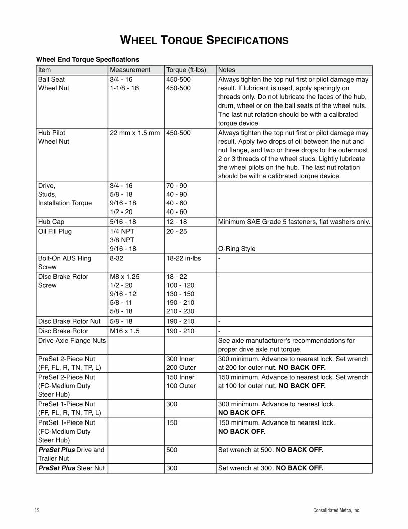
Wheel Torque Specifications
Wheel End Torque SpecficationsItem Measurement Torque (ft-lbs) NotesBall SeatWheel Nut
3/4 - 161-1/8 - 16
450-500450-500
Always tighten the top nut first or pilot damage may result. If lubricant is used, apply sparingly on threads only. Do not lubricate the faces of the hub, drum, wheel or on the ball seats of the wheel nuts. The last nut rotation should be with a calibrated torque device.
Hub PilotWheel Nut
22 mm x 1.5 mm 450-500 Always tighten the top nut first or pilot damage may result. Apply two drops of oil between the nut and nut flange, and two or three drops to the outermost 2 or 3 threads of the wheel studs. Lightly lubricate the wheel pilots on the hub. The last nut rotation should be with a calibrated torque device.
Drive,Studs,Installation Torque
3/4 - 165/8 - 189/16 - 181/2 - 20
70 - 9040 - 9040 - 6040 - 60
Hub Cap 5/16 - 18 12 - 18 Minimum SAE Grade 5 fasteners, flat washers only.Oil Fill Plug 1/4 NPT
3/8 NPT9/16 - 18
20 - 25
O-Ring StyleBolt-On ABS Ring Screw
8-32 18-22 in-lbs -
Disc Brake Rotor Screw
M8 x 1.251/2 - 209/16 - 125/8 - 115/8 - 18
18 - 22100 - 120130 - 150190 - 210210 - 230
-
Disc Brake Rotor Nut 5/8 - 18 190 - 210 -Disc Brake Rotor M16 x 1.5 190 - 210 -Drive Axle Flange Nuts See axle manufacturerʼs recommendations for
proper drive axle nut torque.PreSet 2-Piece Nut(FF, FL, R, TN, TP, L)
300 Inner200 Outer
300 minimum. Advance to nearest lock. Set wrench at 200 for outer nut. NO BACK OFF.
PreSet 2-Piece Nut(FC-Medium Duty Steer Hub)
150 Inner100 Outer
150 minimum. Advance to nearest lock. Set wrench at 100 for outer nut. NO BACK OFF.
PreSet 1-Piece Nut(FF, FL, R, TN, TP, L)
300 300 minimum. Advance to nearest lock.NO BACK OFF.
PreSet 1-Piece Nut(FC-Medium Duty Steer Hub)
150 150 minimum. Advance to nearest lock.NO BACK OFF.
PreSet Plus Drive and Trailer Nut
500 Set wrench at 500. NO BACK OFF.
PreSet Plus Steer Nut 300 Set wrench at 300. NO BACK OFF.
Consolidated Metco, Inc.19

Consolidated Metco, Inc. 20

TruTurn®
Brake Drums
Consolidated Metco, Inc. 5701 SE Columbia Way, Vancouver, WA 98661 • (800) 547-9473 • www.conmet.com
Part No. 100818037-2015 Printed in the USA
Notes: