heavy duty vertical machining center mynx
TRANSCRIPT

5400Ⅱ · 6500Ⅱ · 7500Ⅱ · 9500
MynxHEAVY DUTY VERTICAL MACHINING CENTER

02 /
Product Preview
Basic information
Basic Structure
Cutting
Performance
Detailed
Information
Options
Applications
Diagrams
Specifications
Customer Support
Service
Mynx ⅡseriesMynx Ⅱ series offers a wide line-up from 550 mm (21.7 inch) to 950 mm (37.4 inch) and various spindle enabling to meet the user to handle a wider range of workpieces. In addition, Mynx series offers high durability, high performance to designed high rigidity. The EOP functions for the user-friendliness has improved the convenience of customers.
Mynx 7500 II
MynxⅡ
series

03 02 /
Contents
02 Product Overview
Basic Information
04 Basic Structure
07 Cutting Performance
Detailed Information
08 Standard / Optional Specifications
10 Applications
13 Capacity Diagram
19 Machine / CNC Specifications
26 Customer Support Service
Users can be selected according to material and size of workpiece
Wide line-up from 550mm (21.7 inch) to
950mm (37.4 inch) and various spindle
are available to meet material and size of
workpiece.
High productivity and stable precision, powerful cutting performance
High-rigidity machine structure provides
high durability and stable accuracy during
heavy duty cutting.
Higher productivity can be achieved with the
CAM-type tool changer that supports faster
tool changing.
Easy operation for improving convinience to use NC system
Easy operation for user's convenient
machine operation.
The EOP functions for the user-friendliness
has improved the convenience of
customers.
Mynx 5400 II
Mynx 6500 II

04 /
Travel distance (X x Y x Z axis)
The Mynx II series offers a wide line-up. High-rigidity machinestructure provides highdurability and stableaccuracy during heavy duty cutting.
Applied a highly rigid box guideway structure suitable for heavy cutting. The extended box-type guideways improve the machine durability as well as rigidity and stability.
Basic Structure
Axis System
Models Rapid traverser rate (X / Y / Z)
Mynx 5400Ⅱ
30 / 30 / 24 m/min(1181.1 / 1181.1 / 944.9 ipm)
Mynx 5400/50Ⅱ
Mynx 6500Ⅱ
Mynx 6500/50Ⅱ
Mynx 7500Ⅱ
Mynx 7500/50Ⅱ
Mynx 950016 / 16 / 16 m/min
(629.9 /629.9 /629.9 ipm)
1020 x 550 x 530 mm
1525 x 770 x 625 mm
1270 x 670 x 625 mm
2500 x 950 x 850 mm
Mynx 5400Ⅱ, Mynx 5400/50Ⅱ
Mynx 7500Ⅱ, Mynx 7500/50Ⅱ
Mynx 6500Ⅱ, Mynx 6500/50Ⅱ
Mynx 9500 Z-axis
Y-axis
Mynx 5400Ⅱ, Mynx 6500Ⅱ
X-axis
(40.2 x 21.7 x 20.9 inch)
(50.0 x 26.4 x 24.6 inch)
(60.0 x 30.3 x 24.6 inch)
(98.4 x 37.4 x 33.5 inch)
Surface FinishThe surface of moving elements are coated with
Rulon 142 material to reduce friction and stick-slip.
This material is carefully hand-scraped to achieve
optimum accuracy.
MynxⅡ
series
Product Preview
Basic information
Basic Structure
Cutting
Performance
Detailed
Information
Options
Applications
Diagrams
Specifications
Customer Support
Service

05 04 /
Table Wide machining areaTravel distance (X x Y x Z axis)
Drive Systems
The MynxⅡseries spindles support Direct-driven, Belt-driven, Gear-driven, Built in-driven systems. Dual contact tool system support as standard.
Max weight on Table
A
B
Table size (A x B)
1200 x 540 mm
1400 x 670 mm
Mynx 5400Ⅱ, Mynx 5400/50Ⅱ
Mynx 6500Ⅱ, Mynx 6500/50Ⅱ
1600 x 750 mm
Mynx 7500Ⅱ, Mynx 7500/50Ⅱ
2500 x 950 mm
Mynx 9500
Models Taper Standard Optional
Mynx 5400Ⅱ***Mynx 6500Ⅱ***Mynx 7500Ⅱ***
ISO #408000r/min
(15/11 kW (20.1/14.8 Hp), 286.5 N·m (211.4 ft-lbs))
12000r/min(15.6 kW (20.9 Hp),
165.5 N·m (122.1 ft-lbs))
Mynx 5400/50ⅡMynx 6500/50Ⅱ ISO #50
6000r/min(15/11 kW (20.1/14.8 Hp), 286.4 N·m (211.4 ft-lbs))
6000r/min (18.5/15 kW (24.8/20.1 Hp),
307.2 N·m (226.7 ft-lbs))
6000r/min*(30/18.5 kW (40.2/24.8 Hp),
617.4 N·m (455.6 ft-lbs))
8000r/min(15/11 kW (20.1/14.8 Hp), 286.4 N·m (211.4 ft-lbs))
Mynx 7500/50Ⅱ ISO #506000r/min
(18.5/15 kW (24.8/20.1 Hp), 307.2 N·m (226.7 ft-lbs))
6000r/min(22/18.5 kW (29.5/24.8 Hp),
365.5 N·m (269.7 ft-lbs))
6000r/min*(30/18.5 kW (40.2/24.8 Hp),
617.4 N·m (455.6 ft-lbs))
8000r/min(15/11 kW (20.1/14.8 Hp), 286.4 N·m (211.4 ft-lbs))
Mynx 9500 ISO #506000r/min*
(30/18.5 kW (40.2/24.8 Hp), 617.4 N·m (455.6 ft-lbs))
10000r/min**(30/25 kW (40.2/33.5 Hp), 420
N·m (310.0 ft-lbs))
None : Belt-driven * :Gear-driven ** : Built in-driven *** : Direct-drivenMynx 9500 Gear-driven spindles
Mynx II series offers an optimized table for machine line up enabling to meet the user to handle a wider range of workpieces.
Users can select spindles of various driving systems and specifications according to the workpiece material.
Dual Contact SpindleThe system enables simultaneous dual-contact of tapered side using elastic
deformation of the spindle and perfect gauge control.
(47.2 x 21.3 inch)
(55.1 x 26.4 inch)
(63.0 x 29.5 inch)
(98.4 x 37.4 inch)
1000 kg
Mynx 5400Ⅱ, Mynx 5400/50Ⅱ
1300 kg
Mynx 6500Ⅱ, Mynx 6500/50Ⅱ
1500 kg
Mynx 7500Ⅱ, Mynx 7500/50Ⅱ
3500 kg
Mynx 9500
(2204.6 lb)
(2866.0 lb)
(3306.9 lb)
(7716.1 lb)
Taper contact
Flange contact
Spindle

06 /
Tool Changer
Higher productivity canbe achieved with theCAM-type tool changerthat supports faster toolchanging.
Tool Magazine
Automatic tool changer
Chain type CAM magazine
Drum-type CAM magazine
None : Drum-type CAM magazine * : Chain type CAM magazine (Servo type)
Models Taper Standard Optional
Mynx 5400Ⅱ
ISO #40 30 40Mynx 6500Ⅱ
Mynx 7500Ⅱ
Mynx 5400/50Ⅱ
ISO #50
24 -
Mynx 6500/50Ⅱ 24 30*
Mynx 7500/50Ⅱ 24 40*
Mynx 9500 30* 40*
Unit : ea
Weight
Length
Models TaperTool Change Time Max. Tool Size
T-T-T C-T-C Length Weight
Mynx 5400Ⅱ
ISO #40 1.3 s 3.7 s300mm
(11.8 inch)8kg
(17.6 lb)Mynx 6500Ⅱ
Mynx 7500Ⅱ
Mynx 5400/50Ⅱ
ISO #50 2.5 s 5.5 s350mm
(13.8 inch)20kg
(33.1 lb)
Mynx 6500/50Ⅱ
Mynx 7500/50Ⅱ
Mynx 9500MynxⅡ
series
Product Preview
Basic information
Basic Structure
Cutting
Performance
Detailed
Information
Options
Applications
Diagrams
Specifications
Customer Support
Service

07 06 /
The heavy-duty machining performance of the Mynx II series spindles is the best in its class.
Cutting Performance ISO #40
Result of cutting test on Mynx 5400Ⅱ (8000r/min, Direct, 15/11kW (20.1/14.8 Hp))
ISO #50
Result of cutting test on Mynx 9500 (6000r/min, Gear, 30/18.5kW (40.2/24.8 Hp))
Face mill (ø80 mm, Cut edge count :6) Carbon steel (SM45C)
Machining rate
(cm³/min (inch³/min))
Spindle speed
(r/min)Feedrate
(mm/min (ipm))
374.4 (22.8) 500 1950 (76.8)
Tap Carbon steel (SM45C)
Tap size
(mm (inch))
Spindle speed
(r/min)Feedrate
(mm/min (ipm))
M36 x P4.0 (M1.4 x P0.2) 265 1060 (41.7)
Drill (ø85 mm) Carbon steel (SM45C)
Machining rate
(cm³/min (inch³/min))
Spindle speed
(r/min)Feedrate
(mm/min (ipm))
510 (31.1) 562 90 (3.5)
Face mill (ø125 mm,Cut edge count :8) Carbon steel (SM45C)
Machining rate
(cm³/min (inch³/min))
Spindle speed
(r/min)Feedrate
(mm/min (ipm))
756 (46.1) 464 1080 (42.5)
Tap Carbon steel (SM45C)
Tap size
(mm (inch))
Spindle speed
(r/min)Feedrate
(mm/min (ipm))
M42 x P4.5 (M1.7 x P0.2) 100 450 (17.7)
Drill (ø50 mm) Carbon steel (SM45C)
Machining rate
(cm³/min (inch³/min))
Spindle speed
(r/min)Feedrate
(mm/min (ipm))
265.07 (16.2) 500 135 (5.3)
* The results, indicated in this catalogue are provides as example.
They may not be obtained due to differences in cutting conditions and environmental conditions during measurement.
* The results, indicated in this catalogue are provides as example.
They may not be obtained due to differences in cutting conditions and environmental conditions during measurement.
6.0 mm (0.2 inch)64 mm (2.5 inch)
7.0 mm (0.3 inch)100 mm (3.9 inch)

08 /
*Spindle cooling system (Oil cooler) is standard **Spindle cooling system (Oil cooler) is option ✽ Please contact Doosan to select detail specifications.(1) Please refer to foundation drawing in relation to anchoring. If more detail information want, consult with doosan service
(2) In case of using neat cutting oil, this device is highly recommended in order to reduce the change of accuracy by rising the coolant temperatures.(3) In case of TSC is not required and only TSA is needed, this option can be selected.
Standard / Optional Specifications Standard Optional X Not applicable
No. Description Features
Mynx 5400Ⅱ
Mynx 5400/50Ⅱ
Mynx 6500Ⅱ
Mynx 6500/50Ⅱ
Mynx 7500Ⅱ
Mynx 7500/50Ⅱ
Mynx 9500
Mynx 5400Ⅱ
SIEMENS
Mynx 5400/50ⅡSIEMENS
Mynx 6500Ⅱ
SIEMENS
Mynx 6500/50ⅡSIEMENS
Mynx 7500Ⅱ
SIEMENS
Mynx 7500/50ⅡSIEMENS
Mynx 9500
SIEMENS1
Spindle
6000 r/minBelt**
15/11 kW X ● X ● X X X
2 18.5/15 kW X ○ X ○ X ● X
3 22/18.5 kW X X X X X ○ X
4 Gear* 30/18.5 kW X ○ X ○ X ○ ●
58000 r/min
Direct 15/11 kW ● X ● X ● X X
6 Belt* 15/11 kW X ○ X ○ X ○ X
7 10000 r/min Built in* 15.6 kW X X X X X X ○
8 12000 r/min Direct* 15.6/15.6 kW ○ X ○ X ○ X X
9
Spindle cooling system(Oil cooler)
6000 r/minBelt* X ○ X ○ X ○ X
10 Gear* X ● X ● X ● ●
118000 r/min
Direct* ○ X ○ X ○ X X
12 Belt* X ● X ● X ● X
13 10000 r/min Built in* X X X X X X ●
14 12000 r/min Direct* ● X ● X ● X X
15Magazine Tool storage
capacity
24ea X ● X ● X ● X
16 30ea ● X ● ○ ● X ●
17 40ea ○ X ○ X ○ ○ ○
18
Tool shank type
ISO #40BIG PLUS BT40 ● X ● X ● X X
19 BIG PLUS CAT40 ○ X ○ X ○ X X
20 BIG PLUS DIN40 ○ X ○ X ○ X X
21ISO #50
BIG PLUS BT50 X ● X ● X ● ●
22 BIG PLUS CAT50 X ○ X ○ X ○ ○
23 BIG PLUS DIN50 X ○ X ○ X ○ ○
24
Coolant
FLOOD0.15 MPa (0.4 kW) ● ● ● ● ● ● ●
25 0.7 MPa (1.8 kW) ○ ○ ○ ○ ○ ○ ○
26
TSC
None ● ● ● ● ● ● ●
27 2 MPa (1.5kW) ○ ○ ○ ○ ○ ○ ○
28 2 MPa (4.0 kW) ○ ○ ○ ○ ○ ○ ○
29 7 MPa (5.5 kW) ○ ○ ○ ○ ○ ○ ○
30 SHOWER 0.1 MPa (1.1 kW) ○ ○ ○ ○ ○ ○ ○
31 Oil Skimmer Belt type ○ ○ ○ ○ ○ ○ ○
32 MQL ○ ○ ○ ○ ○ ○ ○
33
Chip disposal
Chip pan ● ● ● ● ● ● ●
34
Chip conveyorTYPE
HINGED PLATE ○ ○ ○ ○ ○ ○ ○
35 MAGNETIC SCRAPER ○ ○ ○ ○ ○ ○ ○
36 OUTLET DIRECTION RIGHT SIDE/LEFT SIDE ○ ○ ○ ○ ○ ○ ○
37Chip bucket
CAPACITY 220 / 300 / 380 ○ ○ ○ ○ ○ ○ ○
38 TYPE ROTATION / FORKLIFT ○ ○ ○ ○ ○ ○ ○
39Precision machining option
Smart Thermal Compensation X X X X X X ●
40 Linear scale X / Y / Zaxis ○ ○ ○ ○ ○ ○ ○
41 AICC I (40 block) ○ ○ ○ ○ ○ ○ ●
42 AICC II (200 block) ○ ○ ○ ○ ○ ○ ○
43
Measurement &Automation
Automatic tool measurement
TS27R ○ ○ ○ ○ ○ ○ ○
44 OTS ○ ○ ○ ○ ○ ○ ○
45 Automatic tool breakage detection ○ ○ ○ ○ ○ ○ ○
46 Automatic workpiece measurement OMP60 ○ ○ ○ ○ ○ ○ ○
47 Automatic front door with safety device ○ ○ ○ ○ ○ ○ ○
48
Accessories
WORK LIGHT LED LAMP ● ● ● ● ● ● ●
49 OPERATOR CALL LAMP 3-COLOR SIGNAL TOWER(LED) ● ● ● ● ● ● ●
50 SMART THERMAL CONTROL SENSORLESS TYPE (ONLY SPINDLE) ● ● ● ● ● ● ●
51 ASSEMBLY & OPERATION TOOLS KIT ● ● ● ● ● ● ●
52 AIR BLOWER ○ ○ ○ ○ ○ ○ ○
534TH AXIS PREPARATION CABLING FOR SERVO/1-PNEUMATIC PIPING
FACTORY READY MADE ○ ○ ○ ○ ○ ○ ○
54 AIR GUN ○ ○ ○ ○ ○ ○ ○
55 Coolant gun ○ ○ ○ ○ ○ ○ ○
56 Mist collector ○ ○ ○ ○ ○ ○ ○
57
Customized special option
ANCHORING(1) ○ ○ ○ ○ ○ ○ ○
58 COOLANT CHILLER(2) ○ ○ ○ ○ ○ ○ ○
59 TSA(3) 0.54 MPa ○ ○ ○ ○ ○ ○ ○
60 FEEDBACK SYSTEM HEIDENHAIN ○ ○ ○ ○ ○ ○ ○
61 RAISING BLOCK 150 / 200 / 300 mm ○ ○ ○ ○ ○ ○ ○
62 SIDE AUTO DOOR 680 X 1000 (W X H) SET ○ ○ ○ ○ ○ ○ ○
63 AWC 8PALLET ○ ○ ○ ○ ○ ○ ○
64 AUTO TOOL LENGTH MEASUREMEMT RENISHAW / LTS ○ ○ ○ ○ ○ ○ ○
65 AUTO TOOL BREAK-AGE DETECTION MSC/BK9(NEEDLE TYPE ON MAGAZINE) ○ ○ ○ ○ ○ ○ ○
MynxⅡ
series
Product Preview
Basic information
Basic Structure
Cutting
Performance
Detailed
Information
Options
Applications
Diagrams
Specifications
Customer Support
Service

09 08 /
Resolution : 0.001 mm
4th axis auxiliary device interface 59
Users who wish to set up a rotary axis on the table to increase application
flexibility are encouraged to contact Doosan in advance.
Hydraulic / Pneumatic fixture line
The user should prepare pipelines for hydraulic / pneumatic fixtures whose
detailed specifications should be determined by discussion with Doosan.
PneunmaticPneunmatic
Hydraulic
Hydraulic
Electronic
Servo driven Function and
Device
Oil Cooler
An oil cooler correlated to room temperature can
be equipped for a long-term operation at high
speed. Cooling oil circulates around the spindle
bearings to prevent thermal error of the spindle
and maintain machining accuracy.
Linear Scale 49
Using the linear scale feedback system, accuracy of the machine can be further
improved since the X, Y and Z axes can be controlled to correct positions.
Smart thermal compensation (Mynx 9500 only)
Smart thermal compensation function fitted as stadard optimizes machine accuracy of the spindle and structure by reducing the effects of heat build-up during extended periods of operation.
Drum filter typeMagnetic scraper typeHinged type
Chip conveyor 40~42
Chip conveyor type Material Description
Hinged type SteelHinged belt chip conveyor, which is most commonly used for steel work [for cleaning chips longer than 30mm(1.2inch)], is available as an option.
Magnetic scraper type
Cast IronMagnetic scraper type chip conveyor, which is ideal for die-casting work [for cleaning small chips], is available as an option.
Drum filter type
AluminiumDrum filter type chip conveyor, which is ideal for aluminium work [for filtering small chips], is available as an option.
AWC system The optimized solution to realize compact automation system
through automatic work-piece change system.
Max. workpiece dimensions Unit Count Max. loading Max. construction height on the pallet
250 x 250 (9.8x9.8) or ø 300 (11.8) mm (inch) 12 130kg (286.6lb)
350mm(13.8inch)
320 x 320 (12.6x12.6) or ø 360 (14.2) mm (inch) 10
250kg(551.1lb)
350 x 350 (13.8x13.8) or ø 400 (15.7) mm (inch) 8400 x 400 (15.7x15.7) or ø 450 (17.7) mm (inch) 6500 x 500 (19.7x19.7) or ø 550 (21.7) mm (inch) 4
W X H = 1,900 X 1,700 (74.8 X 66.9)
W
H
250 X 250(9.8 X 9.8)
320 X 320(12.6 X 12.6)
350 X 350(13.8 X 13.8)
400 X 400(15.7 X 15.7)
500 X 500(19.7 X 19.7)
Pallet Storage–Table Configuration Unit : mm (inch)
Peripheral Equipment

10 /
DOOSAN Fanuc i Plus
DOOSAN Fanuc i Plus is optimized for maximizing customer productivity and convenience.
DOOSAN Fanuc i Plus• 15 inch color display
Intuitive and user-friendly design
USB & PCMCIA card QWERTY keyboard• EZ-guide i standard
• Ergonimic operator panel
• 2MB Memory
• Hot key
15 inch screen + New OP
DOOSAN Fanuc i Plus' operation panel enhances operating convenience by incorporating
common-design buttons and layout, and features the Qwerty keyboard for fast and easy
operation.
iHMI Touch screen
iHMI provides an intuitive interface that utilizes a touch screen for quick and easy operation
and provides a variety of applications that can help machine operation.
• PLANNINGTool information such as tool offset and tool life can be checked and set, and scheduler function is provided.
• MACHININGMDI, EDIT, MEM, JOG screen can be changed by using touch function, and it is quick and easy to move to sub menu by using soft key.
• IMPROVEMENTUser can set up to record data for analysis and monitor the specific signals by setting up the maintenance and inspection function. Also user can add items.
• UTILITYView and search PDF and TEXT files, create notes from text / images / drawings, and link to web pages. For users who are familiar with the DDOOSAN Fanuc i Plus screen, the screen can be switched.
Product Preview
Basic information
Basic Structure
Cutting
Performance
Detailed
Information
Options
Applications
Diagrams
Specifications
Customer Support
Service
MynxⅡ
series

11 10 /
SIEMENS 828D 15.6 inch screen + New OP
The newly-designed operation panel enhances operating convenience by incorporating common-design buttons and layout, and features the Qwerty keyboard for fast and easy operation.
Conversational Convenient function
The machining monitoring function developed on the basis of the Shop Mill – an interactive machining support function of SIEMENS – provides users with cutting, servicing and maintenance screens for easy and convenient machine operation.
SIEMENS CNC optimizedfor DOOSAN machinetools maximizes usersʼproductivity.
• USB (standard)
• QWERTY Keyboard (standard)
15.6-inch display
Simulation and machining contour monitoringSimulation results with different viewscan be checked.
Shop Mill Part ProgrammingIt helps to write the part program and shorten the writing time.
Smart functionColor highlighting is provided for each processing code function, and the calculator can be used easily by using the pocket calculator on display.
Advanced program language programGUIDEIncreases program flexibility, minimizing cycle time.
Side screen widgetThrough the side widget, operator can easily monitor the current machining status.

12 /
Tool Management
Pattern Cycle & Engraving
Alarm Guidance
ATC Recovery
Function to manage tool information[Tool information]- Tool No. / Tool name- Tool condition : normal, large diameter, worn/ damaged, used for the first time, anual
Function to create frequently-used cutting programs automatically- Pattern Cycle: creates a program for a pre-defined shape- Engraving: creates a program for cutting a shape described with characters
Function to show detailed info on frequently triggered alarms and recommended actions
Function to view detailed info with recommended actions and to perform step-by-step operation manually (when an alarm is triggered during an ATC operation)
Adaptive Feed Control (AFC)
Tool Load Monitor
Work Offset Setting
Sensor Status Monitor
Function to control feedrate so that the cutting can be carried out at a constant load (To adapt to the spindle load set up with constant load feedrate control function)
Function to automatically monitor tool load(Different loads can be set for one tool according to M700 ~ M704)
Function to configure various work offset settings
Function to view sensor conditions of the machine
The software developed by Doosan's own technologyprovides numerousfunctions designed forconvenient operation.
Easy OperationPackage
MynxⅡ
series
Product Preview
Basic information
Basic Structure
Cutting
Performance
Detailed
Information
Options
Applications
Diagrams
Specifications
Customer Support
Service
13 12 /
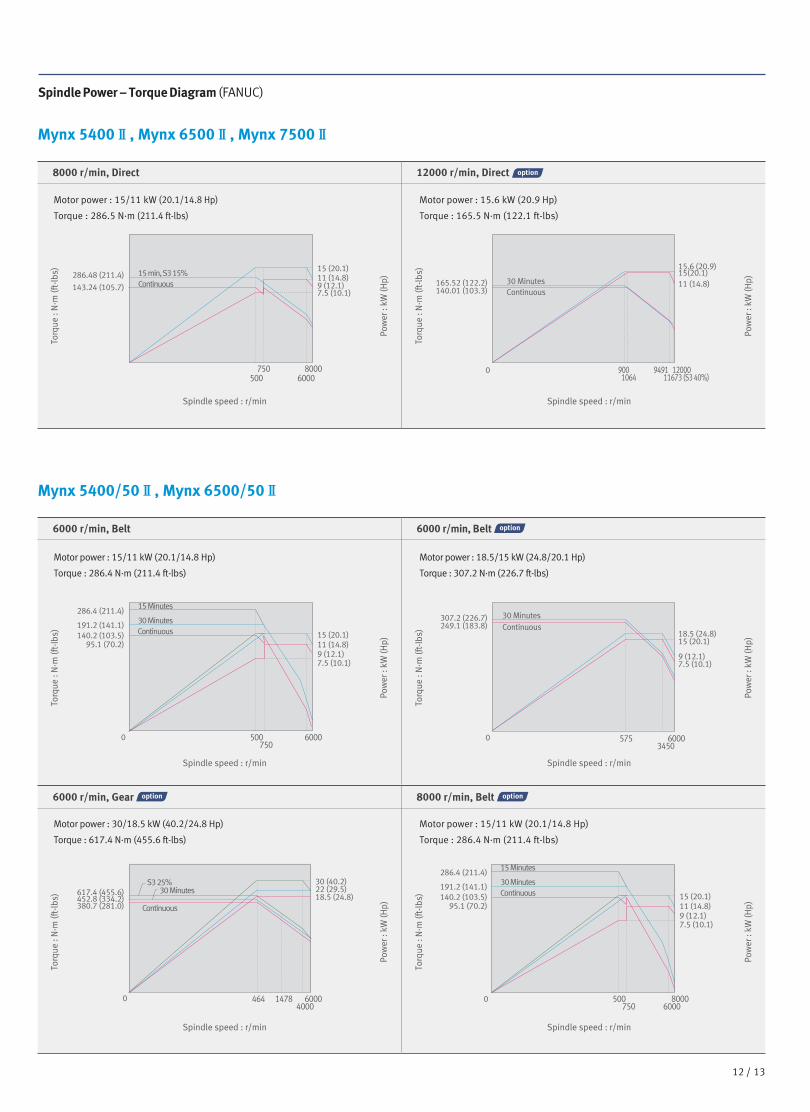
Spindle Power – Torque Diagram (FANUC)
Mynx 5400Ⅱ, Mynx 6500Ⅱ, Mynx 7500Ⅱ
Mynx 5400/50Ⅱ, Mynx 6500/50Ⅱ
8000 r/min, Direct 12000 r/min, Direct
6000 r/min, Belt 6000 r/min, Belt
6000 r/min, Gear 8000 r/min, Belt
Spindle speed : r/min
Pow
er :
kW (H
p)
Torq
ue :
N·m
(ft-
lbs)
Spindle speed : r/min
Pow
er :
kW (H
p)
Torq
ue :
N·m
(ft-
lbs)
Spindle speed : r/min
Pow
er :
kW (H
p)
Torq
ue :
N·m
(ft-
lbs)
Spindle speed : r/min
Pow
er :
kW (H
p)
Torq
ue :
N·m
(ft-
lbs)
Spindle speed : r/min
Pow
er :
kW (H
p)
Torq
ue :
N·m
(ft-
lbs)
Spindle speed : r/min
Pow
er :
kW (H
p)
Torq
ue :
N·m
(ft-
lbs)
Motor power : 15/11 kW (20.1/14.8 Hp)
Torque : 286.5 N·m (211.4 ft-lbs)
Motor power : 15.6 kW (20.9 Hp)
Torque : 165.5 N·m (122.1 ft-lbs)
Motor power : 15/11 kW (20.1/14.8 Hp)
Torque : 286.4 N·m (211.4 ft-lbs)
Motor power : 30/18.5 kW (40.2/24.8 Hp)
Torque : 617.4 N·m (455.6 ft-lbs)
Motor power : 18.5/15 kW (24.8/20.1 Hp)
Torque : 307.2 N·m (226.7 ft-lbs)
Motor power : 15/11 kW (20.1/14.8 Hp)
Torque : 286.4 N·m (211.4 ft-lbs)
500750
6000
286.4 (211.4)
15 (20.1)
15 (20.1)11 (14.8)9 (12.1)7.5 (10.1)
11 (14.8)
7.5 (10.1)9 (12.1)
191.2 (141.1)
286.48 (211.4)
143.24 (105.7)
140.2 (103.5)95.1 (70.2)
0
15 Minutes
15 min, S3 15%Continuous
30 MinutesContinuous 18.5 (24.8)
15 (20.1)
9 (12.1)7.5 (10.1)
307.2 (226.7)249.1 (183.8)
165.52 (122.2)140.01 (103.3)
0
30 MinutesContinuous
30 MinutesContinuous
5753450
6000
80006000
750500 11673 (S3 40%)1064
1200094919000
30 (40.2)22 (29.5)18.5 (24.8)617.4 (455.6)
452.8 (334.2)380.7 (281.0)
0 500750 6000
8000464 14784000
6000
286.4 (211.4)
15 (20.1)11 (14.8)
7.5 (10.1)9 (12.1)
191.2 (141.1)140.2 (103.5)
95.1 (70.2)
0
15 Minutes
30 MinutesContinuous30 Minutes
S3 25%
Continuous
15.6 (20.9)15(20.1)11 (14.8)

14 /
Spindle Power – Torque Diagram (FANUC)
Mynx 7500/50Ⅱ
6000 r/min, Belt 6000 r/min, Belt
Spindle speed : r/min
Pow
er :
kW (H
p)
Torq
ue :
N·m
(ft-
lbs)
Spindle speed : r/min
Pow
er :
kW (H
p)
Torq
ue :
N·m
(ft-
lbs)
Motor power : 18.5/15 kW (24.8/20.1 Hp)
Torque : 307.2 N·m (226.7 ft-lbs)
Motor power : 22/18.5 kW (29.5/24.8 Hp)
Torque : 365.5 N·m (269.7 ft-lbs)
6000 r/min, Gear 8000 r/min, Belt
Motor power : 30/18.5 kW (40.2/24.8 Hp)
Torque : 617.4 N·m (455.6 ft-lbs)
Motor power : 15/11 kW (20.1/14.8 Hp)
Torque : 286.4 N·m (211.4 ft-lbs)
Mynx 9500
6000 r/min, Gear 10000 r/min, Built in
Motor power : 30/18.5 kW (40.2/24.8 Hp)
Torque : 617.4 N·m (455.6 ft-lbs)
Motor power : 30/25 kW (40.2/33.5 Hp)
Torque : 420 N·m (310.0 ft-lbs)
18.5 (24.8)15 (20.1)
9 (12.1)7.5 (10.1)
307.2 (226.7)249.1 (183.8)
0
30 MinutesContinuous
5753450
6000
22 (29.5)18.5 (24.8)
11 (14.8)9 (12.1)
365.5 (269.7)307.7 (227.1)
0
30 Minutes
Continuous
5753450
6000
500750 6000
8000
286.4 (211.4)
15 (20.1)11 (14.8)
7.5 (10.1)9 (12.1)
191.2 (141.1)140.2 (103.5)
95.1 (70.2)
0
15 Minutes
30 MinutesContinuous
30 MinutesS3 25%
Continuous
500600
20002500
10000
420 (310.0)349.9 (258.2)238.1 (175.7)
30 (40.2)25 (33.5)22 (29.5)15 (20.1)
0 10
30 (40.2)22 (29.5)18.5 (24.8)617.4 (455.6)
452.8 (334.2)380.7 (281.0)
0 464 14784000
6000
30 MinutesS3 25%
Continuous
30 (40.2)22 (29.5)18.5 (24.8)
0 464 14784000
6000
30 MinutesS3 25%
Continuous
617.4 (455.6)452.8 (334.2)380.7 (281.0)
Spindle speed : r/min
Pow
er :
kW (H
p)
Torq
ue :
N·m
(ft-
lbs)
Spindle speed : r/min
Pow
er :
kW (H
p)
Torq
ue :
N·m
(ft-
lbs)
Spindle speed : r/min
Pow
er :
kW (H
p)
Torq
ue :
N·m
(ft-
lbs)
Spindle speed : r/min
Pow
er :
kW (H
p)
Torq
ue :
N·m
(ft-
lbs)
MynxⅡ
series
Product Preview
Basic information
Basic Structure
Cutting
Performance
Detailed
Information
Options
Applications
Diagrams
Specifications
Customer Support
Service

15 14 /
Spindle Power – Torque Diagram (SIEMENS)
Motor power : 22/18.5 kW (29.5/24.8 Hp)
Torque : 365.5 N·m (269.7 ft-lbs)
Motor power : 15/11 kW (20.1/14.8 Hp)
Torque : 286.4 N·m (211.4 ft-lbs)
Motor power : 30/25 kW (40.2/33.5 Hp)
Torque : 420 N·m (310.0 ft-lbs)
12000 r/min, Direct
6000 r/min, Gear
8000 r/min, Belt
0 500 1500 55006500
12000
0 464 14786000
5693
Continuous
S6 60%S6 40%
18.5 (24.8)
9.6 (12.9)
22.2(29.8)
11.2 (15.0)
27.8 (37.3)
12.4 (16.6)
7.6 (5.6) 8.9 (6.6) 9.9 (7.3)
157 (115.9) 188 (138.7) 234 (172.7)
27.8 (37.3) 22.2 (29.8) 18.5 (24.8)
760.0 (560.9)608.5 (449.1)507.1 (374.2)
188.4 (139.0)157.0 (115.9)
27.8 (37.3) 22.2 (29.8) 18.5 (24.8)
Continuous
S6 60%S6 40%
0 500 15006500
5500 8000
Continuous
S6 60%S6 40%
234 (172.7)
Motor power : 27.8 /18.5 kW (37.3/24.8
Hp)
Torque : 234.0 N·m (172.7 ft-lbs)
Motor power : 27.8 /18.5 kW (37.3/24.8
Hp)
Torque : 760.0 N·m (560.9 ft-lbs)
Motor power : 27.8 /18.5 kW (37.3/24.8
Hp)
Torque : 234.0 N·m (172.7 ft-lbs)
Spindle speed : r/min
Pow
er :
kW (H
p)
Torq
ue :
N·m
(ft-
lbs)
Spindle speed : r/min
Pow
er :
kW (H
p)
Torq
ue :
N·m
(ft-
lbs)
Spindle speed : r/min
Pow
er :
kW (H
p)
Torq
ue :
N·m
(ft-
lbs)

16 /
Spindle Power – Torque Diagram (HEIDENHAIN)
8000 r/min, Belt 6000 r/min, Gear
6000 r/min, Gear 10000 r/min, Built-in
Spindle speed : r/min Spindle speed : r/min
Pow
er :
kW (H
p)
Pow
er :
kW (H
p)
464 5000
1000 10000
550060000
S6 60%Continous
Continous
761.5 (562.0)617.4 (455.6)
238.73 (176.2)
514.5 (379.7)411.6 (303.8)
37 (49.6)30 (40.2) 25 (33.5)
25 (33.5)
20 (26.8)
S6 40%
S6 60%Continous
S6 40%
S6 25%
800055000 1500
70007400
241.9 (178.5)
38 (51.0) 30 (40.2) 24 (32.2)
191 (141.0)152.8 (112.8)
40.93 (S6 60%)
30.97 (Continuous)
222.8 (164.4) 191.0(141.0) 140.1(103.4)
292.8 (216.1)
28.4 (21.0)
9.0(6.6)
44.1 (32.5)
11.7(8.6)
51.4 (37.9)
14.7(10.8)
87.9 (64.9)
15.4 (11.4)
22 (29.5)
11.3 (15.2)
30 (40.2)
14.8 (19.8)
35 (46.9) 46 (61.7)
18.5 (24.8) 19.4 (26.0)
1500 50006500 12000
7400
157 (115.9)
7.6 (5.6)
188 (138.7)
8.9 (6.6)
234 (172.7)
9.9 (7.3)
142 (104.8) 121(89.3)
181(133.6) 18.5 (24.8
9.6 (12.9)
22.2(29.8)
11.2 (15.0)
27.8 (37.3)
12.4 (16.6)
27.2 (20.1)32.6 (24.1)48.3 (35.6)
500 15006500
120005500
S6 60%S1 Continous
S6 40%S6 25%
Torq
ue :
N·m
(ft-
lbs)
Torq
ue :
N·m
(ft-
lbs)
Mynx 5400 /50Ⅱ, Mynx 6500/50Ⅱ, Mynx 7500/50Ⅱ
Mynx 9500
Motor power : 38/24 kW (51.0/32.2 Hp)
Torque : 241.9 N·m (178.5 ft-lbs)
Motor power : 37/20 kW (49.6/26.8 Hp)
Torque : 761.5 N·m (562.0 ft-lbs)
Motor power : 37/20 kW (49.6/26.8 Hp)
Torque :761.5 N·m (562.0 ft-lbs)
Motor power : 25 kW (33.5 Hp)
Torque : 238.7 N·m (176.2 ft-lbs)
MynxⅡ
series
Product Preview
Basic information
Basic Structure
Cutting
Performance
Detailed
Information
Options
Applications
Diagrams
Specifications
Customer Support
Service

17 16 /
Motor power : 37/20 kW (49.6/26.8 Hp)
Torque :761.5 N·m (562.0 ft-lbs)
Motor power : 25 kW (33.5 Hp)
Torque : 238.7 N·m (176.2 ft-lbs)
External Dimensions
MynxⅡseries
Front View
Top View
Unit : mm (inch)
D
AE
C B (Right)B(Left)
D
AE
C B (Right)B(Left)
✽ Contact Doosan for more information to rear chip conveyor.
* Some peripheral equipment can be placed in other places
A(Max. machine length)
B*(Additional width to
accommodate the side chip conveyor)
C(Max. machine width)
D(Max. machine height)
E(Height from the floor to
the chip outlet)
Mynx 5400Ⅱ 3450 (135.8) Left & Right : 930 (36.6) 3350 (131.9) 3020 (118.9) 830 (32.7)
Mynx 5400/50Ⅱ 3450 (135.8) Left & Right : 930 (36.6) 3350 (131.9) 2920 (115.0) 830 (32.7)
Mynx 6500Ⅱ 3670 (144.5) Left & Right : 930 (36.6) 3350 (131.9) 3110 (122.4) 830 (32.7)
Mynx 6500/50Ⅱ 3670 (144.5) Left & Right : 930 (36.6) 3350 (131.9) 3020 (118.9) 830 (32.7)
Mynx 7500Ⅱ 4410 (173.6) Left & Right : 1060 (41.7) 3900 (153.5) 3230 (127.2) 980 (38.6)
Mynx 7500/50Ⅱ 4680 (184.3) Left & Right : 1060 (41.7) 4050 (159.4) 3300 (129.9) 980 (38.6)
Mynx 9500 5350 (210.6) Left & Right : 1170 (46.1) 6560 (258.3) 3600 (141.7) 770 (30.3)

18 /
Table
Mynx 5400Ⅱ, Mynx 5400/50Ⅱ
Mynx 9500
Mynx 7500Ⅱ, Mynx 7500/50Ⅱ
Mynx 6500Ⅱ, Mynx 6500/50Ⅱ
Unit : mm (inch)
Unit : mm (inch)
Unit : mm (inch)
Unit : mm (inch)
60 (2
.4)
540
(21.
3)
82.5
(3.2
)
1200 (47.2)
32 (1
.3)
12 (0
.5)
T-slot section
18H8
32 (1
.3)
12 (0
.5)
T-slot section
18H8
32 (1
.3)
12 (0
.5)
T-slot section
18H8
22H8
600 (23.6) 600 (23.6)
82.5
(3.2)
125
(4.9)
125
(4.9)
125
(4.9)
1400 (55.1)
60 (2.4
) 67
0 (2
6.4)
5 (0
.2)
750
(29.
5)10
0(3
.9)
10 (0.4
)
700 (27.6) 700 (27.6)
85 (3.3
)85 (3.3
)12
5(4
.9)
125
(4.9
)12
5(4
.9)
125
(4.9
)12
5(4
.9)
125
(4.9
)12
5(4
.9)
125
(4.9
)62
.5(2
.5)
62.5
(2.5
)
125
(4.9
)
2720 (107.1) 2500 (98.4)
1250 (49.2) 1250 (49.2)
1800 (70.9)1600 (63.0)
800 (31.5) 800 (31.5)100 (3.9) 100 (3.9)
110 (4.3)
1175
(46.
3)
950 (
37.4
)
160
(6.3
)16
0(6
.3)
160
(6.3
)16
0(6
.3)
155
(6.1
)
215
(8.5
)
155
(6.1
)10
(0
.4)
110 (4.3)
17 (0
.7)
38 (1.5)
40 (1
.6)
T-slot section
30 (1.2)
30 (1.2)
30 (1.2)
MynxⅡ
series
Product Preview
Basic information
Basic Structure
Cutting
Performance
Detailed
Information
Options
Applications
Diagrams
Specifications
Customer Support
Service

19 18 /
{ } : Option
Machine Specifications
MynxⅡseries
Description Unit Mynx 5400Ⅱ Mynx 5400/50ⅡTravels
Travel distance
X axis mm (inch) 1020 (40.2)Y axis mm (inch) 550 (21.7)Z axis mm (inch) 530 (20.9)
Distance from spindle nose to table top mm (inch) 150 ~ 680 (5.9 ~ 26.8) 200 ~ 730 (7.9 ~ 28.7)Table Table size mm (inch) 1200 x 540 (47.2 x 21.3)
Table loading capacity kg (lb) 1000 (2204.6)Table surface type mm (inch) T-SLOT [4-125(4.9) x 18(0.7)H8]
Spindle
Max. spindle speed
FANUC
Direct r/min 8000 {12000} -Belt r/min - 6000 {6000} {8000}Gear r/min - {6000}Built in r/min - -
SIEMENS
Direct r/min 12000 - Belt r/min - 8000Gear r/min - {6000}Built in r/min - -
HEIDENHAIN
Direct r/min 12000 -Belt r/min - 8000Gear r/min - {6000}Built in r/min - -
Taper - ISO #40 ISO #50
Spindle power
FANUC
Direct kW (Hp)15/11(20.1/14.8)
15.6/15.6 (20.9/20.9)-
Belt kW (Hp) -15/11 (20.1/14.8)
{18.5/15 (24.8/20.1)}{15/11 (20.1/14.8)}
Gear kW (Hp) - {30/18.5 (40.2/24.8)}Built in kW (Hp) - -
SIEMENS
Direct kW (Hp) 21.8/16.3 (29.2/21.9) -Belt kW (Hp) - 20/18.5 (29.5/24.8)Gear kW (Hp) - {27.8/18.5 (37.3/24.8)}Built in kW (Hp) - -
HEIDENHAIN
Direct kW (Hp) 46/22 (61.7/29.5) -Belt kW (Hp) - 38/24 (51.0/32.2)Gear kW (Hp) - {37/20 (49.6/26.8)}Built in kW (Hp) - -
Max. spindle torque
FANUC
Direct N·m (ft-lbs)286.5 (211.4)
{165.5 (122.1)}-
Belt N·m (ft-lbs) -286.4 (211.2)
{307.2 (226.7)} {286.4 (211.2)}Gear N·m (ft-lbs) - {617.4 (455.6)}Built in N·m (ft-lbs) - -
SIEMENS
Direct N·m (ft-lbs) 150.1 (110.8) -Belt N·m (ft-lbs) - 298.3 (220.1)Gear N·m (ft-lbs) - {760 (560.9)}Built in N·m (ft-lbs) - -
HEIDENHAIN
Direct N·m (ft-lbs) 292.8 (216.1) -Belt N·m (ft-lbs) - 241.9 (178.5)Gear N·m (ft-lbs) - {761.5 (562.0)}Built in N·m (ft-lbs) - -
Feedrates Rapid traverse rate
X axis m/min (ipm) 30 (1181.1)Y axis m/min (ipm) 30 (1181.1)Z axis m/min (ipm) 24 (944.9)
Automatic Tool Changer
Type of tool shank
Tool shank - BT 40 {CAT40/DIN40} BT 50 {CAT50 /DIN50}Pull stud - PS806 P50T-1 45deg
Tool storage capa. ea 30 {40} 24
Max. tool diameter
Continous mm (inch)80 (3.1)
{76 (3.0)}125 (4.9)
Without Adjacent Tools mm (inch) 125 (4.9) 220 (8.7)Max. tool length mm (inch) 300 (11.8) 350 (13.8)Max. tool weight kg (lb) 8 (17.6) 15 (33.1)Max. tool moment N·m (ft-lbs) 5.88 (4.3) 12.74 (9.4)Tool seletion MEMORY RANDOM
Tool change time (Tool-to-tool) sec 1.3 2.5
Tool change time (Chip-to-chip) sec 3.7 5.5 Power source Electric
power supply(rated capacity)
Direct FANUC kVA 32.3 {44.5} -
BeltFANUC kVA - 36.1 {40} {36.1}HEIDENHAIN kVA 47 {56} 47 {56}SIEMENS kVA - 48.7
GearFANUC kVA - {47.7}HEIDENHAIN kVA
Built in FANUC kVA - -Compressed air supply Mpa (psi) 0.54 (78.3)
Tank capacity Coolant tank capacity L (gal) 380 (100.4)
Machine Dimensions
Height mm (inch) 2800 (110.2) 3015 (118.7)Length mm (inch) 2467 (97.1) 2467 (97.1)Width mm (inch) 3350 (131.9) 3350 (131.9)Weight kg (lb) 7000 (15432) 7200 (15873)
Control NC system - DOOSAN Fanuc i Plus, Fanuc 32i {SIEMENS S828D / HEIDENHAIN TNC 620}

20 /
Description Unit Mynx 6500Ⅱ Mynx 6500/50Ⅱ Mynx 7500Ⅱ Mynx 7500/50Ⅱ Mynx 9500Travels
Travel distance
X axis mm (inch) 1270 (50.0) 1525 (60.0) 2500 (98.4)Y axis mm (inch) 670 (26.4) 770 (30.3) 950 (37.4)Z axis mm (inch) 625 (24.6) 625 (24.6) 850 (33.5)
Distance from spindle nose to table top mm (inch) 150 ~ 775 (5.9 ~ 30.5) 200 ~ 825 (7.9 ~ 32.5) 150 ~ 775 (5.9 ~ 30.5) 200 ~ 825 (7.9 ~ 32.5)200 ~ 1000 (7.9 ~
39.4)Table
Table size mm (inch) 1400 x 670 (55.1 x 26.4) 1600 x 750 (63.0 x 29.5)2500 x 950
(98.4 x 37.4)Table loading capacity kg (lb) 1300 (2866.0) 1500 (3306.9) 3500 (7716.2)
Table surface type mm (inch) T-SLOT [5-125(4.9) x 18(0.7)H8] T-SLOT [6-125(4.9) x 18(0.7)H8]T-SLOT [5-160(6.3) x
22(0.9)H8]Spindle
Max. spindle speed
FANUC
Direct r/min 8000 {12000} - 8000 {12000} - -Belt r/min - 6000 {6000} {8000} - 6000 {6000} {8000} -Gear r/min - {6000} - {6000} 6000Built in r/min - - - - {10000}
SIEMENS
Direct r/min 12000 - 12000 - - Belt r/min - 8000 - 8000Gear r/min - {6000} - {6000} {10000}Built in r/min - - - - 6000
HEIDENHAIN
Direct r/min 12000 - 12000 - -Belt r/min - 8000 - 8000 -Gear r/min - {6000} - {6000} 6000Built in r/min - - - - {10000}
Taper - ISO #40 ISO #50 ISO #40 ISO #50 ISO #50
Spindle power
FANUC
Direct kW (Hp) 15/11(20.1/14.8)15.6/15.6 (20.9/20.9)
-15/11(20.1/14.8)
15.6/15.6 (20.9/20.9)- -
Belt kW (Hp) -15/11 (20.1/14.8)
{18.5/15 (24.8/20.1)}{15/11 (20.1/14.8)}
-18.5/15 (24.8/20.1)
{22/18.5 (29.5/24.8)}{15/11 (20.1/14.8)}
-
Gear kW (Hp) - {30/18.5 (40.2/24.8)} - {30/18.5 (40.2/24.8)} 30/18.5 (40.2/24.8)Built in kW (Hp) - - - - {30/25 (40.2/33.5)}
SIEMENS
Direct kW (Hp) 21.8/16.3 (29.2/21.9) - 21.8/16.3 (29.2/21.9) - -Belt kW (Hp) - 20/18.5 (26.8/24.8) - 20/18.5 (26.8/24.8) -Gear kW (Hp) - {27.8/18.5 (37.3/24.8)} - {27.8/18.5 (37.3/24.8)}Built in kW (Hp) - - - - {25 (33.5)}
HEIDENHAIN
Direct kW (Hp) 46/22 (61.7/29.5) - 46/22 (61.7/29.5) - -Belt kW (Hp) - 38/24 (51.0/32.2) - 38/24 (51.0/32.2) 27.8/18.5 (37.3/24.8)Gear kW (Hp) - {37/20 (49.6/26.8)} - {37/20 (49.6/26.8)}Built in kW (Hp) - - - - {25 (33.5)}
Max. spindle torque
FANUC
Direct N·m (ft-lbs)286.5 (211.4)
{165.5 (122.1)}-
286.5 (211.4){165.5 (122.1)}
- -
Belt N·m (ft-lbs) -286.4 (211.2)
{307.2 (226.7)}{286.4 (211.2)}
-307.2 (226.7)
{365.5 (269.5)}{286.4 (211.2)}
-
Gear N·m (ft-lbs) - {617.4 (455.6)} - {617.4 (455.6)} 617.4 (455.6)Built in N·m (ft-lbs) - - - - {420 (310.0)}
SIEMENS
Direct N·m (ft-lbs) 150.1 (110.8) - 150.1 (110.8) - -Belt N·m (ft-lbs) - 298.3 (220) - 298.3 (220.1) -Gear N·m (ft-lbs) - {760 (560.5)} - {760 (560.5)}Built in N·m (ft-lbs) - - - - {238.8 (176.2)}
HEIDENHAIN
Direct N·m (ft-lbs) 292.8 (216.1) - 292.8 (216.1) - -Belt N·m (ft-lbs) - 241.9 (178.5) - 241.9 (178.5) 760 (560.5)Gear N·m (ft-lbs) - {761.5 (562.0)} - {761.5 (562.0)} -Built in N·m (ft-lbs) - - - - {238.8 (176.2)}
Feedrates Rapid traverse rate
X axis m/min (ipm) 30 (1181.1) 16 (629.9)Y axis m/min (ipm) 30 (1181.1) 16 (629.9)Z axis m/min (ipm) 24 (944.9) 16 (629.9)
Automatic Tool Changer
Type of tool shank
Tool shank - BT 40 {CAT40 /DIN40} BT 50 {CAT50 /DIN50} BT 40 {CAT40 /DIN40} BT 50 {CAT50 /DIN50} BT 50 {CAT50 /DIN50}Pull stud - PS806 P50T-1 45deg PS806 P50T-1 45deg P50T-1 45deg
Tool storage capa. ea 30 {40} 24 {30} 30 {40} 24 {40} 30 {40}
Max. tool diameter
Continous mm (inch)80 (3.1)
{76 (3.0)}125 (4.9)
80 (3.1) {76 (3.0)}
125 (4.9) 125 (4.9)
Without Adjacent Tools mm (inch) 125 (4.9) 220 (8.7) 125 (4.9) 220 (8.7) 220 (8.7)Max. tool length mm (inch) 300 (11.8) 350 (13.8) 300 (11.8) 350 (13.8) 350 (13.8)Max. tool weight kg (lb) 8 (17.6) 15 (33.1) 8 (17.6) 15 (33.1) 15 (33.1)Max. tool moment N·m (ft-lbs) 5.88 (4.3) 22 (16.2) 5.88 (4.3) 22 (16.2) 22 (16.2)Tool seletion MEMORY RANDOMTool change time (Tool-to-tool) sec 1.3 2.5 1.3 2.5 2.5 Tool change time (Chip-to-chip) sec 3.7 5.5 3.7 5.5 6.67
Power source Electric
power supply(rated capacity)
Direct FANUC kVA 35.1 {47.3} - 38.5 {50.7} - -
BeltFANUC kVA - 39.4 {44.6} {48.4} - 47.3 {51.8} {42.9} -HEIDENHAIN kVA 47 {56} 47 {56} 47 {56} 40 {56} -SIEMENS kVA - - - 60 -
GearFANUC kVA - {48.4} - {51.8} 47.0 HEIDENHAIN kVA
Built in FANUC kVA - - - - {54.2}Compressed air supply Mpa (psi) 0.54 (78.3)
Tank capacity Coolant tank capacity L (gal) 420 (97.8) 470 (124.2) 500 (132.1)
Machine Dimensions
Height mm (inch)F_3107 (122.3)
H/S_3216 (126.6)3016 (118.7)
F_3227 (127.0)H/S_3337 (131.4)
3292 (129.6) 3598 (141.7)
Length mm (inch) 2692 (106.0) 2629 (103.5) 3900 (153.5) 3900 (153.5) 4315 (169.9)Width mm (inch) 3350 (131.9) 3350 (131.9) 4050 (159.4) 4050 (159.4) 6480 (255.1)Weight kg (lb) 9000 (19842) 9500 (20944) 13500 (29762) 13500 (29762) 23000 (50706)
Control NC system - DOOSAN Fanuc i Plus, Fanuc 32i {SIEMENS S828D / HEIDENHAIN TNC 620}
{ } : Option
MynxⅡ
series
Machine SpecificationsProduct Preview
Basic information
Basic Structure
Cutting
Performance
Detailed
Information
Options
Applications
Diagrams
Specifications
Customer Support
Service
21 20 /
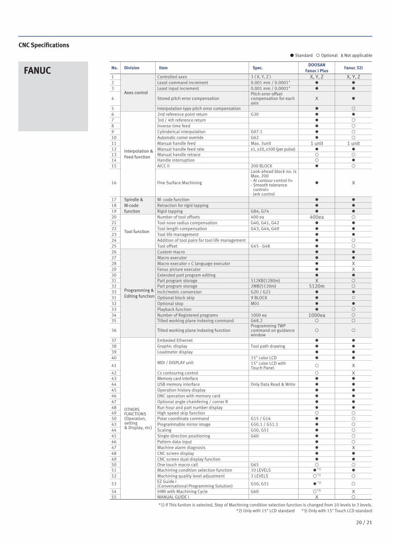
CNC Specifications
FANUC
*1) If This funtion is selected, Step of Machining condition selection function is changed from 10 levels to 3 levels.*2) Only with 15" LCD standard *3) Only with 15" Touch LCD standard
No. Division Item Spec.DOOSAN
Fanuc i PlusFanuc 32i
1
Axes control
Controlled axes 3 ( X, Y, Z ) X, Y, Z X, Y, Z2 Least command increment 0.001 mm / 0.0001" ● ●3 Least input increment 0.001 mm / 0.0001" ● ●
4 Stored pitch error compensationPitch error offset compensation for each axis
X ●
5 Interpolation type pitch error compensation ●
6
Interpolation & Feed function
2nd reference point return G30 ● ●7 3rd / 4th reference return ●
8 Inverse time feed ●
9 Cylinderical interpolation G07.1 ●
10 Automatic corner override G62 ●
11 Manual handle feed Max. 3unit 1 unit 1 unit12 Manual handle feed rate x1, x10, x100 (per pulse) ● ●13 Manual handle retrace 14 Handle interruption ●15 AICC II 200 BLOCK ●
16 Fine Surface Machining
Look-ahead block no. is Max. 200- AI contour control II+- Smooth tolerance
control+- Jerk control
● X
17 Spindle & M-code function
M- code function ● ●18 Retraction for rigid tapping ● ●19 Rigid tapping G84, G74 ● ●20
Tool function
Number of tool offsets 400 ea 400ea
21 Tool nose radius compensation G40, G41, G42 ● ●22 Tool length compensation G43, G44, G49 ● ●23 Tool life management ● ●24 Addition of tool pairs for tool life management ●
25 Tool offset G45 - G48 ●
26
Programming & Editing function
Custom macro ● ●27 Macro executor ● ●28 Macro executor + C language executor ● X
29 Fanuc picture executor ● X
30 Extended part program editing ● ●31 Part program storage 512KB(1280m) X 32 Part program storage 2MB(5120m) 5120m
33 Inch/metric conversion G20 / G21 ● ●31 Optional block skip 9 BLOCK ● ○32 Optional stop M01 ● ●33 Playback function ●
34 Number of Registered programs 1000 ea 1000ea 35 Tilted working plane indexing command G68.2
36 Tilted working plane indexing functionProgramming TWP command on guidance window
37
OTHERSFUNCTIONS(Operation,setting& Display, etc)
Embeded Ethernet ● ●38 Graphic display Tool path drawing ● ●39 Loadmeter display ● ●40
MDI / DISPLAY unit 15" color LCD ● ●
41 15" color LCD with Touch Panel X
42 Cs contouring control X43 Memory card interface ● ●44 USB memory interface Only Data Read & Write ● ●45 Operation history display ● ●46 DNC operation with memory card ● ●47 Optional angle chamfering / corner R ● ●48 Run hour and part number display ● ●49 High speed skip function 50 Polar coordinate command G15 / G16 ●
43 Programmable mirror image G50.1 / G51.1 ●
44 Scaling G50, G51 ●
45 Single direction positioning G60 ●
46 Pattern data input ●
47 Machine alarm diagnosis ● X
48 CNC screen display ● ●49 CNC screen dual display function ● ●50 One touch macro call G65 51 Machining condition selection function 10 LEVELS ●*1) ●52 Machining quality level adjustment 3 LEVELS *1)
53 EZ Guide i (Conversational Programming Solution) G50, G51 ●*2)
54 iHMI with Machining Cycle G60 *3) X55 MANUAL GUIDE i X
Standard Optional X Not applicable

22 /
CNC Specifications
SIEMENS No. Division Item Spec.Mynx9500 Mynx5400/
6500/7500S840Dsl S828D
1
Axescontrol
Controlled axes3 axes X, Y, Z X, Y, Z
2 4 axes ○ ○
3 5 axes ○ ○
4 Additional controlled axes Max. 31 axes in total(S840Dsl)/Max. 5 axes in total(S828D)
○ ○
5
Simultaneously controlled axes
Positioning(G00)/Linear interpolation(G01) : 3 axes Circular interpolation(G02, G03) : 2 axes
● ●
6Positioning(G00)/Linear interpolation(G01) : 4 axes Circular interpolation(G02, G03) : 2 axes
X X
7Positioning(G00)/Linear interpolation(G01) : 5 axes Circular interpolation(G02, G03) : 2 axes
X X
8 Backlash compensation ● ●
9 Leadscrew error compensation ● ●
10 Measuring system error compensa-tion
● ●
11 Feedforward control velocity-dependent ● ●
12 Follow up mode ● ●
13 Programmable acceleration ● ●
14 Emergency stop / overtravel ● ●
15
Interpo-lation & Feed functions
2nd reference point return G75 FP=2 ● ●
16 3rd / 4th reference return G75 FP=3, 4 ● ●
17 Linear interpolation Max. 4 ● ●
18 Circular interpolation G02, G03 ● ●
19 Inverse time feedrate G93 ● ●
20 Helical interpolation ● ●
21 Universal interpolator NURBS ● ●
22 Spline interpolation (A, B and C splines)
● ○
23
Spindle Functions
Spindle override 50 - 120 % ● ●
24 Automatic gear state selection ● ●
25 Oriented spindle stop ● ●
26 Tapping with compensating chuck/rigid tapping
● ●
27
Tool FunctionsTool radius compensations in plane
With approach and retract strategies
● ●
28 With transition circle/ellipse on outer edges
● ●
29 3D Tool radius compensation ○ ○
30
Programming & Editing functions
Program functions
31 • Dynamic preprocessing memory FIFO
● ●
32 Program editor
33 • Programming graphics/free contour input (contour calculator)
● ●
34 • Screens for 1/2/3-point contours (contour definition programming)
● ●
35 • Support for parameter input Animated Elements
● ●
36 • Shopturn/ShopMill Machining step programming
● ●
37 Technology cycles for drilling/milling
● ●
38
Others functions (Operation, setting & Display, etc)
JOG39 • Handwheel selection ● ●
40 • Switchover: inch/metric ● ●
41 • Manual measurement of zero/work offset ● ●
42 • Manual measurement of tool offset ● ●
43 • Automatic tool/workpiece measurement ● ●
44 • Reference point approach, automatic/via CNC program ● ●
45 Preset46 • Set actual value ● ●
47 15.0" color display ○ X
4815.6" color display with touch screen
● ●
49 18.5" color display with touch screen ○ X
50 Alarms and messages ● ●
51 Automatic measuring cycles ● ○
52 Easy Extend X ●
53 Contour handwheel ○ ○
Standard Optional X Not applicable
MynxⅡ
series
Product Preview
Basic information
Basic Structure
Cutting
Performance
Detailed
Information
Options
Applications
Diagrams
Specifications
Customer Support
Service

23 22 /
HEIDENHAIN
Standard Optional X Not applicable
No. 항목 상세 TNC 640
1
Axescontrol
Controlled axes 3 axes X, Y, Z
2 4 axes ○
3 5 axes X4 Additional controlled axes 6 axes X5 Simultaneously controlled axes Controlled axes ●
6 Controlled axes Max. 18 axes in totalOPT (Max.
6axes)7 Least command increment 0.0001 mm (0.0001 inch), 0.0001° ●
8 Least input increment 0.0001 mm (0.0001 inch), 0.0001° ●
9 Maximum commandable value ±99999.999mm (±3937 inch) ●
10 Axis feedback controlDouble-speed control loops for high-frequency spindles and torque/linear motors
○
11MDI / DISPLAY unit
15.1 inch TFT color flat panel ●
12 19 inch TFT color flat panel X13 Program memory for NC programs SSDR 8GB14 Block processing time 1.5 ms15 Cycle time for path interpolation CC 61xx 3 ms16 Encoders Absolute encoders EnDat 2.217
Interpolation
Straight line 5 AXES18 Circle 3 axes19 Helix, Combination of circular and linear motion ●
20 Spline interpolation ●
21Configuration Machine parameters
Numerical structure X
22 Tree structure with symbolic names of the parameters ●
23 Tabular representation ●
24
Commissioning and diagnostics
Integrated oscilloscope ●
25 OnLine monitor (OLM) ●
26 BUS diagnostics ●
27 DriveDiag ●
28 ApiData function ●
29 Trace function ●
30 Table function ●
31 Logic diagram ●
32 I/O-Force List ●
33 Log ●
34Machine operating panel
TE 735 ●
35 TE 745 X
36 Electronic handwheels HR 510 ●
37Data interfaces
Ethernet interface ●
38 USB interface (USB 2.0) ●
39
Machine functions
Feedrate override 0 - 150 % (10% unit) ●
40 Spindle orientation ●
41 Spindle speed command S5 digits ●
42 Spindle speed override 0 - 150 % ●
43
Monitoring functions
Position monitoring ●
44 Movement monitoring ●
45 Standstill monitoring ●
46 Positioning window ●
47 Temperature monitoring ●
48 Amplitude of encoder signals ●
49 Edge separation of encoder signals ●
50 Nominal speed value ●
51 Buffer battery ●
52 Run-time of PLC program ●
53 Emergency-stop monitoring ●
54 Internal power supply and housing fan ●
55 Gantry axes and master-slave torque control ○
56 Look-ahead (Intelligent path control by calculating the path speed ahead of time)
Max. 1024 blocks. X
57 Max. 5000 blocks. ●
58 ADP (Advanced Dynamic Prediction) X
59 HSC filters ●
60 Switching the traverse ranges ●
61 C-axis operation Spindle motor drives the rotary axis ●
62
User functions
Program inputAccording to ISO X
63 With smarT.NC X
64 With smartSelect ●
65Position entry
Nominal positions for lines and arcs in Cartesian coordinates
●
66 Incremental or absolute dimensions ●
67 Display and entry in mm or inches ●

24 /
CNC Specifications
HEIDENHAINNo. Division Item Spec.
TNC 620
Mynx 5400Ⅱ, Mynx 5400/50ⅡMynx 6500Ⅱ, Mynx 6500/50ⅡMynx 7500Ⅱ, Mynx 7500/50Ⅱ
Mynx 9500
1
Axes
Controlled axes 3 axes X, Y, Z X, Y, Z
2 4 axes ○ ○
3 Controlled axes Max. 12 axes in total ○ ○
4Least command incremen
0.0001 mm (0.0001 inch), 0.0001°
● ●
5 Least input increment 0.0001 mm (0.0001 inch), 0.0001°
● ●
6Maximum commandable value
±99999.999mm (±3937 inch) ● ●
7 Axis feedback controlDouble-speed control loops for high-frequency spindles and torque/linear motors
○ ○
8MDI / DISPLAY unit
15.1 inch TFT color flat panel ● ●
9 19 inch TFT color flat panel ○ ○
10Program memory for NC programs
SSDR 21GB 21GB
11 Block processing time 0.5 ms 0.5 ms
12Cycle time for path interpolation
CC 61xx 3 ms 3 ms
13 Encoders Absolute encoders EnDat 2.2EnDat
2.2
14 Commissioning and diagnostics
Data interfaces Ethernet interface ● ●
15 USB interface (USB 2.0) ● ●
16
Machine functions
Look-aheadIntelligent path control by calculat-ing the path speed ahead of time (max. 1024 blocks.)
● ●
17 HSC filters ● ●
18Switching the traverse ranges
● ●
19
User functions
Program input According to ISO ● ●
20 With smarT.NC ● ●
21 Position entryNominal positions for lines and arcs in Cartesian coordinates
● ●
22 Incremental or absolute dimensions ● ●
23 Display and entry in mm or inches ● ●
24Display of the handwheel path during machining with handwheel superimpositioning
● ●
25 Paraxial positioning blocks ● ●
26 Tool compensation In the working plane and tool length ● ●
27Radius-compensated contour lookahead for up to 99 blocks (M120)
● ●
28Three-dimensional tool radius compensation
● ●
29 Tool table Central storage of tool data ● ●
30Multiple tool tables with any number of tools
● ●
31 Cutting-data tableCalculation of spindle speed and feed rate based on stored tables
● ●
32Constant contouring speed
relative to the path of the tool center or to the tool's cutting edge
● ●
33 Parallel operationCreation of a program while another program is being run
● ●
34Tilting the working plane with Cycle 19
○ ○
35Tilting the working plane with the PLANE function
○ ○
36Manual traverse in tool-axis direction
after interruption of program run ● ●
37 Function TCPMRetaining the position of tool tip when positioning tilting axes
● ●MynxⅡ
series
Product Preview
Basic information
Basic Structure
Cutting
Performance
Detailed
Information
Options
Applications
Diagrams
Specifications
Customer Support
Service
Standard Optional X Not applicable

25 24 /
No. Division Item Spec.
TNC 620
Mynx 5400Ⅱ, Mynx 5400/50ⅡMynx 6500Ⅱ, Mynx 6500/50ⅡMynx 7500Ⅱ, Mynx 7500/50Ⅱ
Mynx 9500
38
User functions
Rotary table machining Programming of cylindrical contours as if in two axes ○ ○
39 Feed rate in distance per minute ○ ○
40 FK free contour programming for workpieces not dimensioned for NC programming ● ●
41 Program jumps Subprograms and program section repeats ● ●
42 Calling any program as a subprogram ● ●
43 Program verification graphics Plan view, view in three planes, 3-D view ● ●
44 Programming graphics 3-D line graphics ● ●
45 Program-run graphics (plan view, view in three planes,3-D view) ● ●
46 Datum tables Saving of workpiece-specific datums ● ●
47 Preset table Saving of reference points ● ●
48 Freely definable table after interruption of program run ● ●
49 Returning to the contour With mid-program startup ● ●
50 After program interruption (with the GOTO key) ● ●
51 Autostart ● ●
52 Actual position capture ● ●
53 Enhanced file management ● ●
54 Context-sensitive help for error messages ● ●
55 TNCguide Browser-based, context-sensitive helpsystem ● ●
56 Calculator ● ●
57 Entry of text and special characters ● ●
58 Comment blocks in NC program ● ●
59 "Save As" function ● ●
60 Structure blocks in NC program ● ●
61 Entry of feed rates FU (feed per revolution) ● ●
62 FZ (tooth feed per revolution) ● ●
63 FT (time in seconds for path) ● ●
64 FMAXT (only for rapid traverse pot: time in seconds for path) ● ●
65 Dynamic collision monitoring (DCM) ○ ○
66 Fixture monitoring ○ ○
67 Processing DXF data ○ ○
68 Global program settings (GS) ○ ○
69 Adaptive feed control (AFC) ○ ○
70 KinematicsOptAutomatic measurement and optimization of machine kinemat-ics
○ ○
71 KinematicsComp Three-dimensional compensation ○ ○
72 3D-ToolComp Dynamic 3-D tool radius compensation ○ ○
73
Fixed cycles
Working plane Cycle 19 ○ ○
74 Cylinder surface Cycle 27 ○ ○
75 Cylinder surface slot milling Cycle 28 ○ ○
76 Cylinder surface ridge milling Cycle 29 ○ ○
77Cycles for automatic workpiece
Calibrate TS ● ●
78
inspection
Calibrate TS length ● ●
79 Measure axis shift ● ●
80 Save kinematics ○ ○
81 Measure kinematics ○ ○
82 Preset compensation ○ ○
83
Options
Software option 1
Rotary table machiningProgramming of cylindrical contours as if in two axes
○ ○Feed rate in mm/min
Coordinate transformation Tilting the working plane, PLANE function
Interpolation Circular in 3 axes with tilted working plane
84 Software option 2
3-D machining
3-D tool compensation through surface normal vectors
○ ○
Tool center point management (TCPM)
Keeping the tool normal to the contour
Tool radius compensation normal to the tool direction
InterpolationLine in 5 axes (subject to export permit)
Spline: execution of splines (3rd degree polynomial)
Standard Optional X Not applicable

26 /
Doosan Machine Tools’ Global Network, Responding to Customer’s Needs nearby, Anytime, Anywhere
Doosan machine tools provides a system-based professional support service before
and after the machine tool sale by responding quickly and efficiently to customers’ demands.
By supplying spare parts, product training, field service and technical support, we can provide top class support
to our customers around the world.
Responding to Customers Anytime, Anywhere
Global Sales and Service Support Network
4
Corporations
167
Dealer Networks
51
Technical CentersTechnical Center: Sales Support, Service Support, Parts Support
200
Service Post
3
Factories
Changwon FactoryHead Office
AMERICA EUROPE
CHINA (Yantai)
CHINA (Shanghai)
INDIA
MynxⅡ
series
Product Preview
Basic information
Basic Structure
Cutting
Performance
Detailed
Information
Options
Applications
Diagrams
Specifications
Customer Support
Service

27 26 /
Responding to Customers Anytime, Anywhere
Doosan Machine ToolsCustomer Support ServiceWe help customers to achieve success by providing a variety of
professional services from pre-sales consultancy to post-sales support.
Technical Support• Supports machining methods and technology
• Responds to technical queries
• Provides technical consultancy
Training• Programming / machine setup and operation
• Electrical and mechanical maintenance
• Applications engineering
Supplying Parts• Supplying a wide range of original
Doosan spare parts
• Parts repair service
Field Services• On site service• Machine installation and testing• Scheduled preventive maintenance• Machine repair

ver. EN 210430 SU
* For more details, please contact Doosan Machine Tools.
*The specifications and information above-mentioned may be changed without prior notice.
* Doosan Machine Tools Co., Ltd. is a subsidiary of MBK Partners. The trademark is used under a licensing agreement with Doosan Corporation, the registered trademark holder.
There is a high risk or fire when using non-water-soluble cutting fluids, processing flammable materials, neglecting use coolants and modifying the machine without the consent of the manufacturer. Please check the SAFETY GUIDANCE carefully before using the machine.
Fire Safety Precautions
Head Office22F T Tower, 30, Sowol-ro 2-gil Jung-gu, Seoul, Korea, 04637Tel +82-2-6972-0370/0350Fax +82-2-6972-0400
Doosan Machine Tools America19A Chapin Road, Pine Brook New Jersey 07058, United StatesTel: +1-973-618-2500 Fax: +1-973-618-2501
Doosan Machine Tools EuropeEmdener Strasse 24, D-41540 Dormagen, GermanyTel: +49-2133-5067-100 Fax: +49-2133-5067-111
Doosan Machine Tools IndiaNo.82, Jakkuar Village Yelahanka Hobil, Bangalore-560064Tel: + 91-80-2205-6900E-mail: [email protected]
Doosan Machine Tools ChinaRoom 101,201,301, Building 39 Xinzhuan Highway No.258 Songjiang District China Shanghai (201612)Tel: +86 21-5445-1155Fax: +86 21-6405-1472
Sales inquiry [email protected]
doosanmachinetools.com