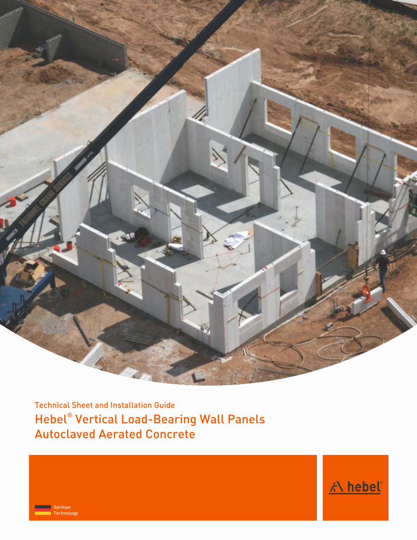
hebel vertical load bearing wall panels
TRANSCRIPT
German Technology
®Hebel Vertical Load-Bearing Wall PanelsAutoclaved Aerated Concrete
Technical Sheet and Installation Guide

About Hebel®
Hebel® is a registered trademark of Xella Group, a German technology. In the USA, we are now part of Bexel International Group, manufacturing Autoclaved Aerated Concrete products, following the highest quality standards of the industry. Hebel® offers the most efficient solution in construction systems, more than 80 years in the market support us. We have been present in America since 1994.
Hebel® is distinguish by being a high-quality, innovative option that combines various properties in a single material. The benefits are reflected from the construction phase, it is up to 5 times lighter than traditional concrete, and has a significant impact on reducing construction time, as well as generating great savings in steel, concrete and labor.
We promote sustainability with high energy efficiency in all types of buildings.
Our systems provide high thermal performance, maximum fire resistance, acoustic insulation and resistance to humidity.
Hebel® is committed to providing to the United States with environmentally responsible building solutions that conserve material an energy usage. We are members ot the Green Building Council.
Hebel® Autoclaved Aerated Concrete offers to contractors with strong, easy-to-install blocks and reinforced panels that are one-third the weight of traditional concrete and replace traditional multi step construction processes.
Our building systems offer low insurance and maintenance cost to the building owner. A wide range of projects can benefit from Hebel® blocks and reinforced panels, including those in the commercial, educational, hospitality, industrial, institutional, governmental and residential segments.
Due to the AAC qualities, Hebel® has national and international recognized certifications, their manufacturing process is carefully monitored at all
stages, in order to guarantee the best quality for our customers.
Its properties take any project to a higher category, managing to build a better quality life, comfort and savings for a lifetime. At Hebel® we care to offer a full experience with a 360 service for each project specification.
The Hebel® Plant is located in Nuevo León, México and its USA offices are located in San Antonio, TX., from where we serve the USA market.

The physical properties of HEBEL Autoclaved Aerated Concrete are unique to any other building material. Properties such as thermal insulation and fire resistance cannot be met by another product alone.
Ÿ Speed of Construction
Ÿ Thermal Insulation & Energy Savings
Ÿ Superior Fire Resistance
Ÿ Sustainable
Ÿ Relatively high strength for a low density
Ÿ Workability
Ÿ Acoustic Performance
Ÿ Precision
Resistance to humidityProtects against moisture. It allows the p a s s a g e o f w a t e r v a p o r , r e d u c i n g condensation.
Green BuildingŸ Recyclable, inert & non-toxicŸ Energy savingŸ DurableŸ LEED credits
Fire ResistantWe are certified by Underwriters Laboratories ( U L ) w i t h t h e m a x i m u m f i r e - r a t i n g classification. Our systems withstand fire exposure up to 4 hours, maintaining their structural integrity and DO NOT emit toxic fumes even under intense heat.
Thermal InsulationBuildings constructed of HEBEL AAC provide substantial energy savings in both hot and cold climates. The unique closed cellular structure and the thermal mass contribute to a high R-value and air-tightness which reduce heating and cooling costs and improve indoor air quality. Buildings have seen savings on air conditioning up to 35% by using HEBEL AAC.
Structural PerformanceResists wind pressures. High impact resistance.
Acoustic InsulationProvides exceptional acoustic insulation. Its porous structure and high surface mass, coupled with its ability to dampen mechanical vibration energy, greatly reduces sound transmission from exterior - interior and room-to-room.
This product meets Standards and Evaluation issued by:
Physical Properties
Benefits
®Aerated Concrete Hebel :Unique properties in a single material.
Easy treatmentCan be easily cut, drilled and grooved with manual or power tools.
LightweightIts lightweight nature allows a faster and more efficient construction.
Pest resistanceNot a food source for termites or vermin and no cavity construction. Eliminates the chance of harbouring pests.

2
14
5
6
6
710
12
Index® Introduction to Hebel Vertical Load Bering
Wall Panel Description ............................................................... Advantages ..............................................................
1 Technical Sheet1.1 Hebel® Vertical Load Bearing Wall Panel ...............
2 Design Considerations2.1 General Considerations ..........................................
3 Installation Guide3.1 General Installation Guidelines...............................3.2 Preparation ............................................................3.3 Wall Panel Installation ...........................................3.4 Panel Cutting ..........................................................
4 Renders and Finishes4.1 Products .................................................................
5 FastenersFasteners .....................................................................
12
33

Uses and applications®Hebel AAC Hebel Vertical Load Bearing
exterior and interior walls for residential, hotels, commercial and modular buildings. The thickness and panel length (height) vary depending on the design requirements and constraints of the project. Construction AdvantagesŸ 4 Hour Fire RatingŸ Moisture ResistantŸ Mold ResistantŸ LightweightŸ Pest and Rot ResistanceŸ Non-Toxic
3
®Hebel Vertical Load-Bearing Wall PanelsAutoclaved Aerated Concrete
Application:Ÿ CommercialŸ ResidentialŸ Industrial
Certifications: UL, IAPMO, TDI.
This product is friendly to the environment, ecological, non-toxic and
sustainable; And also grants LEED points.

German Technology
® Hebel Vertical Load-Bearing Wall PanelsAutoclaved Aerated Concrete

1 TechnicalSheet
1.1 Vertical Load Bearing Wall Phanel
General Features
®Hebel AAC (Autoclaved Aerated C o n c r e t e ) W a l l P a n e l s a r e lightweight, fire resistant, fast and
®easy to install. Hebel AAC Vertical Load-Bearing Wall Panel is a reinforced (Grade 70 steel) element spanning with full story height. The
®Hebel Load Bearing Panel system is based on a standard two feet wide module. The thickness and panel lenght (height) vary depending on the design requirements and constraints of the project.
Uses
®Hebel AAC load bearing Wall Panels are used to build load-bearing and non load-bearing exterior and interior walls for hotels, commercial and any modular buildings.
®Fig. 1: Hebel wall panels packaging.
5
Dimensions
Length:(1) Up to 20 ft.(2)(3) 6, 7, 8, 10 and 12 in.Thickness:
(4) Width: 24 in.
(1)Tolerance ± (2)(4) (3)3/16”, Tolerance ±1/8”, Nominal. Manufactured according to ASTM C1693 / ASTM C1452.
in
6
7
8
Table 3: Hebel® wall panel R-Value.
(1)Note: Nominal dimension, Units: R= Thermal resistance, hi= hour, in= inches, F= Fahrenheit degrees
ft²= square feet, BTU= British thermal unit.
ft² h °F / BTU
Thermal Properties
R-Value
ft² h °F / BTU
R-ValueThickness *
in
10
12
-
Thickness *
10.03
12.03
-
10.79
12.95
-
AAC-6AAC-6AAC-4 AAC-4
6.02
7.02
8.02
6.47
7.55
8.63
Fire Performance
4
Material
Note: Testing performed at underwriters Laboratories, Inc. under ASTM E119 (UL/ANSI 263) “Fire Test of Building Constructions and Materials”.
UL Design NumberFire RatingThickness
®Hebel Bearing Wall Panel
UL Fire ResistanceDirectory 1998
> 6 U920
Hourin
®Table 4: Hebel wall panel, fire rating.
®Table 5: Hebel wall panel acoustic performance.
Note: Testing performed at Acoustic System, Inc., Austin. TX in accordance with ASTM E (90) Standard Method for Laboratory Measurement of Airbome Soung Transmission Loss of Building Partitions.
Acoustic Performance
STC Report Number®Hebel 6” AAC-4 Unifinished®Hebel 8” AAC-6 Unifinished®Hebel 10” AAC-4 Unifinished
Hebel® Wall Panel
44
50
50
AS-TL958AX
AS-TL1026AX
AS-TL978AX
Table 2: Hebel® wall panel design weight.
(1) Nominal dimension, *Exact dimension, **Considering a 24 in panel width.
Design Weight
in
3
3
3
4
4
in
6
7
8
10
12
Groove Diam
in*
5.906
6.889
7.874
9.843
11.811
lb/ft²
22.15
25.84
29.53
36.91
44.29
lb/ft**
44.29
51.67
59.06
73.82
88.58
Design Weight
AAC-4 AAC-6
(1)ThicknessAAC-4 AAC-6
lb/ft²
18.41
21.48
24.56
30.70
36.84
lb/ft**
36.82
42.96
49.12
61.40
73.68
Characteristic
580
31
37
<0.02-64.4 X10
295,800
0.9124
348
Compressive Strength (f'aac)
Nominal Density
Design Weight
Drying Shrinkage
Thermal Expansion Coefficient
Modulus of Elasticity
Thermal Conductivity
Allowable Bearing Stress
Table 1: Physical and design properties.
Unit ACC-4 Class ACC-6 Class
psi
pcf
pcf
%
1/°F
psi
psi
BTU-in/2ft -h°F
870
37
45
<0.02-64.4 X10
377,000
0.9811
523
6
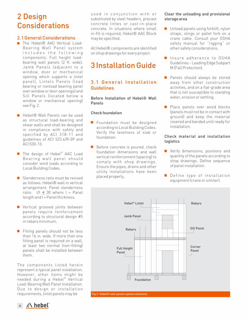
Fig.2: Hebel® wall panels system elements.
2 Design Considerations
2.1 General ConsiderationsŸ The Hebel® AAC Vertical Load-
Bearing Wall Panel system i n c l u d e s t h e f o l l o w i n g components: Full height load-bearing wall panels (2 ft. wide), Jamb Panels (adjacent to a window, door or mechanical opening which supports a lintel panel), Lintels Panels (load bearing or nonload bearing panel over window or door openings) and Sill Panels (located below a window or mechanical opening) see Fig. 2.
Ÿ Hebel® Wall Panels can be used as structural load-bearing and shear walls and shall be designed in compliance with safety and specified by ACI 318-11 and guidelines of ACI 523.4/R-09 and ACI 530-13.
®Ÿ The design of Hebel AAC Load
Bear ing wal l pane l should consider wind loads according to Local Building Codes.
Ÿ Slenderness ratio must be revised as follows: Hebel® wall in vertical arrangement: Panel slenderness ratio: l/t < 30 where l = Panel length and t = Panel thickness.
Ÿ Vertical grooved joints between panels require reinforcement according to structural design #5 in rebars minimum.
Ÿ Fitting panels should not be less than 16 in. wide. If more than one fitting panel is required on a wall, at least two normal (non-fitting) panels shall be installed between them.
The components l isted herein represent a typical panel installation. However, other items might be
®needed during a Hebel Vertical Load-Bearing Wall Panel Installation. Due to des ign or insta l la t ion requirements, lintel panels may be
u s e d i n c o n j u n c t i o n w i t h o r substituted by steel headers, precast concrete lintes or cast-in-place concrete. In situations where small in-fill is required, Hebel® AAC Block may be specified.
All Hebel® components are identified on shop drawings for every project.
3 Installation Guide
3.1 General Insta l la t ion Guidelines
Before Installation of Hebel® Wall Panels
Check foundation
Ÿ Foundation must be designed according to Local Building Codes. Verify the levelness of slab or foundation.
Ÿ Before concrete is poured, check foundation dimensions and wall vertical reinforcement (spacing) to comply with shop drawings. Ensure the pipes, drains and other utility installations have been placed properly.
Clear the unloading and provisional storage area
Ÿ Unload panels using forklift, nylon straps, slings or pallet fork on a crane cable. Consult your OSHA safety manual for “rigging” or other safety considerations.
Ÿ Insure adherence to OSHA Guidelines - Leading Edge Subpart M (Fall Protection).
Ÿ Panels should always be stored away from other construction activities, and on a flat-grade area that is not susceptible to standing water, erosion or settling.
Ÿ Place panels over wood blocks (panels must not be in contact with ground) and keep the material covered and banded until ready for installation.
Check material and installation logistics
Ÿ Verify dimensions, positions and quantity of the panels according to shop drawings. Define sequence of panel installation.
Ÿ Def ine t ype o f ins ta l la t ion equipment (crane or similar).

7
Ÿ Evaluate quantity of personnelrequired.
Ÿ Set delivery schedule to match theerection sequence. Excessivehandling of Hebel® AAC panelsmay damage the element.
Ÿ Chips and spalls can be repaired. Ifany panel reinforcing is visible,contact an autorized Hebel® AACrepresentative.
Ÿ All damaged surface areas may berepaired using a compatibleHebel® AAC patching compound.
Ÿ Hebel® AAC panels that havesurface or minor cracks areusable. Contact an authorizedHebel® AAC representative whencracks extend completely throughthe panel.
Check for material, tools and equipment Available for purchase from Litecrete, Inc.
Ÿ Hebel® Thin-bed MortarŸ Hebel® Repair MortarŸ Corrugated NailsŸ Hebel® Nails (4” or 6”)Ÿ WKV Lifting Clamp[For Rent]Ÿ Helifix Anchors (8mm)Ÿ Mortar Trowel
Provided by the Contractor / OwnerŸ Temporary BracingŸ Crane and AccessoriesŸ Fine Grout Mortar.Ÿ Nails, threaded rod, nut, couples,
washers, etc.Ÿ 6 ft. Carpenter's LevelŸ ½”Ø A370 Thru-boltsŸ Choker & ShackleŸ Mixing Tub / PaddlesŸ Wood Guide TemplatesŸ Reinforcing Bars
Ÿ Rebar BenderŸ Tape measure, chalk-lineŸ Trubolt wedge anchorsŸ Wakai Hit Nails [6 x 110 mm]
3.2 Preparation
Shop DrawingsShop Drawings include the following information: Wall panel layout, wall elevations, sections and details, general notes, revision date and number, panel schedule indicating panel number (see Fig. 4), quantity of panels and dimensional information (length, width and thickness).
Review shop drawings and ensure that everyone is using the latest version (see revision number). Drawings must be approved for construction in order to begin panel installation.
Panel IdentificationEvery panel can be easily identified by a reference number
( p r o j e c t n u m b e r ) a n d p a n e l information printed on one end-side of the panel. See panel schedule and drawings to corroborate dimensions and to determine its final position.
Lifting Equipment Hebel® Lifting Clamp Type WKV(Manufactured by Van de Blij B.V.)
T h e W K V c l a m p i s d e s i g n e d specifically for vertical and horizontal (lintels) installation of Hebel® wall panels. The clamp has a constant clamp force lock (torque wrench principle).
Fig. 3: Hebel® Load Bearing Wall panels.
Fig. 5: WKV Lifting Clamp and Manometer.
Fig. 4: Hebel® wall panels indentification.
Specifications
Concept (1)Clamp
WKV 15-20Clamp Type
Fixed Internal Height
Clamp Lenght
Clamp Range
Max. Load Bearing Capacity
Weight
Pressure (2)(1)Supplied stan with manometer to check clamp press ure. (2) Clamp pressure must be within the acceptable range.
Table 6: WKV lifting clamp specifications.
WKV 20-25
260 in
200 in
6" to 8"
(15-20 cm)
1,540 lb (700 kg)
8" to 10"
(20-25 cm)
1,650 lb (750 kg)
220 lb (100 kg)
110 < bar Clamp Pressure <140 bar

8
Every day, before using the clamp, check the clamp pressure using the pressure cylinder (manometer) and record the reading in the log. Important: Each manometer is dedicated to a specific lifting clamp type. Verify the lifting and manometer shipped has the same identification numbers. Test the lifting clamp pressure at least twice every day prior to start of panel installation (start of the day and at the mid-day). The clamp pressure should be as follows:
110 bar < Clamp Pressure < 140 bar
If the pressure is either lower or higher than the values in the range, the clamp must be checked by an authorized service representative.
If the manometer shows the correct pressure, you may use the clamp. Record the details in the log and keep the log with the manometer and the clamp. The pressure must be recorded in the log daily.
Template Layout
The purpose of the template is to establish a true and square plan within the building perimeter and to determine control points around the building in order to assess the accuracy of panel placement as installation progresses.
Suggested Material and Equipment (Included but not limited)
Ÿ 2” x 4” high grade lumber for use as a panel template guide.
Ÿ Level or Transit-Level.Ÿ Masonry screws (Hilti KWIK-CON
II or ITW Tapcon)Ÿ 2” x 4” wood cleats.Ÿ Chalk-line, tape measure, etc.Ÿ Metal square.
Fig. 8: Place cleats every 4 ft. and perpendicular to wall lines. (secure cleats with masonry screwsHilti, ITW Tapcon or similiar).
Fig. 9: Place template (elevated) on cleats to allow uniform distribution of mortar bed. Aligntempleate to building wall lines.
Note: All slabs which are intended to remain exposed at the completion of the project must be protected with felt paper (30# min) to p r e v e n t s t a i n i n g f r o m mortar droppings.
Fig. 6: Check the levelness of the slab prior to installing the template.
Fig. 7: Trace building wall lines. Check alignment and square. Snap chalk-line on slab along the inside face of the wall panels.
Template Installation
Fig. 10: Identify openings on tamplate.Fig. 11: Indicate panel number, door & windows openings, mechanical opening, etc.

9
Fig. 13: Bracing type specification for wall height >12 ft.
Fig. 12: Bracing type specification for wall height ≤12 ft.
Note:Temporary bracing shall remain in place until shear key grouting (verti-cal joints), floor or roof system and concrete bond beams have been com-pleted and at least 24 hours old.
1
2
2’-0”
E5
E4
E3
2/3 PANEL HEIGHT
Note:Temporary bracing shall remain in place until shear key grouting (verti-cal joints), floor or roof system and concrete bond beams have been com -pleted and at least 24 hours old.
1
1
E3
E2
E1
E1
E2
Temporary BracingThe temporary bracing used for the installation of Hebel® Vertical Load Bearing Wall Panels may be accomplished is accordance with the following schedules:
Schedule “B”
Wind Speed: 50 mph(1)Wind Load (w) =0.00256V²
Wind Pressure (w): 6.4 psf(1)The wind load criteria is in accordance with the ìStandard Practice for
Bracing Masonry Walls under Constructionî.
Table 7: Bracing specifications (wind load).
Schedule “A”
Wind Speed: 40 mph(1)Wind Load (w) = 0.00256V²
Wind Pressure (w): 4.1 psf
Table 8: Bracing type spacification for wall height ≤ 12 ft.
Table 9: Bracing type spacification for wall height > 12 ft.
Wall Height < 12´-0"See Fig. 12
Wall Height > 12´-0"See Fig. 13
2”x4” - “T-Brace” with 10dcommon nails @ 12 in OC
and installed @ 6 ft OC (walls& openings < 6 ft wide). Foropenings > 6 ft wide, provide
bracing @ each side.
Fasten top of Pipe-Bracing @ 6 ft OC with (1) 1/2” Ø A307 Thru-Boilt Use a 1/4”x5”x 5” plate washer on the outside wall surface.
Schedule “B”
Schedule “B”
Schedule “A”
Schedule “A”
E1
E4
Ele
me
nt
Ele
me
nt
E2
E5
E3
E3
2”x4” - “T-Brace” with 10dcommon nails @ 12 in OC
and installed @ 4 ft OC (walls& openings < 4 ft wide). Foropenings > 4 ft wide, provide
bracing @ each side.
2”x4”x12” Cleat fasten to concrete slab with (2) 1/4” Ø x 3 1/4” tapcons.
Fasten to Hebel® wall/floor panels with (3) 6x1 10Wakai Hit nails or (2) Hebel® AAC nails (4” or 6” long.) (Note: Pre-drill 1/4” holes
through wood cleats for Wakai Hit nails or Hebel® AAC Nails)
Fasten “T-Brace” to cleat with (3) 16d sommon nails.
Fasten bottom of Pipe-Bracing to concrete slab with (1) 1/2” ØITW Trubolt wedge anchor w/ (1) 2 1/4” embed. Fasten to Hebel®
floor panels w/(1) 1/2” Ø A307 Thru-BoltUse a 1/4”x5”x5” platewasher on the bottom floor surface.
2”x 4” lumber continuos with 12d common nails @ 5 in.or Hebel® AAC nails @ 10 in.
2”x4” lumber continuos with Hebel® AAC nails @ 8 in.
Note: All bracing material shall be Southern Pine (construction grace).Temporary bracing shall remain in place unitl shear key grouting (verticaljoints), floor or roof system and concrete bond beams havebeen completedand at least 24 hours old.
Design Pipe-Bracing for aMaximum Load = 700 lb(Tension/Compression)
Design Pipe-Bracing for aMaximum Load = 1000 lb(Tension/Compression)
Temporary bracing shall remain in place until shear key grouting(vertical joints), floor or roof system and concrete bond beams have beencompleted and at least 24 hours old.

10
3.3 Wall Panel Installation
Vertical Lifting and Installation
1. Identify the panel that will be laid according to previous logistics and template layout (see section 3.2).
2. Unpack panels. Verify panels are in a stable position prior to cutting the banding (see Fig. 14).
3. Check spacing of vertical reinforce-ment between panels.
4. Prepare thin bed mortar to be used on setting the fist row of panels and on joints between panels.
5. Attach clamp to crane hook.
6. Move the clamp to the end of the wall panel to be lifted.
7. Open the clamp sufficiently, depen-ding on the thickness of the wall panel, by turning the hand wheel counterclockwise.
8. Rotate the clamp 90° on the handle so that tha jaws of the clamp point toward the wall panel. The jaws of the clamp must be placed in the center of the wall panel.
9. Set the clamp with the inner side of the clamp fully against the wall panel (see Fig. 15).
10. Apply pressure to the clamp by turning the hand wheel of the clamp clockwise until you feel a “click” and the green windows (on clamp wheel face) are visible (do not turn it anyfurther after this).
11. First panel: Prior to lifting a vertical panel with the clamp, apply Hebel® thin bed mortar on slab for installing the first row of panels and 10 minutes (maximum) from final sett ing of panel (see Fig. 16). Subsequent panels: Apply Hebel® thin bed mortar on slab for insta- lling the first row of panels and on vertical joint between panels (width of panels) 10 minutes (max) from final setting of panel (see Fig. 16 & 17).
Use Hebel® mortar trowel to ensure an even and consistent application of thin bed mortar (see Fig. 17).
12. Carefully hoist the wall panel up and maneuver it into position. Panel rotates to vertical position for panel installation (see Fig. 18).
13. The panel is lowered at its final position, stabilized and guided into place by installer. Always plumb the panel with a 6 ft level prior to being “nailed off” with (2) corrugated nails on top of flat joints between panels and bracing installation (see Fig. 19 to 22). Use shim plates if necessary.
14. Install temporary bracing accor-ding to section 3.2. Temporary bracing shall remain in place until concrete bond beam and shear key grouting is complete and floor slabs or roof panels are already installed (see Fig. 12 & 13).
Fig. 14 Fig. 15 Fig. 16
Fig. 18Fig. 17

11
15. When the wall panel has been positioned correctly, the clamp can be removed from the panel by opening the clamp sufficiently. Do this by t u r n i n g t h e h a n d w h e e l counterclockwise (see Fig. 22).
16. Clamp is released and returning to lift next panel from staging area (steps 6 to 15 -subsequent panels-).
17. Procede to pour fine grout mortar into cells (joints between panels) to complete instalation. Allow the escape of trapped air by drilling a hole (½”) at the bottom of cells (6” above slab).
18. Approximately 30 minutes after panels are set in place, scrap the excess mortar from all the joints. Clean up the excess mortar and dispose of properly or use it for patching.
19. Patching of minor chips and spalls should occur inmediately following scrapping of the excess mortar from the walls. All interior wall joints should be skim coated with Hebel® thin-bed mortar as part of the surface preparation for the interior finishes.
20. Remove all wall templates from the slab the day after the panels have been installed and bond beams completed. Scrap away and remove all excess mortar at bed joints.
Fig. 19
Fig. 20
Fig. 21
Fig. 22
Fig. 23

12
Horizontal Lifting andInstallation
21.Mark the center of the wall panel (lintel) to be lifted.
22. Open the clamp, lower it completely on the panel at the marked centerline and apply pressure to close the clamp.
23.Now carefully hoist the wall panel up and maneuver it into its final position. Apply thin bed mortar to adjacent panels (joints) before lintel setting.
24.When the wall panel (lintel) has been positioned correctly, the clamp can be removed from the panel by opening the clamp sufficiently. Do this by turning the hand wheel conterclockwise.
3.4 Panels Cutting
According to shop drawings, identify Hebel® Load-bearing Wall Panels to be cut. Hebel® panels can be cut to length to fit openings (jamb panels, sill panels, etc.) or frame heights.
Permissible cutting lengths are a function of the project dimension. Along its length, Hebel® wall panels can be cut 1/3 the width:
Cutting equipment options:
Ÿ Power Cutter (gasoline-powered) 14", 16" diamond blade or greater (see Fig. 25).
Cutting procedures:
Important: Wear work gloves, protective helmet & visor, goggles, hearing and respiratory protection. Do not smoke or work near open fires. Read equipment instruction manual.
a) Prepare a flat surface for cutting site.
b) Check dimension of cuts to be made.
c) For transversal cuts, wood pieces must be placed along the sides of the cut and at the edges of the panel.
d) For longitudinal cuts, wood pieces must be placed at every 9 ft. minimum for 6 to 12 in thick panels and at every 6 ft. for panels 4 to 5 in thick.
e) Check for full contact between wood pieces and panel. Wedge if necessary.
f) Place a ruler as a guide and trace the cut dimensions.
g) Proceed with panel cutting, veri-fying that cutting dimensions comply with specifications. Transversal cuts can be performed with panel in vertical position using groove edge as suport. Longitudinal cuts must be made with panel in horizontal position; if full thickness is to be cut, perform cut from both sides.
h Apply anticorrosive paint to the exposed rebar tips.
4 Renders and Finishes
4.1 Products
Most finish systems for exterior AAC (Autoclaved Aerated Concrete) load bearing walls panels consist of three main components: base coat , reinforcing mesh, and a finish coat.
Fig. 24: Lintel installation.
Fig. 25: Cut panels using a gasoline-powered circular saw.
IMPORTANT Ÿ Check the clamp pressure with the special test-cylinder every day before
using.Ÿ Tampering with the clamp is not permitted. The clamp has been calibrated
in the factory.Ÿ It is strictly forbidden at any time for people to be under the load during
lifting.Ÿ The maximum load-bearing capacity of the clamp may never be exceeded.Ÿ Never put hands, arms, feet, head or legs under the load, or between the
jaws of the clamp.Ÿ The load must always be hoisted; it may not be dragged along the ground.Ÿ Avoid sudden movement to prevent accidental release of the load.Ÿ In freezing weather, do not attempt to lift panels on which ice has formed.

13
Surface preparation: Rasp joints and other areas where the Hebel® AAC surface is out of plane to a smooth in-plane surface. Surface must be clean, free of dirt, oil and any other foreing matter. Loose or damaged material must be removed. Apply a tinted primer (acrylic based) in case of acrylic base-coats.
Hebel® Base-Coat: Apply a layer (¼” thickness minimum) of Hebel® Base Coat (cement-based or acrylic) or a c r y l i c b a s e - c o a t s ( H e b e l ® , products or similar), according to manufacturer instructions. Reinforce base-coat using Fiberglass mesh embedded in 100% of the surface area (see Fig. 26).
Finish Coat: Apply ready-mix acrylic based products or elastomeric paints as decorative and protective finish coat -top-coat- (Sto AAC products or similar).
Apply finish directly over the primed wall surface. Apply finish by spraying or troweling with a stainless steel trowel, depending on the finish specified (see Fig. 26). Fig. 27: Five-story hotel built with Hebel® AAC load bearing Wall Panels.
Fig. 26: Exterior and interior finish options on load bearing wall panels.
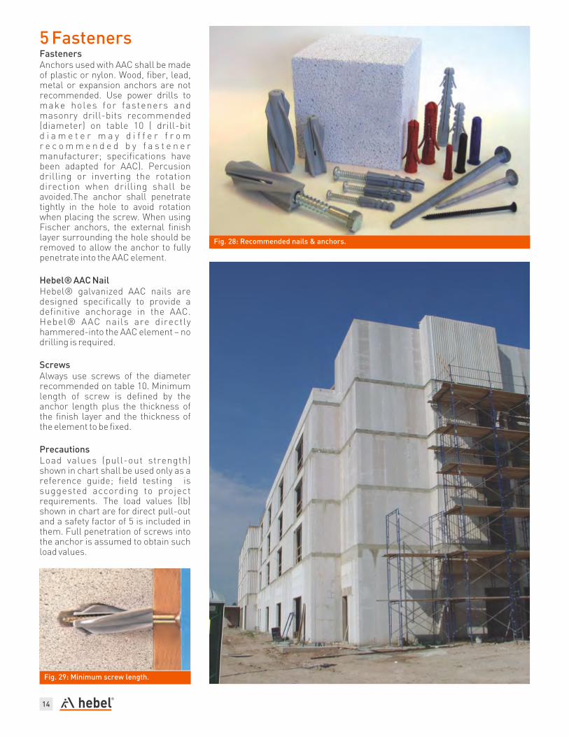
5 FastenersFastenersAnchors used with AAC shall be made of plastic or nylon. Wood, fiber, lead, metal or expansion anchors are not recommended. Use power drills to make holes for fasteners and masonry drill-bits recommended (diameter) on table 10 ( drill-bit d i a m e t e r m a y d i f f e r f r o m r e c o m m e n d e d b y f a s t e n e r manufacturer; specifications have been adapted for AAC). Percusion drilling or inverting the rotation direction when drilling shall be avoided.The anchor shall penetrate tightly in the hole to avoid rotation when placing the screw. When using Fischer anchors, the external finish layer surrounding the hole should be removed to allow the anchor to fully penetrate into the AAC element.
Hebel® AAC NailHebel® galvanized AAC nails are designed specifically to provide a definitive anchorage in the AAC. Hebel® AAC nails are directly hammered-into the AAC element – no drilling is required.
ScrewsAlways use screws of the diameter recommended on table 10. Minimum length of screw is defined by the anchor length plus the thickness of the finish layer and the thickness of the element to be fixed.
Precautions Load values (pull-out strength) shown in chart shall be used only as a reference guide; field testing is suggested according to project requirements. The load values (lb) shown in chart are for direct pull-out and a safety factor of 5 is included in them. Full penetration of screws into the anchor is assumed to obtain such load values.
Fig. 29: Minimum screw length.
Fig. 28: Recommended nails & anchors.
14

15
Fasteners & NailsAutoclaved Aerated ConcreteTechnical Sheet
®Hebel AAC Nails
(3)Hebel AAC Nail 4 in.
Min. Penetration: 3 in.(3)Hebel AAC Nail 6 in.
Min. Penetration: 5 in.
Universal Plastic Anchor
Anchor TP 14 - 1/4"
Anchor TP 56 - 5/16"
Anchor TP 38 - 3/8"®Note: For use in solid walls (Anclo or similar).
®THORSMAN
[4]Anchor Red TP 2X
®TOX VLF
®HILTI Plastic Anchors
(4)Anchor HUD-1 (10x50)
(4)Anchor HUD-1 (12x60)
More Products: www.us.hilti.com
®FISCHER
(3)Anchor GB 10
drill bit. *Safety Factor [SF]=5. Use masonry drill bits.Anchors do not
include screws (except TOX anchors).
IMPORTANT: Information has been adapted considering Autoclaved
Aerated Concrete (AAC) material and may differ from original fastener
manufacturer.
GB14
GB10
S10H80R
Anchor / Nail
Length
in
Ø Diam
Ø in
Drill Bitfor Masonry
ScrewLoad Value*
(pull-out strength)
in Ø in Lb Lb
AAC-6Panel
AAC-4Block
Available at Litecrete, Inc.
4"
6"
1/4"
5/16"
Fixeddirectly
withhammer
Not Required
Not Required
51
88
88
137
Available at Construction Depots
Available at Construction Depots
Available at www.demandproducts.com
Available at Hilti Shops and Construction Depots
Available at Litecrete, Inc.
2" 3/8"3/8"
1/2"
5/8"
3/8"
1/4"
1/4"
3/8"
5/16"
126
---
165
123
---
104
225
150(3)Anchor S10H80R
(3)Anchor GB 14 3" 5/8"
3/8"
2"
1 ”
1½”
1 ”
2 ”
3/8"
1/2"
3/8"
7/16"
5/16"
3/8"
71
128
90
185
1/4"
5/16"
3/8"
Anchorwith screws
inluded (pre-
assembled)
No pre-drilling forAAC-4 Class
66
102
120
---
---
---
(5)Anchor 6/70 (5)Anchor 8/80 - 8/135
(5)Anchor 10/100 - 10/160
1/4"
5/16"
3/8"
[4]Anchor Brown TP 2B [4]Anchor Blue TP 3
1 ”
1½”
2"
1/4"
5/16"
3/8"
1/4"
5/16"
5/16"
#10
#12
1/4"
22
26
44
26
31
62
1/4"3/16"
1/4"
1/4"
5/16"
5/16"
3/8"
#8
#10
#10
#12
37
---
49
73
---
42
62
84
3 8
3 8
3 4
3 42 ”
3 ”+
4"+
®Table 7: Anchoring into Hebel Vertical Load-Bearing Wall Panels.
3 ”3 8
Dry Wall Screw
8 x 3"
8 x 2½”
Not Required
3"
2½”
-
-
Available at Construction Depots
Not pre-drillingis required
35
33
57
44
(1) (2)Notes: Anchors without screws, except TOX VLF anchors. Drill bit
diameter change between AAC-4 y AAC-6 classes. (4) Notes: Available at Litecrete, Inc. Available at Hilti Shops, Home
(5) (6)Depot,Lowe's, etc. Available at www.demandproducts.com For AAC-6 (7)(Block & Panel) use 1/4” drill bit. For AAC-6 (Block & Panel) use 1/2”
(3)

/Hebel Building Solutions “Heb
el”
® Is
a r
egis
tere
d tr
adem
ark
of th
e Xe
lla G
roup
, Ger
man
y.
Contact us
Litecrete, Inc.833 Isom Rd. San Antonio, TX 78216
Phone (210) 402-3223 Fax (210) 402-6390
ww.hebel-usa.com