heidelberg prosetter - xitron
TRANSCRIPT
Xitron Part Number Doc-1118-0710
Plug-in Manual
Heidelberg ProSetter
Version 7.5.0.1 March 9, 2011

3/9/2011 Xitron Plug-in Manual Page 2
Xitron’s Navigator PostScript RIP and Raster Blaster TIFF Catcher rely on software modules called plug-ins to communicate with imaging systems. In many cases they work in tandem with an interface card, while in others it is simply a conversion to a bitmap file in a compatible format. When interface cards are involved, these plug-ins act as device drivers and control most actions of the output devices. Some of these actions include checking device status, device setup, and advancing and cutting material. In addition, the plug-in relays all the physical characteristics of an engine such as supported resolutions and imageable area. During the launch sequence, both Navigator and Raster Blaster scan a specific directory for plug-ins. The software loads each plug-in it finds, and then queries them for a description of the capabilities of the supported devices. In this manner the plug-in configures the RIP to output a bitmap to these devices. Each plug-in controls a particular family of recorders and is able to understand most messages and errors communicated by the output device. Plug-ins for use with Windows-based platforms consist of three software modules. The first module is the core plug-in written specifically for a particular device. This DLL is 32-bit code and runs under Windows 2003 Server, Windows XP, Windows Vista Business, Windows 2008 Server and Windows 7. The second module is a kernel mode device driver. This module communicates with the Xitron interface boards and moves the bitmap data from the PC to the output device's interface. The third module is a “helper” DLL that translates calls from the plug-in to the Windows device driver. When a page is sent to an output device for imaging, the Xitron software loads the correct plug-in and begins a series of steps prior to output. The plug-in first initializes the engine and checks that it is ready. After receiving the proper signal, the plug-in will begin reading bitmap data from the platform's hard drive into a “printer buffer.” Once the printer buffer is full, the plug-in will start communicating the data to the output device. As the output device consumes the data, the plug-in relays this information to the software, which then refills the buffer. This continues until all of the data has been communicated to the output device. The plug-in tells the software the job is complete and waits for an indicator that the recorder has finished. This process is repeated for each page being output.
Raster Blaster Plug-ins used by Xitron's Raster Blaster have the same functionality as those for the Navigator RIP and the same options are available for configuration. Therefore, unless otherwise specified, the information in this manual will apply to both products. See the Raster Blaster Reference Manual for specific configuration information.
3/9/2011 Xitron Plug-in Manual Page 3
Installation Ensure the ProSetter and the Xitron interface (blue box) are both powered off before connecting the network cable between the two devices. This is critical! The interface chips used for this application are very sensitive and easy to damage if they are connected or disconnected with power applied to the circuit. If it becomes necessary to disconnect the blue box from the cable, POWER DOWN the ProSetter first. Make sure you are using a Cat5 or Cat6 cable that meets the specifications. It should be shielded and rated to 350 MHz. Typically, the jacket is cut back on the cable where it goes into the back of the ProSetter and the shielding is bonded to the chassis. This is recommended for optimum performance.
Test Connectivity
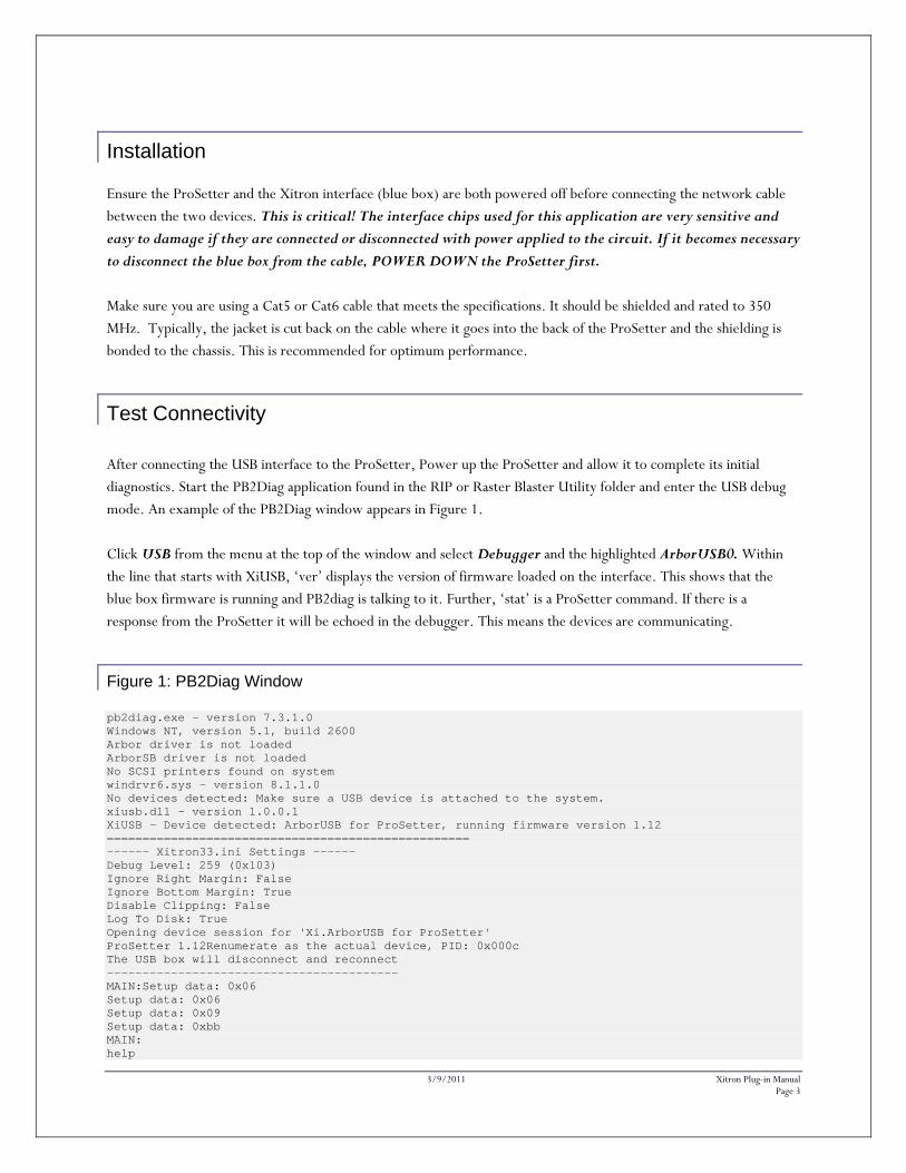
After connecting the USB interface to the ProSetter, Power up the ProSetter and allow it to complete its initial diagnostics. Start the PB2Diag application found in the RIP or Raster Blaster Utility folder and enter the USB debug mode. An example of the PB2Diag window appears in Figure 1. Click USB from the menu at the top of the window and select Debugger and the highlighted ArborUSB0. Within the line that starts with XiUSB, ‘ver’ displays the version of firmware loaded on the interface. This shows that the blue box firmware is running and PB2diag is talking to it. Further, ‘stat’ is a ProSetter command. If there is a response from the ProSetter it will be echoed in the debugger. This means the devices are communicating.
Figure 1: PB2Diag Window pb2diag.exe - version 7.3.1.0 Windows NT, version 5.1, build 2600 Arbor driver is not loaded ArborSB driver is not loaded No SCSI printers found on system windrvr6.sys - version 8.1.1.0 No devices detected: Make sure a USB device is attached to the system. xiusb.dll - version 1.0.0.1 XiUSB - Device detected: ArborUSB for ProSetter, running firmware version 1.12 =================================================== ------ Xitron33.ini Settings ------ Debug Level: 259 (0x103) Ignore Right Margin: False Ignore Bottom Margin: True Disable Clipping: False Log To Disk: True Opening device session for 'Xi.ArborUSB for ProSetter' ProSetter 1.12Renumerate as the actual device, PID: 0x000c The USB box will disconnect and reconnect ----------------------------------------- MAIN:Setup data: 0x06 Setup data: 0x06 Setup data: 0x09 Setup data: 0xbb MAIN: help
3/9/2011 Xitron Plug-in Manual Page 4
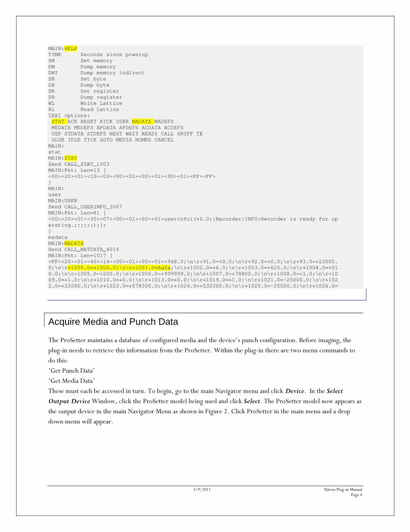
MAIN:HELP TIME Seconds since powerup SM Set memory DM Dump memory DMI Dump memory indirect SB Set byte DB Dump byte SR Set register DR Dump register WL Write Lattice RL Read Lattice TAXI options: STAT ACK RESET KICK USER MADATA MADEFS MEDATA MEDEFS APDATA APDEFS ACDATA ACDEFS UZP STDATA STDEFS NEXT WAIT READY CALL SNIFF TE GLOB IDLE TICK GOTO MEDIA NOMED CANCEL MAIN: stat MAIN:STAT Send CALL_STAT_1003 MAIN:Pkt: Len=13 [ <00><20><01><10><03><00><01><00><01><90><01><FF><FF> ] MAIN: user MAIN:USER Send CALL_USERINFO_3007 MAIN:Pkt: Len=81 [ <00><20><01><30><07><00><01><00><01>userinfo{(+0.0;:Recorder:INFO:Recorder is ready for op erating.;;;;;;);}; ] madata MAIN:MADATA Send CALL_MATDATA_4014 MAIN:Pkt: Len=1017 [ <FF><20><01><40><14><00><01><00><01>+968.0;\n\r+91.0=+0.0;\n\r+92.0=+0.0;\n\r+93.0=+23000. 0;\n\r+1000.0=+1000.0;\n\r+1001.0=Agfa;\n\r+1002.0=+6.0;\n\r+1003.0=+625.0;\n\r+1004.0=+51 0.0;\n\r+1005.0=+200.0;\n\r+1006.0=+999999.0;\n\r+1007.0=+78800.0;\n\r+1008.0=+1.0;\n\r+10 09.0=+1.0;\n\r+1010.0=+0.0;\n\r+1013.0=+0.0;\n\r+1019.0=+1.0;\n\r+1021.0=-25000.0;\n\r+102 2.0=+22000.0;\n\r+1023.0=+578300.0;\n\r+1024.0=+532000.0;\n\r+1025.0=-25000.0;\n\r+1026.0=
Acquire Media and Punch Data The ProSetter maintains a database of configured media and the device’s punch configuration. Before imaging, the plug-in needs to retrieve this information from the ProSetter. Within the plug-in there are two menu commands to do this: ‘Get Punch Data’ ‘Get Media Data’ These must each be accessed in turn. To begin, go to the main Navigator menu and click Device. In the Select Output Device Window, click the ProSetter model being used and click Select. The ProSetter model now appears as the output device in the main Navigator Menu as shown in Figure 2. Click ProSetter in the main menu and a drop down menu will appear.
3/9/2011 Xitron Plug-in Manual Page 5
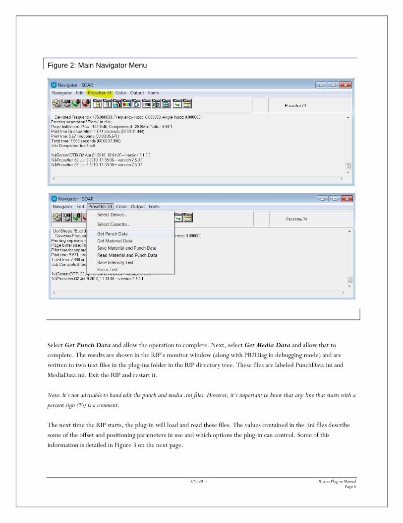
Figure 2: Main Navigator Menu
Select Get Punch Data and allow the operation to complete. Next, select Get Media Data and allow that to complete. The results are shown in the RIP’s monitor window (along with PB2Diag in debugging mode) and are written to two text files in the plug-ins folder in the RIP directory tree. These files are labeled PunchData.ini and MediaData.ini. Exit the RIP and restart it. Note: It’s not advisable to hand edit the punch and media .ini files. However, it’s important to know that any line that starts with a
percent sign (%) is a comment.
The next time the RIP starts, the plug-in will load and read these files. The values contained in the .ini files describe some of the offset and positioning parameters in use and which options the plug-in can control. Some of this information is detailed in Figure 3 on the next page.
3/9/2011 Xitron Plug-in Manual Page 6
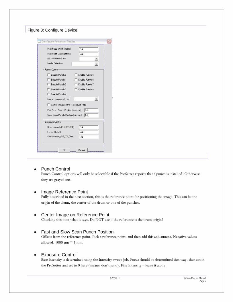
Figure 3: Configure Device
Punch Control Punch Control options will only be selectable if the ProSetter reports that a punch is installed. Otherwise they are grayed out.
Image Reference Point Fully described in the next section, this is the reference point for positioning the image. This can be the origin of the drum, the center of the drum or one of the punches.
Center Image on Reference Point Checking this does what it says. Do NOT use if the reference is the drum origin!
Fast and Slow Scan Punch Position Offsets from the reference point. Pick a reference point, and then add this adjustment. Negative values allowed. 1000 μm = 1mm.
Exposure Control Base intensity is determined using the Intensity sweep job. Focus should be determined that way, then set in the ProSetter and set to 0 here (means: don’t send). Fine Intensity – leave it alone.

3/9/2011 Xitron Plug-in Manual Page 7
Centering and Image positioning To coordinate the position of an image on plate, the operator must first choose a point of reference.
1. The choices are: a. Drum origin (left most point). b. Drum mid point c. One of the punches (of the ones that are available)
2. What location in the image to measure from the reference point.
a. Use the upper left corner of the image b. Use the center of the image in the slow scan direction (This is probably most useful if the reference
point is the drum mid-point.)
3. Add any adjustments for where the image starts, relative to the reference point in the fast scan and slow scan directions. The units are micrometers, or 1/1000th of a millimeter, because that’s what the ProSetter speaks. Negative values are allowed and even encouraged.
The simplest setup is probably to select the drum origin (left most point) as the reference point and the upper left corner of the image, adding any positive or negative offset to that.
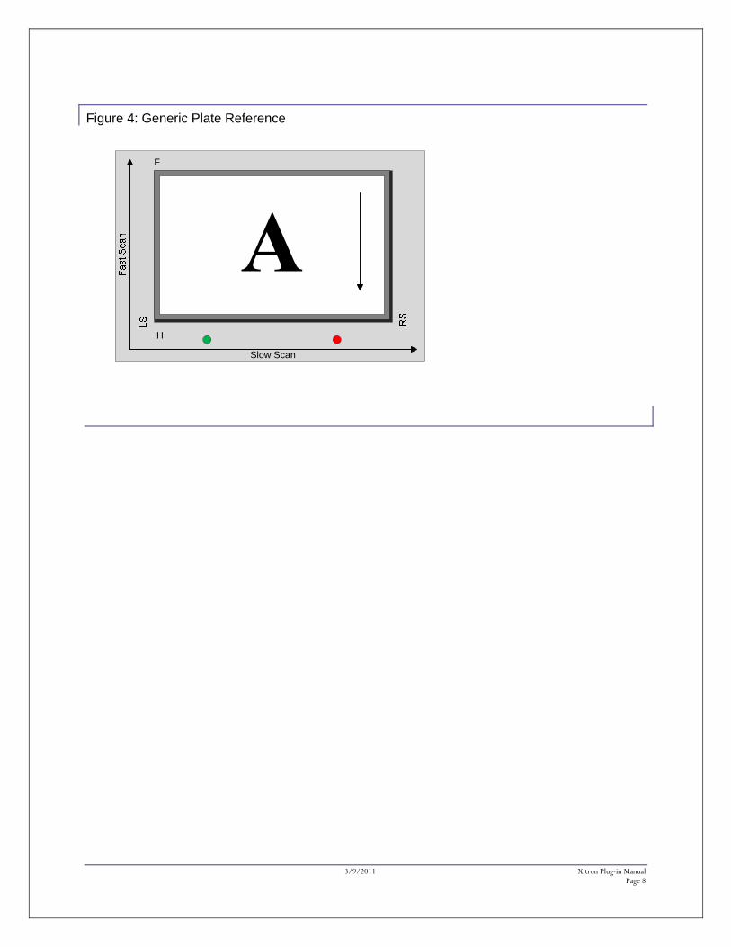
Reference Point Diagrams The following pages have diagrams of the 6 possible image positioning choices. They follow the descriptions above (1a, 1b, 1c, each with 2a; 1a, 1b, 1c, each with 2b): The first diagram (Figure 4) is a generic reference to point out fast and slow scan directions, head and foot (H & F), and left side and right side of the plate.
3/9/2011 Xitron Plug-in Manual Page 8
Figure 4: Generic Plate Reference
Slow Scan
F
H
3/9/2011 Xitron Plug-in Manual Page 9
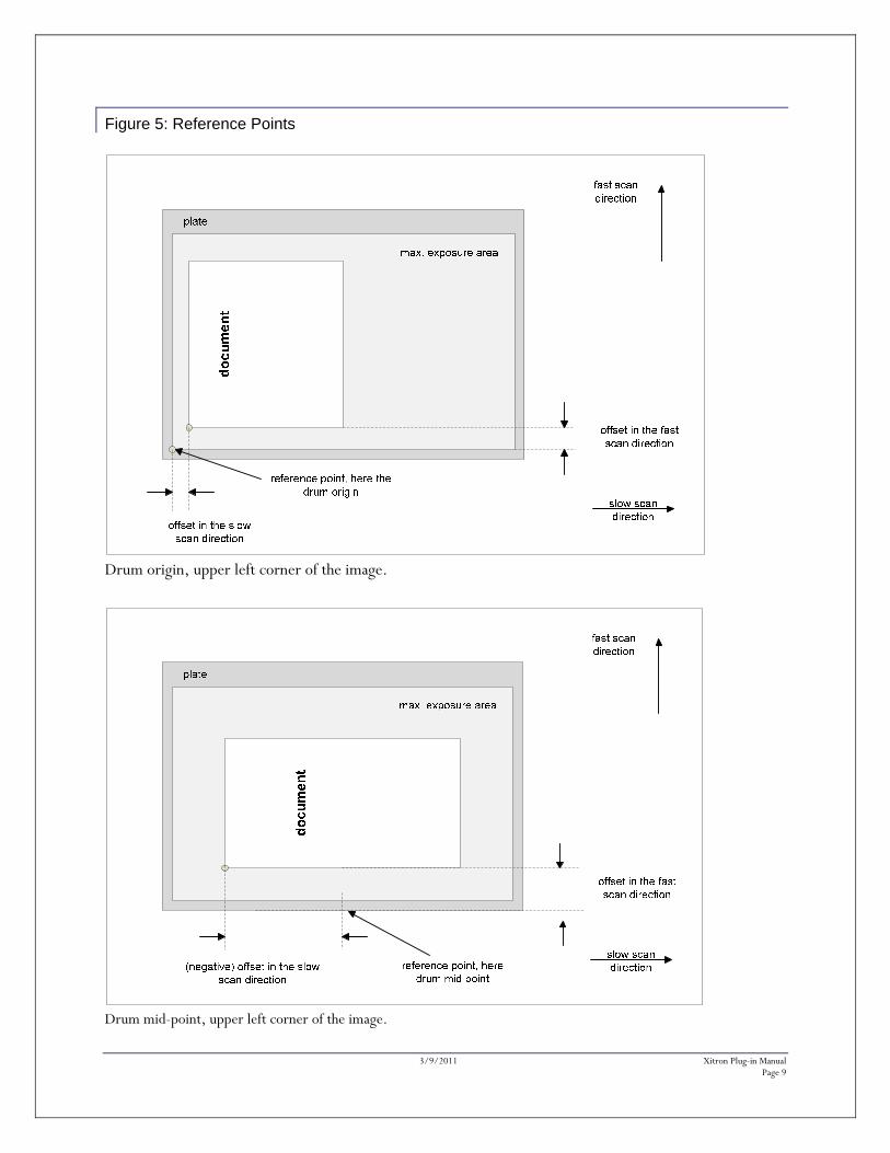
Figure 5: Reference Points
Drum origin, upper left corner of the image.
Drum mid-point, upper left corner of the image.
3/9/2011 Xitron Plug-in Manual Page 10
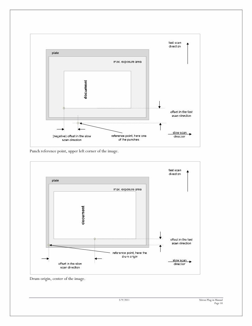
Punch reference point, upper left corner of the image.
Drum origin, center of the image.
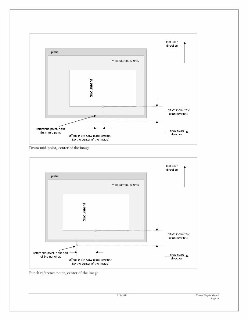
3/9/2011 Xitron Plug-in Manual Page 11
Drum mid-point, center of the image.
Punch reference point, center of the image
3/9/2011 Xitron Plug-in Manual Page 12
Intensity and Focus
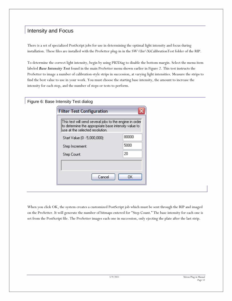
There is a set of specialized PostScript jobs for use in determining the optimal light intensity and focus during installation. These files are installed with the ProSetter plug-in in the SW\Usr\XiCalibrationTest folder of the RIP. To determine the correct light intensity, begin by using PB2Diag to disable the bottom margin. Select the menu item labeled Base Intensity Test found in the main ProSetter menu shown earlier in Figure 2. This test instructs the ProSetter to image a number of calibration-style strips in succession, at varying light intensities. Measure the strips to find the best value to use in your work. You must choose the starting base intensity, the amount to increase the intensity for each step, and the number of steps or tests to perform.
Figure 6: Base Intensity Test dialog
When you click OK, the system creates a customized PostScript job which must be sent through the RIP and imaged on the ProSetter. It will generate the number of bitmaps entered for "Step Count.” The base intensity for each one is set from the PostScript file. The ProSetter images each one in succession, only ejecting the plate after the last strip.
3/9/2011 Xitron Plug-in Manual Page 13
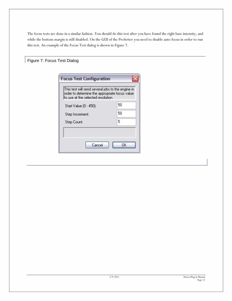
The focus tests are done in a similar fashion. You should do this test after you have found the right base intensity, and while the bottom margin is still disabled. On the GUI of the ProSetter you need to disable auto-focus in order to run this test. An example of the Focus Test dialog is shown in Figure 7.
Figure 7: Focus Test Dialog
3/9/2011 Xitron Plug-in Manual Page 14
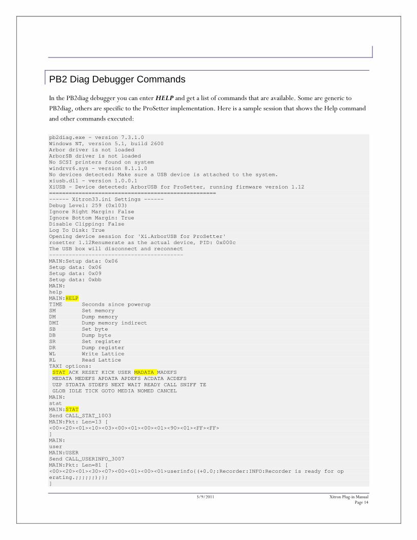
PB2 Diag Debugger Commands In the PB2diag debugger you can enter HELP and get a list of commands that are available. Some are generic to PB2diag, others are specific to the ProSetter implementation. Here is a sample session that shows the Help command and other commands executed:
pb2diag.exe - version 7.3.1.0 Windows NT, version 5.1, build 2600 Arbor driver is not loaded ArborSB driver is not loaded No SCSI printers found on system windrvr6.sys - version 8.1.1.0 No devices detected: Make sure a USB device is attached to the system. xiusb.dll - version 1.0.0.1 XiUSB - Device detected: ArborUSB for ProSetter, running firmware version 1.12 =================================================== ------ Xitron33.ini Settings ------ Debug Level: 259 (0x103) Ignore Right Margin: False Ignore Bottom Margin: True Disable Clipping: False Log To Disk: True Opening device session for 'Xi.ArborUSB for ProSetter' rosetter 1.12Renumerate as the actual device, PID: 0x000c The USB box will disconnect and reconnect ----------------------------------------- MAIN:Setup data: 0x06 Setup data: 0x06 Setup data: 0x09 Setup data: 0xbb MAIN: help MAIN:HELP TIME Seconds since powerup SM Set memory DM Dump memory DMI Dump memory indirect SB Set byte DB Dump byte SR Set register DR Dump register WL Write Lattice RL Read Lattice TAXI options: STAT ACK RESET KICK USER MADATA MADEFS MEDATA MEDEFS APDATA APDEFS ACDATA ACDEFS UZP STDATA STDEFS NEXT WAIT READY CALL SNIFF TE GLOB IDLE TICK GOTO MEDIA NOMED CANCEL MAIN: stat MAIN:STAT Send CALL_STAT_1003 MAIN:Pkt: Len=13 [ <00><20><01><10><03><00><01><00><01><90><01><FF><FF> ] MAIN: user MAIN:USER Send CALL_USERINFO_3007 MAIN:Pkt: Len=81 [ <00><20><01><30><07><00><01><00><01>userinfo{(+0.0;:Recorder:INFO:Recorder is ready for op erating.;;;;;;);}; ]
3/9/2011 Xitron Plug-in Manual Page 15
madata MAIN:MADATA Send CALL_MATDATA_4014 MAIN:Pkt: Len=1017 [ <FF><20><01><40><14><00><01><00><01>+968.0;\n\r+91.0=+0.0;\n\r+92.0=+0.0;\n\r+93.0=+23000. 0;\n\r+1000.0=+1000.0;\n\r+1001.0=Agfa;\n\r+1002.0=+6.0;\n\r+1003.0=+625.0;\n\r+1004.0=+51 0.0;\n\r+1005.0=+200.0;\n\r+1006.0=+999999.0;\n\r+1007.0=+78800.0;\n\r+1008.0=+1.0;\n\r+10 09.0=+1.0;\n\r+1010.0=+0.0;\n\r+1013.0=+0.0;\n\r+1019.0=+1.0;\n\r+1021.0=-25000.0;\n\r+102 2.0=+22000.0;\n\r+1023.0=+578300.0;\n\r+1024.0=+532000.0;\n\r+1025.0=-25000.0;\n\r+1026.0= +22000.0;\n\r+1027.0=+580300.0;\n\r+1028.0=+534000.0;\n\r+1051.0=+75000.0;\n\r+1054.0=+0.0 ;\n\r+1055.0=+1.0;\n\r+1056.0=+4.0;\n\r+1057.0=+0.0;\n\r+1058.0=+0.0;\n\r+1059.0=??;\n\r+1 069.0=+1.0;\n\r+1070.0=+0.0;\n\r+1100.0=+7.5;\n\r+1101.0=+80000.0;\n\r+1102.0=+0.0;\n\r+11 22.0=+433.0;\n\r+1150.0=+7.94;\n\r+1151.0=+250.0;\n\r+1152.0=+0.0;\n\r+1172.0=+450.0;\n\r+ 1200.0=+10.0;\n\r+1201.0=+17200.0;\n\r+1202.0=+0.0;\n\r+1222.0=+450.0;\n\r+1250.0=+10.5833
Issuing the status command, STAT can help you determine that the Xitron interface and the ProSetter are communicating. The material data command, MADATA can be used to dump out the materials that are defined in the database on the ProSetter. This is the same list that the plug-in retrieves when the corresponding menu command is executed. The first media starts at 1000; the second is at 2000, etc.
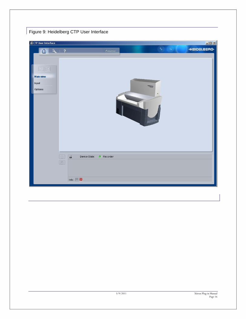
ProSetter Utilities While the Navigator RIP serves as the rendering engine driving the ProSetter, many of the traditional control functions will still reside within the ProSetter CTP User interface, which typically arrives with the ProSetter. This application, an example of which is shown in Figures 8 and 9, must be up and running before starting the Navigator RIP. It communicates with the ProSetter through a simple serial connection.
Figure 8: Heidelberg CTP User Interface
3/9/2011 Xitron Plug-in Manual Page 16
Figure 9: Heidelberg CTP User Interface