heinz tschaetsch metal forming...
TRANSCRIPT

Heinz Tschaetsch
Metal Forming Practise

Heinz Tschaetsch
Metal FormingPractiseProcesses – Machines – Tools
Translated by Anne Koth
123

Author:
Professor Dr.-Ing. e. h. Heinz TschaetschPaul-Gerhardt-Str. 2501309 Dresden, Germany
andKaiserplatz 2a83435 Bad Reichenhall, Germany
Translator:
Anne KothAllsprach-ÜbersetzungsbüroWilthener Str. 6a01324 Dresden, Germany
Originally German edition published by Vieweg Verlag, Wiesbaden 2005
Library of Congress Control Number: 2006926219
ISBN-10 3-540-33216-2 Springer Berlin Heidelberg New YorkISBN-13 978-3-540-33216-9 Springer Berlin Heidelberg New York
This work is subject to copyright. All rights are reserved, whether the whole or part of the material is concerned,specifically the rights of translation, reprinting, reuse of illustrations, recitation, broadcasting, reproduction onmicrofilm or in any other way, and storage in data banks. Duplication of this publication or parts thereof ispermitted only under the provisions of the German Copyright Law of September 9, 1965, in its current version,and permission for use must always be obtained from Springer. Violations are liable for prosecution under theGerman Copyright Law.
Springer is a part of Springer Science+Business Media
springer.com
© Springer-Verlag Berlin Heidelberg 2006Printed in Germany
The use of general descriptive names, registered names, trademarks, etc. in this publication does not imply, even inthe absence of a specific statement, that such names are exempt from the relevant protective laws and regulationsand therefore free for general use.
Cover design: Erich Kirchner, HeidelbergProduction: LE-TEX Jelonek, Schmidt & Vöckler GbR, Leipzig
Printed on acid-free paper 62/3100/YL - 5 4 3 2 1 0

Preface
The book “Metal Forming”, a translation of the eighth revised edition of “Umformtechnik” in German, describes the latest technology in the sector of metal forming. Part I covers metal forming and shearing processes. It describes the main features of these processes, the tooling required and fields of application. Practical examples show how to cal-culate the forces involved in forming and the strain energy. Part II describes forming machines and shows how to calculate their parameters. This section also introduces flexible manufacturing systems in metal forming and the handling systems required for automation (automatic tool changing and workpiece conveyor systems). Part III includes tables and flow diagrams with figures needed to calculate forming forces and strain energy. These production units are automated as much as possible using modern CNC engineering to reduce non-productive time and changeover time, and thus also manufacturing costs. Along-side these economic advantages, however, another important reason for using metal working processes is their technical advantages, such as:
material savings optimal grain direction work hardening with cold forming.
This book runs through all the main metal forming and shearing processes and the tooling and machines they involve. Incremental sheet forming was recently added in Chapter 15.4.
For engineers on the shop floor, this book is intended as an easily-navigable reference work. Students can use this book for reference, saving them time making notes in the lecture theatre so that they can pay better attention to the lecture.
I would particularly like to thank my colleague, Prof. Jochen Dietrich, Ph.D.eng. h.c., lecturer in production processes and CNC engineering at Dresden University of Applied Sciences, Germany (Hochschule für Technik und Wirtschaft), for his involvement as co-author from the 6th edition.
Thanks also to Dr. Mauerman of the Fraunhofer Institute for Machine Tools and Forming Technology, Chemnitz, Germany (Institut für Werkzeugmaschinen und Umformtechink), for his collaboration on the 7th edition of the book.
Bad Reichenhall and Dresden, November 2005 Heinz Tschätsch
Contents
Preface ................................................................................................................................ V
Terms, symbols and units ................................................................................................. 1
Part I Metal forming and shearing processes ................................................................. 3
1 Types of production processes .............................................................................. 5
2 Terms and parameters of metal forming ............................................................. 72.1 Plastic (permanent) deformation ............................................................................... 7 2.2 Flow stress ................................................................................................................ 82.3 Deformation resistance.............................................................................................. 102.4 Deformability ............................................................................................................ 112.5 Degree of deformation and principal strain .............................................................. 11 2.6 Strain rate .................................................................................................................. 14 2.7 Exercise..................................................................................................................... 14
3 Surface treatment ................................................................................................... 153.1 Cold bulk forming..................................................................................................... 15 3.2 Cold sheet forming.................................................................................................... 16 3.3 Hot forming............................................................................................................... 173.4 Exercise..................................................................................................................... 17
4 Upset forging .......................................................................................................... 184.1 Definition .................................................................................................................. 18 4.2 Application................................................................................................................ 18 4.3 Starting stock ............................................................................................................ 184.4 Permissible deformations .......................................................................................... 19 4.5 Upsetting force.......................................................................................................... 234.6 Upsetting work.......................................................................................................... 234.7 Upsetting tooling....................................................................................................... 244.8 Achievable precision................................................................................................. 26 4.9 Defects in upset forging ............................................................................................ 27 4.10 Example calculations ................................................................................................ 27 4.11 Exercise..................................................................................................................... 32
5 Extrusion ................................................................................................................. 33 5.1 Definition .................................................................................................................. 33 5.2 Application of the process......................................................................................... 33 5.3 Types of extrusion process........................................................................................ 34 5.4 Starting stock ............................................................................................................ 355.5 Principal strain .......................................................................................................... 355.6 Calculation of force and mechanical work................................................................ 36 5.7 Extrusion tooling....................................................................................................... 385.8 Reinforcement calculation for single-reinforced dies.................................................... 39 5.9 Achievable precision ................................................................................................ 42 5.10 Defects during extrusion .......................................................................................... 43

VIII Contents
5.11 Sequence of operations diagram .............................................................................. 43 5.12 Example calculations ................................................................................................ 44 5.13 Shape classification .................................................................................................. 495.14 Exercise ..................................................................................................................... 55
6 Thread and gear rolling ......................................................................................... 56 6.1 Types of process ....................................................................................................... 566.2 Application of the processes .................................................................................... 58 6.3 Advantages of thread rolling .................................................................................... 59 6.4 Establishing the initial diameter ............................................................................... 60 6.5 Rolling speeds with cylindrical dies ......................................................................... 61 6.6 Rolling dies .............................................................................................................. 61 6.7 Example..................................................................................................................... 63 6.8 Thread rolling machines ........................................................................................... 64 6.9 Exercise ..................................................................................................................... 68 6.10 Processes and machines for rolling gears ................................................................. 69
7 Cold hubbing .......................................................................................................... 77 7.1 Definition ................................................................................................................. 77 7.2 Application of the process ........................................................................................ 77 7.3 Permissible deformations ......................................................................................... 78 7.4 Calculation of force and mechanical work ............................................................... 78 7.5 Materials which can be hubbed ................................................................................ 79 7.6 Hubbing speed .......................................................................................................... 807.7 Lubrication during hubbing ...................................................................................... 80 7.8 Characteristics of the workpieces to be hubbed ....................................................... 80 7.9 Hubbing tooling ....................................................................................................... 81 7.10 Advantages of cold hubbing ..................................................................................... 82 7.11 Defects during cold hubbing .................................................................................... 83 7.12 Machines for cold hubbing ....................................................................................... 83 7.13 Example calculations ................................................................................................ 84 7.14 Exercise ..................................................................................................................... 85
8 Coining (stamping) ................................................................................................. 86 8.1 Definition ................................................................................................................. 86 8.2 Types and applications of coining processes ........................................................... 86 8.3 Calculation of force and mechanical work ............................................................... 87 8.4 Tooling ..................................................................................................................... 88 8.5 Defects during coining ............................................................................................. 89 8.6 Example .................................................................................................................... 89 8.7 Exercise .................................................................................................................... 90
9 Ironing (wall ironing) ............................................................................................. 91 9.1 Definition ................................................................................................................. 91 9.2 Application of the process ........................................................................................ 91 9.3 Starting stock ............................................................................................................ 91 9.4 Principal strain ......................................................................................................... 919.5 Calculation of force and mechanical work ............................................................... 93 9.6 Example .................................................................................................................... 93 9.7 Exercise ..................................................................................................................... 94

Contents IX
10 Wire drawing .......................................................................................................... 95 10.1 Definition ................................................................................................................. 95 10.2 Application ............................................................................................................... 95 10.3 Starting stock ........................................................................................................... 96 10.4 Principal strain ......................................................................................................... 96 10.5 Permissible deformations ......................................................................................... 96 10.6 Drawing force .......................................................................................................... 9710.7 Drawing speeds ........................................................................................................ 9710.8 Drive power ............................................................................................................. 9910.9 Drawing tooling ....................................................................................................... 10010.10 Example ................................................................................................................... 102 10.11 Exercise..................................................................................................................... 104
11 Tube drawing .......................................................................................................... 105 11.1 Definition ................................................................................................................. 105 11.2 Tube drawing processes ........................................................................................... 105 11.3 Principal strain and drawing force ........................................................................... 106 11.4 Drawing tooling ....................................................................................................... 10711.5 Example ................................................................................................................... 108 11.6 Exercise..................................................................................................................... 108
12 Extrusion ................................................................................................................. 109 12.1 Definition ................................................................................................................. 109 12.2 Application ............................................................................................................... 109 12.3 Starting stock ........................................................................................................... 110 12.4 The extrusion process ............................................................................................... 110 12.5 Principal strain ......................................................................................................... 113 12.6 Strain rates during extrusion .................................................................................... 113 12.7 Extrusion force ......................................................................................................... 11412.8 Mechanical work ...................................................................................................... 11612.9 Tooling ..................................................................................................................... 118 12.10 Extrusion presses ..................................................................................................... 12012.11 Example ................................................................................................................... 121 12.12 Exercise..................................................................................................................... 122
13 Impression-die forging (closed-die forging) ......................................................... 123 13.1 Definition ................................................................................................................. 123 13.2 Starting stock ........................................................................................................... 123 13.3 Types and application of the process ....................................................................... 124 13.4 Processes in the forging die ..................................................................................... 126 13.5 Calculation of force and mechanical work ............................................................... 127 13.6 Tooling ..................................................................................................................... 132 13.7 Design of impression-die forgings ........................................................................... 136 13.8 Achievable precision ................................................................................................ 137 13.9 Example ................................................................................................................... 137 13.10 Exercise..................................................................................................................... 139
14 Deep drawing .......................................................................................................... 141 14.1 Definition ................................................................................................................. 141 14.2 Application of the process ........................................................................................ 141

X Contents
14.3 Forming process and stress distribution ................................................................... 142 14.4 Starting stock ............................................................................................................ 143 14.5 Permissible deformation ........................................................................................... 150 14.6 Deep drawing steps .................................................................................................. 152 14.7 Calculating the drawing force .................................................................................. 154 14.8 Blank holder force .................................................................................................... 15514.9 Drawing work .......................................................................................................... 15614.10 Drawing tooling ....................................................................................................... 15814.11 Achievable precision ................................................................................................ 16614.12 Defects during deep drawing ................................................................................... 167 14.13 Example .................................................................................................................... 169 14.14 Hydromechanical deep drawing ............................................................................... 172 14.15 Sheet hydroforming .................................................................................................. 17414.16 Tube hydroforming .................................................................................................. 179 14.17 Exercise ..................................................................................................................... 184
15 Deep drawing without a blank holder; metal spinning ....................................... 185 15.1 Deep drawing without a blank holder ...................................................................... 185 15.2 Metal spinning .......................................................................................................... 18615.3 Exercise ..................................................................................................................... 192 15.4 Incremental sheet forming ........................................................................................ 193
16 Bending ................................................................................................................... 194 16.1 Definition ................................................................................................................. 194 16.2 Application of the process ........................................................................................ 194 16.3 The bending process ................................................................................................. 194 16.4 Limits of bending deformation ................................................................................. 195 16.5 Spring-back .............................................................................................................. 197 16.6 Determining the blank length ................................................................................... 198 16.7 Bending force ........................................................................................................... 19916.8 Bending work ........................................................................................................... 20116.9 Bending tooling ........................................................................................................ 20316.10 Bending defects ........................................................................................................ 20416.11 Example .................................................................................................................... 204 16.12 Bending machines .................................................................................................... 20516.13 Exercise ..................................................................................................................... 211
17 Embossing ............................................................................................................... 212 17.1 Definition ................................................................................................................. 212 17.2 Application of the process ........................................................................................ 212 17.3 Calculation of force and mechanical work ............................................................... 213 17.4 Embossing tooling .................................................................................................... 21617.5 Embossing defects .................................................................................................... 21717.6 Example .................................................................................................................... 217 17.7 Exercise ..................................................................................................................... 217
18 Shearing .................................................................................................................. 218 18.1 Definition ................................................................................................................. 218 18.2 Shearing process flow .............................................................................................. 218 18.3 Types of shearing process ........................................................................................ 219

Contents XI
18.4 Permissible deformation ........................................................................................... 220 18.5 Calculation of force and mechanical work ............................................................... 220 18.6 Resultant line of action ............................................................................................ 222 18.7 Break clearance ........................................................................................................ 22518.8 Web and rim thickness ............................................................................................. 227 18.9 Achievable precision ................................................................................................ 228 18.10 Shearing tooling ....................................................................................................... 22918.11 Example ................................................................................................................... 238 18.12 Exercise..................................................................................................................... 240
19 Fine blanking (precision blanking) ....................................................................... 241 19.1 Definition ................................................................................................................. 241 19.2 Fields of application ................................................................................................. 24119.3 Shearing process flow .............................................................................................. 241 19.4 Fine blanking tooling design .................................................................................... 242 19.5 Break clearance ........................................................................................................ 24219.6 Forces during fine blanking ..................................................................................... 243 19.7 Fine blanking presses ............................................................................................... 244 19.8 Exercise..................................................................................................................... 246 19.9 Laser cutters ............................................................................................................. 247
20 Joining by forming ................................................................................................. 249 20.1 Clinching .................................................................................................................. 250 20.2 Punch riveting .......................................................................................................... 25420.3 Self-piercing riveting with semi-tubular rivets ........................................................ 257
Part II Presses
21 Types of press ......................................................................................................... 262 21.1 Presses controlled by work ...................................................................................... 262 21.2 Presses controlled by the ram path ........................................................................... 262 21.3 Presses controlled by force ...................................................................................... 263 21.4 Exercise..................................................................................................................... 263
22 Hammers ................................................................................................................. 264 22.1 Columns and frames ................................................................................................. 264 22.2 Types of hammer ..................................................................................................... 264 22.3 Constructional design and calculation of impact energy .......................................... 266 22.4 Fields of application for hammers ............................................................................ 273 22.5 Example ................................................................................................................... 274 22.6 Exercise..................................................................................................................... 274
23 Screw presses .......................................................................................................... 275 23.1 Forms of structural design ........................................................................................ 275 23.2 Functions of the individual styles of construction ................................................... 276 23.3 Calculating the parameters for screw presses .......................................................... 287 23.4 Advantages of screw presses ............................................................................................ 29123.5 Typical fields of application of screw presses ......................................................... 291 23.6 Examples .................................................................................................................. 292 23.7 Exercise..................................................................................................................... 294
XII Contents
24 Eccentric and crank presses .................................................................................. 295 24.1 Types of these presses .............................................................................................. 295 24.2 Press frame materials ............................................................................................... 298 24.3 Frame deflection and deflection energy ................................................................... 299 24.4 Eccentric and crank press drives .............................................................................. 300 24.5 Calculating the parameters ....................................................................................... 306 24.6 Example .................................................................................................................... 310 24.7 Application of eccentric and crank presses .............................................................. 312 24.8 Exercise ..................................................................................................................... 312
25 Knuckle-joint and toggle presses .......................................................................... 313 25.1 Single-point knuckle-joint presses ........................................................................... 313 25.2 Toggle presses – modified knuckle-joint presses ..................................................... 314 25.3 Horizontal knuckle-joint and toggle presses ............................................................ 317 25.4 Exercise ..................................................................................................................... 317
26 Hydraulic presses ................................................................................................... 318 26.1 Hydraulic press drives .............................................................................................. 318 26.2 Example..................................................................................................................... 320 26.3 Advantages of hydraulic presses .............................................................................. 321 26.4 Practical application of hydraulic presses ................................................................ 321 26.5 Exercise ..................................................................................................................... 324
27 Special-purpose presses ......................................................................................... 325 27.1 Deep drawing transfer presses ................................................................................. 325 27.2 Transfer presses for bulk forming ............................................................................ 331 27.3 Automatic punching presses ..................................................................................... 339 27.4 Exercise ..................................................................................................................... 344
28 Workpiece and stock feed systems ........................................................................ 345 28.1 Feed devices for piercing or blanking operations .................................................... 345 28.2 Transport devices in deep drawing transfer presses ................................................. 346 28.3 Transport devices for transfer presses for bulk forming .......................................... 347 28.4 Feed devices to supply round blanks ........................................................................ 348 28.5 Feed devices to convey single workpieces in steps .................................................. 348 28.6 Feed devices to supply forging presses .................................................................... 349 28.7 Exercise ..................................................................................................................... 349
29 Future developments in metal forming presses and tool changing systems ...... 351 29.1 Flexible manufacturing systems ............................................................................... 351 29.2 Automatic tool change systems ................................................................................ 362
Part III Tables ................................................................................................................... 367
Bibliography ....................................................................................................................... 401
Index ................................................................................................................................... 403
Terms, symbols and units
Term Symbol Unit (selection)
Work, mechanical W Nm
Force (force of pressure) F N
Drawing force Fdr N
Blank holder force FBH N
Velocity m/s, m/min
Strain rate s–1
Pressure p Pa, bar
Shear stress N/mm2
Tensile stress R, N/mm2
Tensile strength Rm N/mm2
Yield strength Re N/mm2
Elastic limit RP0.2 N/mm2
Elongation m/m, %
Flow stress kstr N/mm2
Flow stress before forming (cold forming) kstr0 N/mm2
Flow stress after forming (cold forming) kstr1 N/mm2
Resistance to flow pfl N/mm2
Deformation resistance kr N/mm2
Modulus of elasticity E N/mm2
Density t/m3, kg/dm3, g/cm3
Blank length before forming h0, l0 m, mm
Blank length after forming h1, l1 m, mm
Area A m2, mm2
Area before forming A0 m2, mm2
Area after forming A1 m2, mm2
Volume V m3, mm3
Forming temperature T K, ºC
Coefficient of friction –
Efficiency –

2 Terms, symbols and units
Term Symbol Unit (selection)
Deformation efficiency F –
Impact effect (with hammers) i –
Power P Nm/s, W
Acceleration a, g m/s2
Press strokes per minute n min–1, s–1
Stroke length H, h m, mm
Mass moment of inertia Id, kgm2
Mass m kg
Angular velocity s–1
Moment M Nm, J
Tangential force (with crank presses) Tp N
Crank angle (with crank presses) º

3
Part I: Metal forming and shearing processes

1 Types of manufacturing process
The manufacturing processes are subdivided into six main groups.
Fig 1.1 Types of production process
Of these six main groups, this book will study metal forming processes (Fig 1.2) and shearing processes (Fig. 1.3). Metal forming is producing parts by plastic modification of the shape of a solid body. During this process, both mass and material cohesion are maintained.

6 1 Types of manufacturing process
Shearing is separating adjacent parts of a workpiece, or shearing apart whole workpieceswithout creating chips. With the separation processes, a difference is made between shearing and wedge-action cutting according to the form of the blade. In industry, shearing is of greater importance (Fig. 1.4).
Main group 3
Shearing without the creation of chips
Shearing
Shearing off
Blanking
Fig. 1.4 (top) Cutting. a) Wedge-action cutting, b) Shearing
Lancing
Notching
Notching and trimming
Piercing Fig. 1.3 (left) Types of shearing method

2 Terms and parameters of metal forming
2.1 Plastic (permanent) deformation Unlike elastic deformation, during which, for example, a rod under a tensile load returns to its initial length as long as a defined value (elastic limit of the material, Rp0,2 limit) is not ex-ceeded, a workpiece which is plastically deformed retains its shape permanently.
For the elastic range, the following applies:
Z
0 1
0 0
E
l l ll l
Fig. 2.1 Tension test bar – change in length under stress
z in N/mm2 tensile stress in – elongation
l0 in mm initial length l1 in mm length under the influence of force
l in mm lengthening Rm in N/mm2 tensile strength (was B)Re in N/mm2 resistance at the yield point (was S)E in N/mm2 modulus of elasticity.
In the plastic range,a permanent deformation is caused by sufficiently high shear stresses. This makes the atoms in row A1 (Fig. 2.2) change their state of equilibrium in relation to row A2. The extent of the dis-placement is proportional to the extent of the shear stress .
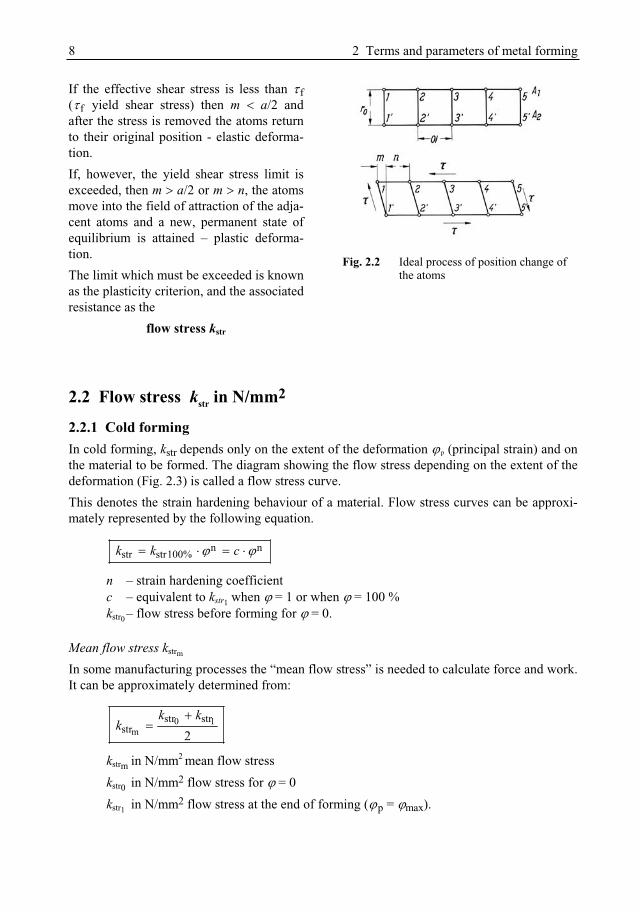
8 2 Terms and parameters of metal forming
If the effective shear stress is less than f( f yield shear stress) then m a/2 and after the stress is removed the atoms return to their original position - elastic deforma-tion. If, however, the yield shear stress limit is exceeded, then m a/2 or m n, the atoms move into the field of attraction of the adja-cent atoms and a new, permanent state of equilibrium is attained – plastic deforma-tion. The limit which must be exceeded is known as the plasticity criterion, and the associated resistance as the
flow stress kstr
Fig. 2.2 Ideal process of position change of the atoms
2.2 Flow stress kstr in N/mm2
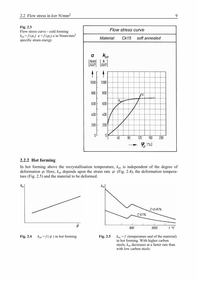
2.2.1 Cold forming In cold forming, kstr depends only on the extent of the deformation p (principal strain) and on the material to be formed. The diagram showing the flow stress depending on the extent of the deformation (Fig. 2.3) is called a flow stress curve. This denotes the strain hardening behaviour of a material. Flow stress curves can be approxi-mately represented by the following equation.
n nstr str100%k k c
n – strain hardening coefficient c – equivalent to kstr1 when = 1 or when = 100 % kstr0 – flow stress before forming for = 0.
Mean flow stress kstrm
In some manufacturing processes the “mean flow stress” is needed to calculate force and work. It can be approximately determined from:
0 1m
str strstr 2
k kk
kstrm in N/mm2 mean flow stress kstr0 in N/mm2 flow stress for = 0 kstr1 in N/mm2 flow stress at the end of forming ( p = max).
2.2 Flow stress in kstr N/mm2 9
Fig. 2.3 Flow stress curve - cold forming kstr = f ( p) a = f ( p) a in Nmm/mm3
specific strain energy
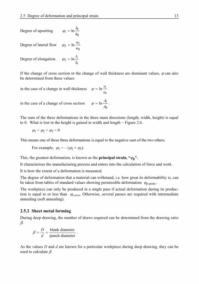
2.2.2 Hot forming In hot forming above the recrystallisation temperature, kstr is independent of the degree of deformation . Here, kstr depends upon the strain rate (Fig. 2.4), the deformation tempera-ture (Fig. 2.5) and the material to be deformed.
Fig. 2.4 kstr = f ( ) in hot forming Fig. 2.5 kstr = f (temperature and of the material) in hot forming. With higher carbon steels, kstr decreases at a faster rate than with low carbon steels.

10 2 Terms and parameters of metal forming
At high strain rates kstr rises during hot forming since the cohesion-reducing processes which arise due to recrystallisation no longer take place completely.
2.2.3 Calculation of the flow stress kstrsh for semi-hot forming
shn mstr pk c 1400
3Tc
kstrsh in N/mm2 flow stress in semi-hot forming T in °C temperature in semi-hot forming c in N/mm2 empirical calculation coefficient
p – principal strain n – exponent of p
in s–1 strain rate m – exponent of
Table 2.1 Exponents and semi-hot forming temperatures
Material n m T °C CC 15 0.1 0.08 500 300C 22 0.09 0.09 500 300C 35 0.08 0.10 550 283C 45 0.07 0.11 550 283C 60 0.06 0.12 600 267X 10 Cr 13 0.05 0.13 600 267
Example: where: material C 60 operating temperature: T = 600 °C principal strain: p = 1.10 = 110 % strain rate = 250 s–1
solution: c = 267, n = 0.06, m = 0.12 from Table 2.1
kstrsh = n mpc = 267 · 1.10.06 · 2500.12
kstrsh = 267 · 1.0 · 1.94 = 2515 N/mm
2.3 Deformation resistance kr
The resistance to be overcome during a deformation is composed of the flow stress and the friction resistances in the tool, which are brought together under the term “resistance to flow”.

2.4 Deformability 11
frr strk k p
kr in N/mm2 deformation resistance kstr in N/mm2 flow stress pfl in N/mm2 resistance to flow
The resistance to flow pfl can be calculated mathematically for rotationally symmetric pieces.
11
fl str1
13
dp kh
From this it follows that for the deformation resistance kw
11
r str1
113
dk kh
kstrl in N/mm2 flow stress at the end of forming d0 in mm diameter before forming h0 in mm height before forming (Fig. 4.6)
– coefficient of friction ( = 0.15) d1 in mm diameter after forming h1 in mm height after forming
F – deformation efficiency.
For asymmetric pieces, which can only be studied mathematically to a limited extent, the de-formation resistance is determined with the help of the deformation efficiency.
1strr
F.
kk
2.4 Deformability This means the ability of a material to be deformed. It depends upon:
2.4.1 Chemical composition In steels, for example, the cold deformability depends on the C content, the components of the alloy (Ni, Cr, Va, Mo, Mn) and the phosphor content. The higher the C content, the P content and the alloy components, the lower the deformability is.
2.4.2 Crystalline structure Here, the grain size and above all the pearlite structure are important. – Grain size Steels should be as fine-grained as possible, since in steels with small to medium grain size, the crystallites are easier to displace on the crystallite slip planes.

12 2 Terms and parameters of metal forming
– Pearlite structure Pearlite is the carbon carrier in the steel. It is difficult to deform. For this reason it is important that the pearlite is equally distributed in the ferritic matrix, which is easy to cold form.
2.4.3 Heat treatment
An equally-distributed structure is achieved by normalising (above Ac3) and fast cooling. The resulting hardness is cancelled out by subsequent soft annealing (around Ac1). Note: only soft annealed material can be cold formed.
2.5 Degree of deformation and principal strain
2.5.1 Bulk forming process
The measure of the extent of a deformation is the degree of deformation. The calculation is generally made from the relation between an indefinitely small measurement difference, dx,and an existing measurement x. By integrating it into the limits x0 to x1 this produces
1
0
1x
0
d ln .x
x
x xx x
when it is presumed that the volume of the body to be deformed remains constant during form-ing.
V = l0 · w0 · h0 = l1 · w1 · h1.
According to which value changes the most during forming, a difference is made (Figure 2.6) between
Figure 2.6 Cuboid before forming with the measurements h0, w0, l0 and after forming with the measure-ments h1, w1, l1
2.5 Degree of deformation and principal strain 13
Degree of upsetting 11
0ln h
h
Degree of lateral flow 12
0ln w
w
Degree of elongation. 13
0ln l
l
If the change of cross section or the change of wall thickness are dominant values, can also be determined from these values:
in the case of a change in wall thickness 1
0ln s
s
in the case of a change of cross section 1
0ln A
A.
The sum of the three deformations in the three main directions (length, width, height) is equal to 0. What is lost in the height is gained in width and length Figure 2.6.
1 + 2 + 3 = 0
This means one of these three deformations is equal to the negative sum of the two others.
For example, 1 = – ( 2 + 3).
This, the greatest deformation, is known as the principal strain, “ p”.It characterises the manufacturing process and enters into the calculation of force and work. It is how the extent of a deformation is measured. The degree of deformation that a material can withstand, i.e. how great its deformability is, can be taken from tables of standard values showing permissible deformation p perm .The workpiece can only be produced in a single pass if actual deformation during its produc-tion is equal to or less than p perm. Otherwise, several passes are required with intermediate annealing (soft annealing).
2.5.2 Sheet metal forming During deep drawing, the number of draws required can be determined from the drawing ratio
.
blank diameterpunch diameter
Dd
.
As the values D and d are known for a particular workpiece during deep drawing, they can be used to calculate
14 2 Terms and parameters of metal forming
Here, tables of standard values (see the chapter on deep drawing) are once more used to find the permissible drawing ratio perm; it is then compared with the calculated drawing ratio. The workpiece can only be produced in a single phase if is equal to or less than perm. Otherwise, several passes are necessary.
2.6 Strain rate If a deformation is carried out in the time t, this results in an average strain rate of:
mwt
wm in %/s mean strain rate in % degree of deformation
t in s deformation time
It may, however, also be determined by the ram / slide velocity and the initial height of the workpiece.
0
vh
in s–1 strain rate v in m/s velocity of the ram / slide h0 in s height of the blank.
2.7 Exercise on Chapter 2 1. Which conditions must be met in order to achieve plastic (permanent) deformation? 2. What is meant by “flow stress” kstr?3. How can the flow stress value be ascertained? 4. How can the mean yield stress be (approximately) calculated? 5. What influence does the forming temperature have on flow stress? 6. What influence does the strain rate have on flow stress?
a) during cold forming b) during hot forming?
7. What is meant by “cold forming”? 8. What is meant by “deformability”? 9. What factors does the deformability of a material depend upon? 10. Explain these terms:
degree of upsetting degree of lateral flow degree of elongation.
11. What is meant by “principal strain”?
3 Surface treatment
If the blanks (sections of wire or rods) were simply inserted into the moulding die and then pressed, the die would be made useless after only a few units. Galling would occur in the die because of cold welding between the workpiece and the die. As a result, burrs would form on the die which would make the pressed parts unusable. For this reason, the blanks must be care-fully prepared before pressing. This preparation, which is summed up as “surface treatment”, includes
pickling, phosphating, lubricating.
3.1 Cold bulk forming
3.1.1 Pickling
The pickling process is intended to remove oxidic coatings (rust, scale) so that the surface of the press blank is metallically clean, ready for the actual surface treatment. Diluted acids are used as a pickling agent, e.g. for steel, 10% sulphuric acid (percent by vol-ume).
3.1.2 Phosphating
If grease, oil or soap were directly applied to a metallically clean (pickled) blank as a lubricant, the lubricant would have no effect. The film of lubricant would come off during pressing and cold welding and galling would take place. Therefore a lubricant carrier coating must be applied first, forming a firm bond with the blank material. Phosphates are used as a carrier coating. Phosphating applies a non-metallic lubricant carrier, firmly bonded with the base material of the blank made of
steel (with the exception of Nirosta steels) zinc and zinc alloys aluminium and aluminium alloys.
This porous layer acts as a lubricant carrier. The lubricant diffuses into the pores and can thus no longer be rubbed off of the blank. Coating thicknesses of the applied phosphates range between 5 and 15 m.
16 3 Surface treatment
3.1.3 Lubrication
– Function of the lubricant:The lubricant is intended to:
– prevent the die and the workpiece from coming into direct contact with one another, in order to make it impossible for material to be transferred from the die to the workpiece (cold welding);
– reduce friction between the surfaces gliding against one another; – keep the heat which occurs during forming within limits.
– Lubricants for cold formingFor cold forming, the following materials can be employed as lubricants.
– Lime (liming)Liming means that the blanks are immersed in a solution of water with 8 percent lime by weight heated to 90°C. Liming can only be used for steel for small deformations.
– SoapHere, for example, solutions of hard soap are used with 4-8 percent soap by weight at 80°C and an immersion time of 2-3 minutes. Their use is appropriate when there is a medium lu-bricant requirement.
– Mineral oils (possibly with a little supplementary grease)These lubricants, available on the market as “Press Oils”, are suited to high lubricant re-quirements, above all in automatic production. As well as lubrication, they also assume a cooling function.
– Molybdenum disulphide (molycote suspensions)For lubricants on a molybdenum disulphide basis, which are suited to the highest lubrica-tion requirements,
MoS2 water suspensions
are mainly used. Immersion time ranges from 2 to 5 minutes at a temperature of 80 °C. The concentration (mean value) is around 1 : 3 (i.e. 1 part molycote, 3 parts water).
For particularly difficult deformations, higher-concentrated suspensions are also used.
3.2 Cold sheet forming As a rule pure lubricating agents such as drawing oils or drawing greases suffice for deep drawing, preventing direct contact between the die and the workpiece.

3.4 Exercise on Chapter 3 17
3.3 Hot forming (drop forging) During drop forging, sawdust and graphite suspensions are used as lubricants and anti-seize agents. Optimal results can be achieved with 4% colloidal graphite in water or light oil. With the liquid lubricants, however, attention must be paid to correct dosage. Too much suspension raises the gas pressure in the die and makes moulding difficult.
3.4 Exercise on Chapter 3 1. What is the function of the lubricant during forming? 2. Why can the blank not simply be lubricated with oil or grease during cold forming? 3. How must the blanks be pre-treated (surface treated) before a cold forming pressing proc-
ess? 4. What lubricants are used in cold forming? 5. What lubricants are used in drop forging?

4 Upset forging
4.1 Definition Upset forging is a bulk forming process where the effect of the pressure is on the longitudinal axis of the workpiece.
4.2 Application Commonly used for the production of mass-produced parts such as screws, rivets, head bolts, valve lifters etc. (Figures 4.1, 4.2 and 4.3).
4.3 Starting stock The starting stock is a length of rod cut from round or shaped stock. In many cases, above all in screw and bolt production, production is carried out from wire coils (Figure 4.2). As rolled stock is cheaper than drawn stock, it is used most commonly.
Figure 4.1 Typical upset parts

4.4 Permissible deformations 19
Figure 4.2 Steps in the production of a bolt on a transfer press with a thread rolling device. 0 shear off stock, 1 pre-form head, 2 finish head, 3 reduce shank to diameter for thread rolling, 4 stamp out hexagon, 5 chamfer shank (round off), 6 thread rolling
Figure 4.3 Production of a valve lifter.1 initial blank 2 pre-form 3 final heading
4.4 Permissible deformations Here, a difference must be made between two criteria:
4.4.1 Measurement for the extent of deformation This sets the limits for the material to be formed (deformability).
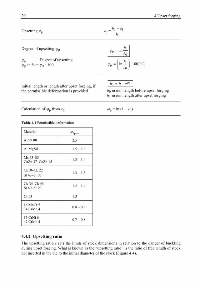
20 4 Upset forging
Upsetting p p = 0 1
0
h hh
Degree of upsetting p
p Degree of upsetting p in % = h · 100
1p
0ln h
h
1p
0ln 100[%]h
h
Initial length or length after upset forging, if the permissible deformation is provided
p0 1h h eh0 in mm length before upset forging h1 in mm length after upset forging
Calculation of p from p p = ln (1 – p)
Table 4.1 Permissible deformation
Material pperm.
Al 99.88 2.5
Al MgSil 1.5 – 2.0
Ms 63–85 CuZn 37–CuZn 15 1.2 – 1.4
Ck10–Ck 22 St 42–St 50 1.3 – 1.5
Ck 35–Ck 45 St 60–St 70 1.2 – 1.4
Cf 53 1.3
16 MnCr 5 34 CrMo 4 0.8 – 0.9
15 CrNi 6 42 CrMo 4 0.7 – 0.8
4.4.2 Upsetting ratio The upsetting ratio s sets the limits of stock dimensions in relation to the danger of buckling during upset forging. What is known as the “upsetting ratio” is the ratio of free length of stock not inserted in the die to the initial diameter of the stock (Figure 4.4).
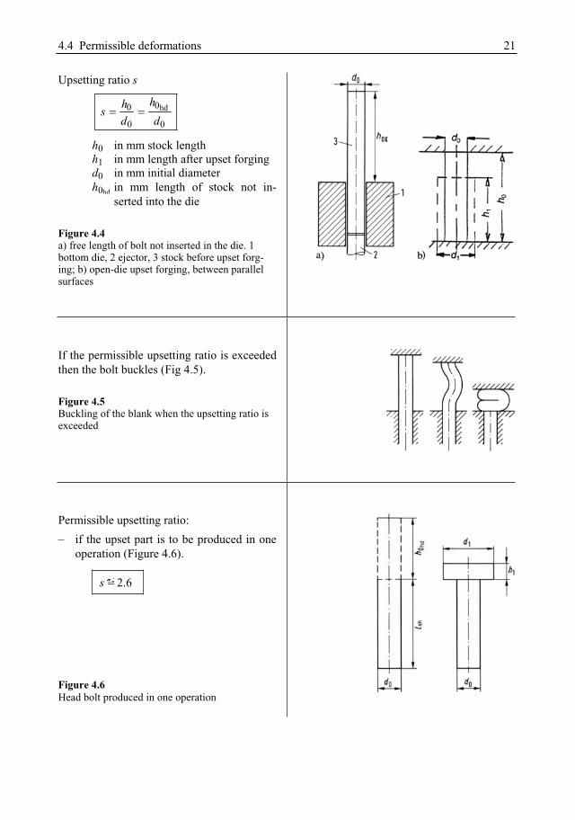
4.4 Permissible deformations 21
Upsetting ratio s
hd00
0 0
hhsd d
h0 in mm stock length h1 in mm length after upset forging d0 in mm initial diameter h0hd in mm length of stock not in-
serted into the die
Figure 4.4 a) free length of bolt not inserted in the die. 1 bottom die, 2 ejector, 3 stock before upset forg-ing; b) open-die upset forging, between parallel surfaces
If the permissible upsetting ratio is exceeded then the bolt buckles (Fig 4.5).
Figure 4.5 Buckling of the blank when the upsetting ratio is exceeded
Permissible upsetting ratio: – if the upset part is to be produced in one
operation (Figure 4.6).
s 2.6
Figure 4.6 Head bolt produced in one operation