helical gear motors bege type g & m - duru … helical gear motors – type g & m general...
TRANSCRIPT

Helical Gear Motors
BEGE Type G & M
Your drive, our (trans)mission
BEGE Power Transmission
Anton Philipsweg 30
2171 KX Sassenheim
The Netherlands
T: +31 252-220 220
W: www.bege.nl

BEGE Helical Gear Motors – Type G & M General information
Power Range 0.09 – 22 kW
Standard design:
Motor : Three phase (IEC) AC – motor
Voltage : 230 / 400V – 50Hz
400 / 690 V – 50Hz
Protection class : IP 55
Insulation class : F
Efficiency : Premium efficiency IE3
(≥ 0,75 kW – 2 / 4 / 6 poles)
Mounting position : B3
B5 *
(*) Additional price

Options Gear Unit
• Stainless steel version (catalogue on request)
• Built-in MIG encoder
• Special shaft diameters
• Stainless steel shafts
• Reinforced output shaft bearings
• Free input shaft
• Special mounting positions
• Special lubricants
• Other colors and/or paint quaility
• Speedi sleeve
BEGE Helical Gear Motors – Type G & M Options
Options Motors
• Increased protection class
• Increased insulation class
• Increased efficiency
• Special voltage / frequency
• Special shaft dimensions
• Forced cooling
• Brake motor
• (Brushless) DC-motor
• Pole-changing motor
• Explosion proof motor ATEX
• 1-phase AC-motor
• Encapsulated terminal box
• Temperature switch (bimetal)
• P.T.C. thermistor
• Rain cover (mounting position V1 / V5)

BEGE Helical Gear Motors – Type G & M Mounting position
Mounting positions
6 basic mounting positions : B3 / B5 to V6 / V3
B3 (Standard)
The correct mounting position is required at the time of ordering: Changing mounting position after delivery normally requires correction of the oil
level and possibly other modifications such as installing sealed bearings
The supplied breather screw should be screwed in place (see
mounting instructions)
Special mounting positions on request

BEGE Helical Gear Motors – Type G & M Terminal box position
Terminal box
4 basic terminal box positions : A – B – C -D
A (Standard)
2 basic cable gland positions : R – L
R (Standard)
The standard terminal box position is “A/R” The motor terminal box can be mounted in different positions according to the
drawing and should be specified when ordering

BEGE Helical Gear Motors – Type G & M Gear motor coating
Gear motor coating
Standard coating : RAL 7031 (blue grey)
Drying time 1K coating: 24 hours
Different colours and coating qualities are available on request
Available coatings: HAMMER SCALE COATING JF GREY
JF ZF COATING RAL 1015
JF ZF COATING RAL 1021
JF ZF COATING RAL 1016
JF ZF COATING RAL 2009
JF ZF COATING RAL 3016
JF ZF COATING RAL 5005
JF ZF COATING RAL 5007
JF ZF COATING RAL 5009
JF ZF COATING RAL 5012
JF ZF COATING RAL 5015
JF ZF COATING RAL 5017
JF ZF COATING RAL 6005
JF ZF COATING RAL 6016
JF ZF COATING RAL 6011
JF ZF COATING RAL 6018
JF ZF COATING RAL 6032
JF ZF COATING RAL 7030
JF ZF COATING RAL 7031 (Standard)
JF ZF COATING RAL 9005
JF ZF COATING RAL 9006
JF ZF COATING RAL 9010

BEGE Helical Gear Motors – Type G & M Gear motor coating
Gear motor coating
Standard coating : RAL 7031 (blue grey)
Drying time 2K coating: 4 hours for same-day delivery
24 hours for next-day delivery
Different colours and coating qualities are available on request
Special coatings:
Available coatings:
Drying time
SHOPPRIMER RAL 7012 2 hours
GK-2K-PLASTIC PRIMER GREY 24 hours
Washprimer 24 hours
JF ZF PRIMER WHITE 24 hours
Kortadur 2K-Epoxyprimer RAL 7031 2 hours
Kortadur 2K-Epoxyprimer RAL 9005 2 hours
2K-COATING BLANK SHINE
2K-COATING RAL 5005 SHINE
2K-COATING RAL 5007 SHINE
2K-COATING RAL 5009 SHINE
2K-COATING RAL 5011 SHINE
2K-COATING RAL 6005 SHINE
2K-COATING RAL 6029 SHINE
2K-COATING RAL 6032 SHINE
2K-COATING RAL 7030 SHINE
2K-COATING RAL 7031 SHINE
2K-COATING RAL 7035 SHINE
2K-COATING RAL 7042 SHINE
2K-COATING RAL 7044 SHINE
2K-COATING RAL 9005 SHINE
2K-COATING RAL 9006 Metallic SHINE
2K-COATING RAL 9010 SHINE

BEGE Helical Gear Motors – Type G & M Lubrication
Lubrication
These lubricants are for ambient
temperatures from -5°C to +40°C The lubricant quantity responds to the mounting
position shown on the name plate and depends on
gear size and mounting position.
Special lubricants: • For extreme low temperatures -40°C to 0°C
• A non toxic lubricant for the food processing
industry, certified to USDA H1 standard
• Further special lubricants on request
Standard lubrication G-series: Mineral lubricant ISO VG220
Standard lubrication M-series: Synthetic lubricant VG460
BEGE Helical Gear Motors – Type G & M 4-stage gear units
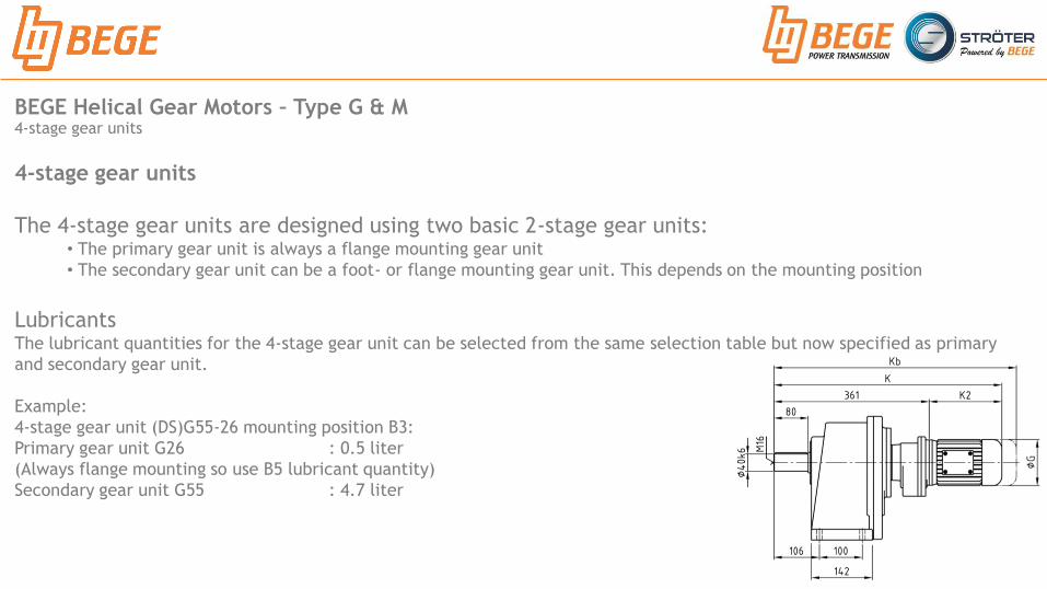
4-stage gear units
The 4-stage gear units are designed using two basic 2-stage gear units: • The primary gear unit is always a flange mounting gear unit
• The secondary gear unit can be a foot- or flange mounting gear unit. This depends on the mounting position
Lubricants The lubricant quantities for the 4-stage gear unit can be selected from the same selection table but now specified as primary
and secondary gear unit.
Example:
4-stage gear unit (DS)G55-26 mounting position B3:
Primary gear unit G26 : 0.5 liter
(Always flange mounting so use B5 lubricant quantity)
Secondary gear unit G55 : 4.7 liter

BEGE Helical Gear Motors – Type G & M Efficiency
Gears selection
The correct choice of gear unit starts by determining the required torque. The gear selection lists specify for the respective output drive speed n2 and the theoretical output torque T2n
The power rating of the motor P1n to be installed can then be chosen (include safety margin)
Helical gear motors have a very high efficiency Generally the efficiency for each gear stage is 0,98 < η > 0,95 and 0,95 < η > 0,90 for a gear stage with oil seals
Our experience shows that;
• The total efficiency for a 2-stage gear is η = 0,90
• The total efficiency for a 3-stage gear is η = 0,86

BEGE Helical Gear Motors – Type G & M Criteria
Gears selection
Criteria We recommend consulting with us regarding the operation in detail if two or more of the following points apply:
• Vertical arrangement (mounting position V5 and V1 or V6 and V3)
• Ratio i < 20 helical gear drive
• Drive speed n1 > 1500 min-1
• High ambient temperature > 40°C
• Specific installation conditions apply e.g. gear enclosure, radiated heat, restricted installation space, etc.

BEGE Helical Gear Motors – Type G & M Load type
Drive design Certain details such as motor power, output speed, output torque etc. Are necessary for configuring the drive.
To match the operating conditions the service factor fb needs to be determined.

BEGE Helical Gear Motors – Type G & M Service factor
Gears selection
Drive design Certain details such as motor power, output
speed, output torque etc. are necessary for
configuring the drive.
To match the operating conditions the
service factor fb needs to be determined.
The service factor has to be multiplied by:
• 1.2 for the application with a combustion
wengine drive, with reversing operation and
winstantaneous overloads
• 1.5 for the application with a brake motor

BEGE Helical Gear Motors – Type G & M Radial load at the output shaft
Gears selection
Drive design The radial load at the output and input shaft which is caused by
transmission elements can be calculated with the following formula:
FR2 = Radial load [N]
Td = Torque of the shaft [Nm]
fz = Transmission element factor
fb = Service factor
dw = Mean diameter of the transmission element [mm]
Changing the rotation direction, the loading
direction, or the use of reinforced bearings, can
result in a higher permissible radial load FR2max

BEGE Helical Gear Motors – Type G & M Axial load at the output shaft
Gears selection
Axial load The permissible axial load is 50% of the permissible radial load FR2max.
(The permissible axial and radial load may be applied simultaneous on the output shaft)
Reinforced bearings If the permissible radial/axial load is not sufficient, it is possible to apply reinforced bearings
for the output shaft at additional cost.
If the axial load is higher then the permissible axial load, please contact BEGE

BEGE Helical Gear Motors – Type G & M Maximum permissible radial load on the output shaft
Gears selection
Maximum permissible radial load The permissible radial load effected on the output shaft is given in Newton [N]
The G-series it depends on the power and speed
The M-series it depends on the gear unit size and speed
n2 : Speed of the output shaft [min-1]
P : Power [kW]

BEGE Helical Gear Motors – Type G Maximum permissible radial load on the input shaft
Gears selection
Maximum permissible radial load The permissible radial load effected on the input shaft is given in Newton [N]
Pay attention to radial force when;
• Transmission by v-belt or chain

BEGE Helical Gear Motors – Type G Gear motor with IEC-adapter
Gears selection
IEC-adapter The gear motors can be delivered with an IEC-adapter.
Thereby any motor can be installed with an IEC standard flange (oil sealed motor required)
Advantage: Install a patented magnetic pulse encoder (MIG), which is implemented as an intermediate flange.
With the combination of IEC gear unit / MIG / 3-Ph motor it’s possible to implement a gear motor for;
• Frequency controlled positioning
• Dosing control
• Torque control
• etc.
The mechanical connection between motor and gear is achieved via a toothed coupling (included)

BEGE Helical Gear Motors – Type G Gear motor with IEC-adapter
Gears selection
IEC-adapter The gear motors can be delivered with an IEC-adapter.
Thereby any motor can be installed with an IEC standard flange.
• Simple installation and dismantling
• No frictional corrosion
• Compact design
• Cost effective spare parts
• By using different bores in the toothed coupling, it’s
kpossible to fit different sized motor frames to each gear
BEGE Helical Gear Motors – Type G & M Motors
Gears selection
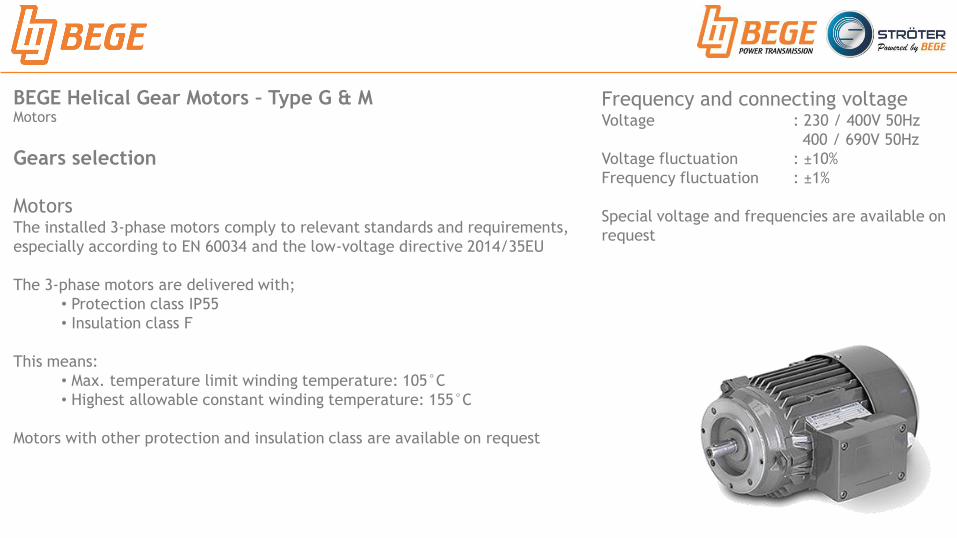
Motors The installed 3-phase motors comply to relevant standards and requirements,
especially according to EN 60034 and the low-voltage directive 2014/35EU
The 3-phase motors are delivered with;
• Protection class IP55
• Insulation class F
This means:
• Max. temperature limit winding temperature: 105°C
• Highest allowable constant winding temperature: 155°C
Motors with other protection and insulation class are available on request
Frequency and connecting voltage Voltage : 230 / 400V 50Hz
400 / 690V 50Hz
Voltage fluctuation : ±10%
Frequency fluctuation : ±1%
Special voltage and frequencies are available on
request
BEGE Helical Gear Motors – Type G & M Energy class IE3
Gears selection
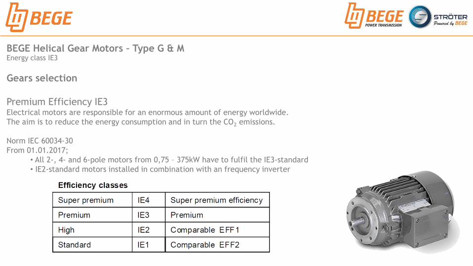
Premium Efficiency IE3 Electrical motors are responsible for an enormous amount of energy worldwide.
The aim is to reduce the energy consumption and in turn the CO2 emissions.
Norm IEC 60034-30
From 01.01.2017;
• All 2-, 4- and 6-pole motors from 0,75 – 375kW have to fulfil the IE3-standard
• IE2-standard motors installed in combination with an frequency inverter

BEGE Helical Gear Motors – Type G & M Rated power output
Gears selection
Continual operation The given ratings of those in the selection table are applicable for continual operation;
• Operating mode S1
• Rated voltage : ±10%
• Frequency : 50Hz ±1%
• Max. ambient temperature : 40°C
• Max. installation height : 1000 m
• Max. humidity : 92%

BEGE Helical Gear Motors – Type G & M Switching operation
Gears selection
The permissible switching operation (permissible frequency
per hour) of a motor is calculated from the switching
frequency specified in the data list:
A : Max. switching operation (with load)
A0 : Max. switching operation (without load)
JM : Motor’s moment of inertia (on request)
JM : Additional moment of inertia (load) maximum
Motors with insulation class F
Max. starting frequency A0

BEGE Helical Gear Motors – Type G & M Operating modes
Gears selection
Operating modes The motor rating is dependent on the type of operation
The standard operating type supplied is S1
Operating mode S1
Operating mode S2
Operating mode S3
Operating mode S4
Operating mode S5
Operating mode S6

BEGE Helical Gear Motors - Type G Solution for high gear ratios
Smooth shaft Pinion shaft
Smooth shaft | Pinion shaft
The advantage of pinion shafts are;
• Higher gear ratios
• Shortened installation length
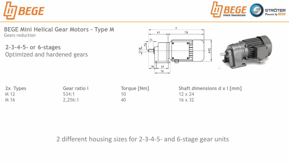
BEGE Mini Helical Gear Motors – Type M Gears reduction
2-3-4-5- or 6-stages
Optimized and hardened gears
2x Types Gear ratio i Torque [Nm] Shaft dimensions d x l [mm]
M 12 534:1 10 12 x 24
M 16 2,256:1 40 16 x 32
2 different housing sizes for 2-3-4-5- and 6-stage gear units

BEGE Mini Helical Gear Motors – Type M Gears reduction
2-3-4-5- or 6-stages
Optimized and hardened gears
M12 Foot mounted
M12 F Flange mounted

BEGE Helical Gear Motors – Type G Gears reduction
2 - stages
Hardened and grinded gears
8x Types Gear ratio i Torque [Nm] Shaft dimensions d x l [mm]
G 00 56:1 35 18 x 36
G 11 55:1 70 20 x 40
G 22 55:1 175 25 x 50
G 26 55:1 420 35 x 70
G 33 55:1 630 40 x 80
G 44 55:1 1400 50 x 100
G 55 48:1 1960 65 x 130
G 66 47:1 2590 75 x 150

BEGE Helical Gear Motors – Type G Gears reduction
G00 Foot mounted
G00 F Flange mounted
2 - stages
Hardened and grinded gears

BEGE Helical Gear Motors – Type G Gears reduction
3 - stages
Hardened and grinded gears
6x Types Gear ratio i Torque [Nm] Shaft dimensions d x l [mm]
G 110 438:1 70 20 x 40
G 220 431:1 175 25 x 50
G 260 431:1 420 35 x 70
G 330 431:1 630 40 x 80
G 440 431:1 1,400 50 x 100
G 550 257:1 1,960 65 x 135

BEGE Helical Gear Motors – Type G Gears reduction
G110 Foot mounted
G110 F Flange mounted
3 - stages
Hardened and grinded gears

BEGE Helical Gear Motors – Type G Gears reduction
4 - stages
Hardened and grinded gears
9x Types Gear ratio i Torque [Nm] Shaft dimensions d x l [mm]
G 26-00 2,685:1 420 35 x 70
G 33-00 2,685:1 630 40 x 80
G 44-11 2,641:1 1,400 50 x 100
G 44-22 2,641:1 1,400 50 x 100
G 55-22 2,651:1 1,960 65 x 130
G 55-26 2,651:1 1,960 65 x 130
G 55-33 2,651:1 1,960 65 x 130
G 66-22 2,625:1 2,590 75 x 150
G 66-26 2,625:1 2,590 75 x 150
G 66-33 2,625:1 2,590 75 x 150

BEGE Helical Gear Motors – Type G Gears reduction
G26-00 Foot mounted
G26-00 F Flange mounted
4 - stages
Hardened and grinded gears
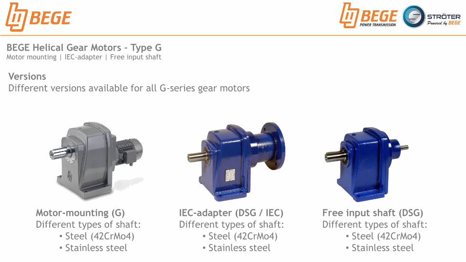
BEGE Helical Gear Motors – Type G Motor mounting | IEC-adapter | Free input shaft
Versions
Different versions available for all G-series gear motors
Free input shaft (DSG)
Different types of shaft:
• Steel (42CrMo4)
• Stainless steel
IEC-adapter (DSG / IEC)
Different types of shaft:
• Steel (42CrMo4)
• Stainless steel
Motor-mounting (G)
Different types of shaft:
• Steel (42CrMo4)
• Stainless steel

BEGE Helical Gear Motors Modular system
- BEGE Type G
Modular systems
Mounting to different gear motors possible (e.g. BEGE, STRÖTER, etc.)
• BEGE G-series with other G-series
• BEGE G-series with STRÖTER K-series
• BEGE G-series with STRÖTER AM-series
• BEGE G-series with STRÖTER AM/M-series
• BEGE G-series with Worm Gear Motors
• Etc.

BEGE Helical Gear Motors – Type G & M Information for ordering

BEGE Helical Gear Motors – Type G Applications: Lifting

BEGE Helical Gear Motors – Type G ATEX Certificate

Specifications
Ratio 6,0:1 to 2256:1 (2-3-4-5- and 6-stage)
Torque 3,9 to 40 Nm
Power 0,09 kW
Shaft diameter 12 to 16 mm
IEC size 56
# Frame size 2
Material Cast iron housing
Executions Foot- or flanged-mounted
k High efficiency
k Optimized and hardened gears
k Modular system
BEGE Mini Helical Gear Motors – Type M Specifications

BEGE Helical Gear Motors – Type G Specifications
Specifications
Ratio 3,7:1 to 2.685:1 (2-3- and 4-stage)
Torque 35 to 2.590 Nm
Power 0,09 to 22 kW
Shaft diameter 18 to 75 mm
IEC size 56 to 180
# Frame size 8
Material Cast iron housing
Executions Motor-mounting, IEC-adapter, Free input shaft, Foot- or flange-mounting
k High efficiency
k Hardened & grinded gears
k Modular system

Your drive, our (trans)mission
BEGE Power Transmission
Anton Philipsweg 30
2171 KX Sassenheim
The Netherlands
T: +31 252-220 220
W: www.bege.nl