helicopter rotor blade radar antenna helicopter rotor blade radar antenna i unclassified) ... a long...
TRANSCRIPT

HELICOPTER ROTOR BLADE RADAR ANTENNA I UNCLASSIFIED)
l>»
O
REPORT NO. 299-099-285
HELICORTER COMPANY
FORT WORTH . TEXAS DIVISION OF BILL ACROtPACC CORPORATION • A MnMI COMPANY
\)U^T^-cl>JT*-0^ l^ ^^«»^«H« l-^TÄ
HllTHBUOOPTBR ooMmMv • awfOH f Mil MaotMct «gwewiio«
HELICOPTER ROTOR BLADE RADAR ANTENNA
Report No. 299-099-285
H. W. Upton Bell Helicopter Company
Fort Worth, Texas
D. W. Young David W. Young and Associates, Inc.
Canoga Park, California
Presented to the University of Michigan 11th Annual Radar Symposium held at Fort Monmouth, N. J., July 8 - 10, 1965
Most of the work reported herein was performed under the Joint Array Navy Aircraft Instrumentation Research Program (JANAIR), Contract Number Nonr 4148(00).-
"ti v^rß.l'fcüT-(ör\ IS C^<- IKWIT £f£
j

HELICOPTER ROTOR BUDE RADAR A MT EN NA
1. INTRODUCTION
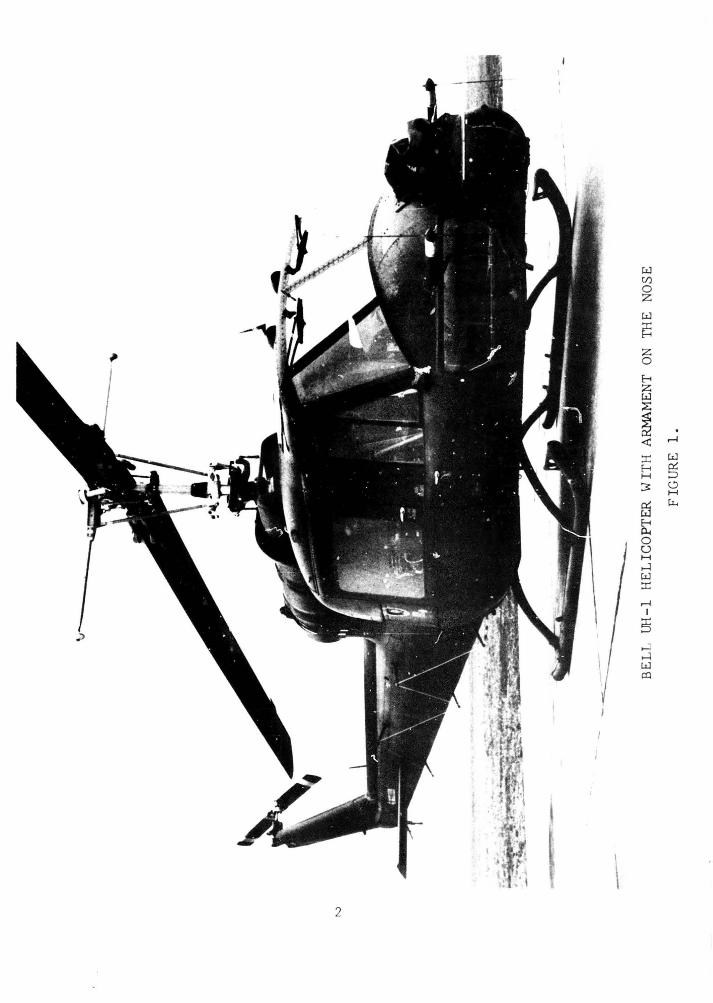
There are many requirements for the use of radars on helicopters. Despite this, few of the systems that have been tried have been successful. One of the problems Is finding a good location for an antenna. Figure 1 shows the UH-1, a typical helicopter. It sits low to the ground so that there Is little room for an antenna underneath. The nose Is taken up with armament and the rotor system occupies the top of the helicopter. This paper describes the concept of using a helicopter main rotor as a scanning antenna and presents some of the design problems encountered.
Military helicopters often have a mission to fly at low altitudes. It Is desirable that they be able to perform this mission at night and during low visibility. The pilots and crewmen need to navi- gate and locate enemy targets, landing areas, or other geographi- cal landmarks. They, ef course, need to avoid obstacles, which In the low altitude mission are often trees, poles, or minor ter- rain features. The ranges at which the Information Is desired are usually short.
The specific radar requirements to provide the desired information are (a) sharp resolution, (b) high data rate, (c) weather pene- tration, (d) daylight display, (e) vertical Information. This capability must be achieved within the mounting limitations dis- cussed above. It is necessary that the radar system be small and light in weight for helicopters have far less load capability than fixed wing aircraft.
These general requirements for a lightweight, high resolution, rapid scan helicopter radar prompted us to seriously consider the use of the main rotor as a scanning antenna.
The concept is pictured in Figure 2. A long slotted antenna array would be mounted in each blade and fed from Inside the helicopter through the center of the hollow main mast. A rotary joint is placed at the top of the mast to feed the slotted arrays. In the UH-1 the normal rotor frequency results in a 10 cycle per second scan when using the two antennas.
One of the problem areas in the design of a rotor blade antenna is rotor blade bending. Bell uses a semirigid rotor system in which the blades are firmly restrained at the hub. The blades bend upward during rotation as a result of air loads. This beamwise bending Is a function of rotor speed and for constant control settings, as in normal cruise flight, the cycle by cycle bending is repetitive at all points around the arc. It results in a slight tilt of the antenna pattern in the vertical plane. At the low altitude normal for helicopter operation, no noticeable degradation of the radar picture on a PPI display is expected.
w U)
0 z w t:S z 0
E-t z w ~
~ . <X: r-l
::r: w E-t §5 H
3 (.) H
f:l ~
E-t 0.. 0 0 H ....:l w ::r: r-l
I
!§ ....:l ....:l w o:l
2

BEAM I
GROUND PLANE
BEAMWIOTH 0.33*.
TYPICAL ANTENNA PATTERN
FIGURE 2.
3

The most critical aspect of blade bendinjr is the inplane or chord deflection. For any specific frequency the antenna inplane bending must be held to I/1* wavelengths of the radar frequency in order to prevent serious defocusin? of the antenna. To determine the blade deflections encountered at 120 knot level flight, a program was developed to compute blade deflections using bending moments measured in a flight strain survey of the UH-1B helicopter. The bending moments measured in a 126 knot level flight condition were programed into the computer. The resulting inplane deflec- tions computed with this program were very small. The deflection curves for the 126 knot condition are shown in Figure 3. It shows the approximate magnitude of the deflections at different azimuth stations. The outboard 50 per cent of the blade is almost straight, and the majority of the blade bending occurs in the region inboard of 25 per cent radius.
A Ku band antenna could effectively use approximately 15 feet of the rotor blade length for a full 360 degrees of scan and not ex- ceed l/k of the wavelength In chordwise bending.
Another factor that must be considered is the blade pitch motion. A helicopter in flight exhibits cyclic changes in blade pitch (oscillatory feathering angle) as the blade rotates. Typically, the magnitude of the oscillatory feathering angle will be on the order of ±2 to 6 degrees. It can be seen that with a total verti- cal angle of 38 degrees which we have measured it is possible to Illuminate targets on even rough terrain in cruise flight. It is not considered feasible to use the radar during large roll and pitch attitude changes.
The problems of embedding a slotted array in the blade and providing windows transparent to microwave energy can be solved with existing technology. Figure 4 shows the construction of a UH-1 rotor blade. It consists of a main box beam member with an aluminum honeycomb body aft of the box beam. An aluminum spar forms the trailing edge and a brass spar forms the leading edge. Figure 5 shows how the brass spar has been milled away to provide a slot in which a K band waveguide can be inserted. Figure 6 shows the waveguide being inserted in a full length blade. The waveguide is then bonded in place and is covered with a polyurethane boot for erosion protec- tion.
The trailing edge antenna is a bit more difficult to install. F-fgure 7 shows how the trailing edge spar has been modified to accept the waveguide. Here it is necessary to form a fiberglas trailing edge fairing to maintain the correct aerodynamic shape.
Both the leading and trailing edge designs are feasible, and are quite practical from the helicopter operation standpoint.

S o
N
K in X
o o u. «■■M
c -1
< III > u .
Si o Ul
(0 N
UJ >
0 < a: i
o (A »- z O
o Z
H (0 O w ÜJ N J Ul Ü. 3 UJ o 1 UJ o
1 UJ
!
§1 ¥S § o _J U ! T
° S CSI K> I
j 4^ •- f j "7 "1/ , ... , ,. .. w —h*~
/
....;....
CO
U
g E
.. .. j ,,,;... .... ij 1
—r - ■ t 17
/ i ' E_j.... ...:....
§ ...... ... . :....
/ /
•■ -p- ■'\M 1 ...|... ...:■....
__:... . 1 1 | ....j.-. ~f."~
/ ._ ....
8 f /
>■■■
.._ i
—1_.. ■;■■ 1 r ! / .... — .... ~
■ i
i i 1 JL M /R H~
j '"I"" ri f
/ HI Ti
j . ,. ..|„.. f f -8 _i | - H l /
- t
UJ /' i 5 —1 : 1
i f \i -I- O
N (
IN
140 i\) r / .:
■1 w 1 —• ■
_~ — ■ 1 .—t... .. .....
E 11/7 ' i — 1
^O 11 ilti 1 :
(AM —r— i f i '.:.. ii ... ___!
Ul !
< •■• • 11 f 1
i
1 1:
.._ —: _4..-. «S III 2 —I- ■■ • 11 / — .„
mu / 1 ^_4-_
St 1 ■ i ; ' 00
........ :. .. .;._ i j
• 1 1 ■
.._;. .. o | I r (0
•■ i • -j— ..„:__ ....|._. —
i
■ i l
...... ■■ •••••
? i '
i ■ -i--- ....;...
i i
o t . j CM
. ...... -f- ...,_.
O M ...j._ ...\— -i-
1
o q o q o - eg « ♦
^-OWVMdOd ONIONSe UV 9NI0N38-> (S3H0NI) N0ll031J3a

CROSS SECTION OF ROTOR BlADE SHOWit--;G LEA D I NC EDG E ANTENNA SLOT
FI GU RE l..j
FJCl'RE ')
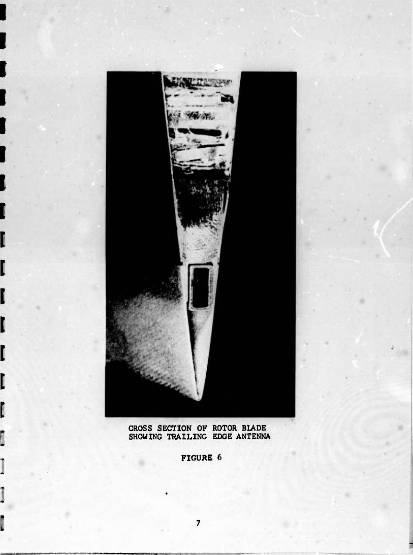
CROSS SECTION OF ROTOR BLADE SHOWING TRAILING EDGE ANTENNA
FIGURE 6

0:: 0 E-< 0 0::
1=0 ...-i
r-. I
5 w 0:: ;:::::,
li< <.)
0 H li<

2. ANTENNA DESIGN SUMMARY
The cutoff element array technique la applicable to both the leading and trallln? ed^es of the rotor blade, Indeed It appears the exact same antenna configuration may be used In both the leading and trailing edges. Short antennas were tested in both the leading and trailing edges of the blade with excellent results, but only the leading edge antenna was made full length (173.3 Inch aperture). The full length antenna can be tested out of the blade or in the blade for there is little or no difference in the azimuth pattern in either case. The sidelobes and beam- width change with application of the erosion boot to the leading edge of the blade containing the antenna Is negligible. There is a loss of gain of about 1.5 db with .055 Inch thick Estane and less loss with thinner pieces. The radiating elements, beinp at cutoff and certainly not resonant, are affected very little by changes in the element environment caused by the application of erosion material (leading edge), fiberglas cap (trailing edge), and proximity of metal (array in or array out of blade).
The leaky wave mode of radiation was used throughout and although the 30 degree end-fire from broadside beam reduces the effective aperture from 173.3 inches to 150 Inches, the experienced phase stability was quite satisfactory. The phase Is essentially Inde- pendent of hole spacing in the final 173 Inch antenna. However, large changes in hole spacing in the narrow wall of the waveguide will cause a phase error. This error can be compensated by ad- justing the "a" dimension of the waveguide. However, holes In the broadside of the guide, and not too near the edge of the guide, do not cause appreciable phase error. Very large cutoff holes in the narrow side of the guide make the guide appreciably larger, providing a lower than normal cutoff frequency for the guide. The cutoff element technique seems to be particularly applicable to long arrays because of the small required coupling between the radiating element and the waveguide transmission line (about 17 to U0 db).
The thin wall of the waveguide keeps the loss due to the cutoff characteristic of the hole element radiator to about 1 db or less. A nominal wall thickness of .010 inch provides satisfactory re- sults. Control of the wall thickness and of the .030 inch by 173 Inch opening above the holes Is fairly critical, and poor adjust- ment and Improper handling can raise sidelobe levels from 30 db to 25 db. The proper design sidelobe level suggested 40 db sidelobes, but construction tolerances provided about 30 db sidelobes. A 5 db change in sidelobe level at the low level of 30 db can in general antenna practice occur quite easily. The elevation beam- width of the Rotor Blade Antenna Is about 38 degrees which makes measurement of low sidelobe levels difficult. It is possible that the coming flight tests may provide better results than the static field tests because of the obstruction free test site provided by a helicopter at altitude. However, little difference is expected between static field and flying antenna performance data.
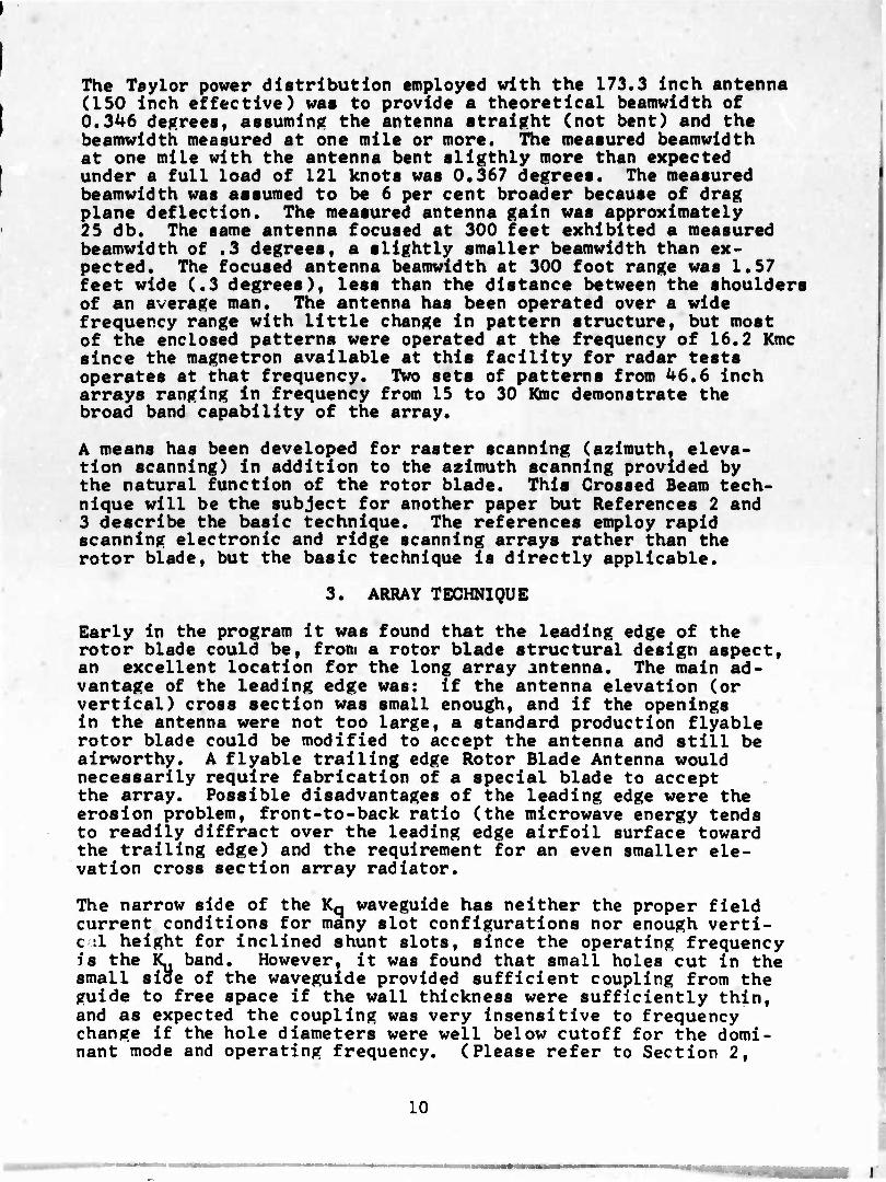
The Teylor power distribution employed with the 173.3 Inch antenna (ISO Inch effective) was to provide a theoretical beamwidth of 0.346 decrees, assuming the antenna straight (not bent) and the beamwidth measured at one mile or more. The measured beamwidth at one mile with the antenna bent sllgthly more than expected under a full load of 121 knots was 0.367 degrees. The measured beamwidth was assumed to be 6 per cent broader because of drag plane deflection. The measured antenna gain was approximately 25 db. The same antenna focused at 300 feet exhibited a measured beamwidth of .3 degrees, a slightly smaller beamwidth than ex- pected. The focused antenna beamwidth at 300 foot range was 1.57 feet wide (.3 degrees), less than the distance between the shoulders of an average man. The antenna has been operated over a wide frequency range with little change In pattern structure, but most of the enclosed patterns were operated at the frequency of 16.2 Kmc since the magnetron available at this facility for radar tests operates at that frequency. Two sets of patterns from U6.6 inch arrays ranging in frequency from 15 to 30 Kmc demonstrate the broad band capability of the array.
A means has been developed for raster scanning (azimuth, eleva- tion scanning) in addition to the azimuth scanning provided by the natural function of the rotor blade. This Crossed Beam tech- nique will be the subject for another paper but References 2 and 3 describe the basic technique. The references employ rapid scanning electronic and ridge scanning arrays rather than the rotor blade, but the basic technique is directly applicable.
3. ARRAY TECHNIQUE
Early in the program it was found that the leading edge of the rotor blade could be, from a rotor blade structural design aspect, an excellent location for the long array antenna. The main ad- vantage of the leading edge was: if the antenna elevation (or vertical) cross section was small enough, and if the openings in the antenna were not too large, a standard production flyable rotor blade could be modified to accept the antenna and still be airworthy. A flyable trailing edge Rotor Blade Antenna would necessarily require fabrication of a special blade to accept the array. Possible disadvantages of the leading edge were the erosion problem, front-to-back ratio (the microwave energy tends to readily diffract over the leading edge airfoil surface toward the trailing edge) and the requirement for an even smaller ele- vation cross section array radiator.
The narrow side of the Kq waveguide has neither the proper field current conditions for many slot configurations nor enough verti- cil height for inclined shunt slots, since the operating frequency is the Ky band. However, it was found that small holes cut in the small side of the waveguide provided sufficient coupling from the guide to free space if the wall thickness were sufficiently thin, and as expected the coupling was very insensitive to frequency change if the hole diameters were well below cutoff for the domi- nant mode and operating frequency. (Please refer to Section 2,
10

Antenna Design Summary.) However, it was found that change in hole size apparently affected the cutoff characteristic of the waveguide (changed the wavelength in the guide) and therefore changed both the emerging phase front and thus the beam angle. The broad dimension of the waveguide ("a") could have been slightly decreased to prevent this phase error but it was decided to move the holes to the broad side of the guide. Here too it was found that the holes introduced phase error, but as the holes were moved closer to the longitudinal centerline of the waveguide, the cou- pling reduced slightly, but the phase error rapidly reduced to a negligible value. The holes can be used in the narrow side, there is no doubt, but most of the remaining work reported here Is with the holes in the broad side. When a portion of the broad wall is cut away to provide a thin wall for the holes, this same cut away volume can be used as a secondary radiating aperture area, finally leading to a very small cross section radiator. It was found that the coupling to the opening above the holes was quite sensitive to variations in the dimensions of the opening. A thin .010 inch brass plate now covers the holes and good con- ductivity is assured (soldered) at the joint of the plate and the waveguide. The plate provided the required structural in- tegrity and the electrical conductivity at the junction of the waveguide with the plate. With the plate added, the antenna per- formed equally well both in and out of the rotor blade. With electrical stability the array assembly could be epoxled into the rotor blade without critical mechanical features or critical con- ductivity, 'installation of the array is not critical and requires only good aerodynamic practice. The Ka waveguide with its .040 inch wall thickness and 0.25 inch x 0.3 inch outside dimension is the fundamental structure of all arrays demonstrated and reported in this report.
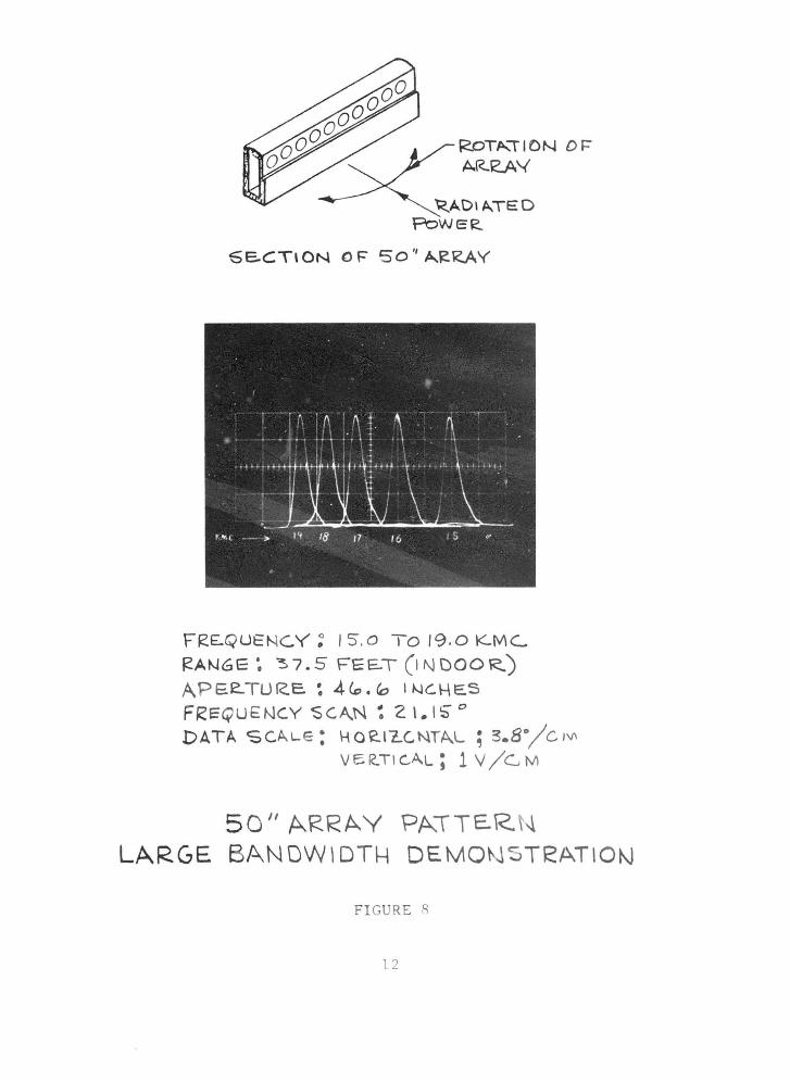
Figure 8 demonstrates the broadband capability of the cutoff ele- ment array using the leaky wave mode. The sine of the angle of the main beam with respect to broadside is proportional to the ratio of the free space wavelength to the wavelength in the guide. Change in frequency causes a corresponding change in beam angle, but unlike resonant slots with critical slot spacing, the pattern shape generated by the cutoff element, leaky wave array, is largely independent of frequency.
The antenna is more broad band without the use of the opening in the brass nose section of the rotor blade, probably due to the frequency sensitivity of the short at the junction of the brass leading edge with the waveguide back of the hole elements. How- ever, Figure 9 adequately demonstrates the broad band capability of the array in the brass leading edge. Figure 10 is a plot of the normalized relative gain of a horn whose gain varies with the square of the free space wavelength and the gain of the array, which is assumed to vary only as a function of wavelength. Theoretical and measured gains are shown.
11
'<_ADI A.TE:D 'Pc>WER.
6E..CT\ON 0 F So'' AJ!R.AV
FgE.Q UENC.V' ~ I S.o To 19.0 K-MC..
RA~6E ~ ~ 7. 5 FEE-T (1 N DOOR.) APEe.TUR.E.: 4Co.'=' I~C.HE.S
F~EQUE~CY SC.A.N ~ 21.15"" DATA SCAL-E: H0£..1"Z..C.NTA.L; 3.8°/CM
VF-R.TI GAL; 1 V /G M
50 '' ARRAY ?A.\TE.R t~
LARGE BANDWlDT~ DEMON TeATIO~
FI GUR E q
l2

BRASS RCIO R. B LA.OE l-l0S&PI £CE
f:"REQUENCY: \ 5 .0 TO 1'? . 0 I<..MC...
'?.ANG E : 31. S' FEET (11\.1 DOO RJ APE f( TU R E : 4 '- . 10 I N C. H E.~
ROTA.TlON OF AARAV
DATA ~ C.A.LE.: H OK.I C. 0 NTAL; "3. 8 :/c.M
FRE.QUENC.Y ( K. \'v\ c..)
15
vs:e11 c.AL ; 1 v 1 c. M P~I~(IPA.L- LOBE (t>EC.~E~, ENO~I I::E.I=I(Dv\ B~ADSI Ds.)
2. 3. 0 \ ~ 2'3,'5"
\1 '3 "'· 0 18 40,0
\ ~ 44.0
50"A.RRAY PAITERN LARGE BA-NDWIDTH DEMONSTRAI\ON
FIGURE 9
l3

>, 4» cd CO U
4-> § w < • c e > . »0» «H c «< (WO c
•H CX r-t 4) -H CO 4-1 (M O ^ r-l B
C 0 Ufa CO W TJ ax • •>
•H C C co : : CO CO 0 J- JS B OJ-
•H q «H co bc 3 F-( o\ •H •.P •H B CN O
c co^ Ü -JS «H • •H bü'U c
cO ^3 ; c § O •'•H 3 (4
bO C (4-1 et >>S B 0) J- (H CO 'HU
0) 0 0 <u ...B .131 > X w •H C U -d cd 'o B cd 4J O « (U cd «H CO •••H > b 4-» O -O
^«<-»-» c 3 Bi3r a> ü«H co 0) 4-4, b (M C CO E co^
.O 3 c 0) a»'H o o TJ (4-1 CO X r-4 .J3 (U c <U U
4-1 0 0» CO CO u bog u •H CO 'H c ■4-1 ^ c 9 •
•H 4-) U c 4-1 o «H E r TD owe 01 O Q< O *H C0 (U C >'H 4-» •P CO XvO t- S C CO c B (« a^|o
O O CO X • cu U^'H ÖC <
a C/J
L X J.
0
0
ü 52
2 U)
s
»O «sj «. o
(U
0) CO
(U
o CO
CO 'H
CO
2
*
|4-) U H
14
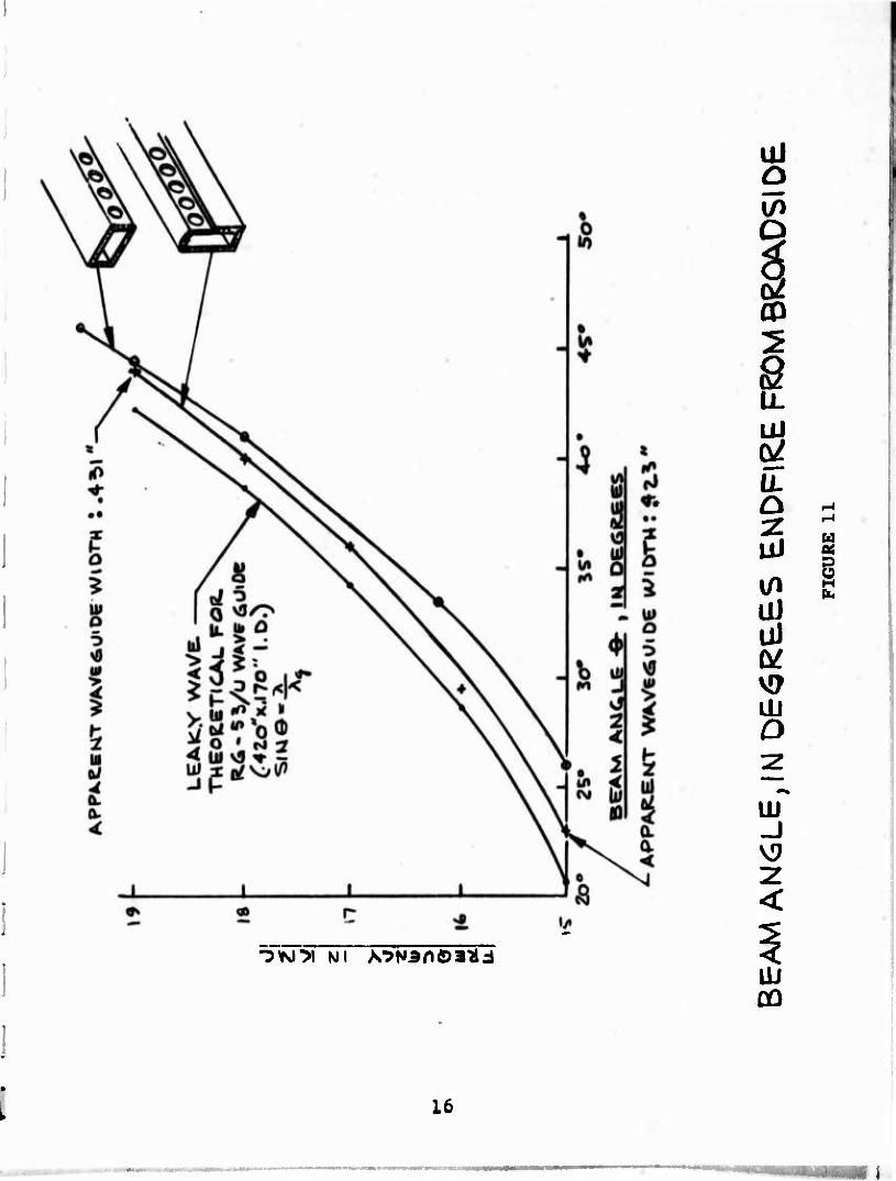
When the data for Figure II were taken It was not Intended to Indicate effective dimensional change in the waveguide broad dimension (a) with hole position, and the data taken may not be accurate enough, but it is certain that holes in the narrow side do increase the "a" dimension effectively by lowering the cutoff frequency or decreasing the wavelength in the guide. The extreme hole diameters used in the 173.3 inch array were found to exhibit little phase error. Why the curve which demonstrates radiation from holes in the broadside (near the center line) is not coinci- dent with the theoretical curve, is not quite certain. However, the lower ends of the curve are within the specified tolerance of the waveguide as given by the original manufacturer.
While the bandwidth of the array in the brass leading edge is less than in free space (no brass plate), the bandwidth of the array in either condition is greater than the HP-628A signal generator bandwidth which was used for these pattern measure- ments. The only limit to bandwidth of the basic array is probably the transmission line and perhaps a ridged line would give greater bandwidth. An octave bandwidth does seem a possibility (2/1 fre- quency change).
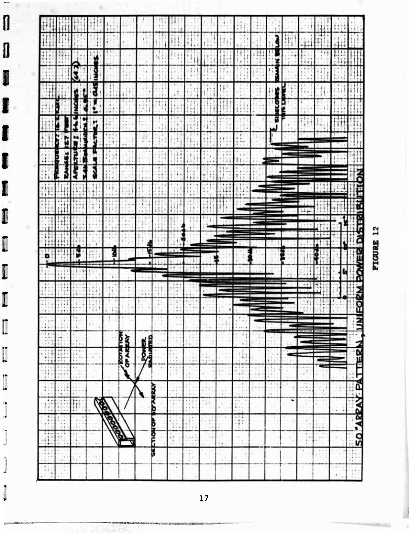
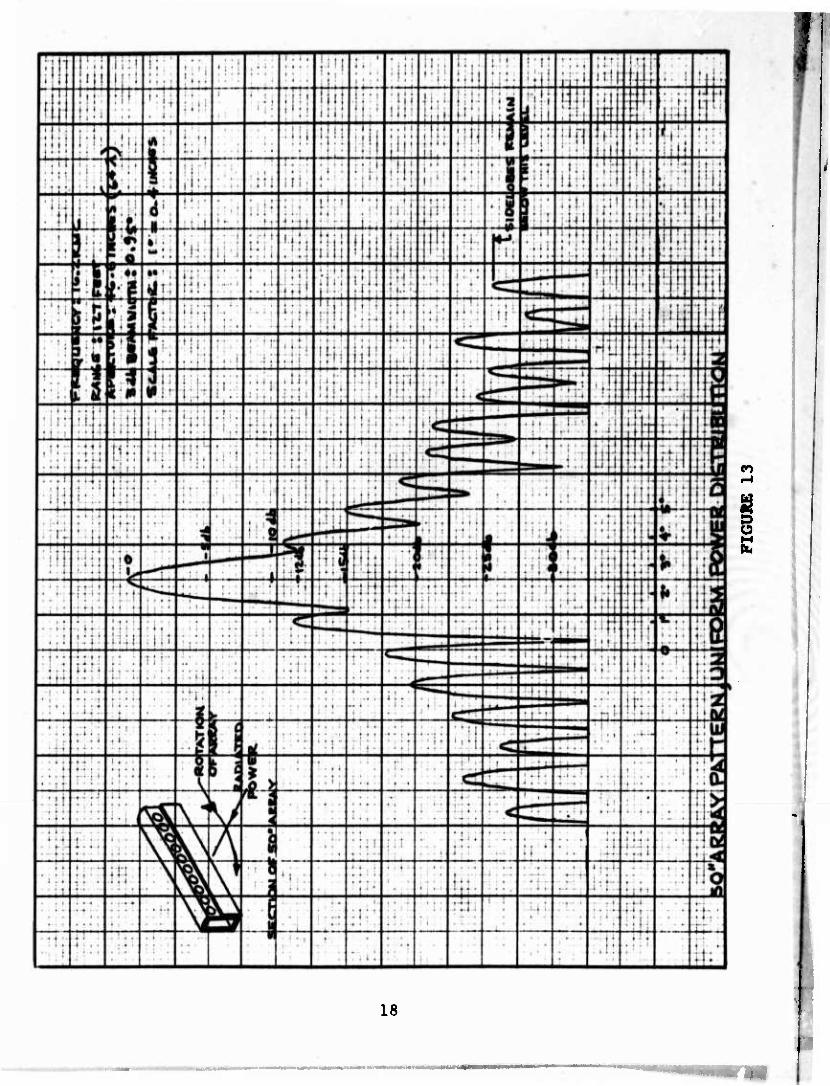
Figures 8 and 9 used symmetrical power coupling about the center of the array, while using a high per cent of power in the load to achieve a near symmetrical power taper. Figures 12 and 13 used the same array with constant coupling (holes to the trans- mission line) and a high per cent of power in the load to achieve a nearly uniform power distribution. These patterns were all used to confirm phase linearity prior to building the long array.
Figure Ik is representative of the final basic array configuration of short length (46.4 inches). Note particularly the sketch of the array which is different than the preceding figures. The final basic array form shown in Figure 14 contains the brass plate as an integral part of the basic array and the .030 inch slit is the secondary radiator.
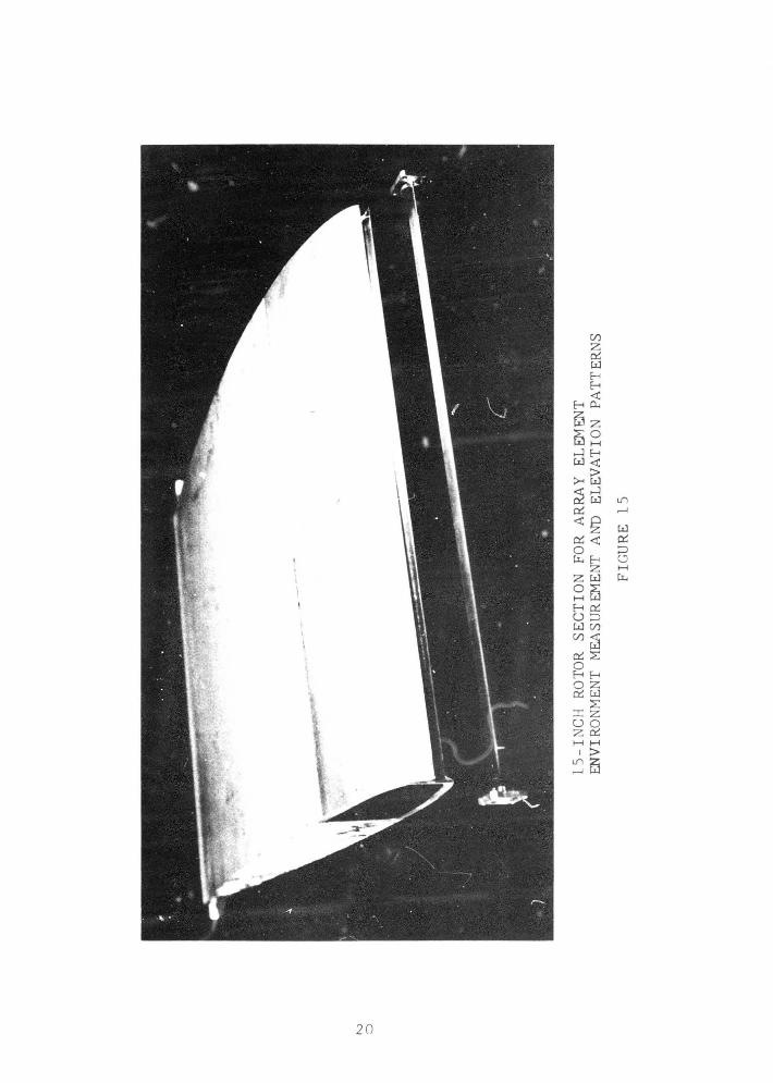
4. FRONT TO BACK RATIO
Fifteen-inch rotor blade sections were cut to aid in detailed measurements of the element radiator environments and some of these same sections were used for elevation pattern measurements, but it was soon realized that new sections cut on a 30 degree bias had to be prepared to make meaningful front to back ratio measure- ments with convenient short sections. Figures 15 and 16 are typical of the square cut sections. The array shown has holes in the broad side and is not typical, but the slot in the leading edge of the rotor blade section and the trailing edge configura- tion is typical.^ The remaining small blade sections were cut on a 30 degree bias because the beam angle is 30 degrees from the broad side. This angle is typical of the leaky wave mode with a wavelength in the guide twice the length of the free space wavelength. Both the forward main lobe and a diffraction lobe to the rear are 30 degrees from the broad side beams.
15
Ö s
^y^i^i Ni A^Nanöa^lJ
Üi Ul
ÜJ o
UJ -J
<
ÜJ GO
i
16
17
I Ü
18

11
-I -; j i ... 1 ; ; • ■ i . . ... , T":.:.
:.r;: > - > 4 •
''.'. .:.': '■' ■ ■: : • •
'■' i
..t •• i i .'. i ; i. J i«-
..-.,_ . . . . .. (...,,
:': • .'.. \ '..:
r | ( ■ i.. ■ 11: .-* • 4
iff; ■ j '
■: M :,i-i
#
' ' ; ' ::i * i < •
■ 1 i ■;'. }.'.. 1; 111
■ u
*. * ; : | j i . •. j
-
_ » " • ■"■f. ■ ■... i
j t ■
-j I '.! i ! r • - 1 • .
■ ■
■ t 'it!
■ •»
• i ■ ■ ; ( • * -1 •
. i ■ ! Iff
" "* —
i H '
\ US «
":'i 1 I r| J • f « .
> .: . ! '
; i ; r
1!' i c rrf t -< t ■ • 1 . ' - I ;.i i"::
1 ■
m 5- *«. *
i M ■ ■ ! .
1 t ■ - i 1 • 1 1
: 1 i .'■. ■... |
• It i
11;
" ■ t ir- -* >: . 'i
' ' • r ' ( : f iLi.
r : 3«iZ .: i. ': ■'
'';: I * '■
i • ;
' •■ 1
' • • I- : ' ,
' !•'■,
•f! 1 • .. i i f'fl i
t . ' '
% lit-1 Ü
•■: I :
j :.i
1 pi n i-l livi fjil firi t
[J jil] fill ! ' ' ' , : : , _< ! i . ■ . 1 1 '
\ i . !
t • t :i ;■ t- * .
; r' ; i;: •
Itli . i.; (•It 1 1,
14* * i ::, ;<: ^^^^ :: : i. M jjii In
1
f • - ...., > 111 jTn
i ; i i * M i 1 ■
11 .
I . i i
;.: tf. . M .' 11
* - 4
• 1 ' • [jjj 1 i ! '
11. • . . . i ; . . <d rr1
:.;.:.. ] j"
ij .... El
D i:"ji 1 ! • '■':'<■'
■ . i ( ■ • * 1 1 ii { i 1 i
■ J ■ ■ «■
[•H-j i *. | l^f 1 ■ !
r f ' : ' 1 'ill
* f • i ! i i;: ?':i
. , ■ i '. i
1:! r [ii'l m 4 : < . Ml ! i ' j i •
. ■. .j jlffl i. ....
! ' U; .j.j
i i ■" ; • f !
tn R? r ^
V
nit •11! i '. ' 1 j , ; ! '
8 M V ■ t
■':
1
( ! ' i
liiij • . T. jij •iT , .'. i ill" • -1 ■
; T • :
1 • 1 4 f
-■.': i ! ! : ,1
. • ; ; > Ii',. tin
r 1 j ^ j mi . j. 1
liif • I ■
i-'li i i H: *"*"
\ • i !!t: • • I ; Üf j .: ' ! '
i 1 ' .1 :! ■ ■!
1 Rj i ! w
i ' *q ■ ■ ^P ■ ■: 1
m 11 •
■ i i • »- . t i 1 ; [Hi
j. j i J A- 1 t ■
r * f ... 1 .
» ■ •
1- , . 1
i , <: m
It. !i I I LI
t )■ < ■ ■ i-
1 : ■
V • III'
••ill h|i i :: i • Ii 1 i ' '.
. t ■'. 1
i i * • ;:- liii M #r 1 j If
1 I
<
1 M n
11 • i j-t
r • • t
f j lH i i >
i • •
! 1 HI , 1
: r T
-1 ■ t
it:* ■ u iff!
; I.,
. : . i ■ : -1
U r • i l;fi : i ' ■
- , : : . n
'IM •ii; !•: ■
W m i f ; 'Hi
f ' ' . . i ii!! i;!; . P ; ' i ■ • (-'!. [In
H ! r ' 1 : :i; ? i •
• i i • • 1 :.'::
; •' •
< ^
A 7 ' . . i f ■ • ■
. . . i! jl 1 . 1
i i . .: i!
i 1 1 j ! j! 1
j "Hi
J ■•1
i ■ ■
[ j j i i ■ t
• 5 i 0 r
1 .' 1 . 1 : ' • ■ t :
■ ■*■ i ' • 1 ' 1
111 ■ i ! i j * 1(1'
1!' ! rr: . V |
t ' . 1
'! i P
, ii i|H (f| \ f h i • 1 t
• I I
i I'; ! 'Hi
i J i . i 1 t M 1 fji r s E
■:;
■i:! ;:': :! u : j ' ; ; ■ r
; 1 1
1 i ' ij ; I , :;' i
v..j . . ' '
.'H < • r f i'l i j :::: i' • * 'iji
;! 11 i i.'. 1':;
» I •' 1 i j [ in:
* • 1 i • ■
i ■ ' i . ; i i :.5
: ! ! ■ t '
. J1
■ ■:: :'. 'i :i ^ ; • [''
i ■ '
* ' i
r • t i
! . i i t 111
i ■ ■, ' ' t- ' ,1 : ij ' 1 i 1 ' r- —r—
i ':::" 1 ■ • ■ t'
:ff1 4'! nii .;
:! Ii 1 , 1 jM j
i : . i
i . t .
■ 1: ; • 1 •
19
•
s
N
0
15-I
NC
H
ROTO
R SE
CT
ION
FO
R
ARR
AY
EL
EMEN
T EN
VIR
ON
MEN
T M
EASU
REM
ENT
AN
D
ELEV
ATI
ON
PA
TTER
NS
FIG
UR
E
15


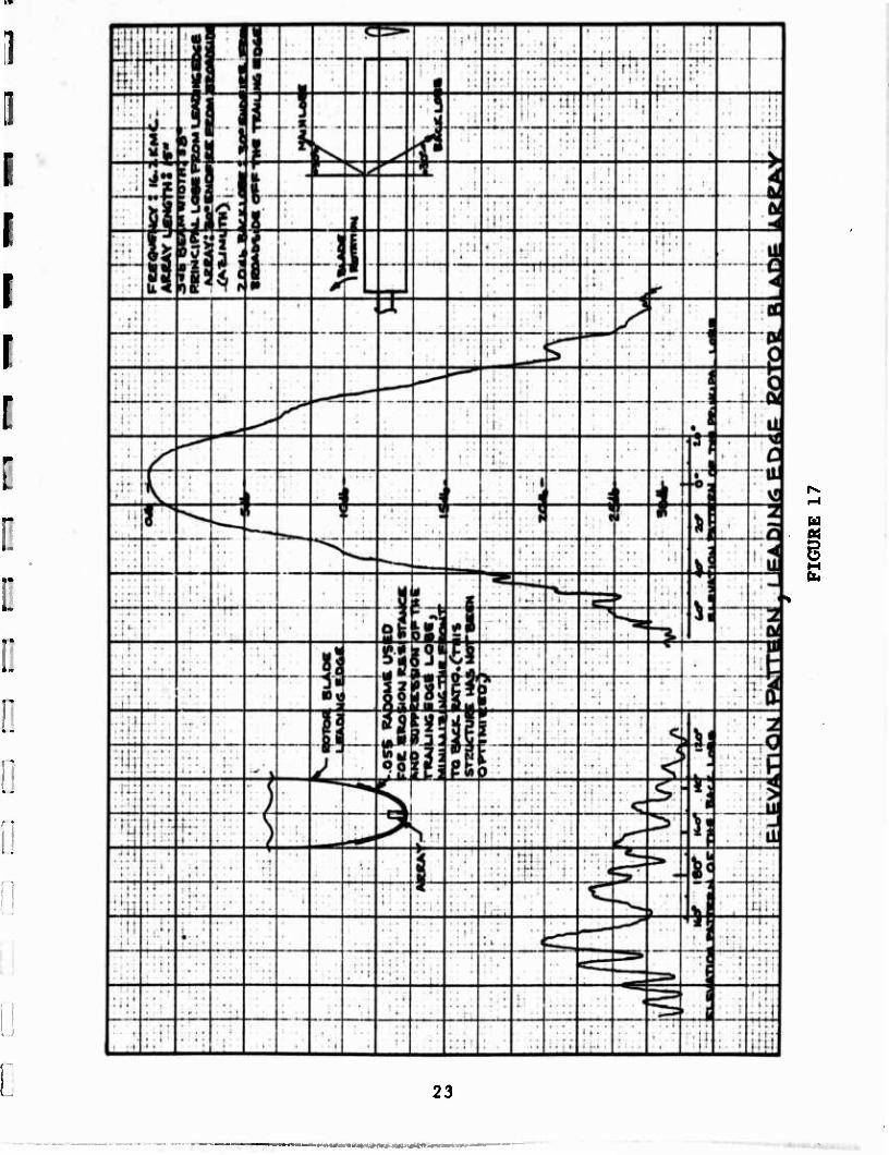
Fisrure 17 Is the elevation pattern of both the forward and reverse lobe with the complete final assembly, including the proper com- bination of Estane and Neoprene to provide both erosion and sup- pression (front to back ratio) has not been optimized, 20 db is believed satisfactory. Twenty-five db should not be very diffi- cult to achieve, but 30 db will be quite a bit more difficult. The back lobe is a surface wave and has rather small elevation bearawldth, having an effective aperture of about seven inches. Perhaps this feature could be put to good use, but for the present program the surface wave effect serves no useful purpose.
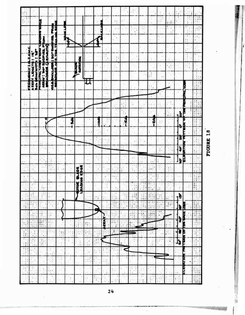
Figure 18 is the elevation pattern of a leading edge antenna with- out Neoprene. Thus, the back beam is not absorbed. This back lobe causes no difficulty if the rotor blade is used to transmit and a vertical antenna is used for receiving (Crossed Beam Tech- nique). Since the vertical antenna will have a braod azimuth pattern but probably no more than 180 degrees, the receiving antenna may be switched off when the back lobe from the helicop- ter blade passes into the visible frontal view. However, when the rotor blade is used for both transmit and receive, the back lobe is no different than any other side lobe and may cause a serious display error by printing each obstacle twice, one cor- rectly and one displayed 120 degrees (a considerable error). However, the 20 db sidelobe level provided by the microwave ab- sorbent Neoprene is quite sufficient for most performance require- ments.
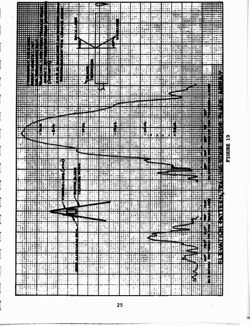
The trailing edge antenna (Figure 19) performs quite well and has much less tendency to produce a lobe toward the leading edge (naturally good front to back ratio). A small, very thin conduc- tive sheet is required to balance the back radiation toward the leading edge to minimize the back lobe. Again, the back lobe suppression has not been optimized, but the 20 db is believed to be satisfactory. Good front to back ratio seems somewhat easier to provide with the trailing edge antenna. There is very little transmission difficulty with the fiberglas airfoil fairing.
5. 173.3 INCH ARRAY DESIGN
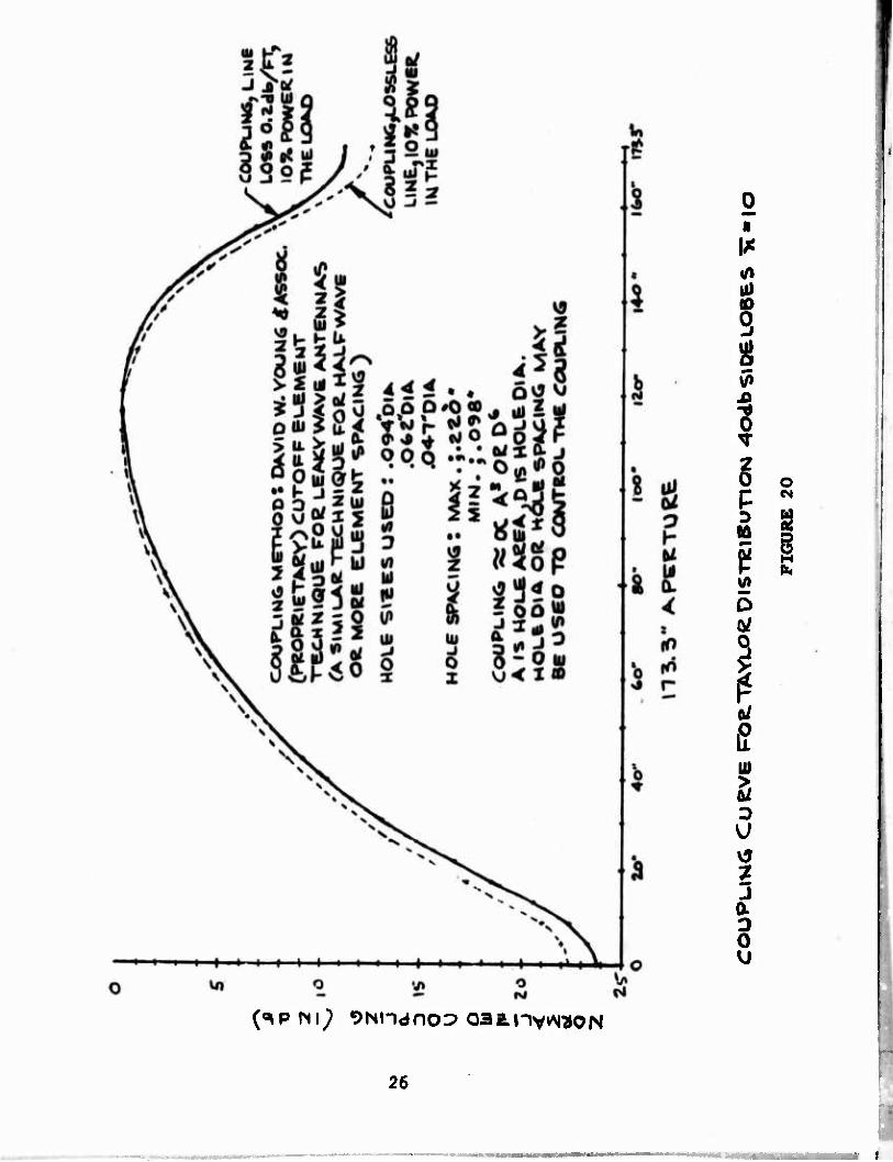
Figure 20 is a plot of the hole coupling as a function of the position on the array. The method of calculating coupling, to- gether with the variation In hole sizes used, and the effects of a Lossy transmission line are shown. The statement in paren- thesis "(a similar technique for half wave or more spacing)" was meant to imply the cutoff hole technique could be used for an array which used element spacing to determine the main beam angle, usually a half wavelength or more. While the curve shown was normalized, the peak value of coupling (the closest coupling) was about 17 db. The transmission line loss reduced the gain of the antenna 1.5 db, a reasonably small figure.
22
u 01$
23
00
u
2k
25
(«ipm^ ^Nndnop oaanvkM^ON
o CM
26
■tii '

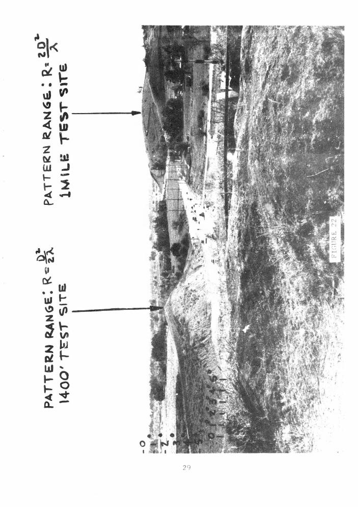
Fljrure 21 Itemizes the equipment used to provide the patterns for the full length Rotor Blade Antenna. The figure further details the instrumentation schematic and the physical layout of the equipment. The actual antenna pattern measurement site is shown in Figure 22. Both the Rayleigh range and the far field range is shown.
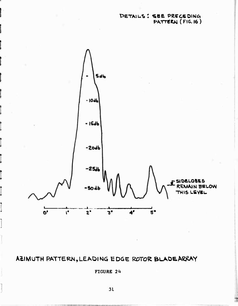
Figures 23. 2^f and 25 are final patterns of the finished array. Figure 23 is most complete and the data detailed on Figure 23 apply equally well to Figure 2k and largely to Figure 25. Figure 23 and Figure 2U differ slightly in sidelobe structure and level, and it is not known why, but this small change in sidelobe level can occur because of the broad elevation beamwidth of the array and slight scattering from the ground cover. Most of the differ- ence in Figures 23 and 2k is scale factor, however. The data itemized are self-explanatory.
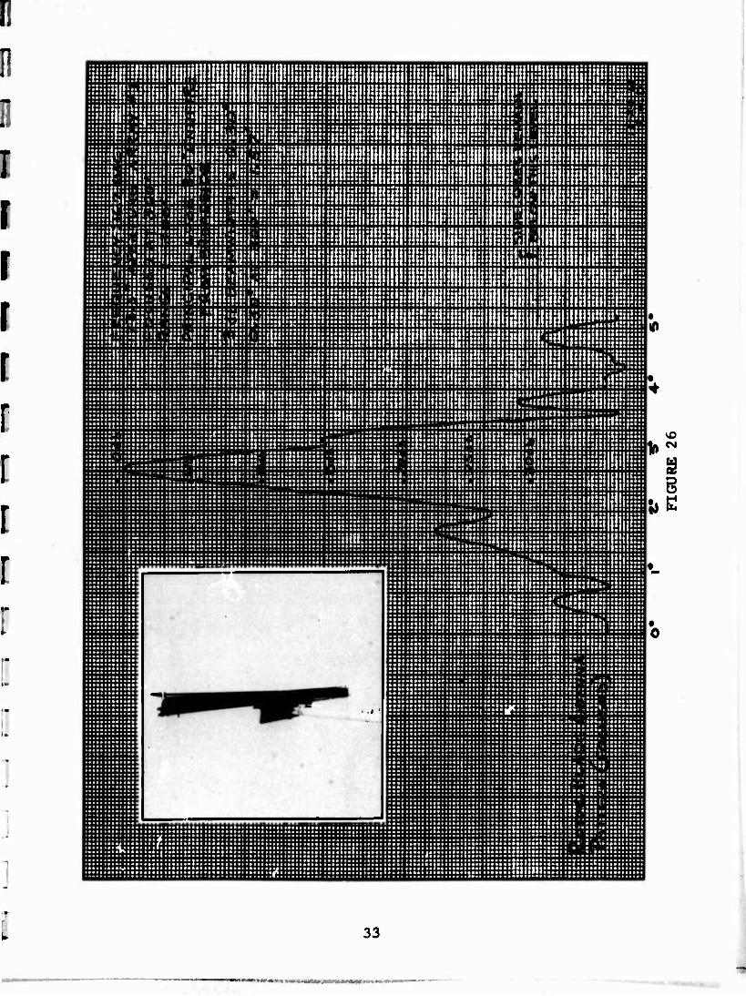
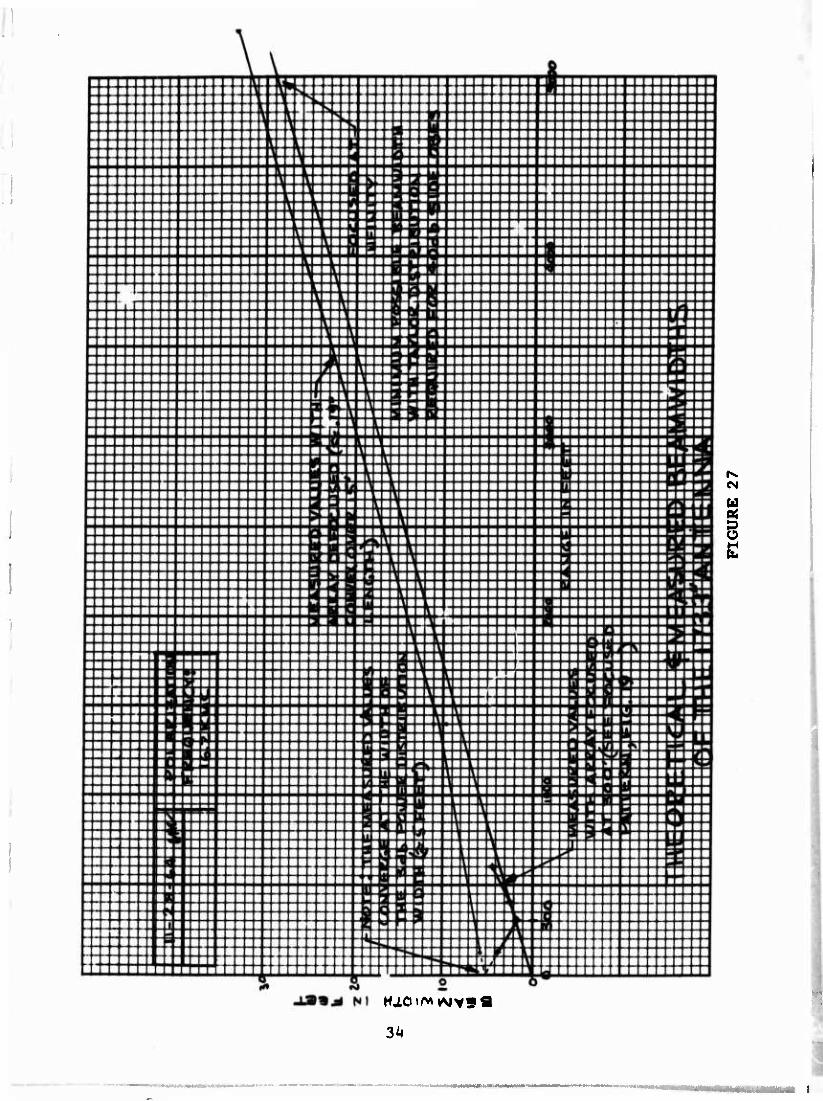
6. EFFECTS OF FOCUSING
There are only two figures with this section. Figure 26 and Figure 27. At first glance the figures are deceptively simple and seem of little significance, but the relationship between an antenna focused in the near field and the far field and the relationship between the resolution of an array in the near field, when focused at infinity, or slightly defocused, is seldom under- stood. The following measurements may make these resolution relations at 3 db clearer for this particular 173.3 inch antenna.
Figure 26 is the pattern of the 173,3 inch array focused at 300 feet and exhibits low sidelobes and a beamwidth of 1.57 feet, corresponding to 0.3 degrees.
Figure 27 Illustrates the following: the beamwidth of the array measured in feet is the same at the aperture for all conditions of phase Including focus at near and far field and defocused. The beamwidth at the aperture is simply the power distribution of the array, in this case the Taylor distribution for kO db side- lobes, IT ■ 10. If the antenna had a uniform power distribution Instead of the symmetrical power taper, the beamwidth at the aperture would be about 15 feet instead of 5 feet. The beamwidth of the focused antenna is not a point (or line) as in geometric optics, but is limited to the basic beamwidth of the array. The beamwidth of the array at distances other than the focal distance is shown at the left side of Figure 27, While comparing the measured beamwidth in feet for the array under full load conditions (slightly defocused) at various ranges (it is not a straight line function) it is interesting to remember that beamwidth in the far field is proportional to the ratio of array aperture to wavelength, while the Rayleigh range is proportional to the ratio of the array aper- ture squared to the wavelength, which might suggest a higher operating frequency for the same resolution with a subsequent reduction in the Rayleigh range. However, the antenna can only be effectively focused for improved resolution in the Rayleigh ran?e. No conclusion has been drawn but these relations are being
27

:
•
S 5 u «
7— So Ul z k
mi 2gu»0
i >>
Ul 2
i
t- i
^
9 i
Of 1
0/ b
i
28
29

30
PATTÄRJsi ( FIG. 16 )
SlDCLOftES ' REMAIN B6L0>^ TW\S L6VBU
O* 2' 4* 5*
AZIMUTH PATTERM,LEADING EDGE RDTO^ ^LAD6.A^AY
FIGURE 24
31

FIGURE 2 5
32
iiiiiliiliiliffly M iiliil!i;H||liiii!!!t::;|!ii[!!liiJlilii!iiiiii^
!iiHiln;^!lii!lil!!!iili!ii!iii;i!i::^illl!!!lil!ilJ!li iiiiili:|!ill!liPi.!!ii!!!ii!iiliiiiiilli!l!!iy iiii!ii:4ijyiillii!!i!liiii!iilil!!!iiliill^
iiiili!?iii::iiai;iiil!i|;iiil!Bliiia!liiiliiiiH iiii"!iii|l!!i!iiii!ii:!i;Oili;!!ii!li!ii!iliii!i liiliisiiiii^iiinii^llil-'lliiiiiiiiiliiiil!^ illiiilvlsiK^iiiililJIiHiiiiSiiilliiillii!!^ iiiyi!!i|[;iiii:i!lli:i!lli!iiijiiliji!ililliilli iiiilliiiiillliiiiiiliilliiiiilillS!^^^
iiiiiiiiiliiiiiliiiillilillliiiiiliiiiiiiiiyiill!^ I::::::::::::::::::::::::::::;:::::::::::::::::::::::::::::: ::u|u::t:::;3::::::::::^
:::::::'.:;:::::::::;:::::vv;:!::......<:: ::;;::i:t::::::..:::::;;:::;{::::,..:t:|::::{::::::;-::::;:::;:;t:Kici:i::;:::::::t: Unlit":
::::::;::::;!!!;:::::::::!,;5i:::::::::::::.J::;i::::::::::.liiiih:;::::::::;.::^:;::^ ••■••■•■ ••••■■■■••■... ->••■■•*•■■•■( •••••■•■••■■•■■« ■•■•■••!•••••••«■ ■■■■■«••>*•■••■ »■■(••■•■••f<< ••■■>•-■■-.■•■»•■iikaali-»»- ■ ■«■•■•«■■■■•■i«a*il «■«•••■iMaa«.. -••-■••! ■••4taB»*»«*«aiiaa*ia«i*iaaB»i*fä*Maaaaa*«Mt»«>j*«4»«»a*i« •••••••••• a»aa»ti««llb|i|i«*at
■ aaaBiaaaBaaBaaaaaaitMai*t«aaaaia»a*aa*aiaaaaaaaaiaSää«aii»«iB«taa**.- ■--*•* ■ a »*a a a aaaa*t a • aaa al *«*****9 **#**•*■*•!( ••"• ! If *"J 'ill'**'*
i::::::!:::::!:::!::::^!^^:::::::^!::::::::!:::::^ f"!::::! :::::::::::::!:::::::::::::::::::j:::::;:::::::::::::: :::::::H:::H:H:::::H::::::!::HH:H::H::Hn::r':!H::::;i;^ ::::: ::::::iH: I:::::::::;:::;:::::::::::::::::::: :::::::: :::::::::::;:::::::: :::::::!:h:::::!::::::::::::::::::::::::::::::::!::::::::!: ;::n:!::!:::t:St::i:i;?,?!!!l!:i::::i:i::i:!:::::ii:;jS:::i • ■älällläitkZIääääääiääaliääääälääaäääaätiäääääääapIIälääää^ ■ •••..■■..•■■->■■■>•.••••■•>■■■•■*<>••.......<...........■•.......•..••.•■..*-■..•••«>■••..••..••..iiaatt.i.aK.... -aaaaaaaaafaiaataiaaliaaai
- - *■■• «aaaaaaaaaaaaaaaaaaa iataaaaaaiaaaaa*-aaaiaafeiaaaaaaaaiiaaaa«
aaaa afaaatalalaaaaiBaiata«|aaX«XZ|||aaaaaaSB»a«aa, «ala *aa*aaaaai»aa*«*aaaaataaiaaakiaa»fit««aaaaaaaaiaaaaate~vaiataaaa« • aa»aaa«M*aiaaaaiä4**aaäiaaBaa*|iMaaaäaiaaaaaaaaaiaa-aaaaaaaaa
aää! •««saaaaäEäääaäSISSI laaBZatSaaaBaaaBS^'iaiaSaäaSBaaBaäaaaäai aaa« aaBaBaaaaaatSaaaa aiaaaVaaBVaaaaaaaBai •«.•aaaaa««i..a>i..... :::t:::::!|::tE!:!::s::;:H:2:t::::::::t:::k.:vht::t::::s::::: :a>!!>äaäaäI«aSäBSa «SSaa «aSaBSStl! ESafalSSSS tafaäalaä'SaZSI!aaä» •••■■■■■■4a*iaa« aaaaaaaaaaaa*aaaaB#a#B|B(aataaaaial >■>»■■■»■•
• Balaa^BaBaaaaaaäa aaaBaaaaaaaBBaaaassaaMBiaaaaaABataiBaBiaBaaa
iH:::::::::^:::!!:»!!!^:::::::::::!::!::::::!::::!:::::::::: >•-••••■■■■•■•••■■■•>•■■■••-••■«•■.f>ai>*a-*>«a-->a<a>->a*.»a>B> aaa«iaBaaaaBaaaaaaaaaaai*8a«faaaBaaBaaa»t|BB«»BaaaBBfeaaadBaaaaaa
a8Bi«B8«aaBiBtaaat**«äfiaaaa*IaSBa«aS|3aaCaCaa. aaaaaBäaaaäääälä ■ •a> ••■■•>•■••■■■*■•■■*>•■■■•.••••.■••■-■a-><i«fl. ■■■■•■•■••••■.. ■■••••>■••■>■..■•■..■>•.■■■■•.»••..■•■■■-■-■••« ■■•■..■>..*■.•.
>•••■"»** »aäaaäallüZCIvtaäZalaaüaSsaaaäaaSaaä^iää aäaaaaääa» ■ aa* >••■*••<•••»•■••■■•• «■■a* au a a •■■■•■•■■■ ■•L ■ ■ ■ ^ aaaaaaaaaa
CM
8
::::::::::::::::::::::::(:::::.. a" ••■"••■••■
iimiiiiiiiiiiiim
■ a<- ■••<•••••••••■•«■-••• ••■■■■■■>••■■■«••■>•••■' *a ■aaa »aaaaaaaa ••••■a ......«............■.«.•■■•■•.•>.a-..ak'a. •aaaaaaa- aaa ••aaai* aaiaaaaoaaaaaaaaaaaaaaaftaafcaaati aBb -aaaaaaaai
aaa»iaaaBaaaai*aaa«Baaa*(aaaBa>aBaaaaaaBBaaa«a»,*Baa' aaaasBaaai ■■■»..........K.,........-.-...a....«-..•--... •■■. aaablBaaaB • aa(*aaB>BaaB**aaBBiaaBiiaaaBa»aBaaaaaaaaaaaaaa*aaaa*B«8*aaiaBa« aaa* a a*aa*aaB*aaaaa aaaataaBBaaB aaaaaaaa aaaaaaaaa^aaa «' iaaaaaBaaa ■ ■■■••■■■•■■■■•■■■■■■■a» ••■■■■•■•■■aaaBBBaaa^ar>' afafBaaBaaaaaf -■aBBaaaBBBaaiiaaaiBBBiitaaBBaaBaaaaaaaaaaafcaBk - ■-•>-•>■>.•*<•>• ■..■•...... .■...........(...■■•■■■■■•■■••■a-.iBa «BBB ' ■■->.>•*.. BaaBBaaaBBBaatiBaatBaaatBaaaaaaaaaaBaaaBaaBaaaB BaBifaaaaaaIBBB«
aaä! ääBsaBaBaä •!!!•!!!■! BaaBBäaBaaaataBabaap aaa "aaa --aaftBBBaäal aaaBBaaaBBaaaaiBaa8BB8a*iaaaaaBtBaaaB«aafcaa»aaB>8BBBBBiBaBtBaaafl aBataaaaaaaaaaaaaaaaaaaiaaaaaaaaaaaaaaaaaaaaaaai aa»- aaaaalaaai
aaaaaaaataaaaaaaaaabiaaaBaaaaaaBaaBaaBaaaaaataaiaaaaaaaaaaiaaaaaaaaaaaaaaaaaaaaaaiaakaaaBaaaaiaBaaaaaaaa ' >•.•••■••*-•.• ■ ■aaBBaaaaaaBaaaaaataaaaBaaaBBBaBaaaaaBaaaaaasaaaiBaBaaaaaaaaaaBaaaaaaaaaaaaaaaaaBaaaaaBaaaaaaaBBaaaaaaai a* »-aaBBBaaaaa aaaaaBaBaiaaaaBaBaBtiaeaaaBaaiiaaBtaaaaaiaaaaaataaBaaaBBBBBtaaaaaaaaaaaaaaBaaaaaaaaaaaaaaaaaaaaBaaaBa'.a aaitaaBaiiaaai
■ ■•••■•*•■•■••«•■••••■■••••■■•••■••.••t.«......«...-..i.»,. ,..•.•-••..■••••.•••<•■•.•■■t.i«»^»«Baa»»aaB»*»«..i ■ < a <- aBaaaiBaa* ■ ■••■■■■•>■■■••>■■••■■■»■■•>•■••■>••>••>•■••■■•■> ■■■■(■■■■■•■•■•••■■t •>■•■«••■••••••*■•>» ■-■■■■aaaitaaaiasaBt« a. ■■>■•-■••■*■■
laaaaaaaal •■••••••>• • ■ • ■ ■ • • ■ • . ■aaaaiaaBi ■••••••••■ •>•■••■■■• ■■■■t • ■ ■ ■ •> BaaaaaaaaaBaaaaBaaaaBaaaaaaBaaaaaBaaaaaB ••.■•■■>•■>■•>■■•■■•■• ■ BaaaBaaaaaBaaBBaaaaBaaaaBaaa*aBaa«iBBBa*BaBaaaaa*BaaaBaaaa>>aaaiBaaa«*aaaBaaaa«aaaaaBaaa*BaaBaaaaBa8asaaaaaaaaaaaBaaBaBa*aaBaaiBa ■ aaaaaaaat ■■■••■■«■• aaaaa aaaa* «aaaa laaa*«aaaaaaaa* •■•••>.... . ■ • . . t■• ■ < taaaaaaaaaaaaaaaaaaBaaaaaaa9Baaa*aaaaB«B •■■<••■■■■■**■•..•■.. ...............a. .»,aa aa aaaaa a a «,.,...., .a... aa a ... iaaBaaaa ■«■ s. .. a .....■.....*..., .
• .aaaaaaaa. .aaaaaaaatiaaBaiaaaa aaaaa aaaaaaaaaaaaaa* aaaaa aataaaalaaaaaaa aaaaa BBaaaaaaatBaaaa • •aaaa.aaaa .aaaa.aa.a ••■aa a. a.a aaaaa.aa.aaaa.a.a*. • ■..■■.a.»•■.*«■•.«-- ■•a..aa*...a..a.a.a(
33
CN
U3
§
HlOi/v» Ajys'
3A
considered. Many practical uses of the rotor blade will In the future take place in the present Rayleiprh ranjsre of the 173,3 inch K band antenna (the Slayleigh ranjre is approximately 1400 feet).
7, SUMMARY
In summary, the use of the helicopter main rotor blade as a scanning radar antenna can achieve significant reduction in weight, along with greatly improved performance, compared with conventional antennas. Material is cut from the existing blade to Install the antenna so that no additional weight is added. The natural rotor motion scans the antenna so that the usual scanning motor and associated drive are completely eliminated. No radome is nec- essary; an Important point because helicopters are now being de- signed with speeds of over 200 knots. The narrow beamwidth can make possible a radar with much greater resolution than any avail- able for helicopter use today.
8. REFERENCES
1. Llndenmeyer, Leonard and Young, David W., Rotor Blade Radar Antenna, Phase I. Bell Helicopter Company Technical Report No. 299-099-251, Prepared for the Office of Naval Research under Contract Nonr 4148(00), January, 1964,
2. Young, David W., JANAIR Crossed Beam Radar Project. David W. Young and Associates, Inc. Interim Report, ÄSTIA No. AD 435 558, June, 1964.
David W., High Speed. Raster Scanning, High Resolution. Sensor for Vertical Display. Prepared for JANAIR, Contract Nonr 4032(00) by David W. Young and Associates,
3. Young, Radar Sem under Contract Nonr 4032(00) by David V, Young and Associates, Inc., July 30, 1964.
35
.