helium dilution technique - department of pulmonary...
TRANSCRIPT

HELIUM DILUTION
TECHNIQUE
21.10.2016
Kodati Rakesh
Senior Resident
Pulmonary medicine

• History
• Indications & contraindications
• Principle
• Apparatus
• Procedure & calculation
• Drawbacks
• Miscellaneous (single breath /mechanically ventilated)

Helium dilution
• It is a method recommended for routine measurement
of lung volumes in patients other than those with
communicable diseases
• Closed circuit gas dilution method
• 1941 by Meneely and Kaltreider

History
• H. Davy measured residual volume of his own lungs in 1800
• Davy conducted the experiment as follows: "after a complete exhaustion of my lungs in the usual posture, I respired from a large mercurial air holder 102 cubic inches [~1670 mL] of hydrogen apparently pure for rather less than a minute, making in this time 7 quick respirations”
• He measured the proportion of hydrogen remaining in the air holder "by inflammation with atmospheric air or oxygen of the detonating tube by the electric spark”
J-C. Yernault et al; Eur Respir J 2000; 16

History
• Risk of explosion of the hydrogen mixture, and also
because the purity of hydrogen was not guaranteed
(combined with some residual arsenic, it yields a very
toxic mixture)
• Replacement of hydrogen with helium by Meneely
and Kaltreider in 1941
• Helium has all the useful properties of hydrogen, but
none of its disadvantages
J-C. Yernault et al; Eur Respir J 2000; 16

History
• The open circuit nitrogen washout method by R.E.
Darling et al. in 1940
• Body plethysmograph by A.B. DuBois et al. in 1956
• Closed circuit gas dilution is the first method to
determine residual lung volume
J-C. Yernault et al; Eur Respir J 2000; 16

Indications - diagnostic
• To diagnose restrictive disease patterns
• To differentiate between obstructive and restrictive
disease patterns, particularly in the presence of a
reduced VC
• To diagnose hyperinflation and gas trapping
• To diagnose, evaluate and monitor diseases which
involve the lung parenchyma
• To aid in the interpretation of other lung function tests
(eg, DL/VA, sGaw, RV/TLC)
MR Miller et al; Eur Respir J 2005; 26: 319–338

Indications – monitoring/assessment
• To make preoperative assessments in patients with
compromised lung function (known or suspected)
when the surgical procedure is known to affect lung
function
• To assess response to therapeutic interventions (eg,
drugs, transplantation, radiation, chemotherapy,
lobectomy, lung-volume-reduction surgery)
MR Miller et al; Eur Respir J 2005; 26: 319–338

Indications – monitoring/assessment
• evaluate and monitor
— pulmonary disability
— impairment and disability a/w ILDs and COADs
— pulmonary effects of radiation therapy,
chemotherapy agents (eg Bleomycin)
— pulmonary involvement in systemic diseases
MR Miller et al; Eur Respir J 2005; 26: 319–338

Indications – public health
• Epidemiological surveys
• Derivation of reference equations
• Clinical research
MR Miller et al; Eur Respir J 2005; 26: 319–338

Contraindications
• No apparent absolute contraindications exist
• Unstable cardiovascular status, unstable angina, recent myocardial infarction (within one month), or pulmonary embolism
• Haemoptysis of unknown origin / recent pneumothorax
• Thoracic, abdominal, or cerebral aneurysms
• Recent thoracic, abdominal or eye surgery
• Severe respiratory distress
• Physical limitations, cognitive impairment, dementia
AARC guideline: static lung volumes: 2001 revision &
update

Principle
• “Equilibriation of gas in the lung with a known value of gas containing helium”
• If a gas with known He concentration is breathed in, the He will be diluted by the He-free gas within the lungs
• If the expired He concentration is monitored the volume of gas within the lungs can then be calculated from the dilution effect
• Helium is commonly used because the appropriate analyser (katharometer) is accurate, robust and cheap

Principle
Vapp - Volume of the spirometry apparatus
FHe1 - Initial Helium fraction
FHe2 - Helium fraction at the time of equilibriation
FRCHe - Lung volume (FRCHe) at the time the subject
is
connected to the spirometry apparatus

Principle
• Dead space of the valve and mouthpiece must be
subtracted from the calculated lung volume
• Also should be corrected to BTPS conditions

Spirometer
• Spirometer capacity should be 7–10 L with 3% or
better static volume accuracy
• Resolution should be 25 mL or better
• Water -seal or dry-seal models
• Pneumotachometers or other flow devices
• Vapp including the circuit tubing to the mouthpiece
valve should not exceed 4.5 L
• Smaller the Vapp, the larger (and more accurate) will
be measured changes in He concentration
R. Brown et al; Eur Respir J 1998

Equipment attached to spirometer
• Mixing fan
• CO2 absorber
• Water vapour absorber
• Helium analyser or katharometer
• O2 and helium supply
• Gas inlet and outlet
R. Brown et al; Eur Respir J 1998
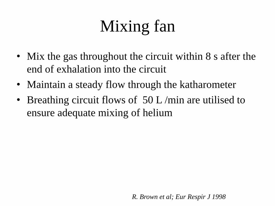
Mixing fan
• Mix the gas throughout the circuit within 8 s after the
end of exhalation into the circuit
• Maintain a steady flow through the katharometer
• Breathing circuit flows of 50 L /min are utilised to
ensure adequate mixing of helium
R. Brown et al; Eur Respir J 1998

CO2 and water absorbers
• CO2 and water to be removed before the sample is introduced into helium analyser
• Soda lime canister is mounted vertically to ensure uniform distribution of the granules for absorbing CO2
• The canister should be changed after every 20 determinations or when the CO2 concentration in the circuit rises above 0.5% to avoid patient discomfort and hyperventilation
• Activity should be ensured before each test
R. Brown et al; Eur Respir J 1998

Helium analyzer
• The helium analyser should have a range of 0–10%
helium, a resolution of ≤ 0.01% helium over the
entire range and a 95% response time of < 15 s to a
2% step change in helium concentration in the
breathing circuit
• Calibrated over the range of O2 concentrations
encountered during measurement of FRC
• Temperature of the gases entering the helium analyser
should be same as that during calibration
R. Brown et al; Eur Respir J 1998

Temperature sensors
• The temperature of gas inside the system differs from
both BTPS and ATPS conditions
– exhaled warm gas
– room temperature
– heat generated by absorption of CO2 in the soda
lime canister
• Temperature of the gas in the breathing circuit should
be measured so that these lung volumes can be
corrected to BTPS conditions
R. Brown et al; Eur Respir J 1998

Dead space
• The breathing valve and mouthpiece should have a
combined dead space of < 100 mL
• The size of this dead space should be available from
the manufacturer or measured by water displacement
R. Brown et al; Eur Respir J 1998

Procedure
• Turned on and allowed an adequate warm-up time (<
10 min)
• Calibration to be done according to manufacturer’s
instructions
• Check list before procedure
– Activity of the CO2 and water absorbers in the
helium meter line
– Water level in case of water-sealed spirometers
– Circuit leaks
R. Brown et al; Eur Respir J 1998
J Wanger et al; Eur Respir J 2005

Procedure
• Patient preparation
– Checked for a perforated eardrum (if so, an earplug should be used)
– Seated comfortably, with no need to remove dentures
– Procedure is explained, emphasising the need to avoid leaks around the mouthpiece during the test andto use a nose clip
R. Brown et al; Eur Respir J 1998
J Wanger et al; Eur Respir J 2005

Procedure
• Circuit is flushed with air
• Oxygen is subsequently added to raise the final
oxygen concentration to about 25-30%
• Helium meter reading adjusted to zero, helium is
added to raise the helium concentration to nearly full
scale deflection (10%) on the analyser
R. Brown et al; Eur Respir J 1998
J Wanger et al; Eur Respir J 2005
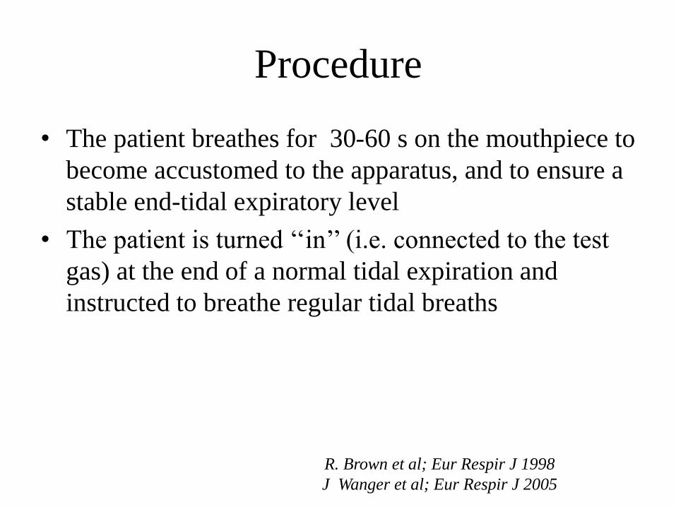
Procedure
• The patient breathes for 30-60 s on the mouthpiece to
become accustomed to the apparatus, and to ensure a
stable end-tidal expiratory level
• The patient is turned ‘‘in’’ (i.e. connected to the test
gas) at the end of a normal tidal expiration and
instructed to breathe regular tidal breaths
R. Brown et al; Eur Respir J 1998
J Wanger et al; Eur Respir J 2005

Procedure
• A constant flow of 100% oxygen is added to the circuit at a rate determined by an estimate of the patient's oxygen consumption. This estimate is usually 3–4 mL/kg/min for adults. The equipment should allow and assure oxygen flows up to 500 mL/min
• Boluses of oxygen can be added as needed (e.g. every 15–30 s) to keep spirometer volume constant at end expiration
• Starts with elevated concentrations of oxygen in the circuit; further oxygen is not added
R. Brown et al; Eur Respir J 1998
J Wanger et al; Eur Respir J 2005

Measurement
• The helium concentration is noted every 15 s and
equilibration is considered to be complete
– Change in helium concentration is < 0.02% for 30
s
– Change in FRC is less than 40 mL per 30 s in
systems that report FRC directly
• Once the helium equilibration is complete, the patient
is turned ‘‘out’’ (i.e. disconnected from the test gas)
of the system
• The test rarely exceeds 10 min, even in patients with
severe gas-exchange abnormalities R. Brown et al; Eur Respir J 1998
J Wanger et al; Eur Respir J 2005

Measurement
• At least one technically satisfactory measurement should be obtained
• Two or more measurements of FRCHe need to be made only when necessitated by clinical or research need due to the extra costs and time in making multiple measurements
• For younger children, at least two technically satisfactory measurements be performed
• In case of multiple measurements, value reported for FRCHe should be the mean of technically acceptable results that agree within 10%
R. Brown et al; Eur Respir J 1998
J Wanger et al; Eur Respir J 2005


Linked ERV f/b IVC
• Mean value of three satisfactory linked in ERV
manoeuvres to be reported
• Factors that lead to unsatisfactory manoeuvres
include cough, glottal closure, gas leak from the nose
or mouth and too brief effort
• Largest of the three satisfactory IVC manoeuvres
should be reported
RV = FRC – ERV
TLC = RV + IVC
R. Brown et al; Eur Respir J 1998
J Wanger et al; Eur Respir J 2005

Linked IC manoeuvre
• In those with severe obstructive dysfunction or severe
dyspnea who are unable to follow the FRC
measurements with a linked ERV manoeuvre
• Separate IVC or EVC manoeuvre can be performed
after the FRC determination
TLC = FRC + IC
RV = TLC - IVC
R. Brown et al; Eur Respir J 1998
J Wanger et al; Eur Respir J 2005

Calculation
Calculation of Vapparatus
• The initial helium concentration (Fsp,He,1) is noted
• An additional 2- 3 L of room air is then added
(measured with a calibrated syringe) and the second
meter reading (Fsp,He,2) noted when it is stable. If
Vsp is the volume of the spirometer prior to this last
addition of air, and Vair the precise volume of air
added during the last step, then:

Calculation
• Fsp,He,3 is the helium concentration at the end of
the determination and Vds is the valve and
mouthpiece dead space

Reproducibility
• Little information is available in the literature to base
reproducibility standards
• Issues in regard to reproducibility
– magnitude of change that is of clinical relevance
– time constraints in busy laboratories
– differences amongst equipment of different
manufacturers
– effect of patient stature, age and disease state
– time required for helium washout to occur between
measurements not knownR. Brown et al; Eur Respir J 1998

Reproducibility
• Number of FRC measurements to be tailored to fit the
reason why the measurements were made
• When accurate readings are needed, mean of two
FRC measurements should be reported
• If values vary by 200 ml, third measurement should
be made and the mean of two closest values reported
• Errors of less than 200 mL in FRC are considered to
be negligible attributed to expected individual
variation
R. Brown et al; Eur Respir J 1998

Loss of Helium / leaks
• Lead to over estimation of FRC
• Continued helium loss leads to failure to achieve
equilibration
– Helium dissolution in the water of the spirometer
– Equipment leaks
– Leaks around the nose clip and mouthpiece
– Transfer through ruptured tympanic membranes
– Swallowing and absorption into the fluids and
tissues of the body
R. Brown et al; Eur Respir J 1998

Loss of Helium / leaks
• The effect of He absorption is a small overestimation
of FRC
• Uncertainty as to the exact magnitude of the
correction and the variability from patient to patient
• No correction be made until better data are available
R. Brown et al; Eur Respir J 1998

Effect of N2 excretion
• Upon rebreathing, a redistribution of gas takes place
with helium moving from spirometer to lung and
nitrogen from lung to spirometer
• This decrease in helium in the spirometer results in a
relative increase of the concentration of nitrogen in
the gas mixture in the spirometer
• Nitrogen excretion must be considerably less because
the alveolar to spirometer gradient for nitrogen is
much smaller
• Correction for nitrogen excretion is not necessary
R. Brown et al; Eur Respir J 1998

Effect of ‘R’
• Ratio of carbon dioxide production (V'CO2) to
oxygen consumption (V'O2)
• Error due to R less than or greater than 1 lead to over
estimation or under estimation of FRC respectively
• Because R is not measured and the effect of it is
negligible, it is recommended that no correction be
made
R. Brown et al; Eur Respir J 1998
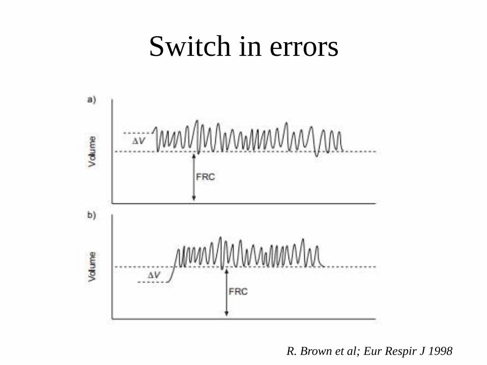
Switch in errors
R. Brown et al; Eur Respir J 1998

Variations in FRC
R. Brown et al; Eur Respir J 1998

Variations in FRC
R. Brown et al; Eur Respir J 1998

Hazards
• Infection may be contracted from improperly cleaned
tubing, mouthpieces, manifolds, valves, and
pneumotachometers
• Hypercapnia and/or hypoxemia may occur as
consequence of failure to adequately remove CO2 or
add O2 to the rebreathed gas
AARC guideline: static lung volumes: 2001 revision &
update

Visual evidence of air trapping
• Encouraging deep inhalation - gas mixing in regions of relatively poor ventilation and to decrease equilibration time
• Following a deep inhalation, however, a patient with severe airways obstruction may take many breaths before returning to the original FRC
• Errors in the amount of oxygen added during the procedure so the practice is not recommended, at least in patients with considerable airways obstruction
Cotes textbook of lung function 6th ed

Visual evidence of air trapping
Cotes textbook of lung function 6th ed

Helium dilution
Advantages Disadvantages
Simple to perform FRC underestimated in sever air
flow obstruction or emphysema
Inexpensive Cant be used in case of
communicable diseases


Comparison with body
plethysmographyStudy Participants Objective Outcome
Schaanning CG et
al
1973
10 normal subjects
10 hyperinflation
Concurrent testing
by HDT &
plethysmography
Comparison
between two
methods
Plethysmography yielded a
higher FRC than HDT, with
a mean difference of 0.3 L
in healthy subjects and 0.5 L
in obstructed patients
(p=0.001)
Andersson et al
1988
82 subjects
I (20): normal PFT
II (23): FEV1 40-
65%
III (20): FEV1 <
40%
IV (19):
emphysema
Comparison
between two
methods
No significant difference of
TLC was seen except in
group of severe obstruction
Claudio Tantucci
et al 2016
20 - obstructive
7 - restrictive
10 - normal
Comparison
between HDT,
body
plethysmogra
phy and
radiographic
Both radiograph &
plethysmography provide
similar values of TLC.
He dilution method
measures lower TLC in
patients with airflow
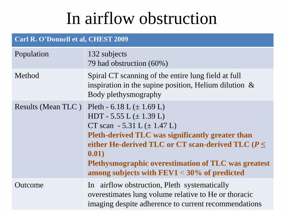
In airflow obstructionCarl R. O’Donnell et al, CHEST 2009
Population 132 subjects
79 had obstruction (60%)
Method Spiral CT scanning of the entire lung field at full
inspiration in the supine position, Helium dilution &
Body plethysmography
Results (Mean TLC ) Pleth - 6.18 L (± 1.69 L)
HDT - 5.55 L (± 1.39 L)
CT scan - 5.31 L (± 1.47 L)
Pleth-derived TLC was significantly greater than
either He-derived TLC or CT scan-derived TLC (P ≤
0.01)
Plethysmographic overestimation of TLC was greatest
among subjects with FEV1 < 30% of predicted
Outcome In airflow obstruction, Pleth systematically
overestimates lung volume relative to He or thoracic
imaging despite adherence to current recommendations

Comparison with body
plethysmography
• The difference is attributed to
– air spaces in the lung which do not communicate
with the central airways during quiet breathing
– due to trapped gas which increases with
exacerbations of a reversible bronchial obstruction
– mouth pressure does not reflect the intrapulmonary
pressure variations during rapid compression and
decompression manoeuvres in plethysmography
in cases of airway obstruction

Single breath tests
• Performed almost exclusively in conjunction with the determination of the transfer factor of the lung for CO
• Underestimates the true lung volume in subjects with airflow limitation
• Not recommended for routine use, unless in connection with the determination of the effective TL.CO when screening large numbers of subjects

He dilution in mechanically ventilated
• An increase in FRC is the goal of therapy with
positive end-expiratory pressure (PEEP) in ARDS
• Useful in determining the efficacy of a particular
level of PEEP
• Allows reliable, simple, and reproducible
measurements of lung volume in mechanically
ventilated ALI/ARDS patients
Gregory P. Heldt et al, CHEST 1978

He dilution in mechanically ventilated
Gregory P. Heldt et al, CHEST 1978

He dilution in mechanically ventilated
• In the non rebreathing position, the patient’s airway is attached to the outlet side of the spool valve. The ventilator is attached to the inlet side of the valve
• During rebreathing position, the airway is connected to the bag, and the inspiratory volume of the ventilator is pushed into the plastic box, emptying the bag into the patient’s lungs
• The pressurized gas in the box escapes through the ventilator during the expiratory cycle, and the patient simultaneously exhales into the rebreathing bag
• Thus, by a simple switching of the valve, the ventilator can be changed from directly ventilating the patient to compressing the rebreathing bag
Gregory P. Heldt et al, CHEST 1978
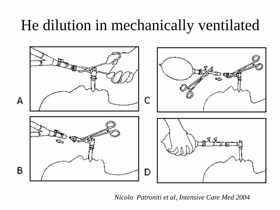
He dilution in mechanically ventilated
Nicolo Patroniti et al, Intensive Care Med 2004

He dilution in mechanically ventilated
• Good correlation was found EELV measured
by CT scan in 21 mechanically ventilated
ARDS patients
• Practical alternative to EELVCT
Nicolo Patroniti et al, Intensive Care Med 2004
Take home message
• Simple method to measure FRC
• Underestimates FRC in cases of airway
obstruction
• Difference of FRC b/n HDT and body
plethysmograph quantify non ventilated lung
and trapped air
• HDT can also used for EELV measurement in
critically ill

Thank you