hellan strainer benefits 1 quality assurance and product ... · pdf filehellan strainer...
TRANSCRIPT

TABLE OF CONTENTS
CLEVELAND, OHIO USAPHONE (216) 206-4200 • FAX (216) 206-4242
PAGE
Hellan Strainer Benefits 1
Quality Assurance and Product Testing 2
Codes and Standards Compliance 3
Typical Applications 4-5
Unique Operating Features 6-7
Strainer Types 8-10
Selecting a Strainer 11-12
Screen Options 11 & 13
Component Material 14-16
Standard Flow Rates and Pressure Ratings 17
Automatic Operation Options 18-19
External Scraper Adjustment 20
Pressure Switch and Three Way Ball Valve 21
Flow Rate vs Pressure Drop 22
Dimensional Information 23-53
Typical Pressure Drop vs Flow Rate Curves 54-79
Model Number Specification 80-81
Samples of Standard Specification 82

1
BENEFITS OF THE HELLAN STRAINER
CLEVELAND, OHIO USAPHONE (216) 206-4200 • FAX (216) 206-4242
REMOVE SOLIDS WITHOUT STOPPING THE FLOW
Instead of trapping solids in a basket which must then beremoved for frequent clean-outs, the Hellan Strainer removessolids from the fluid flow without stopping the flow or disas-sembling the strainer. A simple turn of the hand wheel (oractuation of the screen motor in automatic units) rotates thescreen against a scraper bar. Debris moves to a sump areawhere it is removed by periodic flushing.
LOW OPERATING COSTS
Removing solids from the screen takes about thirty seconds,compared to one or two hours for a basket strainer. Laborcosts can be completely eliminated with our automatic self-cleaning strainer.
SAFETY FOR EMPLOYEE PERSONNEL
The Hellan Strainer closed system protects personnel from contact with strained debris that may include contaminants orhazardous materials.
HIGH QUALITY CONSTRUCTION
Hellan Strainers are designed and built to ANSI/ASQCStandard Q94-1987. Each strainer is proof pressure tested to150% MAWP, per ASME standards, before shipment. QualityAssurance and manufacturing systems are registered for compliance with ISO-9001 International Standard.
MEET OR EXCEED MAJOR CE/PED, AND INTERNATIONAL STANDARDS
Hellan Strainers are available in models that comply with major U.S. industrial codes and standards, includingASME, the American Bureau of Shipping, Lloyd’s Register, and CE/PED. Select models are listed with UnderwritersLaboratories. Models are also available in compliance withmajor international standards, including D.I.N., I.E.C. andCenelec specifications.
MATERIAL OF CONSTRUCTION FOR A VARIETYOF APPLICATIONS
Hellan Strainer bodies are available in cast iron, cast steel, cast stainless steel, bronze and custom materials such as SuperDuplex to meet the demands of a wide range of applications.
LOW MAINTENANCE COSTS
While there is no routine disassembly needed with a HellanStrainer, all of the internal components can be changed without any special tools. Servicing or parts replacement istherefore very inexpensive.
LOW INSTALLATION COSTS
A Hellan Strainer weighs about half as much as comparableconventional basket-type strainers and requires about 60% of the space. It may be mounted in-pipeline, in a vertical orhorizontal position. No special foundation is needed andinstallation is simple and less costly.
MANUAL OR AUTOMATIC OPERATION
Hellan Strainers are available in manual or automatic models.A full array of controls is available for remote, automatedoperation of automatic models. Manual models can beupgraded to automatic operation in the field without disruption of the fluid handling system.
LOW CAPITAL INVESTMENT
Hellan Strainers are competitively priced.

QUALITY ASSURANCE AND PRODUCT TESTING
CLEVELAND, OHIO USAPHONE (216) 206-4200 • FAX (216) 206-4242
2
Hellan Strainers are designed and manufactured under a stringent Total Quality Management Program. This TQM pro-gram and a continuous improvement policy keep our qualitystandards and procedures among the highest in the industry.Designed to ISO 9001, our quality program directs all aspects ofour business, including procurement, design, manufacturing,inspection and testing.
Every Hellan Strainer is designed and built to ANSI/ASQCStandard Q94-1997. Prior to shipment, each strainer is proofpressure tested to 150% MAWP, per ASME standards.
Our commitment to quality and the unique operating featuresof our strainer design assure our customers that HellanStrainers will provide consistent performance in even the mostchallenging applications.

3
STANDARDS, CERTIFICATION AND PATENTS
CLEVELAND, OHIO USAPHONE (216) 206-4200 • FAX (216) 206-4242
Hellan Strainers are available in models that comply withmajor U.S. and international standards, including those ofthe following organizations:
American Society of Mechanical Engineers (ASME)Hellan Strainers are designed and manufac-tured in accordance with ASME Boiler andPressure Vessel Code, Section VIII, Division 1. All strainers are proof pressuretested at 150% of their recommended maximum allowable operating pressure.
American Bureau of ShippingMost Hellan Strainers appearing in this catalog have been type approved for service infuel oil, lube oil, fresh water and sea water serv-ice by the American Bureau of Shipping. ABShas rated Hellan Strainers for 150 PSI (10.34 bars) MAWP to 450 PSI (31.03 bars)MAWP, depending on flange class, con structionmaterial and temperature of the process fluid.
CE CertifiedNon automatic strainers cast in steel or stain-less steel pipe sizes 4"-12" can be CE certifiedto Pressure Equipment Directive PED97/23/EC if requested.
ISO-9001Quality systems certified by DNV-GL toISO-9001 International Standard. CertificateNo. 09458.
American Iron and Steel (AIS)The Hellan Strainer Co is pleased to supplyproducts that are in compliance with theConsolidated Appropriations Act of 2014(Public Law 113-76) “American Iron andSteel (AIS)”
International StandardsHellan Strainers are available in models that comply with most international standards, including D.I.N., I.E.C. andCenelec specifications.
Underwriters LaboratoriesNon-automatic Hellan Strainers constructedof cast iron, cast steel, bronze or cast stainlesssteel in pipe sizes from 2" through 14" withscreen perforations of 3/32", 1/8" or 3/16" are listed with Underwriters Laboratories(Re-exami nation service) and are UL listedunder Strainers, Pipe Line (HLCV), File EX 1708(N), “Fire Main Pipe Strainer.”
NSF MarkThe NSF mark assures consumers, retailersand regulators that products have been rigorously tested to comply with all standardrequirements. Contact factory for certifiedsizes and materials.
Lloyd’s RegisterHellan Strainers are Type Approved byLloyd’s Register and have met their requirements for use in fresh and salt watersystems (including fire main), fuel oil systems and lubricating oil systems.Certificate No. 01/60001
Hellan Strainers TR CU CertificatesHellan Strainers, in both manual and auto-matic types, are certified to Russian TR CUstandards. (Formerly GOST-R standards)
Conflict MineralsSection 1502 of the US law known as the“Dodd-Frank Act” includes a requirementthat companies using gold, tin, tungstenand tantalum make efforts to determine ifthose materials came from the DemocraticRepublic of Congo (DRC) or an adjoiningcountry and, if so, to carry out a “due diligence” review of their supply chain todetermine whether their mineral purchasesare funding armed groups in eastern DRC.
Patent ProtectionHellan Strainers are protected by several U.S. patents. Design applications on file for new patent protection.
R

APPLICATIONS
CLEVELAND, OHIO USAPHONE (216) 206-4200 • FAX (216) 206-4242
4
MARINE
Hellan Strainers are used on U.S. Navy ships in sea water cooling of electronic equipment (i.e., sonar, radar, close inweapon systems, etc.), lube oil, firemain systems, and fuel filtration.
PETROLEUM
Hellan Strainers are used on offshore rigs and FPSOs in filtration systems, deluge fire protection systems, protection of plate and frame heat exchangers and other applications.
PETROCHEMICAL
Hellan Strainers protect plant equipment (i.e., condensers,spray nozzles, heat exchangers, pumps, etc.) strain coolingtower water, remove polyethylene fines from process water and are used in deluge fire protection systems.

5
APPLICATIONS
CLEVELAND, OHIO USAPHONE (216) 206-4200 • FAX (216) 206-4242
FIRE PROTECTION
Hellan Strainers are U.L. approved for spray nozzle protectionin all types of fire protection systems.
WASTE WATER TREATMENT
Hellan Strainers are used in belt filter presses for protection ofspray nozzles and in secondary effluent systems for protectionof chlorinators, seal water, plant service and foam control.
ETHANOL PLANT
Hellan Strainers are used to protect plate and frame heatexchangers downstream of the slurry tank. Used to capturecorn slurry from caustic solution during cleaning of the slurry tank.
POWER UTILITY PLANTS (FOSSIL, HYDRO & NUCLEAR)Hellan Strainers remove zebra mussels, sand, grit, small fish,etc., from lakes and rivers for protection of plant equipment.Strains water for turbine bearings.
IRON AND STEEL FACILITIES
Hellan Strainers are used in recirculating water, descaling water and cooling water for hot strip and plate mills, blast furnaces, open hearths and continuous casting mills.
IRRIGATION SYSTEMS
Hellan Strainers are used in irrigation systems, including golfcourses, to protect spray nozzles by removing debris fromlakes, rivers and ponds.

UNIQUE OPERATING FEATURES
CLEVELAND, OHIO USAPHONE (216) 206-4200 • FAX (216) 206-4242
6
THE HELLAN STRAINER DESIGN PROVIDES SOLIDSREMOVAL WITHOUT INTERRUPTING THE FLUID FLOW
Instead of trapping solids in a basket which then must beremoved for frequent clean-outs, the Hellan Strainer removesthe solids from fluid without stopping the flow or disassembling the strainer. The sequence of operation is illustrated below.
¶ Fluid passes into the strainer and through a screen.
• A deflection rib protects the screen from large objects.
‚ The screened fluid flows out of the strainer and into service.
„ Rotating the screen, by either handwheel or motor,moves the outer screen surface against a scraper bar. The scraper bar removes collected debris from thescreen’s outer surface.
” Debris moves to the sump area of the strainer where it isremoved by periodic flushing.
SPECIAL FEATURES PROVIDE CONVENIENCEAND HIGH PERFORMANCE.» External scraper adjustment, if supplied.
… O-rings at the screen cover plate and shaft provide atight seal while allowing operation at low torque.
‰ Backwash system is available to remove debris from screen on low pressure applications except 2", 2-1/2" and 3" angle types and 3" D-type.
� Eductor is available at discharge for low-pressure applications.
¿ Brush can replace solid scraper on all but 2" and 2-1/2"Angle-type and 2-1/2" and 3" D-type.
OPERATING FEATURES THAT PROVIDE REAL BENEFITS
• Eliminate downtime for solids removalThe Hellan Strainer allows users to eliminate solids anddebris from fluids without stopping the flow of the fluid.Processes requiring the fluid continue uninterrupted.
• Employees are not exposed to possible contaminatesDebris that may include contaminates and hazardousmaterials is removed from the fluid flow without disas-sembly of the strainer. Maintenance personnel and otheremployees do not come into contact with this debris.
• Minimum labor requirements for solids removalThe Hellan Strainer reduces the time required to removesolids from the fluid flow. Manually-operated modelsrequire only a periodic turning of the handwheel toremove solids. Labor and cleaning time is usually lessthan 30 seconds. Labor requirements can be completelyeliminated with automatic strainers that can be con-trolled by timers and/or pressure differential switches.
…
”
»
•
‚„
TO DRAIN

7
UNIQUE OPERATING FEATURESWDA Type
CLEVELAND, OHIO USAPHONE (216) 206-4200 • FAX (216) 206-4242
¶ Fluid passes into the strainer and thru the screens.
• The screened fluid flows out of the strainer.
‚ Rotating the screen, by motor, moves the outer screen surface against the scraper bar. The scraper bar dislodges and removes collected debris from the screen’s outer surface.
„ While the screen is rotating, the drain is opened and the debris is forced out through the drain in use.
” A drain separator is used to prevent the fluid velocity from pulling the debris away from the drain tube opening.
» Large inspection ports, sealed with O-rings, permit easy,external adjustment of the scraper bars and drain separators.
…O-rings at the screen shaft provide a tight seal while allowing operation at low torque.
…
”»
•
‚
„
„
„

STRAINER TYPES
CLEVELAND, OHIO USAPHONE (216) 206-4200 • FAX (216) 206-4242
8
➧
➧
➧
➧
INLINE FLOW BODY-SINGLE SCREEN
• Inline Flow, Manual Strainers (Type TSH) (Single ManualRotating Screen) (Sizes 1-1/2", 2", 2-1/2", 3") Type TSHHellan Strainers employ a single handwheel equipped rotatingscreen and a rigid scraper bar to remove solids from the sur-face of the screen when the handwheel is rotated. A solids col-lecting sump is also provided. Cleaning of the Type TSH isaccomplished by opening a valve on the sump flush connec-tion and rotating the handwheel several times. For best results,the cleaning cycle should be performed when the strainer isunder a positive pressure. An eductor and/or backwash mayaid in debris removal in low-pressure applications. Type TSHmust be installed in horizontal flow position as illustrated.
• Inline Flow, Automatic Strainers (Type TSA) (SingleMotorized Rotating Screen) (Sizes 1-1/2", 2", 2-1/2", 3") TypeTSA Hellan Strainers employ a single, electric motor-drivenrotating screen and a rigid scraper bar to remove solids from thesurface of the screen when the screen is rotated. A solids collect-ing sump is also pro vided. Cleaning of the Type TSA is initiatedwhen the motor and flush valve operator are actuated. Controlsto accomplish these electrical functions are provided. For bestresults, the cleaning cycle should be performed when the strain-er is under a positive pressure. An eductor and/or backwash mayaid in debris removal in low-pressure applications. Type TSAmust be installed in horizontal flow position as illustrated.
ANGLED FLOW BODY-SINGLE SCREEN
• Angled Flow, Manual Strainers (Type AH) (Single ManualRotating Screen) (Sizes 2", 2-1/2", 3") Type AH HellanStrainers employ a single hand-wheel equipped rotating screenand a rigid scraper bar to remove solids from the surface of thescreen when the handwheel is rotated. A solids collecting sumpis also provided. Cleaning of the Type AH is accomplished byopening a valve on the sump flush connection and rotating thehandwheel several times. For best results, the cleaning cycleshould be performed when the strainer is under a positivepressure. An eductor and/or backwash may aid in debrisremoval in low-pressure applications. Type AH must beinstalled in vertical down-flow position as illustrated.
• Angled Flow, Automatic Strainers (Type AA) (SingleMotorized Rotating Screen) (Size 3" Only) Type AA HellanStrainers employ a single, electric motor-drive rotating screenand a rigid scraper bar to remove solids from the surface of thescreen when the screen is rotated. A solids collecting sump isalso provided. Cleaning of the Type AA is initiated when themotor and the flush valve operator are actuated. Controls toaccomplish these electrical functions are provided. For bestresults, the cleaning cycle should be performed when the strain-er is under a positive pressure. An eductor and/or backwash mayaid in debris removal in low-pressure applications. Type AAmust be installed in vertical down-flow position as illustrated.

9
STRAINER TYPESContinued
CLEVELAND, OHIO USAPHONE (216) 206-4200 • FAX (216) 206-4242
INLINE FLOW BODY-TWO SCREENS
• Inline Flow, Manual Strainers (Type DH) (Two ManualRotating Screens) (Sizes 2-1/2", 3", 4", 6", 8", 10", 12")Type DH Hellan Strainers employ two handwheel-equippedrotating screens and rigid scraper bars to remove solids fromthe surface of the screens when the handwheels are rotated.A solids-collecting sump is also provided. Cleaning of theType DH strainer is accomplished by opening a valve on the sump flush connection and rotating the handwheels several times. For best results, the cleaning cycle should beperformed when the strainer is under a positive pressure. An eductor and/or backwash may aid in debris removal in low-pressure applications. Type DH can be installed invertical up-flow or horizontal flow position (with the draindischarging downward).
• Inline Flow, Automatic Strainers (Type DA) (Two Motor -ized Rotating Screens) (Sizes 4", 6", 8", 10", 12") Type DAHellan Strainers employ two electric motor-driven rotatingscreens and rigid scraper bars to remove solids from the surface of the screens when the screens are rotated. A solids-collecting sump is also provided. Cleaning of the Type DAstrainer is initiated when the motors and the flush valveoperator are actuated. Controls to accomplish these electricalfunctions are provided. For best results, the cleaning cycleshould be performed when the strainer is under a positivepressure. An eductor and/or backwash may aid in debrisremoval in low-pressure applications. Type DA can beinstalled in vertical up-flow or horizontal flow position(with the drain discharging downward).
INLINE FLOW BODY-ONE SCREEN
• Inline Flow, Automatic Strainers (Type WDA) (Two Motor -ized Rotating Screens) (Sizes 20", 24", 30") and (Type WSA)(One Motorized Rotating Screen) (Sizes 14" and 16") TheseHellan Strainers employ one or two electric motor-drivenrotating screens and rigid scraper bars to remove solids fromthe surface of the screens when the screens are rotated. Asolids collecting sump is also provided. Cleaning of thestrainer is initiated when the motors and the flush valveoperator are actuated. Controls to accomplish these electricalfunctions are provided. For best results, the cleaning cycleshould be performed when the strainer is under a positivepressure. An eductor and/or backwash may aid in debrisremoval in low-pressure applications. Type WDA and Type WSA must be installed in horizontal flow position asillustrated. Handwheel may be substituted for motorizeddrive but screen may be difficult to rotate.
10.0
5.0
15.0
20.0
25.0PSID
NAMEPLATE

STRAINER TYPESContinued
CLEVELAND, OHIO USAPHONE (216) 206-4200 • FAX (216) 206-4242
10
INLINE FLOW BODY-FOUR SCREENS
• Inline Flow, Manual Strainers (Type QH) (Four RotatingScreens) (Sizes 14" and 16") Type QH Hellan Strainers employfour handwheel-equipped rotating screens and rigid scraperbars to remove solids from the surface of the screens when thehandwheels are rotated. A solids-collecting sump is also provid-ed. Cleaning of the Type QH strainer is accomplished by open-ing one or both valves on the two sump flush outlets and rotat-ing the handwheels several times. For best results, the cleaningcycle should be performed when the strainer is under a positivepressure. An eductor and/or backwash may aid in debrisremoval in low-pressure applications. Type QH must beinstalled in vertical up-flow position as illustrated.
• Inline Flow, Automatic Strainers (Type QA) (Four Motor izedRotating Screens) (Sizes 14" and 16") Type QA HellanStrainers employ four motor-driven rotating screens andrigid scraper bars to remove solids from the surface of thescreens when the motor-driven screens are rotated. A solids-collecting sump is also provided and equipped with twoelectrically-operated flush valves. Cleaning of the Type QAstrainer is initiated when the screen drive motors and flushvalve operators are actuated. Controls to accomplish theseelectrical functions are required. For best results, the clean-ing cycle should be performed when the strainer is under apositive pressure. An eductor and/or backwash may aid indebris removal in low-pressure applications. Type QA mustbe installed in vertical up-flow position as illustrated.
INLINE FLOW BODY-SIX SCREENS
• Inline Flow, Manual Strainers (Type HH) (Six RotatingScreens) (Size 20" only) Type HH Hellan Strainers employ six handwheel-equipped rotating screens and rigid scraperbars to remove solids from the surface of the screens when the handwheels are rotated. A solids-collecting sump is alsoprovided. Cleaning of the Type HH strainer is accomplishedby opening the valves on the two sump flush outlets and rotating the handwheels several times. For best results, thecleaning cycle should be performed when the strainer is undera positive pressure. An eductor and/or backwash may aid indebris removal in low-pressure applications. Type HH must be installed in vertical up-flow position as illustrated.
• Inline Flow, Automatic Strainers (Type HA) (Six Motor izedRotating Screens) (Size 20"only) Type HA Hellan Strainersemploy six motor driven rotating screens and rigid scraperbars to remove solids from the surface of the screens whenthe motor-driven screens are rotated. A solids-collectingsump is also provided and equipped with two electrically-operated flush valves. Cleaning of the Type HA strainer isinitiated when the screen drive motors and flush valveoperators are actuated. Controls to accomplish theseelectrical functions are provided. For best results, thecleaning cycle should be performed when the strainer isunder a positive pressure. An eductor and/or backwash mayaid in debris removal in low-pressure applications. Type HAmust be installed in vertical up-flow position as illustrated.
15.010.0
25.0
20.05.0
PSID
10.0 15.0
25.0
20.05.0
PSID

11
HOW TO SELECT A HELLAN STRAINER
CLEVELAND, OHIO USAPHONE (216) 206-4200 • FAX (216) 206-4242
There are eight application requirements that should beaddressed when selecting a specific Hellan Strainer model.Here are the considerations and options available for each requirement:
1 PERFORATION SIZE OF THE SCREENS
Hellan recommends that a screen perforation hole diameter be selected that is 40% to 60% of the diameter of the smallestorifice in the system. Selecting a smaller perforation thanrequired leads to unnecessary cleaning cycles and higher pressure drops during operation.
2 SIZE OF THE STRAINER
A) Existing Pipe Size MethodThis method is used when a Hellan Strainer is installed inan existing network of piping. Flow rate and the intendedpressure drop are within the application requirements.
In these situations, it is common practice to select a strainersize that matches the existing pipe size, i.e., an 8" strainerwould be selected for an installation with an existing 8" line.
B) Flow Rate Requirement Versus Pressure Drop MethodThis method should be utilized when selecting a strainer fora new application, or as a replacement strainer in existingsystems where a specific flow rate needs to be maintained.
Refer to the chart at right for flow rates of available strainersizes. Refer to the pressure drop versus flow rate charts forvarious size strainers, appearing on page 22.
C) High Concentration of SolidsFor removal of debris greater than 100 PPM, a solidseparator is recommended upstream of the Hellan strainer.
SCREEN OPTIONS
Perforated Screens Wedge-Wire Screens Round Opening Size Slot Width
Fractional Decimal Metric Mesh Micron Inches Metric Mesh Micron
1/4" .250" 6.35 mm 3 6350 .015" 0.38 mm 40 385
3/16" .188" 4.77 mm 4 4750 .009" 0.23 mm 60 230
1/8" .125" 3.18 mm 6 3175 .007" 0.18 mm 80 180
3/32" .094" 2.38 mm 8 2450 *.005" 0.13 mm 100 140
1/16" .063" 1.59 mm 12 1588 *.004" 0.10 mm 150 100
1/32" .031" 0.79 mm 24 794Other perforated screen opening sizes and Wedge-Wire screen slot widths
are available upon request. See page 13 for complete information on screens.
*Consult factory for these applications .
STRAINER SIZE OPTIONS
Pipe Size Flow Pressure/flow Inches mm GPM* Liter/min.* data
1-1/2" 38 95 360
2" 51 95 360
2-1/2" 64 160 606
3" 76 235 890
4" 102 360 1363
6" 152 880 3331
8" 203 1450 5489 See Page 22
10" 254 2075 7855
12" 305 2750 10410
14" 356 4100 15520
16" 406 5300 20063
20" 508 8250 31230
24" 610 10650 40315
30" 762 16650 63027
*1.5 psid with clean 1/8" perforated screen.
D) Discharge Side of Pump It is recommended that a Hellan strainer be installed on the discharge side of a centrifugal pump with a minimumoperating pressure of 30 PSIG or 2 BAR. If operatingpressure is less, please contact the Hellan sales departmentfor assistance.
3 STRAINER CONSTRUCTION MATERIALS
Hellan Strainers are available with cast bodies constructed in iron, steel, stainless, and bronze or fabricated in steel and stainless steel. Other materials such as Super Duplex are available by special order. The material used for internal components depends on the material of the body.
The selection of a body material depends on three criteria:
A) The operating pressure of the systemThe body material selected should have a pressure ratingthat is appropriate for the operating pressure of the system.(See page 17 for maximum pressure ratings for strainers ofvarious materials and flange types.)
B) The fluid to be strainedStandard cast iron models are commonly used for freshwater applications, while other materials are used to meetspecial needs: cast stainless steel for highly corrosive fluids,and bronze or monel for seawater applications.
C) The environment in which the strainer operatesA longer service life may be attained by specifying a construction material that is appropriate for the serviceenvironment. Stainless steel should be considered for highlycorrosive environments and bronze for marine or otherapplications where salt air is present.

HOW TO SELECT A HELLAN STRAINERContinued
CLEVELAND, OHIO USAPHONE (216) 206-4200 • FAX (216) 206-4242
12
4 FLANGE REQUIREMENT
Strainers of cast iron construction are normally furnished with integral flanges that have dimensions in accordance with ANSIB16.1, class 125 or class 250. Strainers of cast steel or caststainless steel are normally furnished with integral flanges thathave dimensions in accordance with ANSI B16.5, class 150 or class 300. Strainers of bronze construction are normally furnished with integral flanges that have dimensions in accor-dance with ASNI B16.24, class 150 or class 300.
Fabricated steel strainers are available with integral flanges inaccordance with ANSI B16.5 class 150 in 14" through 24" sizes.
Fabricated 30" strainers are provided with ANSI B16.47 class125-LW flanges.
TSH/TSA strainers with NPT connections are also available incast iron, cast steel or cast stainless steel body construction.
Special flanges to accommodate the bolting dimensions ofD.I.N. and other standards are also available.
Flange types should be selected using two considerations:
A) The flange on the strainer must match the mating flangeto which it is being attached.
B) The flange on the strainer should be appropriate for the system pressure.
(See page 17 for information on flanges and pressure ratings.)
5 BODY STYLE REQUIREMENTS
Hellan Strainers are available in angled flow and inline flowbody styles.
Angled flow body styles are available in 2", 2-1/2" and 3" sizes only.
Inline flow body styles are available in 1-1/2", 2", 2-1/2", 3", 4",6", 8", 10", 12", 14", 16", 20", 24", and 30" sizes.
Additional strainer sizes and body styles are available and arecustom designed. Consult the factory for more information.
6 COATINGS
The standard external paint for cast iron and cast steel bodystrainers is Kem Aqua 70P.
The standard external paint for fabricated steel strainers isDevcon 253.
Additional coatings are available; consult the factory for details.
7 METHOD OF OPERATION
Hellan Strainers are available with two methods of operation:
A) Manual operation utilizing a hand wheelB) Automatic operation for utilizing motorized screens
Automatic operation normally utilizes a pressure differentialswitch, automatic discharge valve and a control panel. A separate model number for the control panel must also bespecified. (See pages 18 and 19 for information on automaticstrainers and control panel options.)
8 AFTER YOU HAVE SELECTED A HELLAN STRAINER
After you have reviewed the above considerations and haveselected a Hellan Strainer for your particular application, wesuggest two additional steps be taken before ordering:
A) Check dimensional compatibilityOnce a Hellan Strainer model has been selected, the dimen-sions for the model be reviewed to make sure that appropriateclearances are available in the system design to accommodatethe dimensions of the strainer.
Dimensional information for Hellan Strainer modelsappears on pages 23 through 53.
B) Specifying a model numberA model number for the selected strainer may be specifiedby referring to the model number guide on pages 80 and81. Remember that, when specifying an automatic strainer,a separate model number for the control panel must also be specified.
Please contact the factory at 888-4-HELLAN for assistance.

13
SCREEN OPTIONS
CLEVELAND, OHIO USAPHONE (216) 206-4200 • FAX (216) 206-4242
Hellan Strainers are available with screens manufacturedfrom either perforated metal or wedge-wire materials.Information for standard perforated metal screen optionsand wedge-wire screen options are illustrated below.
STANDARD PERFORATED METAL SCREEN OPTIONS
1/32" Staggered(0.965 mm)16% open
1/16" Staggered(1.588mm)24% open
3/32" Staggered(2.381mm)33% open
Note: Other perforated screen sizes are available on specialorder. Please contact the factory for more information.Open area percentage shown for 1/16" & 1/32" above arefor double wrap over 1/4".
1/8" Staggered(3.175mm)40% open
3/16" Staggered(4.763mm)51% open
1/4" Staggered(6.350mm)58% open
STANDARD WEDGE-WIRE SCREEN OPTIONS
Note: Other wedge-wire slot width sizes are available on specialorder. Please contact the factory for more information.
Wedge-wire slots can be made to order. Standard slotsare listed below:
.015 27% open
.009 18% open
.007 15% open
.005 11% open*
.004 9% open**Consult factory

COMPONENT MATERIALS
CLEVELAND, OHIO USAPHONE (216) 206-4200 • FAX (216) 206-4242
14
STRAINER MATERIAL TYPE 7
Components Cast Iron Welded Steel Cast Steel Cast Stainless Steel Cast Bronze1 Body Cast Iron Carbon Steel Cast Steel Cast Stainless Steel Bronze
ASTM A278 Class 30 ASTM A36 ASTM A216 WCB ASTM A351 CF8M C-95800Screen Bushing N/A Bronze Bronze Bronze N/A
2 Inspection Cover Cast iron Carbon Steel Carbon Steel Cast Stainless Steel BronzeASTM A278 Class 30 ASTM A29 1018 ASTM A351 CF8M C-95800
3 Scraper Blade5 Manganese Bronze 316 Stainless Steel Manganese Bronze 316 Stainless Steel Cast MonelASTM A494 Grade M35-1
4 Clamp Bar5 Red Brass 316 Stainless Steel Red Brass 316 Stainless Steel Cast MonelASTM A494 Grade M35-1
5 Screen Plate Cast Iron Carbon Steel Cast Steel Cast Stainless Steel BronzeASTM A278 Class 30 ASTM A216 WCB ASTM A351 CF8M4 C-95800
6 Shaft Plate Carbon Steel Carbon Steel Carbon Steel 316 Stainless Steel BronzeC-93800
7 Hand Wheel Cast Iron N/A Cast Iron Cast Iron BronzeZinc Plated ASTM B61
8 Shaft 316 Stainless Steel 316 Stainless Steel 316 Stainless Steel 316 Stainless Steel Monel 400UNS N04400
9 Screen1 316 Stainless Steel 316 Stainless Steel 316 Stainless Steel 316 Stainless Steel Monel 400UNS N04400
10 Drain Separator N/A 316 Stainless Steel N/A N/A N/A11 Drain Tube N/A 316 Stainless Steel N/A N/A N/A12 3-way Ball Valve4 316 Stainless Steel 316 Stainless Steel 316 Stainless Steel 316 Stainless Steel 316 Stainless Steel13 Deflector2 316 Stainless Steel N/A Carbon Steel 316 Stainless Steel Monel 400
UNS N0440014 Apron2 316 Stainless Steel N/A 316 Stainless Steel 316 Stainless Steel Monel 400
UNS N0440015 Wetted Fasteners 316 Stainless Steel 316 Stainless Steel 316 Stainless Steel 316 Stainless Steel Monel 400
UNS N0440016 External Fasteners Medium Carbon Steel 316 Stainless Steel Medium Carbon Steel 316 Stainless Steel Monel 400
UNS N0440017 O-Rings Nitrile (Buna N) Nitrile (Buna N) Nitrile (Buna N) Viton Viton18 Keys 316 Stainless Steel 316 Stainless Steel 316 Stainless Steel 316 Stainless Steel Monel 400
UNS N0440019 Collar 303 Stainless Steel 303 Stainless Steel 303 Stainless Steel 303 Stainless Steel 303 Stainless Steel20 Washer Sintered Bronze Sintered Bronze Sintered Bronze Sintered Bronze Sintered Bronze21 Motorized Drive4 Cast Iron Cast Iron Cast Iron Cast Iron Bronze
(Housing Adapter) ASTM A278 Class 30 ASTM A278 Class 30 ASTM A278 Class 30 ASTM A278 Class 30 C-9380022 Motorized Valve Body4 Cast 316 Stainless Cast 316 Stainless Cast 316 Stainless Cast 316 Stainless Bronze
Ball and Stem Stainless Steel Stainless Steel Stainless Steel Stainless Steel BronzePacking and Seat PTFE PTFE PTFE PTFE PTFE
23 Swage Nipple4 Carbon Steel N/A Carbon Steel Stainless Steel Monel 400ASTM A234 ASTM A234 T-304 ASTM B61
24 Pressure Switch4 316 L Stainless 316 L Stainless 316 L Stainless 316 L Stainless 316 L StainlessDiaphragm Viton Viton Viton Viton VitonSeals Viton Viton Viton Viton Viton
25 External Fittings5 316 Stainless Steel 316 Stainless Steel 316 Stainless Steel 316 Stainless Steel Monel 400UNS N04400
26 External Tubing 316 Stainless Steel 316 Stainless Steel 316 Stainless Steel 316 Stainless Steel Monel 400UNS N04400
27 Lubricant3 Mobil Grease XHP 200 Mobil Grease XHP 200 Mobil Grease XHP 200 Mobil Grease XHP 200 Mobil Grease XHP 20028 External Paint7 Kem Aqua 70P Devcon 253 Kem Aqua 70P N/A N/A
Notes: 1) Comprise a welded assembly.2) Deflector and apron are only in 14", 16" and 20" strainers.3) Lubricant is applied to threaded fasteners, thrust washers and press fit parts.4) Motorized components are used only on automatic strainers.
5) Strainers in sizes of 2"and 2-1/2" with single screens and 2-1/2" and 3" with dual screenshave scraper blades integral with the body and do not use clamp bars.
6) Other coatings, such as epoxy, fuse coat epoxy and other special coatings are availableupon request.
7) Body and component materials, other than those listed above, are available upon request.

15
COMPONENT MATERIALS
CLEVELAND, OHIO USAPHONE (216) 206-4200 • FAX (216) 206-4242
The following drawings and chart list the standard com-ponent materials of construction for Hellan Strainers ofvarious body materials.
~
1314
2121
2223
24
12
26
25
1
16
2
34
517
6
DUAL SCREEN CONFIGURATION2-1/2" THRU 12"
4 SCREEN CONFIGURATION14" AND 16" SIZE ONLY
SINGLE SCREEN CONFIGURATION1-1/2" THRU 3"CAN BE AUTOMATIC
ADAPTERGEARBOX
AUTOMATIC CONFIGURATION ONLY
17
7
81920
9
15
18
LC
78
165
24
91
317
1518
1920
6
17
The materials listed may change without notice and do notapply to non-standard strainers.

COMPONENT MATERIALS
CLEVELAND, OHIO USAPHONE (216) 206-4200 • FAX (216) 206-4242
16
BB
WELDED BODY CONSTRUCTION
14" AND 16" (SINGLE DRIVE AND DRAIN)20" THRU 30" (DUAL DRIVE AND DRAIN)
VIEW B-B
GEARBOX
ADAPTOR
6 3 15 10 17 11
8
2
9
17
5
16
17
1
11
21
21
18
6
20
19
17
17
12
24
2122
2
CCW ROT. MTR.
CCW ROT.MTR.

CLEVELAND, OHIO USAPHONE (216) 206-4200 • FAX (216) 206-4242
Standard Product, Pressure Ratings and Flow Rates
StrainerType
FlowRate
Cast iron Cast Steel Stainless Steel Cast Bronze Carbon Steel (FAB)
Carbon Steel (FAB)
NPTClass125
Class250 NPT
Class150
Class300
Class150
Class300
Class150
Class300
ANSIISO
AWWA125 LW
GPMliter/min.
PSIBAR
PSIBAR
PSIBAR
PSIBAR
PSIBAR
PSIBAR
PSIBAR
PSIBAR
PSIBAR
PSIBAR
PSIBAR
PSIBAR
1-1/2” & 2” TS107 175 285 275 220405 12.1 19.6 19.0 15.2
2-1/2” & 3” TS159 175 285 275 220602 12.1 19.6 19.0 15.2
2” Angle107 175 285 275 220405 12.1 19.6 19.0 15.2
2-1/2” Angle145 175 285 275 220549 12.1 19.6 19.0 15.2
2-1/2” D-Type193 175 285 275 220730 12.1 19.6 19.0 15.2
3” Angle190 175 285 275 220719 12.1 19.6 19.0 15.2
3” D-Type290 175 285 275 2201098 12.1 19.6 19.0 15.2
4” D-Type354 175 350 285 450 275 450 220 4501340 12.1 24.1 19.6 31.0 19.0 31.0 15.2 31.0
6” D-Type842 175 350 285 450 275 450 220 4503187 12.1 24.1 19.6 31.0 19.0 31.0 15.2 31.0
8” D-Type1464 175 350 285 450 275 450 220 4505541 12.1 24.1 19.6 31.0 19.0 31.0 15.2 31.0
10” D-Type2013 175 350 285 450 275 450 220 4507619 12.1 24.1 19.6 31.0 19.0 31.0 15.2 31.0
12” D-Type2623 175 350 285 450 275 450 220 4509928 12.1 24.1 19.6 31.0 19.0 31.0 15.2 31.0
14” Q-Type4270 150
16,162 10.3
16” Q-Type5368 150
20,318 10.3
20” H-Type7930 150
30,015 10.3
15010.315010.315010.3
14” WSA4270 75
16,162 5.2
16” WSA5368 75
20,318 5.2
20” WDA7930 75
30,015 5.2
24” WDA10,980 7541,559 5.2
30” WDA16,470 7562,339 5.2
STANDARD FLOW RATES AND PRESSURE RATINGS
The table below summarizes standard product, provides pressure ratings and shows the flow rate that will produce 1.5 psi ofpressure drop with a 1/8" perforated screen. See page 22 for other screen options. Page 22 shows the flow rates that will produce1.0 psi of pressure drop.
17
Note: Pressure ratings shown are for maximum temperature of 100°F for steel and stainless steel and 150°F for cast iron and bronze. Contact the factory for higher temperature.
CLEVELAND, OHIO USAPHONE (216) 206-4200 • FAX (216) 206-4242
18
AUTOMATIC STRAINERS
Automatic Hellan Strainers are used whenever automaticself-cleaning of the strainer is required or advantageous.Under normal operating conditions, these units can performa complete cleaning cycle in just 15 seconds.
OPTIMIZED CLEANING
Automatic cleaning allows you to optimize the cleaning cyclewhile you minimize maintenance labor costs. It provides thebest cleaning action by simultaneously rotating the cleaningscreen and opening the discharge valve which creates lessdebris out.
A balance must also be struck between the fluid discharge during a cleaning cycle and pumping efficiency across aclogged strainer. Clean too soon and you waste some fluid inthe discharge. Clean too late and cleaning may be impaired.
The Hellan Automatic Strainer enables you to tailor the cleaning cycle to your specific needs. A timer is set to clean atthe desired intervals.
Cleaning should be performed in time to keep pressure drop lessthan four times the clean pressure drop. Not to exceed 8 PSID.
AUTOMATIC STRAINER SIZES
Automatic strainers, in cast body construction, are available in 1-1/2" through 20" pipe sizes. The 1.5"– 3" strainers (singlescreen) are furnished with one 1-1/2" discharge valve; the 4"through 12" (dual screens) are furnished with one 2" dis-charge valve; the 14" and 16" (4 screens) and 20" (6 screens)are furnished with two 2" discharge valves to obtain the optimum flushing action.
Automatic strainers, in fabricated body construction, areavailable in 14" through 30" pipe sizes. The 14" and 16" arefurnished with two 2" discharge valves; the 20" and 24" arefurnished with two 3" discharge valves; the 30" is furnishedwith two 4" discharge valves to obtain the optimum flushing action.
ELECTRICAL COMPONENTS
The basic components of the self-cleaning strainer are the differential pressure switch, the screen drive, the actuated discharge valve and the control panel.
The drive replaces the handwheel and rotates each screen at approximately 17 RPM.
An actuated ball valve opens and closes the waste dischargeport. To sense the clogging of the screen, a differential pressureswitch monitors pressure drop across the strainer.
The control panel synchronizes the screen drives and the discharge valve to achieve the optimum cleaning cycle. This cleans the screens without excessive discharge of the system fluid.
IEC STANDARDS
Motors are available to meet or exceed the following IEC standards: 1P21, 22, 23, 44, 54, 55, 56, 57, 65, 67 and 68.
SELECTION OF AUTOMATIC STRAINER MODEL
To select an automatic strainer and specify a model number,see the information on selecting and specifying a strainermodel on pages 80-81.
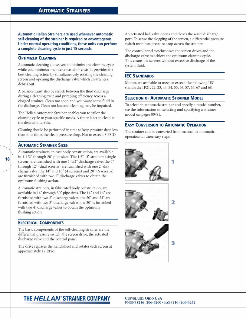
EASY CONVERSION TO AUTOMATIC OPERATION
The strainer can be converted from manual to automatic operation in three easy steps.
1
2
3

19
CLEVELAND, OHIO USAPHONE (216) 206-4200 • FAX (216) 206-4242
AUTOMATIC STRAINERS
HAND/OFF/AUTOMATIC
The rotary H-O-A selector switch allows for three modes ofoperation. In the “Hand” position, the screen drives and flushvalve will be actuated until the switch is returned to off.
In the “OFF” position, the self-cleaning cycle does not function.
In the “AUTOMATIC” mode, there are three ways to initiate a cleaning cycle:
1. Differential pressure switch. As the screen becomes clogged,the pressure drop will increase. At a preset point, a cleaningcycle will start.
2. Internal timer. An automatic interval between cleaningcycles can be set from zero to 100 hours.
3. Manual start. A momentary push-button on the controlpanel will start a cleaning cycle.
SYSTEM SAFETY MONITORS
The control panel is a constant indicator of the status of yoursystem. For example, a panel light illuminates when power isapplied to the strainer motor relay.
If the strainer basket is not thoroughly cleaning during the normal cleaning cycle, the pressure drop continues to increase,causing the high pressure alarm light to illuminate.
This alarm is self-resetting when the differential pressure dropfalls below the set point.
REMOTE OPERATIONS
Manual Cycle StartYou may attach a normally open, momentary push-button tothe control panel terminal strip. The H-O-A switch must be inthe AUTOMATIC position for the cycle to start.
High Pressure Alarm OptionA set of contacts controlled by the high pressure alarm light isavailable as an option.
Hand/Off/AutomaticIf you require these functions at a remote location, the controlpanel H-O-A switch must be disconnected.
IEC STANDARDS
NEMA 12 controls panels meet or exceed IEC IP10 through IP65.
NEMA 4 control panels meet or exceed IEC IP66.NEMA 4X control panels meet or exceed IEC 529 IP66.Control panels are also available with IEC components.
SELECTION OF AUTOMATIC STRAINER CONTROL
Strainer controls are ordered separately from the strainer. Theselection of the control is based on both the number of motors(i.e., “AA”, “SA” & “TSA” types have one motor; “DA” & “WDA”types have two motors; “QA” types have four motors and “HH”types have six motors) and their voltage. The voltage to thecontrol panel must be the same as the motor voltage. To selecta control panel and specify a model number, see the infor -mation on selecting and specifying a control panel model onpage 81.
13”
13”
OTHER OUTSIDECONNECTIONS
PLC
TRANSFORMERFACTORY WIRED
FOR 230 OR460 VOLTS.NONE FOR115 VOLTS.
MAINSWITCH
CONTROL RELAYS
STARTER
OVERLOADRELAYS
MOTORCONNECTIONS
GND
GND
17”
20.25”
MAINSWITCH
SERIAL NUMBERPLATE
WARNINGPLATE
POWERON
CLEANINGCYCLE IN
PROGRESS
CYCLESTART
OFFHAND AUTO
HIGHPRESSURE

CLEVELAND, OHIO USAPHONE (216) 206-4200 • FAX (216) 206-4242
20
EXTERNAL SCRAPER ADJUSTMENT
As an option, TS and D-type Hellan Strainers can be equippedwith an external adjustment for the scrapers or brushes. This isshown in the figure below. The scraper or brush is held inplace by two pulling pins. The pins are o-ring sealed and theoutward ends are threaded, allowing the pins to be tightenedagainst the cover.
Once the scraper or brush is adjusted at the factory, it can bereadjusted to compensate for wear. Brushes should be set tocome into contact with the screen. Scrapers should be set to
A
A
B
B
VIEW A-A
VIEW B-B
JACK SCREW
PULLING COVER
PULLING PIN
SCRAPER SUPPORT COVER
SCRAPER OR BRUSH
SCREEN SURFACE
O-RING SEAL
PULLING SCREW
.005” to .010” away from the surface of the screen. To adjustthe scraper or brush, first loosen the pulling screws. Next, turnthe jack screw clockwise to move the scraper or brush towardsthe screen surface. After the scraper or brush is adjusted, itshould be secured. For a brush, the pulling screws should betightened to secure the brush against the jack screw. For ascraper, the jack screw should be rotated counterclockwiseroughly 45 degrees and the pulling screws should be tightenedto secure the scraper.
21
CLEVELAND, OHIO USAPHONE (216) 206-4200 • FAX (216) 206-4242
PRESSURE SWITCH AND THREE WAY BALL VALVE
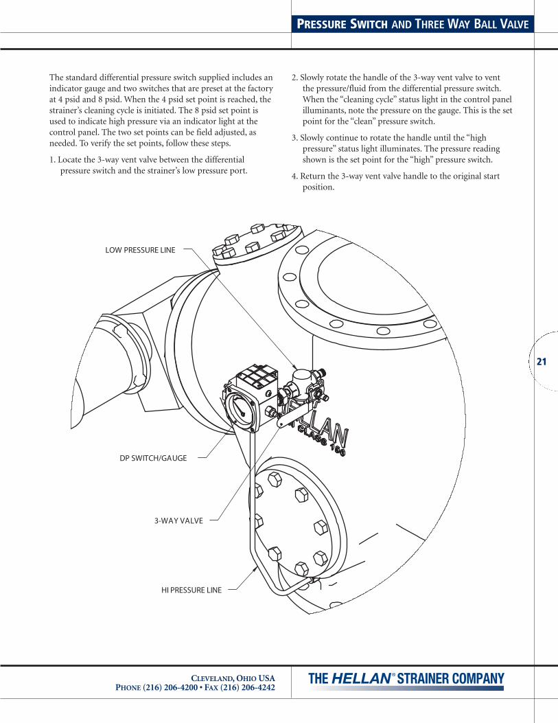
The standard differential pressure switch supplied includes anindicator gauge and two switches that are preset at the factoryat 4 psid and 8 psid. When the 4 psid set point is reached, thestrainer’s cleaning cycle is initiated. The 8 psid set point isused to indicate high pressure via an indicator light at thecontrol panel. The two set points can be field adjusted, asneeded. To verify the set points, follow these steps.
1. Locate the 3-way vent valve between the differentialpressure switch and the strainer’s low pressure port.
2. Slowly rotate the handle of the 3-way vent valve to vent the pressure/fluid from the differential pressure switch.When the “cleaning cycle” status light in the control panelilluminants, note the pressure on the gauge. This is the setpoint for the “clean” pressure switch.
3. Slowly continue to rotate the handle until the “highpressure” status light illuminates. The pressure readingshown is the set point for the “high” pressure switch.
4. Return the 3-way vent valve handle to the original startposition.
DP SWITCH/GAUGE
HI PRESSURE LINE
3-WAY VALVE
LOW PRESSURE LINE

CLEVELAND, OHIO USAPHONE (216) 206-4200 • FAX (216) 206-4242
Outline Page Cv @ Screen Opening (percent of open area)
Hand Auto1/4
(58%)3/16
(51%)1/8
(40%)3/32 (33%)
1/16 (24%)
1/32 (16%)
.015 (27%)
.009 (18%)
.007 (15%)
.005* (11%)
.004* (9%)
1-1/2" & 2" TS 21 36 90.52 89.83 88.00 85.91 80.80 70.69 82.96 74.05 68.72 58.28 51.12
2-1/2" & 3" TS 22 37 133.6 132.6 130.0 127.0 119.6 105.0 122.8 110.0 102.1 86.81 76.25
2" Angle 23 90.52 89.83 88.00 85.91 80.80 70.69 82.96 74.05 68.72 58.28 51.12
2-1/2" Angle 24 121.7 121.0 119.0 116.7 110.9 99.92 113.4 103.0 96.50 83.29 73.84
2-1/2" D-Type 26 162.7 161.7 159.0 155.9 148.1 132.1 151.5 137.5 128.9 111.2 98.56
3" Angle 25 38 159.6 158.6 156.0 153.0 145.4 129.6 148.6 135.0 126.5 109.1 96.72
3" D-Type 27 243.5 242.0 238.0 233.4 221.8 197.8 226.7 205.9 193.0 166.6 147.7
4" D-Type 28 39 295.8 294.2 290.0 285.1 272.7 246.2 278.0 255.3 240.8 210.3 187.8
6" D-Type 29 40 698.1 693.1 680.0 664.9 627.7 556.9 643.5 577.9 538.2 459.2 404.2
8" D-Type 30 41 1235 1225 1200 1171 1101 962.4 1131 1008 935.4 792.7 695.0
10" D-Type 31 42 1695 1683 1650 1612 1519 1334 1553 1396 1292 1104 970.1
12" D-Type 32 43 2200 2186 2150 2108 2003 1786 2048 1860 1743 1504 1333
14" Q-Type 33 44 3609 3579 3500 3410 3193 2770 3284 2909 2689 2265 1929
16" Q-Type 34 46 4507 4477 4400 4310 4087 3629 4182 3784 3538 3041 2689
20" H-Type 35 49 6653 6611 6500 6372 6050 5388 6187 5612 5254 4528 4010
14" WSA* 45 3609 3579 3500 3410 3193 2770 3284 2909 2689 2265 1979
16" WSA* 47 4507 4477 4400 4310 4087 3629 4182 3784 3538 3041 2689
20" WDA* 48 6672 6624 6500 6357 6003 5290 6153 5529 5150 4396 3871
24" WDA* 50 9207 9151 9000 8826 8389 7485 8576 7791 7303 6304 5590
30” WDA* 51 13,890 13,782 13,500 13,178 12,390 10,834 12,134 11,351 10,531 8927 7828
FLOW RATE VS PRESSURE DROP
The table below lists the flow coefficient (Cv) for clean strainer screens.
PRESSURE LOSS CACULATION USING CV FACTOR
Standard Units Metric Units
dP � [ Q ]2dP � [ Q ]2
(133.6)Cv Cv
Q = Flow in GPM Q = Flow in m3/hrCv = Flow Coefficient Cv = Flow CoefficientdP = Pressure Drop in psi dP = Pressure Drop in kPa
The pressure loss across a strainer can be estimated using the system’s flow rate and the Cv factor for that strainer.
22
* Flow coefficients for reference use. Consult factory for additional information.

23
CLEVELAND, OHIO USAPHONE (216) 206-4200 • FAX (216) 206-4242
1-1/2" & 2" MANUAL STRAINERIn-Line Flow Type TSH
1-1/2" NPTCAST IRON1-1/2" NPT
CAST STEEL and STAINLESS STEEL2" NPT
CAST IRON2" NPT
CAST STEEL and STAINLESS STEEL
THREAD SIZE
1-1/2"
2"
STRAINERSIZE
22 kg49 lb21 kg
49 lb22 kg46 lb
46 lb21 kg
APPROX.WEIGHT
INLET
SCRE
EN R
EMO
VA
L
(84mm)3.31Ø
OUTLET
14.50(423mm)
(206mm)8.12
7.50(190mm)
10.06(225mm)
11.69(297mm) 7.00Ø
(178mm)
ORIENTATION - DRAIN MUST BE DOWN.THESE DIMENSIONS ARE FOR REFERENCE ONLY. FOR INSTALLATION PURPOSES, REQUEST CERTIFIED DRAWINGS.
1" NPTSOLIDS FLUSH OUTLET VIEW A-A
WALL
(OPTIONAL BY REQUEST)
STRAIGHT NIPPLE(OPTIONAL BY REQUEST)
A A

CLEVELAND, OHIO USAPHONE (216) 206-4200 • FAX (216) 206-4242
24
THESE DIMENSIONS ARE FOR REFERENCE ONLY. FOR INSTALLATION PURPOSES, REQUEST CERTIFIED DRAWINGS.
1-1/2" NPTSOLIDS FLUSH OUTLET
ORIENTATION - DRAIN MUST BE DOWN.
WALL
VIEW A-A
OUTLET
16.00
(117)4.62
(406)
(294)SCRE
EN R
EMO
VA
L
11.59
(242)9.54
INLET (248)9.75
13.61(346)
STRAIGHT NIPPLE(OPTIONAL BY REQUEST)
(OPTIONAL BY REQUEST)
7.00(178)
2-1/2"
3"
STRAINERSIZE
APPROX.
84 lb38 kg
WEIGHT
40 kg89 lb
84 lb38 kg89 lb40 kg
A A
2-1/2" NPTCAST IRON2-1/2" NPT
CAST STEEL and STAINLESS STEEL3" NPT
CAST IRON3" NPT
CAST STEEL and STAINLESS STEEL
THREAD SIZE
2-1/2" & 3" MANUAL STRAINERIn-Line Flow Type TSH
25
CLEVELAND, OHIO USAPHONE (216) 206-4200 • FAX (216) 206-4242
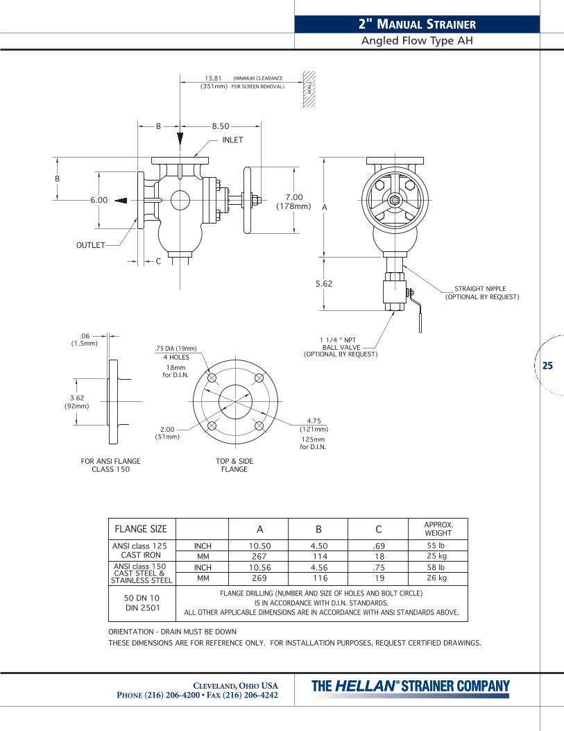
2" MANUAL STRAINERAngled Flow Type AH
6.00
B
B 8.50
(178mm)7.00
A
5.62
INLET
OUTLET
C
13.81(351mm)
(MINIMUM CLEARANCEFOR SCREEN REMOVAL)
1 1/4 " NPT BALL VALVE
(OPTIONAL BY REQUEST)
STRAIGHT NIPPLE(OPTIONAL BY REQUEST)
.75 DIA (19mm)
(92mm)3.62
(51mm)2.00
4 HOLES
.06(1.5mm)
4.75
125mmfor D.I.N.
18mmfor D.I.N.
(121mm)
THESE DIMENSIONS ARE FOR REFERENCE ONLY. FOR INSTALLATION PURPOSES, REQUEST CERTIFIED DRAWINGS.ORIENTATION - DRAIN MUST BE DOWN
WAL
L
CLASS 150 FLANGEFOR ANSI FLANGE TOP & SIDE
4.56114
116
4.50
ALL OTHER APPLICABLE DIMENSIONS ARE IN ACCORDANCE WITH ANSI STANDARDS ABOVE.IS IN ACCORDANCE WITH D.I.N. STANDARDS.
FLANGE DRILLING (NUMBER AND SIZE OF HOLES AND BOLT CIRCLE)
DIN 2501
FLANGE SIZE
CAST IRONANSI class 150CAST STEEL &
ANSI class 125
50 DN 10
STAINLESS STEEL
10.50INCH
MMINCHMM
26910.56267
A55 lb.69
19.7518
26 kg58 lb25 kg
B C APPROX.WEIGHT

CLEVELAND, OHIO USAPHONE (216) 206-4200 • FAX (216) 206-4242
26
A
B
B9.12
6.25
7.00(178mm)
C
(232mm)
INLET
OUTLET
7.00(178mm)
(OPTIONAL BY REQUEST)
1-1/2" NPT BALL VALVE
(OPTIONAL BY REQUEST)STRAIGHT NIPPLE
FOR SCREEN REMOVAL)
(MINIMUM CLEARANCE
(392mm)15.44
THESE DIMENSIONS ARE FOR REFERENCE ONLY. FOR INSTALLATION PURPOSES, REQUEST CERTIFIED DRAWINGS.ORIENTATION - DRAIN MUST BE DOWN
(64mm)
(105mm)4.12
2.50 (140mm)5.50
145mmfor D.I.N.
18mmfor D.I.N.
.75 DIA (19mm)
.06(1.5mm)
4 HOLES
WA
LL
TOP & SIDEFOR ANSI FLANGECLASS 150 FLANGE
65 DN 10
ALL OTHER APPLICABLE DIMENSIONS ARE IN ACCORDANCE WITH ANSI STANDARDS ABOVE.IS IN ACCORDANCE WITH D.I.N. STANDARDS.DIN 2501
FLANGE DRILLING (NUMBER AND SIZE OF HOLES AND BOLT CIRCLE)
ANSI class 125CAST IRON
ANSI class 150CAST STEEL &
STAINLESS STEEL
FLANGE SIZE12.00INCH
MM
MMINCH
310
30512.19
A.69
22.88
5.00
5.19132
127
B70 lb
18
34 kg74 lb32 kg
C APPROX.WEIGHT
2-1/2" MANUAL STRAINERAngled Flow Type AH

27
CLEVELAND, OHIO USAPHONE (216) 206-4200 • FAX (216) 206-4242
3" MANUAL STRAINERAngled Flow Type AH
IS IN ACCORDANCE WITH D.I.N. STANDARDS.ALL OTHER APPLICABLE DIMENSIONS ARE IN ACCORDANCE WITH ANSI STANDARDS ABOVE.
FLANGE DRILLING (NUMBER AND SIZE OF HOLES AND BOLT CIRCLE)
INCH
INCHMM
MMSTAINLESS STEEL
80 DN 10DIN 2501
CAST STEEL &ANSI class 150
FLANGE SIZEANSI class 125
CAST IRON14.19360
A14.00356
FOR ANSI FLANGECLASS 150
TOP & SIDEFLANGE
5.69144
.9424
B5.50140
C.7519 46 kg
105 lb48 kg
WEIGHTAPPROX.
101 lb
THESE DIMENSIONS ARE FOR REFERENCE ONLY. FOR INSTALLATION PURPOSES, REQUEST CERTIFIED DRAWINGS.ORIENTATION - DRAIN MUST BE DOWN
(127mm)
3.00(76mm)
5.00
6.00
100mmfor D.I.N.
18mm8 HOLESfor D.I.N.
(152mm)
FOR SCREEN REMOVAL)(MINIMUM CLEARANCE
OUT
LET
.75 DIA (19mm)(1.5mm)
.06
4 HOLES
1-1/2" NPTSOLIDS FLUSH OUTLET
(159mm)6.25
C
B
7.50(191mm)
(191mm)7.50
B (235mm)
INLETC
9.25
(438mm)17.25
FLANGED INSPECTION OPENINGO-RING SEALED
3.75 (95mm) DIA.
A
(STANDARD)
10.00(254mm)
STRAIGHT NIPPLE(OPTIONAL BY REQUEST)
1 1/2 " NPT BALL VALVE
(OPTIONAL BY REQUEST)
WA
LL

CLEVELAND, OHIO USAPHONE (216) 206-4200 • FAX (216) 206-4242
282.50
(63.5mm)
5.50
145mmfor D.I.N.
18mmfor D.I.N.
(140mm)
.75 DIA (19mm)(4) HOLES
4.12(105mm)
7.00(178mm)
(1.5mm).06
D
G
C
B
D
7.00(178mm)
7.00
3.00 3.50
9.67
5.57
21.74
10.87
STRAIGHT NIPPLE(OPTIONAL BY REQUEST)
1 1/2 BALL VALVE(OPTIONAL BY REQUEST)
THESE DIMENSIONS ARE FOR REFERENCE ONLY. FOR INSTALLATION PURPOSES, REQUEST CERTIFIED DRAWINGS.ORIENTATION - DRAIN MUST BE DOWN
(413mm)16.25
FOR SCREEN REMOVAL)(MINIMUM CLEARANCE
WAL
L
FLANGE DRILLING (NUMBER AND SIZE OF HOLES AND BOLT CIRCLE)IS IN ACCORDANCE WITH D.I.N. STANDARDS.
ALL OTHER APPLICABLE DIMENSIONS ARE IN ACCORDANCE WITH ANSI STANDARDS ABOVE.
FLANGE SIZE
CAST IRONANSI class 125
DIN 250165 DN 10
INCH
INCHMM
MM3.5089
3.6292
B4.691194.81122
C12.00
12.25.8822
.7519
D
311
305
G WEIGHTAPPROX.
100 lb45 kg105 lb48 kgSTAINLESS STEEL
CAST STEEL &ANSI class 150
INLET
OUTLET
2-1/2" MANUAL STRAINERIn-Line Flow Type DH

29
CLEVELAND, OHIO USAPHONE (216) 206-4200 • FAX (216) 206-4242
3" MANUAL STRAINERIn-Line Flow Type DH
23.94
11.97
5.83
7.00
G
13.56
B
C
7.50
4.383.75D
.75 DIA (19mm)4 HOLES
6.00(152mm)
3.00(76mm)
D
.06 (1.5mm)
5.00(127mm)
7.50
STRAIGHT NIPPLE(OPTIONAL BY REQUEST)
2" BALL VALVE(OPTIONAL BY REQUEST)
2" THREADED FLANGE(STANDARD)
(441mm)(MINIMUM CLEARANCEFOR SCREEN REMOVAL)
17.38
ORIENTATION - DRAIN MUST BE DOWNTHESE DIMENSIONS ARE FOR REFERENCE ONLY. FOR INSTALLATION PURPOSES, REQUEST CERTIFIED DRAWINGS.
WA
LL
TOP & BOTTOM FLANGESFOR ANSI FLANGE CLASS 150
FLANGE DRILLING (NUMBER AND SIZE OF HOLES AND BOLT CIRCLE)IS IN ACCORDANCE WITH D.I.N. STANDARDS.
ALL OTHER APPLICABLE DIMENSIONS ARE IN ACCORDANCE WITH ANSI STANDARDS ABOVE.
INCHMM
MM
INCH
FLANGE SIZE
STAINLESS STEELCAST STEEL &ANSI class 150
CAST IRONANSI class 125
DIN 250180 DN 10
2.0648
52
1.88
1254.94
B
1214.75
.9424
D
19.75
61 kg145 lb66 kg
WEIGHTAPPROX.
135 lb
C G13.0033013.38340
160mmfor D.I.N.
18mm8 HOLESfor D.I.N.
1/4 NPT INLET GAUGE PORT
INLET
OUTLET

CLEVELAND, OHIO USAPHONE (216) 206-4200 • FAX (216) 206-4242
30
1/4 NPT INLET GAUGE PORT
1/4 NPTOUTLET GAUGE PORT
THESE DIMENSIONS ARE FOR REFERENCE ONLY. FOR INSTALLATION PURPOSES, REQUEST CERTIFIED DRAWINGS.
FLANGE SIZE A CB D E FINCH
INCH
INCH
INCH
DIN 2501100 DN 16
100 DN 10
ANSI class 300CAST STEEL &
STAINLESS STEEL
DIN 2501
ANSI class 250CAST IRON
CAST IRONANSI class 125
1686.60
MM6.31160114
4.50 6.9417632
1.25254
10.00
6.00
6.00
6.316.60 4.50
1606.29168MM
MM
160
1521064.19114
6.29160MM 152106
4.19
6.941.25 10.00176
1576.19
32
24.94
254
2299.00
NANA24
.942299.00
FOR ANSI FLANGE CLASS250, 150, 300 & DIN
FE
D
(254)10.00
.06 (1.5mm)
R
ACCESS CLEARANCE)(MINIMUM SCREEN
A
(523mm)
WAL
L
20.59
(358mm)14.09
(716mm)28.18
(HOLES)G H RM FLANGE SIZE
2-1/2" NPT
7.88200
16.62422
.8822
88 393
15.4714.10358 2" NPT
.8887.8816.622007.50
422
19140616.00
22
19.75
8
88
7.50191
16.00406
DIA..7519
No.88
15.4712.54
38515.16393318
35013.79
2" NPT
2" NPT
15.16385
16.41416
200 lb90 kg
190 lb
82 kg
86 kg180 lb
77 kg170 lbWEIGHT
N DRAIN
TOP & BOTTOM FLANGES
J
H 4.00(102mm)
J
APPROX.
M
G
C
STRAIGHT OR SWAGE NIPPLE (BY REQUEST)
(OPTIONAL BY REQUEST)
N-THREAD DRAIN FLANGE(STANDARD)
B
2" NPT SOLIDSFLUSH OUTLET
ANSI class 150CAST STEEL &
STAINLESS STEEL
INLET
OUTLET
INCH
INCH
1686.60
MM6.31160114
4.50 6.9417632
1.25254
10.00
6.001606.29
MM 1521064.19
1576.19
24.94
2299.00
7.09180
16.62422
.7118
88 393
15.4714.10358 2" NPT
7.09180406
16.0018.71
88
38515.16
35013.79 2" NPT
200 lb90 kg
82 kg180 lb
4" MANUAL STRAINERIn-Line Flow Type DH

31
CLEVELAND, OHIO USAPHONE (216) 206-4200 • FAX (216) 206-4242
6" MANUAL STRAINERIn-Line Flow Type DH
(OPTIONAL BY REQUEST)
TOP & BOTTOM FLANGES
THESE DIMENSIONS ARE FOR REFERENCE ONLY. FOR INSTALLATION PURPOSES, REQUEST CERTIFIED DRAWINGS.
FLANGE SIZE
CAST IRONANSI class 125
ANSI class 300
CAST IRONANSI class 250
DIN 2501150 DN 16DIN 2501
150 DN 10STAINLESS STEEL
CAST STEEL &
.06 (1.5mm)
NANA
9.69246
9.692168.50
246INCH 9.23MM 234
INCH
INCH
INCH
8.79
9.23MM
MM 223
234
8.79MM 223
A
5.31135 192
7.56 1.4437
135
1244.88
5.31192
181
7.56
7.12
89
B3.50
181
C7.12
1.44
1.0037
25
1.0025
D E
250, 150, 300 & DINFOR ANSI FLANGE CLASS
EF
20.88530
12.50318
10.62270
50820.00
53020.88
50820.00
27911.00
12.50318
27911.00
F
27010.62
2419.50
G
2419.50
H
19.001212
.8822 483 460
18.12
18.95
19.62
19.061212
88
22.88
22.88
(HOLES)
8
JNo.8
22.88DIA.
484
498 44917.68460
18.12481
M R
44917.68
D
H
(254)10.00
A
WAL
L
INLET
(MINIMUM SCREEN
OUTLET
(1124 mm)44.28
22.14(561 mm)
31.00
G
R
3.25 (82mm)
O-RING SEALED
SCREEN INSP.OPENING,
B
455 lb207 kg2 1/2"
182 kg400 lbWEIGHTAPPROX.
195 kg430 lb193 kg425 lb
3"
2 1/2"
3" NPT
FLANGE SIZEDRAINN
6.00(152mm)
J
M
C
(OPTIONAL BY REQUEST)SWAGE NIPPLE
N-THREADDRAIN FLANGE (STANDARD)
2" NPT SOLIDSFLUSH OUTLET
ANSI class 150CAST STEEL &
STAINLESS STEEL
9.692168.50
246INCH 9.23MM 234
INCH 8.79MM 223
5.31135 192
7.56 1.4437
1244.88
1817.12 1.00
2520.88530
12.50318
9.45240
50820.00
27911.00
2409.45
19.0088
.8122 483 460
18.12
19.6288
18.71
498 44917.68
455 lb207 kg2 1/2"
195 kg430 lb3"
1/4 NPT INLET GAUGE PORT

CLEVELAND, OHIO USAPHONE (216) 206-4200 • FAX (216) 206-4242
32
DIN 2501200 DN 10
DIN 2501200 DN 16
CAST IRONANSI class 250
ANSI class 125CAST IRON
STAINLESS STEELCAST STEEL &ANSI class 300
THESE DIMENSIONS ARE FOR REFERENCE ONLY. FOR INSTALLATION PURPOSES, REQUEST CERTIFIED DRAWINGS.
FLANGE SIZE
11.75298
11.75
13.00330
298
13.00330255
10.042429.54
MM
INCH
INCHMM
149 232
5.381375.88
8.622199.12
2429.54
25510.04
INCH
INCHMM
MM
A5.38 8.62137
1495.88
219
2329.12
B C
34313.50
15.0038141 303
11.94
10.621.1229
1.62270
635
24.00610
25.00
34313.50
38115.00
NA1.12
11.9429
411.62
NA
303
D E24.00610
63525.00
GF H
318 kg700 lbWEIGHT
341 kg750 lb
750 lb
800 lb364 kg
341 kg
APPROX.
21.56548
22.1256212 25
.88
1.00
8812
22
59223.32
22.82580
54821.56
55822.00
M.88
1.0088
1212
22
25
(HOLES)No.J
DIA.
23.32
22.82580
592
R
(821mm)32.32
H
TOP & BOTTOM FLANGESFOR ANSI FLANGE CLASS
250, 150, 300 & DIN
EF
CD
.06 (1.5mm)
(203mm)8.00
J
M
C
B
(1160mm)
(580mm)22.82
45.64
ACCESS CLEARANCE)(MINIMUM SCREEN
4.50 (114mm)
OPENING,SCREEN INSP.
O-RING SEALED
(OPTIONAL BY REQUEST)
(OPTIONAL BY REQUEST)SWAGE NIPPLE
2" NPT SOLIDSFLUSH OUTLET
ANSI class 150CAST STEEL &
STAINLESS STEEL
A
(381)15.00
INLET
R G
OUTLET
(OPTIONAL BY REQUEST)DRAIN FLANGE4" THREADED W
ALL
11.61295
11.611295255
10.042429.54
MM
INCH
INCHMM
149 232
5.381375.88
8.622199.12
34313.50
15.0038141 303
11.94
10.621.1229
1.62270
635
24.00610
25.00
750 lb
800 lb364 kg
341 kg21.56548
22.1256212 22
.87
.87
8812
22
59223.32
22.82580
1/4 NPT INLET GAUGE PORT
8" MANUAL STRAINERIn-Line Flow Type DH

33
CLEVELAND, OHIO USAPHONE (216) 206-4200 • FAX (216) 206-4242
10" MANUAL STRAINERIn-Line Flow Type DH
THESE DIMENSIONS ARE FOR REFERENCE ONLY. FOR INSTALLATION PURPOSES, REQUEST CERTIFIED DRAWINGS.
36214.25
387
36214.25
15.25
15.25
387
10.97
11.66
INCH
DIN 2501250 DN 16
STAINLESS STEELCAST STEEL &
250 DN 10DIN 2501
MM
CAST IRON
ANSI class 300MM
INCHMM
ANSI class 125
ANSI class 250CAST IRON MM
INCH
INCH
28.8814.061.886.38 10.19 17.50357259162 48 445 733
12.75357
324
14.06
9.50241
259
1445.69162
301.1948
9.50241
10.191446.38
5.6930
1.88
1.19
406
44516.00
69927.50733
406NA17.50
NA 16.00699
28.88
27.50
23.12 1075 lb16 1.1216 29 587
22.55
22.55
23.00
121216
25 573
291.00
584
1216
1257325
1.12
1.00
630
454 kg1000 lb466 kg
61324.84
24.15432 kg1025 lb
950 lb
250, 150, 300 & DINFOR ANSI FLANGE CLASS
FLANGE SIZE A B C D E F G
EF
C .06 (1.5mm)D
TOP & BOTTOM FLANGES
(HOLES)H No.J
DIA. M R WEIGHTAPPROX.
H 10.00(254mm)
J
M
OUTLET
INLET
B
49.10
ACCESS CLEARANCE)
(1248 mm)
(MINIMUM SCREEN37.00
WAL
L
(624mm)24.55
(940mm) O-RING SEALEDOPENING,SCREEN INSP.4.50 (114mm)
C
SWAGE NIPPLE
FLUSH OUTLET2" NPT SOLIDS
(OPTIONAL BY REQUEST)
(OPTIONAL BY REQUEST)
279
29610.97279
11.66296
24.15613
24.84630
ANSI class 150CAST STEEL &
STAINLESS STEEL
4"THREADED DRAIN FLANGE
(STANDARD)
GR
15.00(381mm)
A
35013.75
13.98355
INCHMM
MMINCH
28.8814.061.886.38 10.19 17.50357259162 48 445 733
12.75324
9.50241144
5.6930
1.19406
16.00699
27.50
23.12 1075 lb12 1.0212 26 587 488 kg
22.551212
22 573.87
454 kg1000 lb10.97
27911.66296
24.15613
24.84630
1/4 NPT INLET GAUGE PORT
488 kg

CLEVELAND, OHIO USAPHONE (216) 206-4200 • FAX (216) 206-4242
34
TOP & BOTTOM FLANGES
SWAGE NIPPLE
THESE DIMENSIONS ARE FOR REFERENCE ONLY. FOR INSTALLATION PURPOSES, REQUEST CERTIFIED DRAWINGS.
250, 150, 300 & DINFOR ANSI FLANGE CLASS
10.75
10.75
11.50
11.50ANSI class 250 INCH 13.55 6.88
STAINLESS STEELCAST STEEL &ANSI class 300
MM 175
300 DN 16DIN 2501
DIN 2501300 DN 10
INCH
INCHMM
CAST IRON MM
6.88156
3446.12175
ANSI class 125
FLANGE SIZEINCH
CAST IRON MM12.80325
6.12156
A B
16.442.00 1.251620.50 33.25 17.75 24.00
84433.25806
31.75844
52141751292
417
38115.00
16.4432
2.00273
511.25
292
48320.50
52119.00
3216451 612
43217.75
1216
45117.00
1612
251.25
59824.12
321.00 23.55
609
31.75806
GENANA
1.2532273
DC
48319.00
F No.17.00432 12
12
H J
251.00 23.55
598
DIA.(HOLES) M
INLET
C .06 (1.5mm)
E
F
D
H
(690mm)27.16
B
OUTLET
(1380mm)
41.32(1049mm)
(MINIMUM SCREENACCESS CLEARANCE)
54.32
O-RING SEALED
SCREEN INSP.4.50 (114mm)
OPENING,
1450 lb26.82
704 kg
659 kg
659 kg1450 lb
1550 lb
681
APPROX.WEIGHT
1350 lb614 kg
26.07662
R
(305mm)12.00
J
M
C
FLUSH OUTLET2" NPT SOLIDS
(OPTIONAL BY REQUEST)
(OPTIONAL BY REQUEST)
12.80325
13.55344
26.07662
26.82681
ANSI class 150CAST STEEL &
STAINLESS STEEL
WAL
L
G
4" THREADEDDRAIN FLANGE(STANDARD)
R
A
15.00(381mm)
10.75
11.50MM 175
INCH
INCHMM
6.881566.12
84433.25806
31.75
52141751292
38115.00
16.4432
2.00273
1.25483
20.50
19.00
2612410 612
40016.14
1212
15.75 1222
1.02598
24.12
.87 23.55
704 kg
659 kg1450 lb
1550 lb
12.80325
13.55344
26.07662
26.82681
1/4 NPT INLET GAUGE PORT
1/4 NPT INLET GAUGE PORT
12" MANUAL STRAINERIn-Line Flow Type DH

35
CLEVELAND, OHIO USAPHONE (216) 206-4200 • FAX (216) 206-4242
14" MANUAL STRAINERIn-Line Flow Type QH
CAST IRON
STAINLESS STEELCAST STEEL &ANSI class 150
ANSI class 125
FLANGE SIZE
29.44MM
INCHMM
748
7562475 lb1125 kg
1034 kg29.75
(356mm)
INCH
A
14.00
2275 lb
APPROX.WEIGHT
TOP & BOTTOM FLANGES
(476mm)18.75
WAL
L
21.00(533mm)
(12) HOLES @ 1.12 DIA
O-RING SEALED
4.00 (102mm)SCREEN INSPECTION OPENING
FOR ANSI CLASS 150
16.25(413mm)
THESE DIMENSIONS ARE FOR REFERENCE ONLY. FOR INSTALLATION PURPOSES, REQUEST CERTIFIED DRAWINGS.
15.2515.25(387mm) (387mm)
(25mm)1.00
12.31(313mm)
(MINIMUM SCREEN
(684mm)26.94
ACCESS CLEARANCE)(940mm)43.00
(344m)
SOLIDS FLUSH OUTLET2" NPT
13.53
(650mm)
A
25.59
1.38(35mm)
(1368mm)53.88
(OPTIONAL BY REQUEST)
SWAGE NIPPLE(OPTIONAL BY REQUEST)
4" THREADEDDRAIN FLANGE(STANDARD)
.06(1.5mm)
OUTLET
INLET
15.00(381mm)
1/4" NPTGAUGE PORT

CLEVELAND, OHIO USAPHONE (216) 206-4200 • FAX (216) 206-4242
36
ANSI class 150CAST STEEL &
STAINLESS STEEL
FLANGE SIZEANSI class 125
CAST IRON
(27mm)
WAL
L
17.00(432mm)
1.06
(432mm)17.00
(384mm)15.12
ACCESS CLEARANCE)(MINIMUM SCREEN
(1054mm)41.50
29 (597mm)
TOP & BOTTOM FLANGES
AINCHMM
INCHMM
32.62829
32.28820
16.00(406mm)
2980 lbWEIGHT
3210 lb1350 kg
1460 kg
APPROX.
54021.25
SCREEN INSPECTION OPENING
SOLIDS FLUSH OUTLET2" NPT
(16) HOLES 1.12
A
23.50
O-RING SEALED
5.00 (127mm)
FOR ANSI CLASS 150
18.50(470mm)
1.44(37mm)
INLET
OUTLET
28.19(716mm)327mm)
14.61
(753mm)29.64
(1506mm)59.28
(OPTIONAL BY REQUEST)
(OPTIONAL BY REQUEST)
THESE DIMENSIONS ARE FOR REFERENCE ONLY. FOR INSTALLATION PURPOSES, REQUEST CERTIFIED DRAWINGS.
SWAGE NIPPLE
.06(1.5mm)
1/4" NPTGAUGE PORT
(STANDARD)DRAIN FLANGE5" THREADED
16" MANUAL STRAINERIn-Line Flow Type QH

37
CLEVELAND, OHIO USAPHONE (216) 206-4200 • FAX (216) 206-4242
20" MANUAL STRAINERIn-Line Flow Type HH
WAL
L
ANSI class 125CAST IRON
STAINLESS STEELCAST STEEL &ANSI class 150
MMINCH
MMINCH
SIZE
1960 kg
3950 lb
4309 lb1790 kg
39.501003
99339.09
A APPROX.WEIGHT
TOP & BOTTOM FLANGES
(483mm)
20.00(508mm)
INLET
27.50(699mm)
25.00(635mm)
18°
A
(483mm)19.00
15.00(381mm)
19.00
1.81(46mm)
5.00
(6 PLACES)SCREEN INSPECTION OPENING
60°
INLET GAUGE PORT PLUG1/4"-NPT
30°
(127mm)
A
16.40(417mm)
29.39(746.5mm)
ACCESS CLEARANCE)(MINIMUM SCREEN
(1092mm)43.00
(938.5mm)36.95
6.44(164mm)
OUTLET GAUGE PORT PLUG1/4"-NPT
THESE DIMENSIONS ARE FOR REFERENCE ONLY. FOR INSTALLATION PURPOSES, REQUEST CERTIFIED DRAWINGS.
(385mm)15.17
OUTLET
(35mm)1.38
SWAGE NIPPLE(OPTIONAL BY REQUEST)
SOLIDS FLUSH OUTLET(OPTIONAL BY REQUEST)
2" NPT
12 HOLES1.12 DIA

CLEVELAND, OHIO USAPHONE (216) 206-4200 • FAX (216) 206-4242
38
FOUN
DRY
MARK
2 INCH
HELL
AN
ASTM A
278-
64 CL
ASS 30
U.S. P
ATENT N
o. RE
3556
0
HEAT
CODE
THREE WAY BALL VALVEPRESSURE SWITCH &
AS SHOWNINSTALLED BY CUST.SUPPLIED BY HELLAN
(200)7.89
(344)13.54
SCRE
EN R
EMO
VA
L
(423)16.64
OUTLET
MOTORIZED DRAIN VALVE
(366)14.41
(190)7.50
(229)
(337)13.27
9.03
INLET
(84)3.31Ø
5.0
25.0
10.0
20.0
15.0
SINGLE SWINCREASE
SET-PT
WALL
SOLIDS FLUSH OUTLET1" NPT
SCREEN DRIVE MOTOR(1/3 H.P.)
THESE DIMENSIONS ARE FOR REFERENCE ONLY. FOR INSTALLATION PURPOSES, REQUEST CERTIFIED DRAWINGS.ORIENTATION - DRAIN MUST BE DOWN.
VIEW A-A
A A
PSIDLO HI
1-1/2" NPTCAST IRON1-1/2" NPT
CAST STEEL and STAINLESS STEEL2" NPT
CAST IRON2" NPT
CAST STEEL and STAINLESS STEEL
THREAD SIZE
1-1/2"
2"
STRAINERSIZE
22 kg49 lb21 kg
49 lb22 kg46 lb
46 lb21 kg
APPROX.WEIGHT
1-1/2" & 2" AUTOMATIC STRAINERIn-Line Flow Type TSA
CLEVELAND, OHIO USAPHONE (216) 206-4200 • FAX (216) 206-4242
38

39
CLEVELAND, OHIO USAPHONE (216) 206-4200 • FAX (216) 206-4242
39
2-1/2" & 3" AUTOMATIC STRAINERIn-Line Flow Type TSA
CLEVELAND, OHIO USAPHONE (216) 206-4200 • FAX (216) 206-4242
(1/3 H.P.)SCREEN DRIVE MOTOR
WALL
SOLIDS FLUSH OUTLET1-1/2" NPT
A-AVIEW
THESE DIMENSIONS ARE FOR REFERENCE ONLY. FOR INSTALLATION PURPOSES, REQUEST CERTIFIED DRAWINGS.ORIENTATION - DRAIN MUST BE DOWN.
PSIDLO HI
9.94(252)
18.50
SCRE
EN R
EMO
VA
L
(470)
(391)15.06
4.62(117)
9.75(248)
14.41(366)
11.05(281)
15.23(387)
INLETOUTLET
MOTORIZED DRAIN VALVE
25.0
15.010.0
20.0
SET-PT
INCREASESINGLE SW
5.0
SUPPLIED BY HELLANINSTALLED BY CUST.
PRESSURE SWITCH & THREE WAY BALL VALVE
AS SHOWN
A A
FOUN
DRY
MARK
2 INCH
HELL
AN
ASTM A
278-
64 CL
ASS 30
U.S. P
ATENT N
o. RE
3556
0
HEAT
CODE
2-1/2"
3"
STRAINERSIZE
APPROX.
84 lb38 kg
WEIGHT
40 kg89 lb
84 lb38 kg89 lb40 kg
2-1/2" NPTCAST IRON2-1/2" NPT
CAST STEEL and STAINLESS STEEL3" NPT
CAST IRON3" NPT
CAST STEEL and STAINLESS STEEL
THREAD SIZE

CLEVELAND, OHIO USAPHONE (216) 206-4200 • FAX (216) 206-4242
40
PRESSURE SWITCHSUPPLIED BY HELLANINSTALLED BY CUST.AS SHOWN
FLANGE DRILLING (NUMBER AND SIZE OF HOLES AND BOLT CIRCLE)
ALL OTHER APPLICABLE DIMENSIONS ARE IN ACCORDANCE WITH ANSI STANDARDS ABOVE.IS IN ACCORDANCE WITH D.I.N. STANDARDS.
CAST IRONANSI class 150
ANSI class 125
CAST STEEL &
DIN 250180 DN 10
MM
MMINCH
INCH
360 14414.19356
14.001405.69
5.50
FLANGE SIZE A B
24
19.94
.75
74 kg
69 kg163 lb
155 lb
C APPROX.WEIGHT
CLASS 150FOR ANSI FLANGE TOP & SIDE
FLANGE
CUSTOMER PIPING
SUPPLIED BY HELLAN STRAINERINSTALLED BY CUST.AS SHOWN
STAINLESS STEEL
PSID
THESE DIMENSIONS ARE FOR REFERENCE ONLY. FOR INSTALLATION PURPOSES, REQUEST CERTIFIED DRAWINGS.
(127mm)5.00
(76mm)3.00
.06(1.5mm)
4 HOLES.75 DIA (19mm)
(152mm)6.00
6.86(174mm)
STRAIGHT NIPPLE
14.75(375mm)
A(191mm)
7.50
(191mm)7.50
B
THREE WAY BALL VALVE
LO HI
B
(MINIMUM CLEARANCE20.25FOR SCREEN REMOVAL)
13.15
SCREEN DRIVE MOTOR(1/3 H.P.)
3.75 (95mm) DIA.
O-RING SEALEDFLANGED INSPECTION OPENING
SOLIDS FLUSH OUTLET1-1/2" NPT
MOTORIZED DRAIN VALVE
C
C
INLET
OUT
LET
ORIENTATION - DRAIN MUST BE DOWN
(334mm)
(514mm)
WA
LL5.0
25.0
10.0
20.0
15.0
INCREASESINGLE SWSET-PT
3" AUTOMATIC STRAINERAngle Flow Type AA

41
CLEVELAND, OHIO USAPHONE (216) 206-4200 • FAX (216) 206-4242
4" AUTOMATIC STRAINERIn-Line Flow Type DA
250, 150, 300 & DINFOR ANSI FLANGE CLASS
FE
TOP & BOTTOM FLANGES
(102mm)H 4.00
J
37.54(953mm)
(MINIMUM SCREENACCESS CLEARANCE)
18.77
B
(477m)
WAL
L (660mm)26.00
R
.06 (1.5mm)D
G
(375mm)
M
14.75
SCREEN DRIVE MOTOR (1/3 H.P.)
A
THREE WAY BALL VALVE
WITH FITTINGSDIFF. PRESSURE SWITCH
(303 mm)
MOTORIZED DRAIN VALVE
SWAGE NIPPLE
11.93
C
2" NPT SOLIDSFLUSH OUTLET
10.0 15.0
5.0 20.0
25.0
OUTLET
INLET
PSID
THESE DIMENSIONS ARE FOR REFERENCE ONLY. FOR INSTALLATION PURPOSES, REQUEST CERTIFIED DRAWINGS.
FLANGE SIZE A CB D E FINCH
INCH
INCH
INCH
DIN 2501100 DN 16
100 DN 10
ANSI class 300CAST STEEL &
STAINLESS STEEL
DIN 2501
ANSI class 250CAST IRON
CAST IRONANSI class 125
1686.60
MM6.31160114
4.50 6.9417632
1.25254
10.00
6.00
6.00
6.316.60 4.50
1606.29168MM
MM
160
1521064.19114
6.29160MM 152106
4.19
6.941.25 10.00176
1576.19
32
24.94
254
2299.00
NANA24
.942299.00
(HOLES)G H RM FLANGE SIZE
2-1/2" NPT
7.88200
16.62422
.8822
88 393
15.4714.10358 2" NPT
.8887.8816.622007.50
422
19140616.00
22
19.75
8
88
7.50191
16.00406
DIA..7519
No.88
15.4712.54
38515.16393318
35013.79
2" NPT
2" NPT
15.16385
16.41416
200 lb90 kg
190 lb
82 kg
86 kg180 lb
77 kg170 lbWEIGHT
N DRAINJ APPROX.
ANSI class 150CAST STEEL &
STAINLESS STEEL
INCH
INCH
1686.60
MM6.31160114
4.50 6.9417632
1.25254
10.00
6.001606.29
MM 1521064.19
1576.19
24.94
2299.00
7.09180
16.62422
.7118
88 393
15.4714.10358 2" NPT
7.09180406
16.0018.71
88
38515.16
35013.79 2" NPT
200 lb90 kg
82 kg180 lb

CLEVELAND, OHIO USAPHONE (216) 206-4200 • FAX (216) 206-4242
42
FLUSH OUTLET2" NPT SOLIDS
MOTORIZED DRAIN VALVE
(375mm)
TOP & BOTTOM FLANGES
B
WAL
L
THREE WAY BALL VALVE
.06 (1.5mm)
250, 150, 300 & DINFOR ANSI FLANGE CLASS
FE
INLET
D
H
A
R
G
O-RING SEALEDOPENING,SCREEN INSP.3.25 (82mm)
WITH FITTINGSDIFF. PRESSURE SWITCH
OUTLET
(1124 mm)
ACCESS CLEARANCE)31.00 (MINIMUM SCREEN
22.14(561 mm)
(787 mm)
44.28SCREEN DRIVE MOTOR (1/3 H.P.)
SWAGE NIPPLE
13.54(344mm)
6.00(152mm)
J
M
14.75
C
25.0
20.0
15.0
5.0
10.0
PSID
THESE DIMENSIONS ARE FOR REFERENCE ONLY. FOR INSTALLATION PURPOSES, REQUEST CERTIFIED DRAWINGS.
FLANGE SIZE
CAST IRONANSI class 125
ANSI class 300
CAST IRONANSI class 250
DIN 2501150 DN 16DIN 2501
150 DN 10STAINLESS STEEL
CAST STEEL &
NANA
9.69246
9.692168.50
246INCH 9.23MM 234
INCH
INCH
INCH
8.79
9.23MM
MM 223
234
8.79MM 223
A
5.31135 192
7.56 1.4437
135
1244.88
5.31192
181
7.56
7.12
89
B3.50
181
C7.12
1.44
1.0037
25
1.0025
D E
20.88530
12.50318
10.62270
50820.00
53020.88
50820.00
27911.00
12.50318
27911.00
F
27010.62
2419.50
G
2419.50
H
19.001212
.8822 483 460
18.12
18.95
19.62
19.061212
88
22.88
22.88
(HOLES)
8
JNo.8
22.88DIA.
484
498 44917.68460
18.12481
M R
44917.68
455 lb207 kg2 1/2"
182 kg400 lbWEIGHTAPPROX.
195 kg430 lb193 kg425 lb
3"
2 1/2"
3" NPT
FLANGE SIZEDRAINN
ANSI class 150CAST STEEL &
STAINLESS STEEL
9.692168.50
246INCH 9.23MM 234
INCH 8.79MM 223
5.31135 192
7.56 1.4437
1244.88
1817.12 1.00
2520.88530
12.50318
9.45240
50820.00
27911.00
2409.45
19.0088
.8122 483 460
18.12
19.6288
18.71
498 44917.68
455 lb207 kg2 1/2"
195 kg430 lb3"
6" AUTOMATIC STRAINERIn-Line Flow Type DA

43
CLEVELAND, OHIO USAPHONE (216) 206-4200 • FAX (216) 206-4242
8" AUTOMATIC STRAINERIn-Line Flow Type DA
36.00 (MINIMUM SCREEN(893mm)
B
H
TOP & BOTTOM FLANGES250, 150, 300 & DINFOR ANSI FLANGE CLASS
FE
(203mm)8.00
(356mm)
SCREEN DRIVE MOTOR (1/3 H.P.)
C .06 (1.5mm)D
ACCESS CLEARANCE)
(1274mm)
(637mm)25.08
50.16
R
G
A
4.50 (114mm)
O-RING SEALED
SCREEN INSP.OPENING,
WITH FITTINGS
M
J
(375mm)14.75
C
SWAGE NIPPLE
14.00
DIFF. PRESSURE SWITCH MOTORIZED DRAIN VALVE
FLUSH OUTLET2" NPT SOLIDS
INLET
PSID
OUTLET
THREE WAY BALL VALVE
WAL
L
25.0
20.05.015.010.0
DIN 2501200 DN 10
DIN 2501200 DN 16
CAST IRONANSI class 250
ANSI class 125CAST IRON
STAINLESS STEELCAST STEEL &ANSI class 300
THESE DIMENSIONS ARE FOR REFERENCE ONLY. FOR INSTALLATION PURPOSES, REQUEST CERTIFIED DRAWINGS.
FLANGE SIZE
11.75298
11.75
13.00330
298
13.00330255
10.042429.54
MM
INCH
INCHMM
149 232
5.381375.88
8.622199.12
2429.54
25510.04
INCH
INCHMM
MM
A5.38 8.62137
1495.88
219
2329.12
B C
34313.50
15.0038141 303
11.94
10.621.1229
1.62270
635
24.00610
25.00
34313.50
38115.00
NA1.12
11.9429
411.62
NA
303
D E24.00610
63525.00
GF H
318 kg700 lbWEIGHT
341 kg750 lb
750 lb
800 lb364 kg
341 kg
APPROX.
21.56548
22.1256212 25
.88
1.00
8812
22
59223.32
22.82580
54821.56
55822.00
M.88
1.0088
1212
22
25
(HOLES)No.J
DIA.
23.32
22.82580
592
R
ANSI class 150CAST STEEL &
STAINLESS STEEL
11.61295
11.611295255
10.042429.54
MM
INCH
INCHMM
149 232
5.381375.88
8.622199.12
34313.50
15.0038141 303
11.94
10.621.1229
1.62270
635
24.00610
25.00
750 lb
800 lb364 kg
341 kg21.56548
22.1256212 22
.87
.87
8812
22
59223.32
22.82580

CLEVELAND, OHIO USAPHONE (216) 206-4200 • FAX (216) 206-4242
44
B
(MINIMUM SCREEN
(1409 mm)
(705 mm)
ACCESS CLEARANCE)(1040 mm)
27.75
41.00
55.50WAL
L
R
G
A
4.50 (114mm)SCREEN INSP.OPENING,O-RING SEALED
DIFF. PRESSURE SWITCHWITH FITTINGS MOTORIZED DRAIN VALVE
SWAGE NIPPLE
SCREEN DRIVE MOTOR (1/3 H.P.)
(375mm)14.75
M
C
2" NPT SOLIDSFLUSH OUTLET
TOP & BOTTOM FLANGESFOR ANSI FLANGE CLASS
250, 150, 300 & DIN
FE H
(254mm)10.00
C .06 (1.5mm)D
J
OUTLET
INLET
14.72(374mm)
THREE WAY BALL VALVE
PSID
10.0 15.0
5.0 20.0
25.0
THESE DIMENSIONS ARE FOR REFERENCE ONLY. FOR INSTALLATION PURPOSES, REQUEST CERTIFIED DRAWINGS.
36214.25
387
36214.25
15.25
15.25
387
10.97
11.66
INCH
DIN 2501250 DN 16
STAINLESS STEELCAST STEEL &
250 DN 10DIN 2501
MM
CAST IRON
ANSI class 300MM
INCHMM
ANSI class 125
ANSI class 250CAST IRON MM
INCH
INCH
28.8814.061.886.38 10.19 17.50357259162 48 445 733
12.75357
324
14.06
9.50241
259
1445.69162
301.1948
9.50241
10.191446.38
5.6930
1.88
1.19
406
44516.00
69927.50733
406NA17.50
NA 16.00699
28.88
27.50
23.12 1075 lb16 1.1216 29 587 488 kg
22.55
22.55
23.00
121216
25 573
291.00
584
1216
1257325
1.12
1.00
630
454 kg1000 lb466 kg
61324.84
24.15432 kg1025 lb
950 lb
FLANGE SIZE A B C D E F G (HOLES)H No.J
DIA. M R WEIGHTAPPROX.
279
29610.97279
11.66296
24.15613
24.84630
ANSI class 150CAST STEEL &
STAINLESS STEEL
35013.75
13.98355
INCHMM
MMINCH
28.8814.061.886.38 10.19 17.50357259162 48 445 733
12.75324
9.50241144
5.6930
1.19406
16.00699
27.50
23.12 1075 lb12 1.0212 26 587 488 kg
22.551212
22 573.87
454 kg1000 lb10.97
27911.66296
24.15613
24.84630
10" AUTOMATIC STRAINERIn-Line Flow Type DA

45
CLEVELAND, OHIO USAPHONE (216) 206-4200 • FAX (216) 206-4242
12" AUTOMATIC STRAINERIn-Line Flow Type DA
WITH FITTINGSDIFF. PRESSURE SWITCH
(1140mm) ACCESS CLEARANCE)(MINIMUM SCREEN45.00
30.34(771mm)
B
R
A
4.50 (114mm)SCREEN INSP.OPENING,O-RING SEALED
MOTORIZED DRAIN VALVESWAGE NIPPLE
SCREEN DRIVE MOTOR (1/3 HP)
C
M
(375mm)
2" NPT SOLIDSFLUSH OUTLET
F
E
D
H
C .06 (1.5mm)
J
(305mm)12.00
FOR ANSI FLANGE CLASS250, 150, 300 & DIN TOP & BOTTOM FLANGES
G
(1541mm)60.68
OUTLET
INLET
(414mm)
WAL
L
10.0 15.0
5.0 20.0
25.0
14.75
16.29
THREE WAY BALL VALVE
PSID
THESE DIMENSIONS ARE FOR REFERENCE ONLY. FOR INSTALLATION PURPOSES, REQUEST CERTIFIED DRAWINGS.
10.75
10.75
11.50
11.50ANSI class 250 INCH 13.55 6.88
STAINLESS STEELCAST STEEL &ANSI class 300
MM 175
300 DN 16DIN 2501
DIN 2501300 DN 10
INCH
INCHMM
CAST IRON MM
6.88156
3446.12175
ANSI class 125
FLANGE SIZEINCH
CAST IRON MM12.80325
6.12156
A B
16.442.00 1.251620.50 33.25 17.75 24.00
84433.25806
31.75844
52141751292
417
38115.00
16.4432
2.00273
511.25
292
48320.50
52119.00
3216451 612
43217.75
1216
45117.00
1612
251.25
59824.12
321.00 23.55
609
31.75806
GENANA
1.2532273
DC
48319.00
F No.17.00432 12
12
H J
251.00 23.55
598
DIA.(HOLES) M
1450 lb26.82
704 kg
659 kg
659 kg1450 lb
1550 lb
681
APPROX.WEIGHT
1350 lb614 kg
26.07662
R
12.80325
13.55344
26.07662
26.82681
ANSI class 150CAST STEEL &
STAINLESS STEEL
10.75
11.50MM 175
INCH
INCHMM
6.881566.12
84433.25806
31.75
52141751292
38115.00
16.4432
2.00273
1.25483
20.50
19.00
2612410 612
40016.14
1212
15.75 1222
1.02598
24.12
.87 23.55
704 kg
659 kg1450 lb
1550 lb
12.80325
13.55344
26.07662
26.82681

CLEVELAND, OHIO USAPHONE (216) 206-4200 • FAX (216) 206-4242
46
14" AUTOMATIC STRAINERIn-Line Flow Type QA
TOP & BOTTOM FLANGES
14.00(356mm)
18.75
(12) HOLES @ 1.12 DIA(533mm)
21.00
DIFF. PRESSURE SWITCHWITH FITTINGS SCREEN INSPECTION OPENING
4.00 (102mm)
O-RING SEALED
SCREEN DRIVE MOTORS (1/3 HP)
THREE WAY BALL VALVE
WAL
L
ANSI class 150CAST STEEL &
STAINLESS STEEL
FLANGE SIZE
CAST IRONANSI class 125
INCHMM
29.44748
INCHMM
A
75629.75
1818 kg
1909 kg4200 lb
WEIGHTAPPROX.
4000 lb
(476mm)
FOR ANSI CLASS 150
16.25(413mm)
10.0
5.0
25.0
15.0
20.0
PSID
(940mm) ACCESS CLEARANCE)
30.24(768mm)
(MINIMUM SCREEN43.00
(441mm)17.36
(596mm)23.47
A
(35mm)1.381.00
(25mm)
THESE DIMENSIONS ARE FOR REFERENCE ONLY. FOR INSTALLATION PURPOSES, REQUEST CERTIFIED DRAWINGS.
DRAIN VALVEMOTORIZED
INLET
OUTLET
SOLIDS FLUSH OUTLET2" NPT
(349mm)13.72
15.25(387mm)
15.25(387mm)
.06(1.5mm)

47
CLEVELAND, OHIO USAPHONE (216) 206-4200 • FAX (216) 206-4242
14" AUTOMATIC STRAINERIn-Line Flow Type WSA
10.05.0
25.0
15.020.0IN
AIR VENT
SCREEN DRIVEMOTOR 1/2 HP
DIFFERENTIAL PRESSURE SWITCH AND GAUGE
1.00 DIA THRU (12) HOLEEQ. SP. ON A 18.75 B.C.(ANSI CLASS 150)
THREE WAY BALL VALVE
16.3
8
22.8
8
25.00
15.50
22.0
019
.50
39.3
128
.00
38.00
.88 DIA THRU (4) HOLESEQ. SP. ON A 28.00 B.C.
ACCESS FOR FUTURE BACKWASH INSTALLATION. INTERNAL BACKWASH COMPONENTS ARE OPTIONAL BY REQUEST
.75 DIA THRU (4) HOLESEQ. SP. ON A 6.00 B.C.(ANSI CALSS 150)
DRAIN
CLEAN OUT ACCESS
LIFT POINT(2) PLACES
SCRAPER AND SCREENINSPECTION OPENING
89.5
0
PSID
INLET OUTLET
(MIN
IMU
M S
CRE
EN A
CC
ESS
CLE
AR
AN
CE)
PLU
S LI
FT R
IGG
ING
THESE DIMENSIONS ARE FOR REFERENCE ONLY. FOR INSTALLATION PURPOSES, REQUEST CERTIFIED DRAWINGS.
Weight – 1392 lb /633 kg

CLEVELAND, OHIO USAPHONE (216) 206-4200 • FAX (216) 206-4242
48
16" AUTOMATIC STRAINERIn-Line Flow Type QA
WA
LL
48.00 (MINIMUM SCREENACCESS CLEARANCE)(1220mm) 33.13
(1683mm)66.26
1.44(37mm)
5.00 (127mm)
O-RING SEALEDSCREEN INSPECTION OPENING
19.84
(659mm)
(504mm)
25.95
32.62
(432mm)17.00 17.00
(432mm)
15.34(390mm)
2" NPTSOLIDS FLUSH OUTLET
DIFF. PRESSURE SWITCHWITH FITTINGS
SCREEN DRIVE MOTORS (1/3 HP)
1.06(27mm)
(406mm)16.00
(597mm)23.50
TOP & BOTTOM FLANGES
1.1229
21.25540
(842mm)
THREE WAY BALL VALVE
ANSI class 125
FLANGE SIZE
STAINLESS STEELCAST STEEL &ANSI class 150
MMINCH
CAST IRON MMINCH
2190 kg
2090 kg
82032.2882932.62
A
4830 lb
WEIGHT4600 lb
APPROX.
A
FOR ANSI CLASS 150
(470mm)18.50
5.0 20.0
25.0
10.0 15.0
SINGLE SWSET-PT
INCREASE
PSID
SWAGE NIPPLE
MOTORIZEDDRAIN VALVE
THESE DIMENSIONS ARE FOR REFERENCE ONLY. FOR INSTALLATION PURPOSES, REQUEST CERTIFIED DRAWINGS.
(1.5mm).06
INLET
OUTLET

49
CLEVELAND, OHIO USAPHONE (216) 206-4200 • FAX (216) 206-4242
16" AUTOMATIC STRAINERIn-Line Flow Type WSA
IN 10.05.0
25.0
15.020.0
AIR VENT
SCREEN DRIVEMOTOR 1/2 HP
1.00 DIA THRU (16) HOLEEQ. SP. ON A 21.25 B.C.(ANSI CLASS 150)
THREE WAY BALL VALVELIFT POINT(2) PLACES
SCRAPER AND SCRENINSPECTION OPENING
DIFFERENTIAL PRESSURE SWITCH AND GAUGE
CLEAN OUT ACCESS
DRAIN
.75 DIA THRU (4) HOLESEQ. SP. ON A 6.00 B.C.(ANSI CLASS 150)
22.8
8
16.3
8
28.00
18.50.88 DIA THRU (4) HOLESEQ. SP. ON A 32.00 B.C.
ACCESS FOR FUTURE BACKWASH INSTALLATION. INTERNAL BACKWASH COMPONENTS ARE OPTIONAL BY REQUEST
25.3
819
.50
28.0
044
.94
44.00
98.5
0
INLET OUTLET
PSID
(MIN
IMU
M S
CRE
EN A
CC
ESS
CLE
AR
AN
CE)
PLU
S LI
FT R
IGG
ING
THESE DIMENSIONS ARE FOR REFERENCE ONLY. FOR INSTALLATION PURPOSES, REQUEST CERTIFIED DRAWINGS.
Weight – 1771 lb /805 kg

CLEVELAND, OHIO USAPHONE (216) 206-4200 • FAX (216) 206-4242
50
1.12 DIA THRU (4) HOLESQE. SP. ON A 40.00 B.C.DRAIN
SCRAPER AND SCREEN INSPECTION OPENING
CLEAN OUT ACCESS ACCESS FOR FUTURE BACKWASHINSTALLATION. INTERNAL BACKWASH COMPONENTS ARE OPTIONAL BY REQUEST
AIR VENT
LIFT POINT
MOTORIZED DRAIN VALVE
.75 DIA THRU (4) HOLESEQ. SP. ON A 6.00 B.C.
(ANSI CLASS 150)
1.25 DIA THRU (20) HOLEEQ. SP. ON A 25.00 B.C.(ANSI CLASS 150)
THREE WAY BALL VALVE
DIFFERENTIAL PRESSURE SWITCH AND GAUGE
SCREEN DRIVEMOTOR 1/2 HP
32.5021.50
28.2
5
23.2
5
8.00
2.25
23.0
025
.00
50.00
36.2
547
.00
IN20.0
15.0
25.0
5.010.0
CW
RO
T.M
TR.
NAMEPLATE
INLET OUTLET
PSID
CC
W R
OT.
MTR
.
110.
00PL
US
LIFT
RIG
GIN
G
(MIN
IMU
M S
CRE
EN A
CC
ESS
CLE
ARA
NC
E)
THESE DIMENSIONS ARE FOR REFERENCE ONLY. FOR INSTALLATION PURPOSES, REQUEST CERTIFIED DRAWINGS.
20" AUTOMATIC STRAINERIn-Line Flow Type WDA
Weight – 2750 lb /1250 kg

51
CLEVELAND, OHIO USAPHONE (216) 206-4200 • FAX (216) 206-4242
20" AUTOMATIC STRAINERIn-Line Flow Type HA
(584mm)23.00
ANSI class 150CAST STEEL &
STAINLESS STEEL
FLANGE SIZE
CAST IRONANSI class 125
INCHMM
39.09993
INCHMM
A
100339.50
2588 kg
13288 kg6040 lb
WEIGHTAPPROX.
5750 lb
FOR ANSI CLASS 150
WAL
L
WITH FITTINGS
THREE WAY BALL VALVE
DIFF. PRESSURE SWITCH
SINGLE SWSET-PT
INCREASE
5.0 20.0
25.0
15.010.0
THESE DIMENSIONS ARE FOR REFERENCE ONLY. FOR INSTALLATION PURPOSES, REQUEST CERTIFIED DRAWINGS.
TOP & BOTTOM FLANGES
20.00(508mm)
1.38(35mm)
(544mm)21.44
.06(1.5mm)
19.00(483mm)
19.00(483mm)
DRAIN VALVEMOTORIZED
(20) HOLES @ 1.19 DIA
SOLIDS FLUSH OUTLET2" NPT
(390mm)15.34
(46mm)1.81
A
(691mm)27.20
25.00
27.50(699mm)
PSID
(MINIMUM SCREENACCESS CLEARANCE)(1270mm)
(896mm)35.29
50.00
SCREEN DRIVE MOTORS (1/3 HP)O-RING SEALED
SCREEN INSPECTION OPENING5.00 (127mm)
INLET
OUTLET

CLEVELAND, OHIO USAPHONE (216) 206-4200 • FAX (216) 206-4242
52
58.00
11.00
4.12
41.2
552
.75
29.8
830
.50
30.7
5
36.50
CLEAN OUT ACCESS
1.12 DIA THRU (4) HOLESQE. SP. ON A 48.00 B.C.
DRAIN
25.50
25.7
5
ACCESS FOR FUTURE BACKWASHINSTALLATION. INTERNAL BACKWASH COMPONENTS ARE OPTIONAL BY REQUEST
.75 DIA THRU (4) HOLESEQ. SP. ON A 6.00 B.C.
(ANSI CLASS 150)
SCRAPER AND SCREENINSPECTION OPENING
DIFFERENTIAL PRESSURESWITCH AND GAUGE
THREE WAY BALL VALVE
MOTORIZED DRAIN VALVE
LIFT POINT
1.25 DIA THRU (20) HOLEEQ. SP. ON A 29.50 B.C.(ANSI CLASS 150)
AIR VENT
SCREEN DRIVEMOTOR 1/2 HP
IN
20.015.0
25.0
5.010.0
NAMEPLATE
CW
RO
T.M
TR.
CC
W R
OT.
MTR.
OUTLETINLET
PSID
(MIN
IMU
M S
CRE
EN A
CC
ESS
CLE
ARA
NC
E)12
5.00
PLU
S LI
FT R
IGG
ING
THESE DIMENSIONS ARE FOR REFERENCE ONLY. FOR INSTALLATION PURPOSES, REQUEST CERTIFIED DRAWINGS.
24" AUTOMATIC STRAINERIn-Line Flow Type WDA
Weight – 3590 lb /1632 kg

53
CLEVELAND, OHIO USAPHONE (216) 206-4200 • FAX (216) 206-4242
30" AUTOMATIC STRAINERIn-Line Flow Type WDA
SCREEN DRIVEMOTOR 1/2 HP
DIFFERENTIAL PRESSURESWITCH AND GAUGE
.75 DIA THRU (4) HOLESEQ. SP. ON A 6.00 B.C.
(ANSI CLASS 150)
SCRAPER AND SCREENINSPECTION OPENING
CC
W R
OT.
MTR
.
10.05.0
25.0
15.020.0
MTR
.C
CW
RO
T.
MTR.
CC
W RO
T.
MTR
.C
CW
RO
T.
AIR VENT
THREE WAY BALL VALVE
1.38 DIA THRU (28) HOLEEQ. SP. ON A 36.00 B.C.(AWWA CLASS 125)
LIFT POINT
MOTORIZED DRAIN VALVE
CLEAN OUT ACCESS
DRAIN
1.12 DIA THRU (4) HOLESQE. SP. ON A 60.00 B.C.
ACCESS FOR FUTURE BACKWASHINSTALLATION. INTERNAL BACKWASH COMPONENTS ARE OPTIONAL BY REQUEST
PSID
INLET OUTLET
33.00 44.00
45.7
5
36.7
5
35.2
537
.18
53.7
563
.16
12.50
76.00
153.
00PL
US
LIFT
RIG
GIN
G
(MIN
IMU
M S
CRE
EN A
CC
ESS
CLE
ARA
NC
E)
THESE DIMENSIONS ARE FOR REFERENCE ONLY. FOR INSTALLATION PURPOSES, REQUEST CERTIFIED DRAWINGS.
Weight – 5020 lb /7000 kg

11⁄2" & 2" TSH/TSA AND 2" AH STRAINERClean Pressure Drop vs. Flow Rate
CLEVELAND, OHIO USAPHONE (216) 206-4200 • FAX (216) 206-4242
54
1 1.5 2 2.5 3(×10)
4 5 6 7 8 9100 1.5 2 2.5 3
(×100)4 5 6 7 8 9 1000
Water Flow Rate GPM
Pre
ssur
e D
rop
, PS
I
1098
7
6
5
4
3
2.5
2
1.5
1.9.8
.7
.6
.5
.4
.3
.25
.2
.15
.1
1/4, 3/16" Scr. Perf.
1/8" Scr. Perf.
1/16, 1/32" Scr. Perf.
3/32" Scr. Perf.
.70
Pre
ssur
e D
rop
, Bar
s*
.60
.50
.40
.35
.30
.25
.20
.15
.10
.070
.060
.050
.040
.030
.025
.020
.015
.010
.007
200100 300 500 600 700 800400 100050 60 70 8040 1500 2000 3000 3800Water Flow Rate, Liters Per Minute**

1 1.5 2 2.5 3 4 5 6 7 8 9100 1.5 2 2.5 3 4 5 6 7 8 9
Water Flow Rate GPM
Pre
ssur
e D
rop
, PS
I
1098
7
6
5
4
3
2.5
2
1.5
.015" Wedge-Wire
.009" Wedge-Wire
.007" Wedge-Wire
.005" Wedge-Wire
.004" Wedge-Wire
.70
Pre
ssur
e D
rop
, Bar
s*
.60
.50
.40
.35
.30
.25
.20
.15
.10
.070
.060
.050
.040
.030
.025
.020
.015
.010
.007
200100 300 500 600 700 800400 100050 60 70 8040 1500 2000 3000 3800Water Flow Rate, Liters Per Minute**
(×10)(×100)
1000
1.9.8
.7
.6
.5
.4
.3
.25
.2
.15
.1
55
11⁄2" & 2" TSH/TSA STRAINERClean Pressure Drop vs. Flow Rate
CLEVELAND, OHIO USAPHONE (216) 206-4200 • FAX (216) 206-4242

3" DH STRAINERSClean Pressure Drop vs. Flow Rate
CLEVELAND, OHIO USAPHONE (216) 206-4200 • FAX (216) 206-4242
56
1 1.5 2 2.5 3 4 5 6 7 8 9100 1.5 2 2.5 3 4 5 6 7 8 9
Water Flow Rate GPM
Pre
ssur
e D
rop
, PS
I
1098
7
6
5
4
3
2.5
2
1.5
1/4, 3/16" Scr. Perf.
1/8" Scr. Perf.
1/16, 1/32" Scr. Perf.
3/32" Scr. Perf.
.70
Pre
ssur
e D
rop
, Bar
s*
.60
.50
.40
.35
.30
.25
.20
.15
.10
.070
.060
.050
.040
.030
.025
.020
.015
.010
.007
200100 300 500 600 700 800400 100050 60 70 8040 1500 2000 3000 3800Water Flow Rate, Liters Per Minute**
(×10)(×100)
1000
1.9.8
.7
.6
.5
.4
.3
.25
.2
.15
.1

1 1.5 2 2.5 3 4 5 6 7 8 9100 1.5 2 2.5 3 4 5 6 7 8 9
Water Flow Rate GPM
Pre
ssur
e D
rop
, PS
I
1098
7
6
5
4
3
2.5
2
1.5
.70
Pre
ssur
e D
rop
, Bar
s*
.60
.50
.40
.35
.30
.25
.20
.15
.10
.070
.060
.050
.040
.030
.025
.020
.015
.010
.007
200100 300 500 600 700 800400 100050 60 70 8040 1500 2000 3000 3800Water Flow Rate, Liters Per Minute**
(×10)(×100)
1000
1.9.8
.7
.6
.5
.4
.3
.25
.2
.15
.1
1/4, 3/16" Scr. Perf.
1/8" Scr. Perf.
1/16, 1/32" Scr. Perf.
3/32" Scr. Perf.
57
2-1/2" AH STRAINERSClean Pressure Drop vs. Flow Rate
CLEVELAND, OHIO USAPHONE (216) 206-4200 • FAX (216) 206-4242
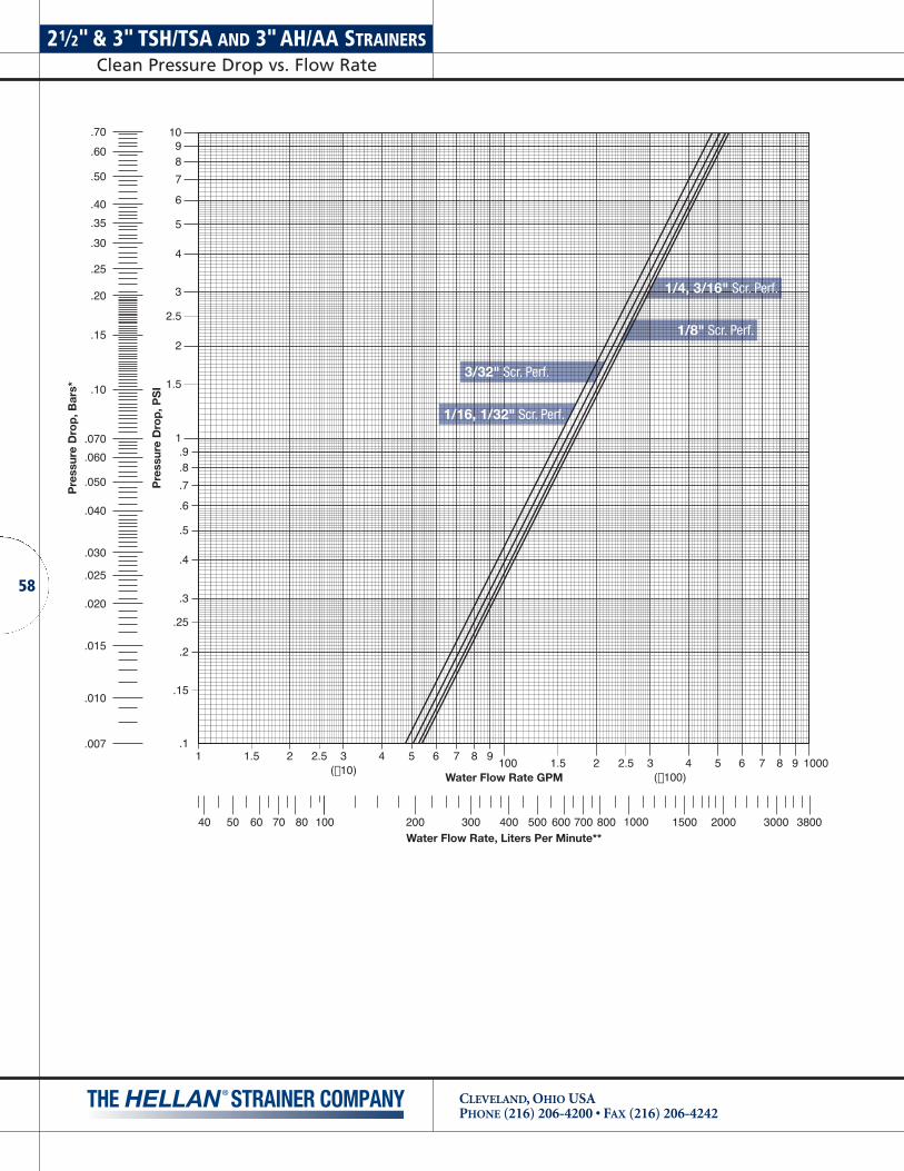
21⁄2" & 3" TSH/TSA AND 3" AH/AA STRAINERSClean Pressure Drop vs. Flow Rate
CLEVELAND, OHIO USAPHONE (216) 206-4200 • FAX (216) 206-4242
58
1 1.5 2 2.5 3 4 5 6 7 8 9100 1.5 2 2.5 3 4 5 6 7 8 9
Water Flow Rate GPM
Pre
ssur
e D
rop
, PS
I
1098
7
6
5
4
3
2.5
2
1.5
1/4, 3/16" Scr. Perf.
1/8" Scr. Perf.
1/16, 1/32" Scr. Perf.
3/32" Scr. Perf.
.70
Pre
ssur
e D
rop
, Bar
s*
.60
.50
.40
.35
.30
.25
.20
.15
.10
.070
.060
.050
.040
.030
.025
.020
.015
.010
.007
200100 300 500 600 700 800400 100050 60 70 8040 1500 2000 3000 3800Water Flow Rate, Liters Per Minute**
(×10)(×100)
1000
1.9.8
.7
.6
.5
.4
.3
.25
.2
.15
.1

1 1.5 2 2.5 3 4 5 6 7 8 9100 1.5 2 2.5 3 4 5 6 7 8 9
Water Flow Rate GPM
Pre
ssur
e D
rop
, PS
I
1098
7
6
5
4
3
2.5
2
1.5
.015" Wedge-Wire
.009" Wedge-Wire
.007" Wedge-Wire
.005" Wedge-Wire
.004" Wedge-Wire
.70
Pre
ssur
e D
rop
, Bar
s*
.60
.50
.40
.35
.30
.25
.20
.15
.10
.070
.060
.050
.040
.030
.025
.020
.015
.010
.007
200100 300 500 600 700 800400 100050 60 70 8040 1500 2000 3000 3800Water Flow Rate, Liters Per Minute**
(×10)(×100)
1000
1.9.8
.7
.6
.5
.4
.3
.25
.2
.15
.1
59
21⁄2" & 3" TSH/TSA AND 3" AH/AA STRAINERSClean Pressure Drop vs. Flow Rate
CLEVELAND, OHIO USAPHONE (216) 206-4200 • FAX (216) 206-4242

4" DH/DA STRAINERSClean Pressure Drop vs. Flow Rate
CLEVELAND, OHIO USAPHONE (216) 206-4200 • FAX (216) 206-4242
60
1 1.5 2 2.5 3 4 5 6 7 8 9100 1.5 2 2.5 3 4 5 6 7 8 9
Water Flow Rate GPM
Pre
ssur
e D
rop
, PS
I
1098
7
6
5
4
3
2.5
2
1.5
1/4, 3/16" Scr. Perf.
1/8" Scr. Perf.
1/16, 1/32" Scr. Perf.
3/32" Scr. Perf.
.70
Pre
ssur
e D
rop
, Bar
s*
.60
.50
.40
.35
.30
.25
.20
.15
.10
.070
.060
.050
.040
.030
.025
.020
.015
.010
.007
200100 300 500 600 700 800400 100050 60 70 8040 1500 2000 3000 3800Water Flow Rate, Liters Per Minute**
(×10)(×100)
1000
1.9.8
.7
.6
.5
.4
.3
.25
.2
.15
.1

1 1.5 2 2.5 3 4 5 6 7 8 9100 1.5 2 2.5 3 4 5 6 7 8 9
Water Flow Rate GPM
Pre
ssur
e D
rop
, PS
I
1098
7
6
5
4
3
2.5
2
1.5
.015" Wedge-Wire
.009" Wedge-Wire
.007" Wedge-Wire
.005" Wedge-Wire
.004" Wedge-Wire
.70
Pre
ssur
e D
rop
, Bar
s*
.60
.50
.40
.35
.30
.25
.20
.15
.10
.070
.060
.050
.040
.030
.025
.020
.015
.010
.007
200100 300 500 600 700 800400 100050 60 70 8040 1500 2000 3000 3800Water Flow Rate, Liters Per Minute**
(×10)(×100)
1000
1.9.8
.7
.6
.5
.4
.3
.25
.2
.15
.1
61
4" DH/DA STRAINERSClean Pressure Drop vs. Flow Rate
CLEVELAND, OHIO USAPHONE (216) 206-4200 • FAX (216) 206-4242

6" DH/DA STRAINERSClean Pressure Drop vs. Flow Rate
CLEVELAND, OHIO USAPHONE (216) 206-4200 • FAX (216) 206-4242
62
1 1.5 2 2.5 3 4 5 6 7 8 91000 1.5 2 2.5 3 4 5 6 7 8 9
Water Flow Rate GPM
Pre
ssur
e D
rop
, PS
I
1098
7
6
5
4
3
2.5
2
1.5
1/4, 3/16" Scr. Perf.
1/8" Scr. Perf.
1/16, 1/32" Scr. Perf.
3/32" Scr. Perf.
.70
Pre
ssur
e D
rop
, Bar
s*
.60
.50
.40
.35
.30
.25
.20
.15
.10
.070
.060
.050
.040
.030
.025
.020
.015
.010
.007
20001000 3000 6000 80004000 10000500 600 800400 15000 20000 30000 38000Water Flow Rate, Liters Per Minute**
(×100)(×1000)
10,000
1.9.8
.7
.6
.5
.4
.3
.25
.2
.15
.1
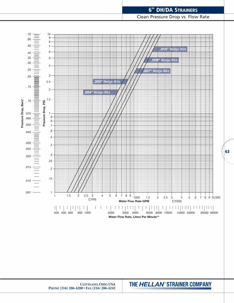
1 1.5 2 2.5 3 4 5 6 7 8 91000 1.5 2 2.5 3 4 5 6 7 8 9
Water Flow Rate GPM
Pre
ssur
e D
rop
, PS
I
1098
7
6
5
4
3
2.5
2
1.5
.015" Wedge-Wire
.009" Wedge-Wire
.007" Wedge-Wire
.005" Wedge-Wire
.004" Wedge-Wire
.70
Pre
ssur
e D
rop
, Bar
s*
.60
.50
.40
.35
.30
.25
.20
.15
.10
.070
.060
.050
.040
.030
.025
.020
.015
.010
.007
20001000 3000 6000 80004000 10000500 600 800400 15000 20000 30000 38000Water Flow Rate, Liters Per Minute**
(×100)(×1000)
10,000
1.9.8
.7
.6
.5
.4
.3
.25
.2
.15
.1
63
6" DH/DA STRAINERSClean Pressure Drop vs. Flow Rate
CLEVELAND, OHIO USAPHONE (216) 206-4200 • FAX (216) 206-4242
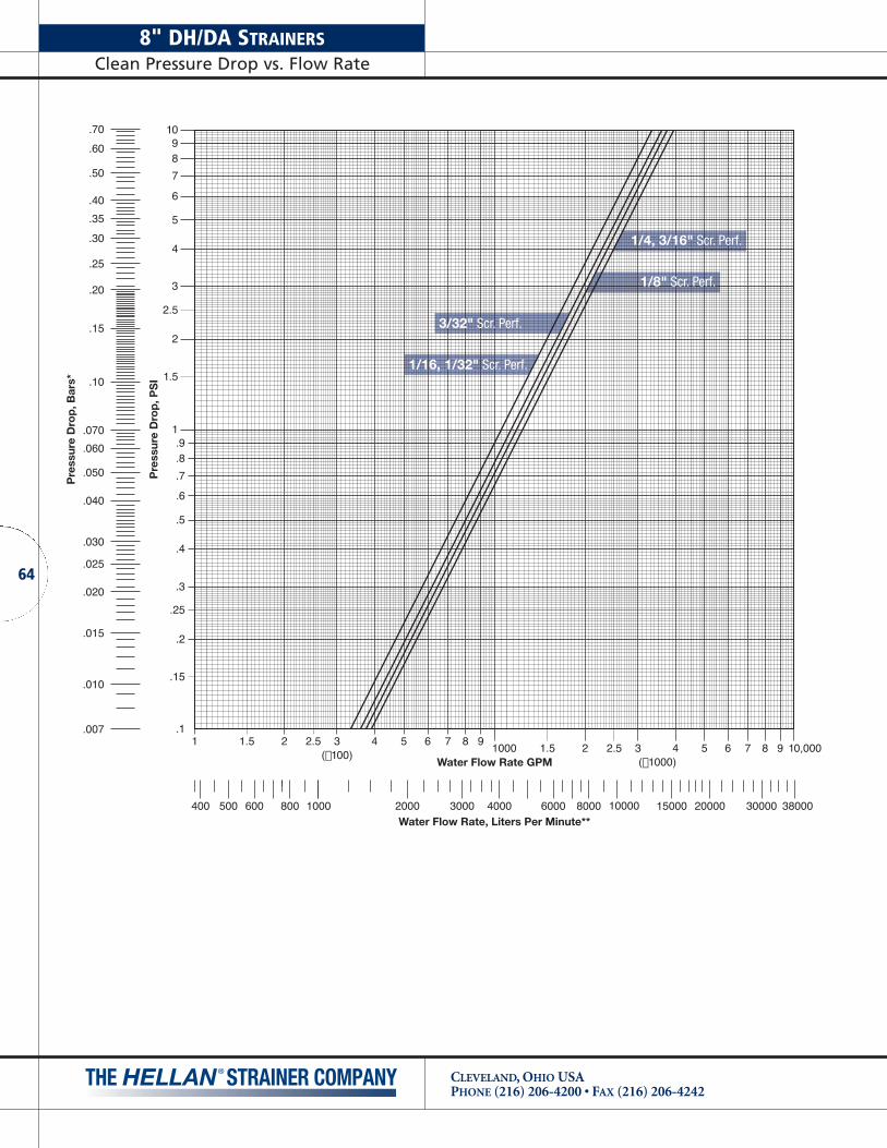
8" DH/DA STRAINERSClean Pressure Drop vs. Flow Rate
CLEVELAND, OHIO USAPHONE (216) 206-4200 • FAX (216) 206-4242
64
1 1.5 2 2.5 3 4 5 6 7 8 91000 1.5 2 2.5 3 4 5 6 7 8 9
Water Flow Rate GPM
Pre
ssur
e D
rop
, PS
I
1098
7
6
5
4
3
2.5
2
1.5
.70
Pre
ssur
e D
rop
, Bar
s*
.60
.50
.40
.35
.30
.25
.20
.15
.10
.070
.060
.050
.040
.030
.025
.020
.015
.010
.007
20001000 3000 6000 80004000 10000500 600 800400 15000 20000 30000 38000Water Flow Rate, Liters Per Minute**
1/4, 3/16" Scr. Perf.
1/8" Scr. Perf.
1/16, 1/32" Scr. Perf.
3/32" Scr. Perf.
(×100)(×1000)
10,000
1.9.8
.7
.6
.5
.4
.3
.25
.2
.15
.1

1 1.5 2 2.5 3 4 5 6 7 8 91000 1.5 2 2.5 3 4 5 6 7 8 9
Water Flow Rate GPM
Pre
ssur
e D
rop
, PS
I
1098
7
6
5
4
3
2.5
2
1.5
.015" Wedge-Wire
.009" Wedge-Wire
.007" Wedge-Wire
.005" Wedge-Wire
.004" Wedge-Wire
.70
Pre
ssur
e D
rop
, Bar
s*
.60
.50
.40
.35
.30
.25
.20
.15
.10
.070
.060
.050
.040
.030
.025
.020
.015
.010
.007
20001000 3000 6000 80004000 10000500 600 800400 15000 20000 30000 38000Water Flow Rate, Liters Per Minute**
(×100)(×1000)
10,000
1.9.8
.7
.6
.5
.4
.3
.25
.2
.15
.1
65
8" DH/DA STRAINERSClean Pressure Drop vs. Flow Rate
CLEVELAND, OHIO USAPHONE (216) 206-4200 • FAX (216) 206-4242

10" DH/DA STRAINERSClean Pressure Drop vs. Flow Rate
CLEVELAND, OHIO USAPHONE (216) 206-4200 • FAX (216) 206-4242
66
1 1.5 2 2.5 3 4 5 6 7 8 91000 1.5 2 2.5 3 4 5 6 7 8 9
Water Flow Rate GPM
Pre
ssur
e D
rop
, PS
I
1098
7
6
5
4
3
2.5
2
1.5
1/4, 3/16" Scr. Perf.
1/8" Scr. Perf.
1/16, 1/32" Scr. Perf.
3/32" Scr. Perf.
.70
Pre
ssur
e D
rop
, Bar
s*
.60
.50
.40
.35
.30
.25
.20
.15
.10
.070
.060
.050
.040
.030
.025
.020
.015
.010
.007
20001000 3000 6000 80004000 10000500 600 800400 15000 20000 30000 38000Water Flow Rate, Liters Per Minute**
(×100)(×1000)
10,000
1.9.8
.7
.6
.5
.4
.3
.25
.2
.15
.1

1 1.5 2 2.5 3 4 5 6 7 8 91000 1.5 2 2.5 3 4 5 6 7 8 9
Water Flow Rate GPM
Pre
ssur
e D
rop
, PS
I
1098
7
6
5
4
3
2.5
2
1.5
.015" Wedge-Wire
.009" Wedge-Wire
.007" Wedge-Wire
.005" Wedge-Wire
.004" Wedge-Wire
.70
Pre
ssur
e D
rop
, Bar
s*
.60
.50
.40
.35
.30
.25
.20
.15
.10
.070
.060
.050
.040
.030
.025
.020
.015
.010
.007
20001000 3000 6000 80004000 10000500 600 800400 15000 20000 30000 38000Water Flow Rate, Liters Per Minute**
(×100)(×1000)
10,000
1.9.8
.7
.6
.5
.4
.3
.25
.2
.15
.1
67
10" DH/DA STRAINERSClean Pressure Drop vs. Flow Rate
CLEVELAND, OHIO USAPHONE (216) 206-4200 • FAX (216) 206-4242

12" DH/DA STRAINERSClean Pressure Drop vs. Flow Rate
CLEVELAND, OHIO USAPHONE (216) 206-4200 • FAX (216) 206-4242
68
1 1.5 2 2.5 3 4 5 6 7 8 91000 1.5 2 2.5 3 4 5 6 7 8 9
Water Flow Rate GPM
Pre
ssur
e D
rop
, PS
I
1098
7
6
5
4
3
2.5
2
1.51/4, 3/16" Scr. Perf.
1/8" Scr. Perf.
1/16, 1/32" Scr. Perf.
3/32" Scr. Perf.
.70
Pre
ssur
e D
rop
, Bar
s*
.60
.50
.40
.35
.30
.25
.20
.15
.10
.070
.060
.050
.040
.030
.025
.020
.015
.010
.007
20001000 3000 6000 80004000 10000500 600 800400 15000 20000 30000 38000Water Flow Rate, Liters Per Minute**
(×100)(×1000)
10,000
1.9.8
.7
.6
.5
.4
.3
.25
.2
.15
.1

1 1.5 2 2.5 3 4 5 6 7 8 91000 1.5 2 2.5 3 4 5 6 7 8 9
Water Flow Rate GPM
Pre
ssur
e D
rop
, PS
I
1098
7
6
5
4
3
2.5
2
1.5
.015" Wedge-Wire
.009" Wedge-Wire
.007" Wedge-Wire
.005" Wedge-Wire
.004" Wedge-Wire
.70
Pre
ssur
e D
rop
, Bar
s*
.60
.50
.40
.35
.30
.25
.20
.15
.10
.070
.060
.050
.040
.030
.025
.020
.015
.010
.007
20001000 3000 6000 80004000 10000500 600 800400 15000 20000 30000 38000Water Flow Rate, Liters Per Minute**
(×100)(×1000)
10,000
1.9.8
.7
.6
.5
.4
.3
.25
.2
.15
.1
69
12" DH/DA STRAINERSClean Pressure Drop vs. Flow Rate
CLEVELAND, OHIO USAPHONE (216) 206-4200 • FAX (216) 206-4242

14" QH/QA STRAINERSClean Pressure Drop vs. Flow Rate
CLEVELAND, OHIO USAPHONE (216) 206-4200 • FAX (216) 206-4242
70
1 1.5 2 2.5 3 4 5 6 7 8 91000 1.5 2 2.5 3 4 5 6 7 8 9
Water Flow Rate GPM
Pre
ssur
e D
rop
, PS
I
1098
7
6
5
4
3
2.5
2
1.5
1/4, 3/16" Scr. Perf.
1/8" Scr. Perf.
1/16, 1/32" Scr. Perf.
3/32" Scr. Perf.
.70
Pre
ssur
e D
rop
, Bar
s*
.60
.50
.40
.35
.30
.25
.20
.15
.10
.070
.060
.050
.040
.030
.025
.020
.015
.010
.007
20001000 3000 6000 80004000 10000500 600 800400 15000 20000 30000 38000Water Flow Rate, Liters Per Minute**
(×100)(×1000)
10,000
1.9.8
.7
.6
.5
.4
.3
.25
.2
.15
.1

1 1.5 2 2.5 3 4 5 6 7 8 91000 1.5 2 2.5 3 4 5 6 7 8 9
Water Flow Rate GPM
Pre
ssur
e D
rop
, PS
I
1098
7
6
5
4
3
2.5
2
1.5
.015" Wedge-Wire
.009" Wedge-Wire
.007" Wedge-Wire
.005" Wedge-Wire
.002" Wedge-Wire
.70
Pre
ssur
e D
rop
, Bar
s*
.60
.50
.40
.35
.30
.25
.20
.15
.10
.070
.060
.050
.040
.030
.025
.020
.015
.010
.007
20001000 3000 6000 80004000 10000500 600 800400 15000 20000 30000 38000Water Flow Rate, Liters Per Minute**
(×100)(×1000)
10,000
1.9.8
.7
.6
.5
.4
.3
.25
.2
.15
.1
71
CLEVELAND, OHIO USAPHONE (216) 206-4200 • FAX (216) 206-4242
14" QH/QA STRAINERSClean Pressure Drop vs. Flow Rate

14"& 16" SA/WDA AND 16" QH/QA STRAINERSClean Pressure Drop vs. Flow Rate
CLEVELAND, OHIO USAPHONE (216) 206-4200 • FAX (216) 206-4242
72
1 1.5 2 2.5 3 4 5 6 7 8 910,000 1.5 2 2.5 3 4 5 6 7 8 9
Water Flow Rate GPM
rP
russer
D eI
SP ,
po
1098
7
6
5
4
3
2.5
2
1.5
1/4, 3/16" Scr. Perf.
1/8" Scr. Perf.
1/16, 1/32" Scr. Perf.
3/32" Scr. Perf.
.70
rP
ru sser
D e* sra
B ,p
o
.60
.50
.40
.35
.30
.25
.20
.15
.10
.070
.060
.050
.040
.030
.025
.020
.015
.010
.007
20001000 3000 6000 80004000 10000500 600 800400 15000 20000 30000 38000Water Flow Rate, Liters Per Minute**
(×1000)(×10,000)
100,000
1.9.8
.7
.6
.5
.4
.3
.25
.2
.15
.1

1 1.5 2 2.5 3 4 5 6 7 8 910,000 1.5 2 2.5 3 4 5 6 7 8 9
Water Flow Rate GPM
rP
russer
D eI
SP ,
po
1098
7
6
5
4
3
2.5
2
1.5
.015" Wedge-Wire
.009" Wedge-Wire
.007" Wedge-Wire
.005" Wedge-Wire
.004" Wedge-Wire
.70
rP
ru sser
D e* sra
B ,p
o
.60
.50
.40
.35
.30
.25
.20
.15
.10
.070
.060
.050
.040
.030
.025
.020
.015
.010
.007
20001000 3000 6000 80004000 10000500 600 800400 15000 20000 30000 38000Water Flow Rate, Liters Per Minute**
(×1000)(×10,000)
100,000
1.9.8
.7
.6
.5
.4
.3
.25
.2
.15
.1
73
14"& 16" SA/WDA AND 16" QH/QA STRAINERSClean Pressure Drop vs. Flow Rate
CLEVELAND, OHIO USAPHONE (216) 206-4200 • FAX (216) 206-4242

20" HH/AH AND 20" WDA STRAINERSClean Pressure Drop vs. Flow Rate
CLEVELAND, OHIO USAPHONE (216) 206-4200 • FAX (216) 206-4242
74
1 1.5 2 2.5 3 4 5 6 7 8 910,000 1.5 2 2.5 3 4 5 6 7 8 9
Water Flow Rate GPM
Pre
ssur
e D
rop
, PS
I
1098
7
6
5
4
3
2.5
2
1.5
1/4, 3/16" Scr. Perf.
1/8" Scr. Perf.
1/16, 1/32" Scr. Perf.
3/32" Scr. Perf.
.70
Pre
ssur
e D
rop
, Bar
s*
.60
.50
.40
.35
.30
.25
.20
.15
.10
.070
.060
.050
.040
.030
.025
.020
.015
.010
.007
2000010000 30000 60000 8000040000 1000006000 80004000 150000 200000 300000 380000Water Flow Rate, Liters Per Minute**
(×1000)(×10,000)
100,000
1.9.8
.7
.6
.5
.4
.3
.25
.2
.15
.1

1 1.5 2 2.5 3 4 5 6 7 8 910,000 1.5 2 2.5 3 4 5 6 7 8 9
Water Flow Rate GPM
Pre
ssur
e D
rop
, PS
I
1098
7
6
5
4
3
2.5
2
1.5
.70
Pre
ssur
e D
rop
, Bar
s*
.60
.50
.40
.35
.30
.25
.20
.15
.10
.070
.060
.050
.040
.030
.025
.020
.015
.010
.007
2000010000 30000 60000 8000040000 1000006000 80004000 150000 200000 300000 380000Water Flow Rate, Liters Per Minute**
(×1000)(×10,000)
100,000
1.9.8
.7
.6
.5
.4
.3
.25
.2
.15
.1
.015" Wedge-Wire
.009" Wedge-Wire
.007" Wedge-Wire
.005" Wedge-Wire
.004" Wedge-Wire
75
20" HH/AH AND 20" WDA STRAINERSClean Pressure Drop vs. Flow Rate
CLEVELAND, OHIO USAPHONE (216) 206-4200 • FAX (216) 206-4242

24" WDA STRAINERSClean Pressure Drop vs. Flow Rate
CLEVELAND, OHIO USAPHONE (216) 206-4200 • FAX (216) 206-4242
76
1 1.5 2 2.5 3 4 5 6 7 8 910,000 1.5 2 2.5 3 4 5 6 7 8 9
Water Flow Rate GPM
Pre
ssur
e D
rop
, PS
I
1098
7
6
5
4
3
2.5
2
1.5
1/4, 3/16" Scr. Perf.
1/8" Scr. Perf.
1/16, 1/32" Scr. Perf.
3/32" Scr. Perf.
.70
Pre
ssur
e D
rop
, Bar
s*
.60
.50
.40
.35
.30
.25
.20
.15
.10
.070
.060
.050
.040
.030
.025
.020
.015
.010
.007
2000010000 30000 60000 8000040000 1000006000 80004000 150000 200000 300000 380000Water Flow Rate, Liters Per Minute**
(×1000)(×10,000)
100,000
1.9.8
.7
.6
.5
.4
.3
.25
.2
.15
.1

1 1.5 2 2.5 3 4 5 6 7 8 910,000 1.5 2 2.5 3 4 5 6 7 8 9
Water Flow Rate GPM
Pre
ssur
e D
rop
, PS
I
1098
7
6
5
4
3
2.5
2
1.5
.70
Pre
ssur
e D
rop
, Bar
s*
.60
.50
.40
.35
.30
.25
.20
.15
.10
.070
.060
.050
.040
.030
.025
.020
.015
.010
.007
2000010000 30000 60000 8000040000 1000006000 80004000 150000 200000 300000 380000Water Flow Rate, Liters Per Minute**
.015" Wedge-Wire
.009" Wedge-Wire
.007" Wedge-Wire
.005" Wedge-Wire
.004" Wedge-Wire
(×1000)(×10,000)
100,000
1.9.8
.7
.6
.5
.4
.3
.25
.2
.15
.1
77
24" WDA STRAINERSClean Pressure Drop vs. Flow Rate
CLEVELAND, OHIO USAPHONE (216) 206-4200 • FAX (216) 206-4242

30" WDA STRAINERSClean Pressure Drop vs. Flow Rate
CLEVELAND, OHIO USAPHONE (216) 206-4200 • FAX (216) 206-4242
78
1 1.5 2 2.5 3 4 5 6 7 8 910,000 1.5 2 2.5 3 4 5 6 7 8 9
Water Flow Rate GPM
Pre
ssur
e D
rop
, PS
I
1098
7
6
5
4
3
2.5
2
1.5
1/4, 3/16" Scr. Perf.
1/8" Scr. Perf.
1/16, 1/32" Scr. Perf.
3/32" Scr. Perf.
.70
Pre
ssur
e D
rop
, Bar
s*
.60
.50
.40
.35
.30
.25
.20
.15
.10
.070
.060
.050
.040
.030
.025
.020
.015
.010
.007
2000010000 30000 60000 8000040000 1000006000 80004000 150000 200000 300000 380000Water Flow Rate, Liters Per Minute**
(×1000)(×10,000)
100,000
1.9.8
.7
.6
.5
.4
.3
.25
.2
.15
.1

1 1.5 2 2.5 3 4 5 6 7 8 910,000 1.5 2 2.5 3 4 5 6 7 8 9
Water Flow Rate GPM
Pre
ssur
e D
rop
, PS
I
1098
7
6
5
4
3
2.5
2
1.5
.70
Pre
ssur
e D
rop
, Bar
s*
.60
.50
.40
.35
.30
.25
.20
.15
.10
.070
.060
.050
.040
.030
.025
.020
.015
.010
.007
2000010000 30000 60000 8000040000 1000006000 80004000 150000 200000 300000 380000Water Flow Rate, Liters Per Minute**
.015" Wedge-Wire
.009" Wedge-Wire
.007" Wedge-Wire
.005" Wedge-Wire
.004" Wedge-Wire
(×1000)(×10,000)
100,000
1.9.8
.7
.6
.5
.4
.3
.25
.2
.15
.1
79
30" WDA STRAINERSClean Pressure Drop vs. Flow Rate
CLEVELAND, OHIO USAPHONE (216) 206-4200 • FAX (216) 206-4242

CLEVELAND, OHIO USAPHONE (216) 206-4200 • FAX (216) 206-4242
80
SPECIFYING A MODEL NUMBER
CHART A – STRAINER SIZE
Flow Rate Pipe Part No. (GPM) Size Code
95 1-1/2" 015
95 2" 020
160 2-1/2" 025
235 3" 030
360 4" 040
880 6" 060
1450 8" 080
2075 10" 100
2750 12" 120
4100 14" 140
5300 16" 160
8250 20" 200
10650 24" 240
16650 30" 300
(See page 11-12 for information on selecting size.)
CHART B – FLANGE TYPE
Flange Available Part No. Type Materials Code
Class 125 Flat Face Cast Iron 1
Class 250 Raised Face Cast Iron 2
Class 150 Raised or Steel, StainlessFlat Face Steel and Bronze 3
Class 300 Steel, Stainless Steel and Bronze 4
NPT Threaded Cast Iron TCast SteelCast Stainless Steel
Note: Contact the factory for information on flange types not listed above.
(See page 12 for information on flange selection.)
CHART C – BODY STYLE
Body Part No. Style CodeAngled Flow, Single Screen A
In-Line Flow, Dual Screens D
In-Line Flow, Quad Screens Q
In-Line Flow, Six Screens H
In-Line Flow, Single Screen S
Welded, Single Screen WS
Welded, Dual Screens WD
(See pages 8-10 for information on availability of strainersin various types of operation methods.)
CHART D – METHOD OF OPERATION
Method of Part No. Operation Code
Manual (Handwheel) H
Automatic A
Note: Strainers with motorized option must be ordered with appropriate control panel.
See information on specifying control panel below.
(See pages 8-10 for information on availability of strainersin various types of operation methods.)
CHART E – MOTOR SPECIFICATIONS FORAUTOMATIC STRAINERS
(For Manual Strainers, enter a “-” in this portion)
Motor Part No. Option Code
230/460 VAC 50/60HZ, 3PH, TEFC 1
115/230 VAC 50/60HZ, 1PH, TEFC 2
230/460 VAC 50/60HZ, 3PH, NEMA 7 3
115/230 VAC 50/60HZ, 1PH, NEMA 7 4
Note: Contact the factory for information on motor options not listed above.
CHART F – SCREEN MATERIAL
Screen Part No. Material Code
316 Screen, Cast Iron Hub, Cast Iron Center Ring, Bronze End Ring 4
316 Stainless Steel, All Parts 5
Monel Screen, All Parts 6
Note: Contact the factory for information on screen materials not listed above.
A model number for a Hellan Strainer may be specified by utilizing the charts and information below:
SAMPLE MODEL NUMBER
0 8 0 1 D H - 4 0 4 0 0
Basic Construction Materials (Chart H)Screen Opening Size (Chart G)Screen Material (Chart F)Motor Type (Chart E)Operation (Chart D)Body Style (Chart C)Flange Type (Chart B)Size (Chart A)
CHART G – SCREEN OPENING SIZE OPTIONS
Screen Opening Part No. Size Code
Perforated Screen Options
1/32" 02
1/16" 04
3/32" 06
1/8" 08
3/16" 12
1/4" 16
Slot Width Part No. Size Code
Wedge-Wire Screen Options
.004"* A4
.005"* A5
.007" A7
.009" A9
.015" B5
* Consult factory for additional information.
(See page 11 for information on screen opening options.)
CHART H – BODY MATERIAL OPTIONS
Body Part No. Material Code
Cast Iron, ASTM A278 Class 30 00
Bronze, C-95800 01
Cast Stainless Steel, ASTM A351 CF8M 04
Cast Steel, ASTM A216 WCB 07
Carbon Steel, Weldment, ASTM A36 10
Note: Contact the factory for body material options and coatings and finishes not listed above.
(See page 14 for information on body material options.)

81
CLEVELAND, OHIO USAPHONE (216) 206-4200 • FAX (216) 206-4242
AUTOMATIC STRAINER CONTROLPanel Part Number
When ordering an automatic strainer, an appropriate control panel must also be ordered. Use the chart below to specify an appropriate part number for the control panel.
SAMPLE CONTROL PANEL PART NUMBER
S S P - C 2 D - P
Enclosure (Chart 3)Number of Motors (Chart 2)Voltage (Chart 1)
CHART 1 – CONTROL PANEL VOLTAGE OPTIONS
Control Panel Part No. Voltage Code
460 VAC 50/60 HZ, 3 PH A
230 VAC 50/60 HZ, 3 PH B
115 VAC 50/60 HZ, 1 PH C
Note: Contact the factory for information on control panel voltages not listed above.
CHART 2 – NUMBER OF MOTORSFOR CONTROL PANEL
Number of Part No. Motors Code
1 Motor 1
2 Motors 2
4 Motors 4
6 Motors 6
CHART 3 – CONTROL PANELENCLOSURE OPTIONS
Enclosure Part No. Type Code
NEMA 4X Polycarbonate D
NEMA 4X Stainless Steel C
Note: Contact the factory for control panel enclosure options not listed above.

SAMPLES OF STANDARD SPECIFICATION
CLEVELAND, OHIO USAPHONE (216) 206-4200 • FAX (216) 206-4242
82
HELLAN MANUAL STRAINERS
The strainer shall be a _____" manual type employing _____cylindrical straining screens of the peripheral inflow design.The straining screens shall have _____" round perforations orwedgewire _____" slots and be of Type 316 Stainless Steelmaterial. Adjustable rigid scraper bars or brushes shall bemounted adjacent to the screens to accommodate scrapping of accumulated solids from the screens when the strainingscreens are rotated by means of a handwheel during a cleaningcycle. Removal of an inspection cover shall give access to thescraper bar or brush for inspection and adjustment and shallnot require the disassembly of the strainer to accomplish those tasks.
The strainer shall also have a sump for storage of strainedsolids. A flush valve installed on the sump by others shall beused to flush solids from the strainer during cleaning cycles.
The strainer body shall be of cast or fabricated steel ASTM _____ and have integral, in-line _____" inlet, and outlet flanges. Flanges shall be ANSI class _____.
The assembled strainer shall be hydrostatically pressure testedto 1-1/2" times the maximum allowable working pressure for aperiod of 10 minutes.
The assembled strainer shall be painted with a high-qualityalkyd machinery enamel (gray color), Sherwin-Williams KemAqua 70P.
An adjustable pressure differential switch (optional) shall bemounted on the strainer and shall be used to initiate an alarmif the pressure drop reaches a predetermined set point.
The strainer shall be a Hellan Strainer manufactured by TheHellan Strainer Company, Cleveland, Ohio.
HELLAN AUTOMATIC STRAINERS
The strainer shall be a _____" automatic type employing_____ cylindrical straining screens of the peripheral inflowdesign. The straining screens shall have _____" round per -forations or wedgewire _____" slots and be of Type 316Stainless Steel material. Adjustable rigid scraper bars or brushes shall be mounted adjacent to the screens to accom -modate scraping of accumulated solids from the screens whenthe straining screens are rotated with an electric motor andsuitable gear reduction. Each motor shall be 1/3 to 2 horse-power (as required) _____ Volt, _____ Ph, _____ Hz, 1.15 SFClass “F” Insulation, TEFC, 56C-Face, Footless. Removal of aninspection cover shall give access to the scraper bar or brushfor inspection and adjustment and shall not require the disassembly of the strainer to accomplish those tasks.
The strainer shall also have a sump for storage of strainedsolids. One 1-1/4" ball valve on 1-1/2" & 2" strainers, one 1-1/2" ball valve on 2-1/2" & 3" strainers, two 2" ball valves on14" and 16" strainers, two 3" ball valves on 20" and 24" strainers and two 4” ball valves on 30" and 36" strainers.
The strainer body shall be of cast or fabricated _____ con-struction per ASTM _____ and have integral, in-line _____"inlet, and outlet flanges. Flanges shall be ANSI class _____.
The assembled strainer shall be hydrostatically pressure testedto 1-1/2 times the maximum allowable working pressure for aperiod of 10 minutes.
The assembled (cast construction) strainer shall be paintedwith a high-quality alkyd machinery enamel (gray color),Sherwin-Williams Kem Aqua 70P. Assembled strainer of fabricated construction will be painted with a white Devcon 253 Epoxy.
An electric control panel furnished by The Hellan StrainerCompany shall control the strainer cleaning cycle. The panelshall include all motor starters, control relays, fuse and over-load protection, control transformer, operation lights, etc., andshall be mounted in a NEMA 4X wall mounted polycarbonateenclosure equipped with a door disconnect switch. The controlpanel shall conform to current NEMA, NEC, and OSHA codesand regulations.
The strainer control panel shall be equipped with a pro -grammable solid state timer to initiate cleaning cycles at predetermined intervals, a hand/off/automatic selector switch,and a push-button for manual starting. An adjustable cycleduration timer shall also be furnished to allow for control ofthe cleaning cycle duration. An adjustable pressure differentialswitch shall be mounted on the strainer and shall be used toinitiate a cleaning cycle if the pressure drop reaches a predetermined set point.
The strainer shall be a Hellan Strainer manufactured by The Hellan Strainer Company, Cleveland, Ohio.
For assistance in selecting a strainer, or specifying a model, contact the Hellan sales department at 1-888-4-HELLAN.

83
NOTES
CLEVELAND, OHIO USAPHONE (216) 206-4200 • FAX (216) 206-4242

NOTES
CLEVELAND, OHIO USAPHONE (216) 206-4200 • FAX (216) 206-4242
84

85
CLEVELAND, OHIO USAPHONE (216) 206-4200 • FAX (216) 206-4242
NOTES

CLEVELAND, OHIO USAPHONE (216) 206-4200 • FAX (216) 206-4242
The Hellan Strainer Company
A Subsidiary of Industrial Manufacturing Company LLC
3249 East 80th Street
Cleveland, Ohio 44104 (USA)
Phone: 216/206-4200
Fax: 216/206-4242
Toll Free: 888-4-HELLAN
Web: www.hellanstrainer.com
Manufactured with quality in the United States
Protected under U.S. Patent
Printed in the United States
Revised 10/17 3M AA/WP