helmet-mounted symbology and stabilization concepts · symbology and stabilization concepts richard...
TRANSCRIPT

NASA C,',atractor Pe_,'_ 19_6S7 USAATCOM "rechn!t al _epor_ 94-A-(J21
Helmet-Mounted OisplaySymbology and StabilizationConcepts
Richard L. Newman
0__.,II,.
<Z=>
CONTRACT NAS2-13811Jur_e 1995
•t-'.v:3.',O' ,_",F.T'O3;; (._(._.v ,arc
Aerof,ll_h_clyi _un,i_',_ _irectorate',.1.3fill! "%.5,"J _A 940_,"-":'_'d
https://ntrs.nasa.gov/search.jsp?R=19960033220 2018-06-02T19:30:50+00:00Z

NASA Contractor Report 196697 USAATCOM Technical Report 94-A-021
Helmet-Mounted DisplaySymbology and StabilizationConcepts
Richard L. Newman
Crew SystemsP. O. Box 963
San Marcos, Texas 78667
Prepared forAmes Research CenterCONTRACT NAS2-13811June 1995
N,_t_q31 Aerc, r',3'_-_'is£_r:QS_ce ,&d'T'.ir ;$!ra; Ce
Ames Research CenterT./o"_tt _:.e _J C_ 9J.:_:-".'.;0'.;
A,,,":."rr..ard l,._p Co--T::_::
Aeroflightdynamics Directoratef_'e_t F_id C,,L _,:_.-.- ",'.(_C

CONTENTS
LIST OF FIGURES ........................................................................................................
LIST OF TABLES ..........................................................................................................
ABBREVIATIONS .......................................................................................................
POINTS OF CONTACT .................................................................................................
SUMMARY ....................................................................................................................
A BACKGROUND ...................................................................................................
f I ) Statement of the Problem .............................................................................
(2) The Real Problem ..........................................................................................
B PROBLEMS WITH VIRTUAL DISPLAYS ........................................................
( ! ) Lesson._ Learned from HUD Developments ...............................................
(2) Problem._ Unique to HMDs ..........................................................................
(3) Summary ........................................................................................................
C DEFINITIONS .......................................................................................................
(1) Frequently Used Terms ................................................................................
(2) Stabilization Terms .......................................................................................
D HMD SYSTEMS ..................................................................................................
(I) Operational and Developmental HMDs ......................................................
(2) Research I-IMDs ............................................................................................
(3) HMD Simulators ...........................................................................................
(4} Helicopter HUD Systems ............................................................................
E HMD SYMBOLOGY SUMMARY ......................................................................
( 1 ) Operational HMDs .......................................................................................
(2) Rotorcraft HMDs Under Development .......................................................
(3) Helicopter HUDs ...........................................................................................
(3) Proposed Fixed-Wing HMDs ......................................................................
F SYMBOLOGY STABILIZATION .......................................................................
( I ) General Comments .......................................................................................
(.2) Coordinate Systems ......................................................................................
(3) Symbol Orientation .......................................................................................
t4) Symbol Location ............................................................................................
Page
V
V
vii
xi
xiii
1
I
2
5
5
7
9
!!
II
12
13
13
14
15
17
17
18
21
21
33
33
33
34
34
iii

G HMD LESSONSLEARNED TO DATE .............................................................( 1 ) Training ..........................................................................................................
(2) Operations .....................................................................................................
(3) Research ........................................................................................................
(141 Observations ................................................................................................
H RESTATEMENT OF THE PROBLEM ..............................................................
THE HELMET-MOL'NTED DISPLAY DESIGN GUIDE .................................
(1) Previous Design Documents ........................................................................
(2) Strawman HMD Design Guide ...................................................................
(3) Database Development ................................................................................
POTENTIAL BENEFITS ......................................................................................
( l j Reduced Design Cost ...................................................................................
(2) Civil Operators ..............................................................................................
(3) MilitaQ' Operators ........................................................................................
(4) External Load Operations ...........................................................................
(5) Other Uses of HMDs ....................................................................................
K RESULTS AND RECOMMENDATIONS ..........................................................
(1) Results ...........................................................................................................
(2) Recommendations .........................................................................................
L REFERENCES ......................................................................................................
APPENDIX A: HUD/HMD GLOSSARY .....................................................................
(a) Optical Definitions ........................................................................................
(b) Symbology Definitions ..................................................................................
(c) Systems Definitions ......................................................................................
_'d) Weapons Definitions ....................................................................................
(e) Abbreviations ................................................................................................
APPENDIX B: HMD BIBI.IOGRAPHY ........................................................................
APPE="-DIX C: STRAWMAN HMD DESIGN GUIDE ............................................
39
39
39
40
41
43
45
45
46
48
51
51
51
51
52
52
53
53
53
55
_t
Ol
62
72
86
91
92
95
!0'7
iV
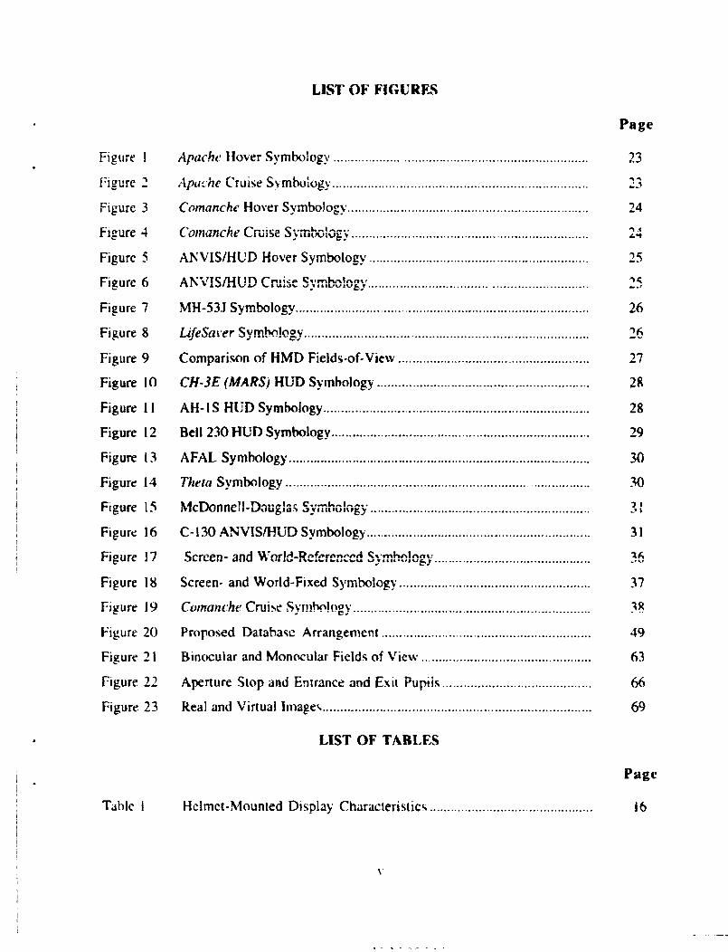
Figure 1
Figure 2
Figure 3
Figure 4
Figure 5
Figure 6
Figure 7
Figure 8
Figure 9
Figure If)
Figure 1 !
Figure 12
Figure 13
Figure 14
Figure 15
Figure 16
Figure 17
Figure 18
Figure 19
Figure 20
Figure 2 I
Figure 22
Figure 23
Tahle I
LIST OF FIGURES
Apache ltover Symbology. ......................................................................
Apac'he Cruise S_,,mbo;ogy. .......................................................................
Comanche Hover Symbology. ...................................................................
Comanche Cruise S,, mo,.,_,.,_:, ...................................................................
ANVIS/HUD Hover Symbology ..............................................................
ANVIS/HUD Cruise _,'-'_',-_".-,'
MH-53J Symbology ...................................................................................
LifeSaver Svmhrdoov
Comparison of FIMD Fields-of-View ......................................................
CH-3E (MARS) HUD Symbology ............................................................
AH- !S HUD Symboiogy ...........................................................................
Bell 230 HUD Syrnboiogy .........................................................................
AFAL Symboiogy .....................................................................................
Theta Symbology .....................................................................................
McDonnell-Dougla._ e..-,.._, ....o*J,lt,u,*,gy ..............................................................
C- 130 ANVIS/HUD Symbology ...............................................................
Scrcerl- arid 'Vt:'orlrl_l_,¢or_n,,,,_d _l'mF_l_nl:• w lttat, At tq,_l.-*_.,t*,..taq.*,..t.t _,Jet Jsst,q,,lt'_,,,y ............................. , ..............
Screen- and World-Fixed Symbology ......................................................
Comanche Cruise Sym._. !ogy. ..................................................................
Proposed Database Arrangement ...........................................................
Binocular and Monocular Fields of View. ...............................................
Aperture Stop and Entrance and Exit Pupiis ..........................................
Real and Virtual hnage_, ...........................................................................
LIST OF TABLF_
Helmet-Mounted Display Characteristics ..............................................
Page
23
24
/."t
25
26
26
27
28
28
29
30
30
2n
31
..__,
37
49
63
66
69
Page
16

A-TD/E
ACIDTEST
ADI
ADS
AI-:A[.
AFDD
AGARD
AH-IS
AH-64
AHP
ANVIS
ARI
ATC
C-130
CH-3E
CH-46E
CH-47
CONDOR
CRT
CSRDF
ELVIRA
EMI
EMS
F-4
F-16A
F/W
FAA
FLITE
FOHMD
Abbreviations
Military Fighter. Corxair Ii
Aircraft C_kpii '-_ ......................... " -"mLutmauoa ulspiay Teiae[g t_xpelt aystcm Too;
Attitude director indicator
Aeronautical r_.._. _..... ,_..._JJk, _l_ll OtailUdl U
Air Force Armstrong Laboratory
A:'roflightdynamics r_,,.,.,,_,,,,.,..,,,._ ,.,, ..,.
Advisory Group for Aeronautic,, Research and Development
Militar)" Helicopter. Cubra
Military Helicopter, Apache
Advanced Helicopter Pilotage
Aviator's Night Vision System
Army Research Institute
Air traffic control
Military Transport. Hercules
- IL.
Military. Helicopter. Ju,,, G_er_ u,,,,"'"....
Military Helicopter. Sea Knight
Military Hel,cop,,.,.• _lal|llllf_./It.
Covert Night/Day Operations in Rotorcraft
Cathode ray tube
Crew Station Research and Development Facility
Extremely Low Visibility Rotorcraft Approache_
Electromagnetic interii:rence
Emergency Medical Service
blilitary Fighter. Phantom
Militar) ° Fighter, Fighting Falcon
Fixed-wing
Fedc:al Aviation Administration
Flight Laboratory for Integrated Tes! a_d E:"J!':'.','i,J_
Fiber Optic Helmet-Mounled Di.,,play
vii

FOR
FOV
FPM
FSWG
HDD
FtIDSS
HMD
HSI
HUD
IFR
IHADSS
IP
IPD
1R
LOS
MARS
MD-80
MH-531
NAH-]
NASA
NAWCAD
NOE
NVD
NVG
PC
R/W
RAH-66
RASCAL
RPM
SCTB
SPIRIT
Field-of-regard
Field-of-view
Flight path marker
Flight SymN-_logy Working Group
Head-down di,_play
Helmet Integrated Display e:r.,..:._ c ........
Head-/helmet-mounted display
Horizontal " "'" '_ mx'_"'MtU.,IO,, _,. t""J
Head-up display
lnstrun_ent flight rules
Integrated Helmet and Display Sighting System
Instructor pilot
Interpupilary distance
Infrared
Linc-of-._ight
Mid-Air Retrieval System
Civilian Transport
Military Helicopter. Sea Dragmr
f-, .... ..Experimental Helicopter. t,,b,,,
National Aeronautics and Space Administration
Naval Air Warfare C,_.... ,, ,,,,,.,,,,,_; ...... r, ,.,,rx"•,_,,,,,:';...
Nap-of-the-earth
Night vision device
Night vision goggles
Personal computer tlBM compatible)
Rotary -wing
Military Helicopte.-. Comanche
Rotorc raft A ircrew-Sy _tems Concepts Airborne Laboratory
Revolutions per minute
Simulator Complexity Te_ "ocu-_
Simulation Program for Improved Rotorcraft Integration Technolog_
viii

TLAR
U[I- IN
UH-60
LK
I;S
[;SAF
USASC
Thai looks about right.
Military Helicopter. Huev
Military llelicopter. Blackhawk
United Kingdom
United States
US Air Force
US Army Safety Center
ix

Points of Contact
Durnng the course of the Phase 1 study, the following organizations and individuals wcre
contacted. Some of the contacts occurred during professional meetings and symposia.
Advanced Aviation ConceptsMr. Richard Adam_
2 AirMelhod.,,
Capt. Leru/Jackson
Capt. Andy Mt.John.,,ton
Boeing Helicopter
Mr. Ryan Wilkins
4 CAE Electronics
Dr. Ronald Kruk
l=_der_i Aviation Administration
Mr. Peter Hwoschinsky
Mr. Paul Erway
Mr. Stephen Hickok
Dr. GarD' Headley
Flight. Visions
Mr. Mark PhillipsMr. Herb White
Mr. Steve Brown
Mr. Robin Sleight
8 Hob Aeronautic.',
Mr. Roger Hoh
9 Honeywell
Mr. Robert North
Mr. Jeff Radke
10 Kaiser El¢f;tronic_,
Mr. Joseph Garcia
!1 pet roleutq..H.clicootersMr. Vern All.r1
xi

12
13
14
15
16
17
18
Research Trianele Park
Mr. Malcolm Burgess
Sextant Avionioue
Mr. Luc Baron
Dr. Main Leger
Mr. Roger Parug
Sikorsky
Mr. Nick LapposMr. Robert Warren
STC Corporation
Dr. Donald Richardson
US Air Force tWright-Patterson AFB)
Mr. Eric Geiselman <University of Dayton1.Mr. Dean Kocian
S/L Robert Munns
Dr. Robert Osgood
US Army iForl Rucker)CW3 John Armbrust
CW2 Neil Caldwell
CW2 Rick KorycinskiCW3 Steven Paris
Cpt Douglas Sperandio
US Army (Fort Bc;voir}
Maj Brian Giilcspie
US Navy/Marine Corp. _ (Patuxent NAS]
ldC And)' Lahaszow
Mt

Stlmnmr_'
The helmet-mounted display (HMD) presents flight, sensor, and weapon information in the
pilot's line of sight. "l'he HMD was developed to allow the pilot to retain aircraft and weapon
information and to view sensor images while looking off boresight.
The only operational helicopter ltMD system today is installed in the Apache. This system
incorporates a movable infrared sensor which is slaved to the pilot's line of sight. The sensor
image is shown on the HMD reticle with symbology embedded in the image. The system was
developed to allow contact flight at night. While Apache system meets this design objective.
the combination of sensor image and symbology can be confusing and present misleading
flight information.
The pre,w.nt study reviewed the current state-of-the-art in HMDs and identified a number of
iss_tes r:i_plying to HMDs. Several are identical to Head-Up Display (HUD) issues: symbol
standardization, excessive clutter, and the need for integration with other cockpit displays
and controls. Other issues are unique to the head-mounted display: symbol stabilization,
inadequate definitions, undefined symbol drive laws, helmet considerations, and field-of-view
(FOV) vs. resolution tradeoff requirements.
In particular, symbol stabilization is a key issue fGr HMDs. In addition to requiring further
experimental studies, it was found to impact the definition and control law issues. Pan of the
problem is there is no agreed upon _t of definitions or descriptions for how HMD symbols
are driven to compensate for pilot head motion. A candidate set of definitions is proposed toaddress this.
Symbol stabilization is critical. In the case of the Apavhe helicopter, the lack of compensa:ion
for pilot head motion creates excessive workload during hovering and nap-of-the-earth I'NOE)
flight. This high workload translates into excessive training requirements. At the same time.
misleading symbology makes interpretation of the height of c_herp.tr'tinng irnnnc;¢ihlP
The underlying eau_ is inadequate of design criteria for HMDs. "l'he existing military"
standard does not reflect the current state of technology. In addition, there are generally
inadequate test and evaluation guidelines. The situation parallels the state-of-the-art for
HUDs several years ago. The major recomnaendation of this study is the development of an
llMD design guide similar to the HUD design guide. A further recommendation calls for thecreation of a HMD database in electronic format.
There are several specific areas v, here additional simulatien and flight experiments are
needed. These include development of hover and NOE sytnbology which compensates for
pilot head movement and the tradeoff between FOV. sensor resolution and symbology.
xiii

HELIqET-MOUNTED DISPLAY
FLIGHT 8YI_OLOG¥ _ BTABILIZATION CONC]EPT8
A m&CI_GROUND
Virtual image displays present collimated flight symDology and
sensor images (infrared, radar, etc.) in the pilot's view of the
world. This allows simultaneous viewing of flight information,
sensor information, and the real world. These displays come intwo varieties: head-up displays (HUDs) and helmet-mounted dis-
plays (HMDs).
HUDs are fixed displays usually mounted at the top of the instru-
ment panel. HUDs are becoming the primary fixed-wing flight ref-
erence for use during both visual and instrument meteorologicalconditions. HMDs were developed to accommodate the need for
larger field-of-regard (i. e. to look off boresight).
These displays allow presentation of flight-critical information
in a variety of new and useful formats and can combine the infor-
mation from a large number of sources. This can be both a bless-ing and a curse.
HMDS offer many advantages in terms of weapon delivery and maneu-
vering in close proximity to obstacles. They offer advantages in
terms of weapon delivery and maneuvering in close proximity toobstacles. At the same time, HMDs present many significant chal-lenges which must be addressed.
As the technology matures, HMDs will be found on more aircraft.
At this time, HMDs are found on one operational aircraft (AH-64,
Apache), although there are a number of candidate systems beingproposed.
(1) _tat.ement of the Pr.-bl-.m-
The present standard for the HMD describes the symbology for theApache(1). This standard represented the best information availa-
ble at the time of its publication in 1984, but has not kept upwith the technology.
In the Apache, the symbology does not compensate for pilot head
motion. There have been difficulties reported with this symbol-
ogy, both in terms of mission degradation and in terms of exces-sive training costs. In addition, the use of non head-tracked
horizon information can result in a flight hazard. For these rea-
sons, a new standard should be prepared. The Aercflightdynamics

Directorate (AFDD) is preparing an Aeronautical Design Standard
(ADS) to address these topics.
(2) The Real Problem_
The real problem is not so much with the existing standard, rath-
er it is an indictment of the display design process. The devel-
opment of most electronic flight displays does not follow a con-
sistent and logical path. Rather the display formats are devel-
oped using a "That looks about right" (TLAR) approach.
The display complexity can be looked at as a global _o specifichierarchy: at the top, we can consider the general informational
requirements, followed by overall systems issues. As we move down
the hierarchy, issues be come more specific, first arrangement
and dynamics of the display, then the icons, and finally the de-tails of the icons. Most symbology development heretofore has
concentrated on the bottom end -- defining the icons.
The most important aspect of display design, in our opinion, determining theinformation requirements has relied on the use of expert pilot opinion.Traditionally, display designers have sought pilot opinion for guidance during thedevelopment of new flight displays. While user input is helpful, I)ilots tend to havediverse (and strongly held) opinions. In addition, pilots with limited background indisplay evaluation often limit the design of novel systems to those concepts withwhich the', are familiar (i. e., ¢LAR).
This would be an acceptable, if inefficient, desiqn methodologyif there were valid test criteria and a well-developed test pro-
tocol. Unfortunately, neither has been in place. Recently a de-
sign handbook has been developed for head-up displays(2). A simi-lar procedure should be developed for MMDs as well.
The display design must consider why the pilot needs the data and what the pilotis expected to do with the data. According to Singleton (33, a number of questionsshould be considered durir=g the development of a display:
o Does the pilot's need justify the display?
o What data does the pilot need that has not been provided?
o Can the average pilo'_ 0b',ain ,,,ha, =_ ,=_,;,o_ oo_;m,,_I_flgL IV 1_4glCQ_d _q_lly
o Does the display conform ...• to the real world?• to other cockpit displays?• with previous pilot habits and skills?• with required decisions and actions?(_3)
The development of any display must start with the basic principle of analyzing themission requirements.The information required by the pilot and crew must becataloged. Only then can the clisplav syrnbology be designed. Head-downi_strurnents did not change greatly for many years. As a result, designers forgotthis basic principle and concentrated on matchir, g the format of the "basic T."

The final see of questions concerning conformity should not be taken as anabsolute requirement for duplicating previous displays or the real world. Rather, itmeans that the display should not be in conflict with the pilot's experience andtraining nor with the external cues. It would be foolish to insist that BUDS ond._g:)s conform exactly to early round-dial instrumsnts or electronic head-down
displays.
fn 1969, Ketchel and Jenney studied the requirements for electronic displays(__).While their study is technologically dated, the underlying principles of determiningthe information requirements are still valid today. Their report covered informationrequirements, symbology design, ano display characteristics.
Newman prepared a design handL_k for head-up displays which de-
scribes a design methodology, presents specific design criteria,and outlines evaluation criteria(2). Thi_ handbook also lists the
"lessons learned" from a history of HUD symbology.
Following completion of the display design, its evaluation must be based onobjective, performance based criteria and measures of the disptay's effect onmission performance. It is up to the evaluation team to determine what appropriateflight tasks and performance measures are. These should reflect the intended mis-sign of the aircraft and must include all mission segments.

(x)
(a)
(b)
(c)
B PROBLFd_ WITH VIRT._%L D_'_'L%Y_
_ossons _earned from RUD Develo=ments
8_I Stanaardisation: Wzth any electronic aircraft dis-
play, head-up, head-down, cr helmet-mounted, there are two
divergent forces. On the one hand, there is a great clamor
for standardization of symbology. At the same time, there is
an extraordinary desire to make every aircraft application
different. Any student of head-up display (HUD) history will
testify to this.
"It £= a most interesting fact that one of the
first things a pilot exhiDits on being _xposed
to MUD flying is an inQatiable drive to redesign
it in his/her own h_age. It border8 on • rell-
gious experlence."(_)
HUDs are see-through, virtual image displays. As such, they
are fundamentally different from panel mounted displays. In
spite of the differences, HUD symbology often mimics head-
down displays. This has resulted in confusion over control
techniques, in excessively cluttered displays, and in dis-
plays which do not make the best use of the HUD.
Similarly, some proposed _D symbology formats appear to be
copied inappropriately from HUD symbologies.
Lack of Crlteris: What has been lacking is any organized set
of development, test, and evaluation criteria for displays.
As a result, HUD development usually progress through a se-
ries of personal preference choices by either the manufac-
turer's project pilot or the customer's pilot.
As decisions are made, the rationale for the choices aren't
documented. This forces new systems to go through the same
process time and again.
_: One of the primary goals for a see-through display
is to present the pilot an uncluttered display. Since the
pilot will necessarily being looking through a HUD to view
the real world, there is an paramount requi-ement te mini-
mize display clutter. Both Newman(_) and Hughes(Z) emphasize
this. Hughes expressed this principle that not one pixel should be
lit unless it "buys" its way onto the screen by providing a
demonstrable improvement in performance(_)_*
This issue may be more pronounced If a raster sensor image
is displayed in conjunction with stroke symbols. No criteria
have been generated dealing with raster/symbology combina-
tions.
This has been referred e_ =¢ .=_v=_,=,= v=;._i.1=

(d)
(o)
(f)
8ymh_l Control Laws: HUD control laws and a!gcrithms whichdrive the various symbols have not been well described. The
absence of specifications and of documentation has created
problems with HD_s where the symbols were excessively noisy(lateral motion of the F-16A FPM) or led to pilot uncertain-
ty about the origin of the data (aircraft reference symbol
in the MD-80).
Historically_ there have been no requirements to deliver the
display code as part of the data package. This makes it
quite difficult to determine exactly what is displayed and
how the symbols are driven° Manufacturers treat the source
code as proprietary data. The only algorithms publiclyavailable, to our knowledge, are for the A-TD/E HUD. (Z) The
USAF has attempted to "reverse engineer" the F-16A symbol
generator code. This problem has been described previous-
ly(_).
7_dKqhqEL_LO_: Many WUDs are installed as "add-ons." If inade-
quate attention is paid to integrating the MUD with existing
systems, excessive pilot workload can result. This may not
be apparent in most situations, b_t can become overwhelmingwith a small addition to external workload. In a recent
flight test(_), poor system integration did not become ap-parent until operational trlals. The difference between var-
ious ATC workloads resulted An a display being rated as"satisfactory" during low workload situations and "unaccep-
table" when, for example, the pilot was asked to "maintain
180 knots to the marker" and vectored through the localizer
before final intercept.
8oftw_;e Welidation: A major constraint is the need to vali-
date the software which performs the algorithms driving thesymbols. This can require a considerable amount of time. Us-
ually the validation is well underway before the disp!ayevaluation is begun. As a result, there is an extreme reluc-
tance %o modify any symbol or control law since it will re-
quire revalidation and a large increase in cost. It can be
said that there is no such thing as °'changing one line ofcode."
The display symbology thus becomes "frozen" before test and
evaluation. It As expensive to change even a manor item,
such as the shape of a symbol, not because of the effort to
make the change, but because of the lengthy validation andverification of the software.

(2)
(a)
.P.roblems UniQ-J8 to mr_Q
pvmbol Stabilization: HMDs present unique symbology problemsnot found in MUDs. Foremost among these is the issue of
maintaining spatial orientation of the synbols. All previous
flight displays, round dial instruments, HDDs, and HUDs,
have been fixed in the cockpit. With the HMD, the flight
display can move through a large _ngle. If improperly imple-mented, this can lead the pilot _nto incorrect control in-
puts or aggravate spatial disorientation.
As an example of these problems, the Apache hover symbology
is presented as a "God's eye" view of the helicopter(l_Q).The aircraft's velocity is shown as a vector indicating its
drift over the ground. This symbology is not stabilized with
respect to the aircraft, but is fixed in the display field-of-view (FOr). Thus, when the pilot looks to the side, he
must mentally perform two coordinate rotations -- one to ro-
tate the display from the side to the forward direction andone to rotate it from the forward view to the vertical
(plan) view.
Additionally, the raster image from the infrared (IR) camera
is shown as a "pilot's eye" view. This awkward combinationof coordinates tends to make orientation difficult and leads
to excessive training requirements.
The HMD is not a MUD with a large field-of-view. In additionto the three degrees of freedom for the MUD (the three air-
craft axes), the HMD has three more (two for LOS direction
and one for head tilt).
(b) Lack of Deflnlt_oDs: Many of the terms used in HMD studieshave not been well defined. We need to have a common lan-
guage to ensure that system descriptions are communicated.
As an example, the term "stabilized" has been widely used
with two meanings. "Roll-stabilized" has been used to mean a
symbol which rotates to indicate the roll or bank of theaircraft. "World-stabilized" and "head-stabilized" have both
been used to indicate symbols which move to remain fixed
with respect to external objects.
(c) __ymbol Drive Laws: The symbols drive algorithms for elec-
tronic displays are an integral part of the description. As
with HUDs, the laws themselves and the assumptions used in
their development have not been documented. This problem ismore crlZical with HMDs since the motion of the symbols is
affected by head movement as well aa aircraft movement. Dur-
ing the course of this study, reviews of HMD symbologies
were hampered by poor or nonexistent descriptions of symbolmotion.
(d)
(e)
Keener considerations: The need to place the display on thepilot's head creates a design goal of minimizing head-borne
weight. While the weight is important, the location of the
helmet center-of-gravity is also important. This problem may
be more critical for aircraft equipped with ejection seats
than for helicopters.
The helmet must, of necessity, be attached to the aircraft
via cables. Both power to the display and image/symbology
signals must be transmitted. At present, the most critical
installation type would be a binocular CRT system which re-
quires high voltage power supplies and separate signal in-
puts. Cabling must be shielded to prevent electromagnetic
interference (EM!) and, at the same time, be flexible enoughnot to interfere with pilot head movement.
The helmet position must be tracked with respect to the di-
rection of the pilot's line-of-slght (LOS) and head-tilt.
Both infrared (iR) trackers and magnetic trackers have been
used. The trackers (used in the Apache) use a IR beam re-
flected off the helmet to track pilot LOS. IR trackers gen-erally do not account for head-tilt. Magnetic huad trackers
follow a source on the helmet and generally sense head-tilt.Both systems require helmet modifications.
Field-of-Vlew II_pss (Per|: The issue of how wide should thefleld-of-view (FOV) be for HMDs is unresolved. One of the
arguments against the use of night vision goggles (NVGs) is
the narrow FOV which blocks the pilot's use of peripheralvision cues_
Experiments are planned using the Flight Laboratory for In-
tegrated Test and Evaluation (FLITE) research vehicle to de-termine how much FOV is required for unaided vision. This
experiment will present restricted FOV visors and measure
pilot performance. While this will be true for unaided vis-
ion, one must be careful in interpreting the results. Mostsensors will limit the resolution. While it seems clear that
there will be a trade-off between resolution and FOV, whatthe tradeoff is not at all certain.
Further, symbology can assist the pilot in overcoming re-
stricted FOV. For example, it would be difficult for a pilot
to land an airplane looking through the same For is a typi-
cal MUD. Yet with symbology along, the pilot can land moreprecisely than with an unrestricted FOV.
These issues require resolution (pun intended).
8

(f) _L_KJL_gA: Another issue is the effect of raster image
accuracy on viewing real-world images and symbology. In par-ticulsr, the fairly large eye-sensor distance for the Apache
creates mis-reglstration for close objects viewed ninety de-
grees off-axls. This mls-registration may have implications
for symbology choices. If there is mis-registratlon, shouldthe s_bology be changed from what it would be in the idealcase?
(g) Monocular vs. BI-Q_,L]JU:: Many workers have implicitly as-
sumed that bi-ocu'_r HMDs are superior to monocular simply
because they are more complicated. In fact, pilots report
(anecdotally) some advantages to monocular HMDs. To date,
thi& has not been studied and performance/cost trade-offdata obtained.
(h) Advancs_ _G Consi_eratlons: Similarly, many researchers as-
sume that future HMDs will have some form of symbology fixed
with respect to the real world and that head-trackers willa11ow both imagery and symbology to move and compensate for
pilot head motion. This may not be true. There ham been aninterest in incorporating flight and other symbology into
advanced night vision goggles (NVGs). If 8ymbology could be
merged with the NVG images and be mission effective, such
symbol-enhanced NVGs could prove to be considerable benefit
to helicopter pilots and serve as low-cost HMDs.
The point of this discussion is that there may be a placefor symbology fixed on the HMD screen as an adaptation of
the NVG. The adaptation of symbology to the Aviator's Night
Vision System (Ah_IS/_UD) is an example of such a system.Care must be taken, however, since many of the deficiencies
in the Apacha symbology apply to the AN_IS/HUD or other ad-
vanced NVG symbology.
(3} Summary
These are not trivial issues. They have not been fully resolved
for HUDs which have over 20 years of operational use. It would be
naive to think that HMDs, which are much more complex, will not
require some effort to avoid the same type of problems as have
been experience by HUD users over the years.

C DEFINXTION8
Before we can discuss stabillzation, optical, or other character-
istics of helmet-mounted displays, we need a common language. A
HUD Glossary was prepared as part of an earlier study (I_!1), and
has been extended to include HMD-related definitions (12). This
glossary is attached as Appendix A to this report.
(I) FZo_uentlv Used Terms
Some terms are used frequen x,i =_A_ _=u_x a+,_ _L_ _=_ ,=,=to aid the reader.
(a) BJ-o_lar BMD: A helmet-mounted display presenting the same
image to each eye.
Bi-ocular implies one sensor displaying to both eyes; _,,,_....-
ular implies a separate sensor for each eye.
(b) _: Vision using both eyes.
(o) Binocular B_ID: A helmet-mounted display presenting different
images to each eye.
(d) Conform41 DisPlay: A see-through display (HMD or HUD) in
which the symbols, when viewed through the m_D, appear to
overlie the objects they represent.
(e) Contact Analog: A dis ay .._.. _o a +._ ...................real world.
Note: a contact analog format need not be conformal.
(f) Field-of-Reaard (FOR_: The spatial angle in which a sensorcan view.
For helmet-mounted displays, the spatial angle in which the
display can present usable information.
(g) Field-gf-Viev (FOV): The spatial angle in which the symbol-
ogy can be displaye_ measured laterally and vertically.
(h) LiBg.gf Si0ht (LOS): A line from the pilot's or observer's
eyes in the direction of viewing.
(i) llevatioq Ladder: A set of reference symbols showing in-crements of angles to the horizon.
The term "elevation" is used to distinguish these angles
from pitch angles. Pitch angles apply to the attitude of the
aircraft about the lateral axis. Elevation applies to the
pilot's LOS and is used for directions away from the nose ofthe aircraft.
II

(k)
Fliubt Path Marker (rPM): The symbol showing the aircraft
velocity vector.
The difference between FPM and velocity vector is that the
FPM is projected along the forward view while the velocity
vector symbol may not (as in hover symbology). In addition,the FPM is used for direct aircraft control: while the velo-
city vector usually is not
Horlzon Line: A symbol indicating a horizontal reference or
zero pitch.
sowditch(13) defines several different horizons: the sensl-
ble horlzom (a horizontal plane passing through the eye of
the observer), the geoldal hozlzom (a horizontal plane tan-
gent with the geoid directly below the observer, the geomet-
rlaal horllom (the observer's LOS tangent to the geold), and
the _isible horisom (the demarcation between surface and
sky).
The difference between the geometrical horizon and the visi-
ble horizon is caused by atmospheric refraction and by theelevation of the terrain.
The difference between the sensible horizon and the visible
horizon is called the dip correction. This is not a problem
at typical helicopter altitudes. (At 100 ft, the dip correc-tion is 2.8 mr.) In addition, the sensible horizon is usual-
ly obscured by hills, trees, etc. making any discrepancy ir-relevant.
(2) 8tabilisa_om.T#rms
other terms dealing with symbol stabilization will be discussed
in Section F, beginning on page 33.

D _ SYSTEMS
Table i lists the optical and other characteristics of the vari-
ous helmet-mounted displays.
(_) ODvr_tlonal and De_Ve!Opaen_t__! _m__s
Several helmet-mounted display (HMD) systems have been proposed.
At this writing, only the Integrated Helmet and Display Sighting
System (IHADJS) in the Apache is operational.
The Helmet Integrated Display Sighting System (HIDSS) is in de-
velopment for the RAH-66 (Comanche).
Night vision goggles (NVGs) are not normally considered to beHMDs. Nevertheless, they share many of the issues and problemswhich are characteristic of other HMDs. _IVGs present imagery
(amplified light) as a binocular display from self-containedsources. There is a program (ANVIS/HUD) to add symbology to the
NVG. This is being developed for several helicopters and for the
C-130.
{2) _search]_s
The remainder of the systems are research programs (such as Con-
dor, Rascal, or Spirit) or have been proposed by vendors.
(e} _: Covert Night/Day Operations in Rotorcraft (CONDOR)
iS a joint US/L"K research program. The object is to developa color HMD for flight test in both the UE and US. The US
flight test will be conducted in RASCAL beginning in 1994.
The UK flight system will be installed in a Lynx and flown
beginning in 1995(14).
No symbology has been defined for the CONDOR program.
{b} RASCI&L: The Rotorcraft Aircrew/Systems Concept Airborne Lab-
oratory (RASCAL) is a joint NASA and US Army research air-craft. The airframe is a UH-60 modified to incorporate ad-
vanced control systems and guidance displays(15).
Included in the display suite will be a color helmet mounted
display. This i5 intended to be a low-technical-risk flight-
worthy helmet/display
No symbology has been d-fi_Aa f_r eh_ _I_C_T nrf._,r_m.
(c) SPI2IT: Simulation Program for Improved Rotorcraft Integra-
tion Technology (SPIRIT) is a joint US/Canada research pro-
gram. A fiber optic HMD (FOKMD) is being developed as part
of this program. The system will be flight tested in the
FLITE aircraft(14).
13

(d)
(0)
A][P: The Advanced Helicopter Pilotage (AHP) is an Army re-
search program with the goal of developing technology to al-low the helicopter pilot to have "day-like" visual cues and
enhance mission effectiveness and pilot confidence and de-
crease workload(ll).
No symbology has been defined for the AHP program.
_J_JI: The Flight Laboratory for Integrated Test and Evalua-tion rFLITE) is a NAH-I (Cobra) aircraft modified for dis-
play research and development. The aircraft was originally
modified by Northrop as a training surrogate for theApache(16). The aircraft is equipped with an IHADSS and an
IR sensor which tracks the pilot's head-motion.
(3) I. While the use of
large fixed displays is the most common form of scene generation
in simulators, HMDs are becoming increasingly popular. This is
partly because of the difficulty of designing fixed displays with
a sufficiently large FOV and a large exit pupil to allow for pi-lot head motion.
(a) ¢8RDF: The Crew Station Research and Development Facility(CSRDF) is a facility located at the Ames Research Center.
It is dedicated to performing simulation research directed
to resolving pilot/cockpit interface issues for future ro-
torcraft(18). The CSRDF can simulate single-pilot as well astwo crew helicopters.
The system includes lightweight helmet(s) with _wo sets of
fitted optics. Both coarse scene and detailed scene images
are presented. Symbology can be presented as wet1. Thefiber-optic HMD has a FOV of 120 ° by 67 ° . The scene can be
blanked at certain viewing angles to allow for direct view
of the cockpit.
The system includes head motion rate sensors to proved leadcompensation to the visual scene.
Simulated sensor images can be included which mimic IR sen-
sor noise, resolution, gain control, polarity reversal,blooming, etc.
(b) Arlv _esearch Institute {_al]: The Army Research Institute
(ARI) operates a research simulator (Simulator ComplexityTest Bed, SCTB) based on the Apache. The HMD used in theSCTB is essentially the same as the CSRDF simulator.
(c)
(d)
Air Porc_ Al'l,_.tron_ Laboratory_ {_ltL): The Air Force Arm-strong Laboratory (AF_L) has a facility to study fixed-wing
KMDs. This is a fixed-base cockpit mock-up which uses a
large head-mounted display (called "the bug that ate Day-ton"). The simulation visual system is entirely contained in
this display. This facility is suitable for a screening fa-
cility, but no': for definitive research(19),
_uw_u_u_: The German Luftwaffe operates a fixed-wing air-
to-air training simulator based on the F-4. The HMD used in
this simulator replaces the conventional dome projection and
is essentially the same as th_ CSRDF simulator.
(4) HelicoDtoz HOD Symt!ams
For completeness, there are three head-up displays (HUD_) which
have been developed for helicopter. These were developed for the
CH-3E (MARS), the AH-1S, and the Bell 230. System descriptionsare shown in Table I.
(a) C_-$E tMARS): The CH-3E HUD was developed for the Mid-Air
Retrieval Systems (MARS) (20). This was a specialized mis-sion involving in-flight retrieval of reconnaissance drones
being parachuted. The display showed an aiming symbol de-
signed to bring the helicopter directly over the parachute
at an appropriate altitude to engage the recovery hook.
The HUD was an electromechanical system which used glowingwires as the image source for r.he aiming eymbol and horizon
Line. The optics were based on a single collimating mirror
which also served as the combining glass. The system was de-
veloped from the Sundstrand Visual Approach Monitor.(21)
(b| __I_l_: The AM-IS H519 was developed as a weapon -'-:-- -"-'*
with limited flight symbology (22).
(c) L_L]_2___: This MUD was developed for the Chilean Navy as an
IFR flight display. It has also been certified by the FAA asa primary flight display. System details are estimated from
the fixed-wing HUD characteristics (23).
15

i
t
• .
m
...,._
• . . o
i
16

I B_ BYMBOLOOY 8_¥
It is often difficult to match modes from one system to another.
One system's "cruise" will be another's "navigation." For this
reason, we have grouped the symbologies into two generic modes:hover and cruise. Some HMDs have a transition mode, but this is
usually similar to the hover mode.
In addition, it was often difficult to determine exactly how the
symbol stmbilization functioned in some _%splays. The descrip-
tions were often imprecise and may have been mis-interpr_ted.
No attempt was made to draw all symbologles (Figures I through 7)
to the same scale. They are drawn to the same scale for compari-
son in Figure 9
(x)
(a)
opora_ion_l, KMDu.
_&K-_4 tAmache): The _Apache's Integrated Helmet and Display
Sighting-System (IHADSS) is the only operational HMD in ser-
vice today. This is a monocular raster display with embedded
symbols. While there is a head-tracker, it is used only to
direct the sensor, not orient the display. All symbologies
are screen-fixed. There are three operating modes: Hover,Transition, and Cruise(10).
This KMD appears to have been simply adapted from what would
have been presented on a fixed HUD.
1 _: Altitude is shown Mth digitally and witha thermometer scale. Vertical speed is shown as a
moving caret. All altitude information is on the
left. Airspeed is shown digitally on the left.
Aircraft heading is shown as a conventional tape
and lubber line at the top of the display. Side-
slip information is shown in a ball-bank format at
the bottom of the display
A fixed aircraft head-tracker symbol is shown
aligned to the aircraft axis. A sensor location
within the field-of-regard (FOR) is shown at the
bottom of the FOV. This shows a box representing
the sensor FOR with a smaller box showing the sen-sor LOS within it.
II lover Mode: The Apache hover synbo!ogy is shown inFigure I.
The hover symb_logy is a screen-fixed plan view
(God's eye view) of the scane. The velocity vectoris shown emanating from a reticle. There is also
an aiding cue (a small circle) showing accelera-
7

tion. The scaling of the velocity vector is full
length equals six knots groundspeed.
There is also a station-keeping variant of thehover symbology. In this format, a ground-fixed
box is superimposed denoting a fixed hover point.
This box is driven by Doppler radar signals.
The transition symbology is similar to the hover
symbology, except for scaling of the velocity vec-tor and the addition of the screen-fixed horizon
llne. The scaling of the velocity vector is full
length equals sixty knots groundspeed (i. e., ten
times the hover symbology).
ill Cruise Node: The cruise symbology is a screen-
fixed primary flight display and is shown in Fig-ure 2.
(2) l_torcraft_lDs Umder Develo_me_
It should be emphasized that these systems are still under devel-
opment and that these descriptions may or may not match what isfinally fielded.
(a) RAZ-66 |Comanche): The Helmet Integrated Display Sighting
System (HIDSS} is the HMD being developed for the Comanche.
It is a bl-ocular display. Portions of the display are air-
craft-flxed/-referenced and portions are world-fixed/-refer-enced.* There are three operating modes. In addition to Hov-
er and Cruise, there is also an Approach mode which is not
described(24).
It is not clear from Reference (24) how the pitch ladder andpitch symbol are stabilized. We assumed the pitch ladder was
aircraft-fixed/world-referenced and that the horizon line
was world-fixed. This was confirmed by conversations with
pilots who participated in the Comanche simulator trials.
Genezal: Barometric altitude is shown digitally.Vertical speed is also shown digitally. The verti-
cal velocity digits also move vertically to pre-sent an analog indication. Radar altitude is shown
both digitally and with a thermometer scale. All
altitude information is on the left. Airspeed isshown digitally on the right.
The switching of the airspeed from left to rightand altitude from right to left is unconventionaland contrnversial.
See discussion on stabi _--'_^- _- _---= ...........

(b)
Both an aircraft reference symbol (pitch marker)and a flight path marker (FPM) are displayed. Theforward-view FPM is removed with airspeeds below10 KIAS.
Line-of-sight [IDS) azimuth is show=., as a tape
with a lubber line at the top of the display. Air-
craft heading is shown digitally Just above the
LOS azimuth tape. Sideslip information is shown as
a pendulum at the bottom of the display. Sideslip
is bla_ked below 40 KIAS and will not normally ap-
pear in hover.
Torque is shown as a movinq index on the left, be-
low the altitude display.
ii ]L0_K_LJ_: The hover symbology (shown in Figure3) contains a world-stabilized plan view (God's
eye vlew) of the scene.
The velocity vector is shown emanating from a cir-
cle. Aircraft acceleration along the velocity vec-tor is shown by an arrowhead which indicates the
acceleration. If no acceleration is present, thearrowhead is a "T" at the end of the velocity vec-
toro Acceleration transverse to the velocity vec-tor is not shown.
Nap-of-the-earth (NOE) symbology appea_ &imilar
to the hover symbology.
ill Cruise M_>de: The cruise symboloqy is a world-sta-
bilized primary flight display shown in Figure 4.Both a FPM and an aircraft reference symbol are
displayed. The FPM is a pilot's eye view of the
trajectory which shows the projected impact -_'_vlrt.
The pi_ch ladder is similar to the F-18, i. e.canted to indicate the direction of the nearesthorizon.
_: The ANVIS/HUD is an adaptation of advanced nlght
vision systems which adds flight symbology tO the basic
night vision goggles. The Kerm "MUD" is a misnomer, the sys-
tem is worn cn the head. The symbology is presented to the
right eye only while the imagery (I*) is shown binocularly.
The ANVIS/HUD system is scheduled for implementation in L_-
60, CH-47, UH-IN, and CH-46E aircraft(25). It is also beingevaluated for the C-130.
i Genera$: No head tracker incorporated, so all sy_-
bology is screen-fixed. The airspeed and baromet-
J_

ric altitude are shown digitally, Radar altitude
is shown digitally and in a tape scale.
Heading is shown as a conventional tape scaleacross the top of the FOV. A roll scale and
sideslip cue are shown at the bottom.
Engine data is shown digitally on the left side.
Torque is below and slightly outboard of the air-
speed. Engine temperatures are shown with naviga-
tion data above and outboard of the airspeed.
A horizon line is present in all modes. A fixed
reticle (cross) is also present in all modes.
il mg__: In addition to the previous symbols,
the hover symbo!ogy (shown in Figure 5) shows a
screen-fixed plan view of the velocity vector.
ill _L_E_: The ANVIS/HUD cruise symbology (shown
in Figure 6) is similar to the hover symbology
with the omission of the velocity vector symbol.
(o) MH-53J: The symbology (shown in Figure 6) was largely de-rived from USAF fixed-wing studies. This was an AFAL demon-
stration of their HMD technology for a Special Forces hell-
copter(26).
Ine significant differences between the MH-53J symbology and
others is the roll scale and heading both at the top. Air-
speed is shown as an error cue -- a vertical tape from theaircraft reference.
It is not clear from Reference (26) how the symbols are sta-bilized.
(d) __i@_.: LifeSaver is a Honeywell system designed to de-tect wires and other obstructions(_/). LifeSaver is a
generic display for R/W aircraft. The symbology is shown inFigure 8.
Airspeed and torque are shown digitally on the left. Alti-
tude is shown digitally and in a tape on the right. Thesourcu of the altitude data (barometric or radar) is notspecified.
Sideslip is shown at the bottom of the FOV and heading at
the top. The aircraft reference symbol is a flight path mar-ker (FPM).
Head-tracker and sensor coverage symbols are also shown.
It is not clear from the description how the symbols arestabilize_(27).
2_

(s) _: Figure 9 shows Apache, Comanche, and _/_VIS/HUD
fields-of-view drawn to the same scale for comparison. Noinformation was available for the P_H-53J P_D.
(3) weli¢opter KODa
For completeness, there are three head-up displays (HUDs) which
have been developed for helicopters. These were developed for the
CH-3E (MARS), the AM-IS, and the Bell 230.
(a) C_-3E iMAm: The CH-3E HUD was developed for the Mid-Air
Retrieval Systems (MARS) (_0). This was a specialized mis-
sion involving in-fllght retrieval of reconnaissance drones
being parachuted. The symbology is shown in Figure i0.
Airspeed is displayed as a fast/on-speed/slow cue on the
left with vertical speed and a _itch scale shown on the
right of the FOV. Sideslip is critical to the mission and is
shown on the bottom of the FOV.
(b) _: The AH-IS HUD was developed as a weapon aiming sight
with limited flight symbology. The center of %he FOV con-
tains weapon information with engine torque, air,raft head-
ing, and radar altitude are shown digitally around the pe-
riphery (_). The symbology is shown in Figure II.
The US Marines use a modified HUD with additional flight
information. The Marine symbology was not available at this
writing.
(c) _9_: This HUD was developed for the Chilean Navy as an
IFR flight display. It has also been certified by the FAA as
a primary flight display. The symbology was developed from
the fixed-wing HUD installed in the Beech King Air(29}. Ver-
tical tapes for engine torque and engine temperature were
added on the left and right side of the FOV. The sy_bologyis shown in Figure 12.
(b)
Eropose_ F_xed-WiUq HMD#
Air Force krmst;ong Laboratory _AFAL): A baseline HMD sym-
boloqy used by AFAL is shown in Figure 13(19).
Airspeed and altitude are shown digitally on the left and
right side respectively. Vertical speed is shown as a fixed
tape/moving caret inboard of the altitude.
Heading is shown as an abbreviated scale at the top. A non-
conformal attitude scale is shown at the bottom.
Theta: The Theta display (shown in Figure 14) was developed
by Geiselmann and Osgood (30) and uses a pitch sphere s)_-
2J

(c)
(d)
bology to maintain attitude awareness on the part of the pi-lot.
Airspeed is shown digitally on the left side. Altitude is
shown in a counter-pointer on the right side Vertical speed
is shown as a tape scale inboard of the altitude.
Heading and altitude are shown in _n attitude ball at the
bottom of the display FOV.
_¢Donnell-Douq_as: A "typical" _MD s_mbolog3 wa_ _e_c_ :_-_
by Adam (31) and is shown in Figure 15.
This display is distinguished by _ non-conformal "basic T"
symboloqy set at the bottom of the FOV with airspeed, alti-tude, heading, and pitch.
A tape scale at the top shows pilot LOS azimuth. LOS eleva =
tion is shown digitally above the azimuth tape.
A "performance data block" to the left of the aiming reticleshows Mach number, angle-of-attack, and normal acceleration.
•J_[_d[LL_J_: The symbology developed _-- _^ _,,Te,=,,, c^. _•I,. Ik.l,l,,. l.,,l+Jl=_ I'_,£_I _I' JLlk,_ J £&&,SL.S _%,O&. _+I_II_
C-130 is shown in Figure 16 (32).
Airspeed and altitude are shown digitally in the upper leftand upper right of the FOV. Radar altitude is shown as a
vertical tape (moving caret) on the left, below the air-
speed. Digital radar altitude is boxed below _he tape.
Heading is shown as a conventional horizontal tape scale
with the digital heading shown beneath it. A waypoint caret
indicates the heading to the next waypoint.
The pitch ladder and aircraft reference symbol are displayed
in the center with a bank scale beneath. A sideslip "ball"is shown at the bottom of the FOV.
Vertical velocity is shown a8 an arc with a aoving caret em-
ulating the panel instrument. Engine torque is shown as acircular scale as well. Both are located below the baromet-
ric altitude digits on the right side of the HUD For. Engine
torque is below the altitude digits with vertical velocityat the bottom.
Ravigation data, master warning, and threat warning are alsod_splayed in the upper center, lower right and botto_ of theFOV.
9_

HEAO INC, v_..OC1TY
_= ---" -l-x,,,- _',z_______,:_._.
_N__,R 'X,HC.',C,TRACKERF_FF__ENCE REF-_F_
Figure I. Apache Hover Symbology
HSADIhO
\
_ / ALT ITUI_IE
,,_R_--_---',.i-:_;'-'"%'IJ i- Ik H----V_RTZ CAL
RETICLE "-d"- _ Wl . _ "x .I "I------ALTITLIDE
SENC3GR '_ HE.'C_TRA_r'X_RREFE]RENEE REERf_NEE
Figure 2. Apache Cruise Sym.bo!ogy

/,_+LIU_ i,_..+_ ii_
t_,r+,O+m +
Figure 3. Comanche Hover Symbology
_ A }ICRa_'7
h
"'-V-r_ _'-C--------_-+=
L_
sl O_mL P
Figure 4. Comanche Cruise Symbology
2_

AL.T! _.D_
PlT_HE_ iZCl_
Figure 5. ANVIS/HD'D Hover Sy_bology
l _ L ,,
AL71 rdL_
_T]?JEf
Figure 6 ANVIS/HUD C TM ic_ Sy_h_l._v
25

/ .......i..... \\
I_ LL4 i
Figure 7. M_-53J Symbology
H£ADIN6
\L. __\J
.SIDK__lP _____
VELOCI'IYVECTOR
VER'TII::,%1.SPIID
IlEAl::) TI_.I::K_R
Figure 8. LifeSaver Symboiogy
26

i . .... J _--
L
, _0 Fi
/,' I_ \
," i \,
/ -', ,\
_ _ /i'\
I"!
L , ? f" k_) ; ! ('"
,\ t ; I
ii II
i
,0,o
..- f-t. "- r' ;c.., S :._ P Q
.... _, _ ..... ,' I _;'_'
27

Ver't_ _m_e _
-: _,T_"°\_-'I
Figure I0. CH-3E (MARS) HUD Symbology
IT_,-_e -----l---_{_,.
+-Ieed j m0 ----- I_"
÷
I
IR,',ml_e Lc
FIZ61B -T--- Ter@oL
Ii
l Re£)cle
95 I
^lt)tude
t
Figure 11. AH-IS HUD Sp_bology
2_

_::::.,.._..___.-'T- _ _,,,,_
Pils_@_A
l_t.w ql _ _ hsl, r_41s
_| ieCt tYe
Figure 12. Bell 230 HUD Symbology
29

I "' :43m
^I_D ,/"---------_ VERTIC_. c_:T...ED
Figure 13. AFAL Symbology
Figure 14. There Symbology
?0

t_,,,,,,,,t:r_f -,,,-' \
f\ _/ o,r tt
t_ING
LOS ELEVATION
LOS AZ: NJ_
RETICLE
,_ M.'r lr_X
Figure 15. McDonnell-Douglas Symbology
_M3[NG
TOR;:_JE
,,I
B&NK _ALE _ NAV DATA
I#ARN ]NG SIDESLIP ENG FAIL
Figure 16. C-130 AN%rlS/HUD _,_I_,,,
31

F SYMBOLOG¥ 8T_JILI$_.T!ON
(I) General eomtents
Prior to the advent of see-through displays, flight displays were
fixed in the cockpit. There was little need to create a displayformat which remained fixed in its orientation as the aircraftmaneuvered.
The HUD_ with its ability to place display symbols directly over-
lying the real world image, required the display designer to keepsome symbols fixed relative to these real world cues. Many HUD
symbols are corrected for aircraft motion -- the FPM, the horizon
line, target symbols, to name a few.
with the HMD, the display itself can move. As the pilot's head
moves, the display orientation changes. Some cues, particularlytargeting cues, must be corrected to compensate for both aircraft
motion and pilot head movement.
we have already mentioned the Apache's hover symboiogy which com-
rensates for aircraft orientation, but not for pilot head move-
_ent. As long as the pilot looks forward, the display correctlyindicates the aircraft velocity relative to the direction the pi-
lot is lookingo However, when the pilot moves his head, the
orientation of the display does not agree with the relative di-
rection of pilot line-of-sight (LOS) is incorrect. The display
shows left/right and fore/aft motion relative to the aircraft
nose, not the direction of the pilot's LOS.
More critical is the presentation of the horizon line. In the
Apache, the horizon line is presented conformal to the real hor-izon only if the pilot ls looking forward with his head level. If
he looks to the side, it still registers the bank as if he were
looking forward. More criticals if the pilot looks up, the horiz-on mowes with his LOS indicating obstruction clearance where
there may be none!
The first requirement is to be able to describe symbology stabi-lization. That is, we must be able to define warious char-acteristics.
A number of definitions have been proposed to describe how sym-bols are stabilized. These can be found In the HUD/HMD Glos-
sary(i/) prepared as part of this study (attached as Appendix A).
(2} Coordinate Sys_U@
Several coordinate systems are present with flight displays.
These systems, defined in Appendix A, are world coordinates, alE-
craft coordinates, head coordinates, display coordinates, andscreen coordinates.

We normally consider orthogonal coordinate systems, although
other coordinates, such as polar coordinates, could be used. Gen-
erally, the sign convention is positive forward, right, and down.
(3) S vLbol Orientation
(a) _L_J_QD_: The term "reference" has bean adopted to indL-
cate how a symbol has been rotated to compensate for mi_-
alignment between the world, aircraft, and display coordi-nates.
World-referenced means that the symDol is rotated to compen-
sate for differences between display coordinates and world
coordinates. These differences could be cause4 by aircraft
motion or, in the case of HMDs, by pilot head motion.
Aircraft-referenced mesns that the symbol has been rotated
to compensate for misallgnment between display coordinates
and aircraft coordinates. This would be caused by head move-
ment and only applies to HMDs,
These compensations are normally thought of as accounting
for misalignment of all three axes. In fact, they are often
applied to one or two axes only such as roll-referenced sym-bole.
(b) _xamDlee: The Apache symbology is screen-referenced and
screen-fixed. That is it does not correspond to the direc-
tion of the pilot's LOS. Figure 17 (a) shows the effect of
this on various views from the pilot station. In the figure,
the helicopter is drifting forward and to the right at a 45"
angle to the north heading. The figures show the view as the
pilot looks forward, to the right at relative angles of 45 °,
and 90 ° to the right.
Haworth and Seery evaluated a world-referenced Apache hover
symboloqy(33). In this symbology, the aircraft velocity vec-
tor rotates to match the aircraft heading. Figure 17 showsthe difference between screen-referenced and world-refer-
enced symbols clearly.
(4} Swabol Locati?D
(a} _.QL_L_: The term "fixed" has been adcpted to indicate
that the location of the symbol has been moved (on the
screen) to compensate for aircraft/head motion and allow the
symbol to overlay a cue in the external visual scene.
world-fixed means that the s)_bol is rotated/moved to com-
pensate for aircraft and head motion. Aizczmft-flxed means
the symbol has been rotated/moved to compensate for head
movement only. 8creem-fixed means that no compensation has
been applied.

The term "stabilized" should be avoided since it has twomeanings in earlier work. #Roll-stabilized u has been used tomean "roll-referenced',. "World-stabilized- has meant "world-fixed".
It is entirely feasible for a symbol to be world-referenced
and screen-fixed. Such a symbol is the horizon line on theApache HND. Its reference point is fixed in the center of
the display, but moves vertically to indicate aircraft pitch
and rotates to indicate aircraft bank. This is shown in Fig-ure 18 (a).
(b) Examples: Figure 18 shows the Apache symbology overlaying astylized real-world scene. In this figure the transition
symbology is shown with a horizon line. Figure 18 (a) shows
the standard Apache symbology with a screen-fixed, butworld-referenced horizon llne. Note that the horizon does
not overlay the real horizon when looking off-axle (or whenlooking up or down).
Haworth and Seery (33) also examined world-fixed horizonlines. As shown in Figure 18 (b), their modified horizonline is world-fixed in that it moves to indicate the loca-
tion of the real horizon. In this case, the horizon llne
overlays the real world horizon and correctly indicates ob-jects at the same elevation as the aircraft.
The Comanche cruise synboloqy shovs a world-fixed horizon
with an aircraft-flxed/world-referenced pitch ladder, shown
in Figure 19. Note that the aircraft-fixed pitch lad_er dis-appears from the FOV as the pilot turns his head off-_xis.
The world-fixed horizon llne remains in the FOV (providedthe pilot's LOS is horizontal).
(c) _sion: A vorld-fixed horizon llne (and elevation iad-
der) can be used to maintain sltuational awareness and pro-
vide nformation about the relative elevatlon of targets andobstructions. It appears to provide insufficient cues to al-
low for flying the aircraft, although definitive experimentshave not been performed.
A screen-fixed horizon symbol can be used to provide alr-craft flight information (at least in fixed-wlng aircraft),
but provides misleading elevation cues. The fixed-wing HMDsavoid these misleading cues by not attempting to make the
horizon line appear conformal, i. e. by compressing the sym-bol.
35

"i?-
I
0
-i- Cr5©
0c5E
0'3
f
I _ I Ilil
is_ P--
'-- Ii'- ^ _
_ :'sL
I I I I_ I_mOt
F
° ].J rY k
I I 1 tl,awl
_= I
•; }
H _.
c:
5-,.
O
0
"Jr1
@
@I
@
.J
0
@
0
"I@
0
0
E
G
C
©
© E
©-0
m ©
-- _)
_6

r
I I
I--_-'- Im"- I
I-_-
S
i
m_
!
_3
I
@0
I
.J
0
I
J
oc_
o@
.T.
C
0
0
-r
"D
0
LLI
L-
o
i--
@
I
\
I.-
i:io,-=_ 1
o
"I"
@
0
I
o
T
._1
t-
O
N
0I
X
I
c
0! w
c 0
___E
__ >..
c__D
oO x
LL
C_
- 0
37

.," \
I c, - \
i -._\' ?\_ \ n\ )
\".. ,,____/
' 1
± /"
¢/"
I°
(- a
I-\
\\iI
J
\.. /" --.4 /"
I . _ _ !
I,--
oc
@U
i'o
I -_ i/-
: ._t -
I I : II -'
, I it 1',,,.
©
©
2x.
(1)
0
E
©
CD
0-5
q)
kl_.
3_

The Apache training unit at Fort Rucker report Apache student pi-
lots require a fairly lengthy period (of the order of twenty-fivehours) to adapt to the HMD(34). The conflicting motion cues be-
tween the symbology and the IR cue were cited as contributing tothis.
Several anecdotal reports were made of students who were ex-
tremely reluctant to move their heads while hovering using theIHADSS for reference.
The instructor pilots (IPs) generally did not criticize on the
orientation of the symbology during hover. The did, however, com-
ment unfavorably on the difficulties with relating it to the in-
frared image. To quote one pilot, "IR sucks."
The syllabus consists of about 12 hours of contact flying fol-lowed by the instrument/night portion. There is apparently nodoctrine on when to introduce the use of the IHADSS. One IP saysthat he encourages, but does not insist, on the student's use of
the HMD. He felt that students who used the HMD during the con-
tact portion of the syllabus had less trouble during the instru-
aent/nightportion.
One IP reported, aneodotally, that Apache pilots who don't fly
for a month or two appear to have lost the ability to fly using
the IHADSS and must be essentially retrained. It ks also reported
that new Apache pilots are only minimally qualified upon arrivalat their units and require extensive further training.
The difficulty of using a monocular display was downplayed by all
pilots. They cited some advantages with a monocular dlsplay as
well as some disadvantages. One pilot (who wears glasses) com-mented that the eye relief Js too short for use with glasses. He
reported an inability to see the entire Few of symbology.
Additionally, there are reported difficulties because of driftingof the hover box.
(:) Operations
Operationally, there are reported difficulties because of the
differing motion cues for the IR image and the symbology and the
need to correlate the God's eye view (based on aircraft heading)with the pilot's eye view (based on direction of sight). The ma-
jor problem is combining symbol/image cues, not necessarily with
the symbol reference.
The lack of conformality of the horizon line with the real worldhorizon presents misleading elevation cues. This creates a hazard
because the horizon cue as shown does not compensate for pilot
3g

head motion and the pilot may conclude he hes ed__p_ate _b_tacleclearance when, in facte he has none.
The US Army Safety Center (USASC) studied a variety of potential-
my hazardous vlsual problems associated with the use of night vi-sion devices (NVDs)(35). While most of these incidents involved
ANVIS, Apache pilots reported some problems. Incidents occurred
during all phases of fllght, but were generally found during good
weather, over open desert terrain, and periods with limited ambi-ent illumination. Degraded visual cues were the most common re-
port with loss of vlsual horizon and degraded resolution mostfrequently mentioned.
The USASC has summarized all Apache accidents in a brieflng(36).
A common accident scenario is the inability of the pilot to de-
tect drifting during hovering operations or an inability to estl-
mate distance to obstructions, such as trees. Another frequently
mentioned accident scenario is misjudging obstruction height or
the inability to detect slow descent during hover and low-levelfllght.
(3) ROle4EEGh
(8) I_Y.__: Haworth and Seery evaluated the effect of
world- versus 8creon-stabillzatlon on Apache hover symbol-ogy(33). Their results indicate that neither the standard
Apache nor the world-referenced version were satisfactory inrecovering from a drifting hover to a stabilized hover. The
world-referenced version did provide a better reference forspatial awareness tasks.
NASA has sponsored a number of studies to determine the min-
imum visual cues for satisfactory rotorcraft flight. These
studies include both simulated ground texture and symbol-
NASA-A_es has studied the effect of scene texture reduction
on the ability of the pilot to fly by reference to the ex-
ternal visual scene. This has implication for the requiredresolution for HND raster images. The rssults indicate that
the absence of resolution (specifically high frequency con-
tent) in the scene can be partially compensated for by HUDsymbology. The eymbology did interfere with the visual scene
information(39).
Other NASA studies examined the trade-off between field-of-
view (FOV) and vlsual scene. A reduction in FOV degrades pi-lot/alrcraft performance, but the actual trade-off is not
clear(40-41).
one pilot who participated in the Comanche evaluations re-
ported mixed reactions to the hover symbology. He felt the
Apache's reticle symbol conveyed aircraft drift better than
the Comanche's circle(34). He also felt that the Apache's
4O
acceleration cue was much more useful. The Comanche's accel-eration cue only provides information concerning acceler-ation along the velocity vector axis and does not include
any transverse acceleration.
He did conment favorably on the world-stabillzatlon uf ;,_
Comanche's hover symbology.
It would be desirable to review the results of the syubology
studies conducted for the Comanche devsloplent. These were
not available because of proprietary restrictions. The In-
ability to review this report restricts the observationsthat can be =aae in th;_ section.
(b) _: Armstrong Laboratory (AFAL} has been evaluating
several HMD synboloqies. While the results are preliminary,
incorporation of a screen-stabillzed attitude display with
no attempt at conformality appears satisfactory for F/W
weapons delivery (both air-to-ground and air-to-air). Re-duced FOr did have an adverse effect(19, 42-44).
These studies have not included low altitude flight, how-
ever. Nor have they considered hovering or NOE flight
(4) Obse_mtto_
The following observations are presented as first impressions.They have not been tested, but should be considered as an initial"expert opinion" regarding HMD slmbology.
(.) Information Re_uirements: The first question to be asked iswhy is an HKD needed? Considering up-and-away fliaht, theobvious answer ts to allow the pilot to view targets or ob-structions located off-axls.* If thl8 is the only require-
ment, then the flight information presented should be de-
signed to allow the pilot to maintaln control while looking
for a target, not fly the complete mission,
This seems to lead one toward screen-flxed displays. Initial
impressions suggest that screen-fixed symbols allow the pi-lot to maintain control while looking off-axls. Thus there
is a place for the much less expensive screen-flxed dis-
plays, such as ANVIS/HUD.
In addition, the pilot nay require estimation of elevation,or at least of the local horizontal. The use of a confornal,world-flxed horizontal reference line is useful for this in-
formation task. It is not, however, useful for controlling
While this answer may seem obvious, the question is not. One
should always ask why a display is need. During a recent HUD
meeting, the question was asked why a sensor image was
needed for low visibility landing. No one at the meeting hadan answer other than "We need one".
41

(b)
(c]
(d)
aircraft attitude. (It may be useful in maintaining an air-
craft attitude briefly.) This argues for two types of hori-
zon reference: a conformal, world-fixed zero-elevation cue
and a screen-fixed aircraft control cue. The latter cue
would probably best be drawn as a compressed s_-_bol with no
attempt to make it conformal.
During NOE orhover, this may not be true. Observations by
Fort Rucker Apache pilots suggests that the problem i$ not
so much with the symbology as with differing motion cues
presented by sensor images and symbology.
Comanch9 _Tmbo1oq_': Some of the features of the Comanche HMD
seem to have been picked up from fixed-wing HUbs and adopted
without regard for the needs of the R/W pilot. For example,
the pitch ladder makes use of "bendy bars," in which the
pitch lines are canted to indicate the direction of the hor-
izon. These were incorporated in fixed-wing fighters to al-
low for %unusual attitude >.ecovery when the horizon is no
longer in view. "Bendy bars" make accurate determination of
specific elevations difficult and promote roll-estimation
errors(45). They do not seem appropriate for rotary-wlng ap-
plications.
The Comanche symbology also does not use occlusion windows
to prevent one symbol from over-writing another. The mutual
interference of the pitch ladder and the azimuth tape is ap-parent in Figure 4.
The airspeed/altitude switch placing the airspeed on theright and the altitude on the left is unusual. While one of
the subject pilots commented that there were no prob-
lems(34), this change should be evaluated very carefully to
ensure that no hazard will result. In our opinion, an over-
whelming performance benefit must be shown to justify thisswitch.
C-130 _IBIHUD: Lahaszow(32) used the techniques recommen-
ded in the H_D Design Handbook(!l) and the RI_D Coloring
Book(_) in developing the C-130 ANVIS/HUD symbelogy. The
initial symbology was similar to that in Figure 6 and
evolved into the final version shown in Figure 16.
While he states that the methods of References (_) and (11)
were used, the result appears quite cluttered. Without ac-
cess to the details of the development study, it would seem
that the informational requirements were studied, but not
the details of specific symbols. It should be mentioned that
the display test and evaluation has not yet taken place.
E_D Descrip_ons: without belaboring the point, the HMD de-
scriptions, particularly motion descriptions, used to create
the figures in this report were not easy to follow.
42

H RESTATEMENT. OF THE PROBL_w_.
The problem is the use of inappropriate symbology in helmet-
mounted displays. However, simply stating "inappropriate symbolo-
gy" is to address the symptoms, not the root cause.
The underlying causes are (I) the absence of a logical, organized
design methodology and (2) the absence of test and evaluationcriteria.
The result is fielded HMDs with unstabilized symbology which pre-
sent cues in conflict with sensor imagery and which can actually
lead the pilot into unsafe conditions. This also results in ex-
cessive training requirements.
A design criteria document for HMDs is needed. This should follow
the general outline of the present head-up display design
guide(ll) with the addition of HMD-specific sections.
_3

What is needed is a design criteria handbook that replaces thetwo present design approaches to display development: TLAR* or aslavish adherence to a standard. It is essential that a rational
and effective design procedure be prepared.
(I] Previous D!si_qn_Docunlnts
Several reports and papers have been written examining the over-
all display design problem. In chronological order, these are
Jenney and Ketchel(_), Singleton(_), Buchro_der and Kccian(46),
Gard(47), Weintraub and Ensing(48), Huqhes(_), Newman(ll), and
Rogers and Myers(50).
Jenney and Ketchel(4) reviewed the informational requirements of
electronic displays in 1968. They outlined the genera! need foran informational requirements study and reviewed sixteen such
studies. They charted the information requirements for each study
and summarized them for selected phases of flight (takeoff, en-
route, and landing). In their review, the needs of the pilot wereassumed to be proportional to the number of times in each data
item was mentioned -- a vote base. Jenney and Ketchel do mention
that such a summation is no substitute for a detailed analysis,
but only as an approximation of the needs.
As an example, Jenney and Ketchel mention a pull-up warning toavoid terrain. This was only listed twice (out of sixteen re-ports), but is obviously an important information item. This
points out a major limitation of pilot surveys or summaries indetermining informational requirements and the need for carefulconsideration of all relevant issues.**
Singleton(_) described a generic approach to display design. The
basic questions to be asked during the information requirements
portion of the analysis were listed previously (page 2). Single-
ton recommends (1) Justifying the display need; [2) Determining
what data is required; (3) Ensuring that an average pilot can use
the display; and (4) Ensuring compatibility of the display with
the environment and pilot.
Buchroeder and Kocian(46) reviewed the design trade-offs for ahelmet-mounted display for the Army's Light Attack Helxcopter.
The study concentrated on the optical and physical integrationissues.
TLAR = That looks about right.
Jenney and Ketchel mentioned sideslip information and con-
cluded that it was of limited importance to fixed wing air-
craft. This may reflect a large proportion of fighter air-
craft in their survey sample. It may also reflect no thoughtfor engine-out control.
42

Gard(47) reviews installation characteristics of many HUDs, con-
centrating on the optical design. Gard's book concentrates onsingle-seat fighter HUDs and is a good background volume for a
HUD designer _ithough it doesn't qualify as a design guide.
Weintraub and Ensing(48) reviewsd the human factors issues in=
volved in HUD design. Their review concentrates on human visual
performance and related topics, such as cognitive sharing.
Hughes{6) outlines many symbology considerations for HUD design-ers, again primarily for slngle-seat fighter aircraft. Hughes
concentrates on symbology issues, not the informational require-ments. He does stress the need to minimize the scene content to
allow sighting of external targets. Hughes stated the principle thatevery pixel must improve mission performance (Hawkeye's Law, see
page 5)
Newman(ll) prepared a HUD design handbook which was the result of
two Air Force sponsored HUD studies to develop generic specifica-
tions for head-up displays. The study concentrated on symbology
and systems integration issues and drew heavily on lessons
learned from past programs. Newman also recommended a detailed
informational studies (adapted from Singleton) and called for a
logical test and evaluation protocol which was adapted from Ha-worth and Newman(49).
Rogers and Myers(__q) have developed an expert system approach todisplay design. This system, ACIDTEST, is designed to provide
support for the dlsplay designer. The system provides guidelines
to the designer to ensure all informational requirements have
been considered. It also lists display "rules" and guidelines.Where conflicts exist, the system identifies these to the de-
signer. ACIDTEST ha3 not been used at this writing.
What is really needed is a combination of the systems integration
of Newman(11); the informational studies of Jenney and Ket-
chel(_), Singleton(_), and Newman(//);, the optical design ofGard(47) or Buchroeder and Kocian(46); and the test/evaluation
protocol of Newman(ll) or Haworth and Newman(49).
(z} Stravman _ I_slqn _uide
A strawman HMD Design Guide outline has been developed using the_[__D_CJL_ Handbook as a pattern. The outline is attached as Ap-pendix C.
There are a number of outstanding issues for which additional re-
search is required, these are outlined below
I Svmbo_oqy Issues:
Symbology stabilization
for hover/nap-of-the-earth flight
for up-and-away flight
46

Display of aircraft control symbols off-axisoff-axis horizon line
off-axis pitch (elevation) ladder
Display of LOS azimuth and aircraft heading
Airspeed and altitude
Symbology combined with raster i_ageclutter
differences in relative motion
An initial review of the symbology issues indi-
cates that the hover symbology (both format and
stabilization) requires a research and development
effort including flight/simulation experiments.
The up-and-away symbology (at least our initial
impression) is less critical. The fixed-wing re-
sults to date indicate that a non-conformal,
screen-fixed attitude display may be satisfactory.This must, however, be confirmed for low altitude
and NOE flight.
The display of off-axis pitch/elevation/horizoninformation requires a 3olution. The horizon line
iS used for two purposes. One is as a referencefor aircraft control. It is also used to estimate
the elevation angle of objects. Off-axle, thesetwo purposes conflict. A screen-fixed horizon line
assists the first purpose, a conformal horizonline serves the second. The issue is how best to
display horizon information off-axis.
The display of pilot's LOS azimuth and heading in-formation has not been resolved. There are con-
flicting requirements. To maximize aircraft con-
trol, an aircraft heading tape seems to be pre-ferred; however, it may be easier to locate a tar-
get using a tape showing azimuth. This has not
been resolved in either F/W or R/W HMDs.
While the choice of displaying airspeed on the
left and altitude on the right or vice versa was
resolved for head-down displays many years ago,
researchers continue to develop reversed displays.It is essential that the rationale for such a dis-
play choice be thoroughly documented prior to in-troduction into service. The experiments to sup-
port this rationale must be clear and conclusive.
The symbology must be examined both with and with-
out a backup raster image. Symbology clutter can
impact negatively on the raster image. Apache pi-lots report the differences in relative motion be-
tween the image and the screen-fixed symbology isconfusing. The implication is that the raster is
47

interfering with the symbology -- the symbology
should be aiding the image interpretation.
IX _t_ca_ Issues:
Field-of-view requirements
Need and amount of binocular overlap
Resolution requirements for imagery
Symbology combined with raster imageregistration differencesbrightness differences
Need for color
The helmet display must be examined to determine
the trade-off in performance as various optical
parameters are degraded. All of these requirements
are "good" -- large FOV is good, high resolution
is good, etc. The question is how good is good
enough and is the cost worth it.
There is limited information about where the "knee
of the curve" is on the performance improvement
as, say, field-of-view is increased. Experimentsmust be conducted to obtain this data. Without
this type of data, the designer and the procure-ment officer have no way to determine if a speci-fication is reasonable.
(3) Database Devolo_nnoDt
It would be extremely valuable to develop a database dealing with
the various HMD systems and symbologies. This development shouldbe started as soon as possible while the amount of data is stillsmall.
The difficulties associated with the additional degrees of free-dom of the display makes the use of electronic multimedia-based
databases quite attractive. This would allow the sSm_)ology to be
displayed on a screen showing the effect of aircraft motion and
orientation and of pilot LOS. Figure 20 shows a proposed database
arrangement.
The material to be included under the major headings is similar
to those developed in the MUD Design Handbook and will for the
HMD Design Guide. The definitions should include keywords with
which to cross-reference the various groups.
In addition, the "display modes" for different aircraft should be
easily cross-referenced from one system to another. The displaysshould also be cross-referenced with the information and stabil-
ity requirements.
It would also be quite beneficial to use a multi-media capability
and show actual sensor images and the corresponding stroke sym-
4_

bology. The database user could "maneuver" the aircraft to viewthe effect of different aircraft attitudes and head positions.
It is recommended that such a database be developed during Phase
II of this program.
0 6
3Top Level 3' Menu 3
..... " Definitions A-- List of keywords
$
3
3
A,3
3
: A3
............. 0 c0--- z R
..... "Documentation_-- Regulations, Criteria, --- O
A ..... " Display K-- Symbology --' A, 0 Raster
Static
, Dynamic
K..... " Information _-- Required data --
A............. 0 and Specifications for S
Army and other civil & S
military organizations R0- _ z
..... " Hardware K-- Hardware F
............. 0 Systems ESensors R
6 ESoftware _-- S/W Criteria -- N
......0 ¢E
D
3 ,Stabilization 3 Literature review
' ' and A'
: _ Requirements3 ,, A............. 0 Cross-referenced
3 by fllght task3 0 _ 'A " Display _ 0
For_nats K
A..... A 0O ........ A
V/STOL R/W F/W3
Apache Comanche3 3
Other3
_-- Cross-referenced ---0
by display mode
B
Y
K
E
Y
W
O
R
D
S3
----0
Figure 20: Proposed Database Arrangement
4_

J POTENTIAL BENEFIT-"
As helmet-mounted display (HMD) technology matures, HMDs will be
found on more and more aircraft. For the military, HMDs offer
significant a_vantages in terms of off-boresight weapon delivery.
For both civil and military operators, the HMD will enhance safe
operations when maneuvering in close proximity to obstacles in
conditions of reduced visibility_
(1) R_duced Design Cost
Sy developing a more rational and effective design procedure, de-
velopmental and evaluation costs will be reduced sincs the de-
signers will make use of the historical knowledge gained in the
development and fielding of similar systems.
In addition, proper information requirements analysis can lead to
lower cost systems which are effective by avoiding unnecessarydesign featurem which are not supported by defined needs. Exam-
ples from the fixed-wing HS_ community are the use of inexpensive
air-mass HUDs in place of more expensive inertial HUDs for execu-tive and trainer aircraft.
(2) civil operators
A recent FAA-sponsored conference (ELVIRA) produced many presen-
tations on the advantages of improving the capability of civil
helicopters to operate at austere sites in non-visual condl-
tions.(51) Emergency medical service (EMS) helicopters could
greatly benefit from these displays. Three EMS organizations at-tended the ELVIRA conference; these three companies operate over700 EMS helicopters. NVGs have been studied as a means to assist
these operators, but questions of civil certification have
blocked widespread use in the civil community.
In addition to the EMS community, civil law-enfcrcement depart-
ments can make good use of the sensor c_pability of HMDs.
(3} Mi_itar70verators
Improvements in _D design technology can certainly improve oper-
ational mission effectiveness and improved flight safety. However
a more significant benefit will be overall reduced costs.
A second, perhaps more significant, savings will be reduced
training requirements. The present training costs for Apache pi-
lots are excessive. A more-user friendly HMD interface would per-mit pilots to checkout in less time. This would allow them to be-
come mission-ready in a shorter time. At the same time, recurrent
training costs should be reduced. There should no longer be as
rapid a loss of proficiency with time not flying as happens now.
5_

(4) ]_ter_al Load O_e_ationp
Since the HMD can display sensor images even if The aircraft
structure is in the pilot's LOS, there may be a benefit for ex-
ternal load operations. The pilot can look down and actually seethe sling load using, for example, a television camera. This
could reduce the number of crew required. Some external load he-
licopters carry a special pilot station just for the pick-up/drop-off phases. A KMD could eliminate this need.
(s) Qthor uses of HJ4Ds
In addition to aviation applications, HMDs have been proposed toassist operators of tele-robotic systems. A helmet-mounted dis-
play can be used to provide a television (or other sensor) imageof the remote operation. As with aviation operations, embedded
symbology may be required to augment the imagery.
Applications of this technology were studied for the space sta-tion by Radke and others.(52) Four unique benefits to head-
mounted displays were identified: private viewing, head-tracked
display, hands-free operation, and an additional display surface.
Fourteen candidate space station applications were identified.
The use of head-mounted displays has been proposed as a means ofproviding simulation images.(17) Such an approach could reducethe cost of visual scene generators for simulators and could cer-
tainly allow for smaller systems. In particular, the use of ahead-mounted virtual reality display could be used as a simula-
tion tool for operational squadrons. The use of HMDs could permit
training facilities at operating locations or on-board ships.

K RESULTS AND RECOMXEMDATION8
This report is tne final Phase i report. The goal of Phase i was
to identify major issues and present limitations for helmet-
mounted display symbologies and to identify new symbology con-
cepts for future HMDs.
(a) Rovigw HMD SYmboloqies and Zmmlimentations: Current and pro-
posed HMD symbologies and installations were reviewed in
Sections D through G. The current Apache symbology has re-
sulted in a number of operational problem areas (discussed
in Section G. Unfortunately, the proposed Comanche symboloqy
does not appear to be able to solve these problems.
C_ltl£me Stzawman HKD _si_ Guide: Based on a review of
present state-of-the-art, a number of issues regarding sym-
bology and image requirements, such as tradeoffs between FOV
vs. image resolution, contact analog vs. abstract symbology,
and the need for conformality. Operationally the main issue
is how to present off-axis flight control information.
A organization of a HMD Design Guide is presented in Section
I. This handbook should contain a design methodology coupled
with test and evaluation criteria. The Design Guide is out-
lined in Appendix c. The Design Guide should make use of an
electronic database described in Figure 20.
At this writing, no clear choice of HMD symbo!ogies can beselected as the baseline for future HMDs. In the absence of
such a clear choice, the Apache format should be used as the
starting point for future research. Specific issues requir-
ing resolution are described on pages 46 to 48.
(2} Reaoamenationp
A program will be proposed to develop a design guide for helmet-
mounted displays for rotorcraft which will be suitable for both
military systems and for civilian helicopters. A database of HMD
systems and symbologies will be incorporated as part of this pro-
gram. The use _f a multi-media electronic database will be pro-
p-sod.
A series of developmental experiments are proposed to design sym-
bologles suitable for low altitude, NeE, and hovering flight. A
protocol for test and evaluation of symbology should be documen-ted.
(a} Obiectives: The objective for the proposed program is to de-
velop a design methodology coupled with a test and evalua-
tion criteria. The result will be a design handbook which
can be used in conjunction with the Aeronautical Design
Standard (ADS). Th_s design handbook will incorporate a pro-
53

(b)
(c)
cess known to be successful and which -'_,=_=_........o= _= th8 18s=
sons learned from past progrsms,
The design handbook should make use of an HMD database whichwill make these "lessons learned" easier to see. This data-
base will be developed using software similar to Hypercard,but compatible with PC operating systems.
creation o£ a Nol|ot-noumtod Disp1a7 Databaso: An HMD data-
base should be developed in a format suitable to use on a PC
computer. This database should include the following areas:
0
0
0
0
HMD concepts (such as stabl 1_''_--
Glossary of HMD terms
Description of existing/planned systems
o Head/helmet components
o optical characteristics
o sensor descriptions
o physical packages
o software descriptionso symbologyBibliography of the HMD literature
The descriptions of existing/planned systems should include
entire (i. e. complete) systems, such as IHADSS, as well as
individual components, such as proposed helmet/display hard-ware.
The database _hould include _he effect of mission/flight
phase on the symbologies and other topics (if appropriate).
The development of this database should be coordinated with
similar programs to ensure maximum ability to interchangedata.
B_Zo_IImaqe R_ulrements: Based on a review of present
and on-going display research, simulation and flight experi-
ments should be carried out to define slrmbology and imagerequirements. Examples of such issues include tradeoffs be-
tween field-of-view vs. image resolution, contact analog vs.
abstract symbology, and the need for conformality.
PreoareHelmet-Mounted DisPlay Deslan Handbook: The final
recommendation is the preparation of an HMD Design Handbook.
This Design Guide will provide background information and a
standard protocol to be followed by the HMD designer in de-
veloping a display format for a particular aircraft/mission.
While the Design Guida will make use of the database out-
lined in section (2), it is not anticipated that an elec-
tronic "expert system" approach will be followed. Rather,
the Design Guide will be patterned after the HUD Hand-book. (ii) The material should include the best features of
other guides.(2-_, 6, Ii, 4_/7)
54

L kL'l'l_tmqCZB
(1) Military _tanda_d; Human Factors Enq_neerina pesia n Criteria
for Helicopter Cockpit El_gtro-0Dtip_ DisDIaV Symbolo_,
MIL-STD-1295A, 1984
(2) R. L. Newman, Head-Up pisplays: Desioninq the Way Ab,ea_,
Hampshire, England: Ashgate Publishing, in press (expected
publication date January 1995)
(3) W. T. Singleton, "Display Design: Principles and Proce-
dures," _E_qP/iq_L_, 12, 1969, 519-531
(4) J. M. Ketchel and L. L. Jenney, Electronic and OpticallyGenerated Aircraft Displays: A Study of Standardization Re-
quirements, JANAIR Report 680505, May 1968; AD-684849
(5) B. Best, quoted In T. A. Demonsthenes, "Situation vs. Com-
mand Guidance Symbology for Hybrid Landing Systems Applica-
tions," in Enhanced S_tuation Awareness Technoloav _or Ret-
rofit add Advanced Cockpit Desian, SAE SP-933, 1992, pp. 33-57
(6) R. E. Hughes, The HUD Coloring Book: Recomm@_ations Con-
cernlnq Head-Up Displays, Naval Air Systems Command, 1991
('7) L. L. Crews and C. H. Hall, A-YDiE Airpraft H_vlqatlon Euua-
_, NWC TN-404-176, March 1975
(o) R. L. Newman, OPerational Problems Associated w_ Head-Up
Displays During Instrument Flimht, AFAMRL TR-80-116, 1980
(9) M. W. Anderson et al., Fliaht Tes%Ina _ GeDera_ Aviation
Head-UP DisDlav, submitted to SETP European Symposium, June1994
(i0) Symbol Display Format, Hughes
2L9800012A, 13 January 1983
Helicopters Drawing 7-
(11) R. L. Newman, pesign Handbook for Hea_-Up Display_ (HUDs)
for Fixed-Wing Aircraft, FSWG TR-92-01, December 1992
(12) R. L. Newman, Head-Up and Helmet-Mounted Displa7 Glo_sary,Crew Systems TR-93-11, August 1992; attached as Appendix A
(13) N. Bowditch, American Practical Navigator. An EPitome o(
Naviqation, US Navy Hydrographic Office HO 9, 1966, pp. 384-387
(14) L. A. Haworth and W. Stephens, Ar_v Helme_ Mounted Display
Proqrams, briefing at Patuxent River, May 1993
55

(15) R. A. Jacobsen et al., An Intearated Rotorcraft _03_TIcs/Controls Architecture to Support Advanced Controls and
Low-Altitude Guidance Fliqht Research, NASA TM-103983, Octo-ber 1992
(16) F. S. Doten, "Northrop's Surrogate Trainer (Simulating AH-
64A Helicopter)," Proceedinqs 29th Symposium. Society of Ex-
perSmental Test Pi_ots. Beverly Hills, September 1985, pp.67-92
(17) E. C. Haseltine, "Displays in Visual Simulation,':
Technical Papers. Society for _nformation Display, May 1993,pp. 749-752
(18) L. A. Haworth and N. M. Bucher, "Helmet-Mounted Display Sys-tems for Flight Simulations," SAE Transactions. Jou_na_ of
Aerospace, Section I, 98, 1989, 1809-1820
{19) R. K. Osgood, "HMD Symbology Research," presented at Dis-plays Conference. Edward8 AFB, March 1993
(20) System Specification: Head-Up Display IHUD) Air _etrieva]
F_, Sundstrand Data Control 070-0936-001B, December 1976
(21} System Specification: Visual ApProach MOnitor for the B-_7Aircraft System NO, 960-2008, Sundstrand Data Control 060-
1524, January 1977
(22) AH.IS Cobra Attack Helicopter Head-Up Display SYstem De-
Lq/_iP__D, Kaiser Electronics Brochure 78-3945, October 1979
(23) A S_afer Approach, Flight Visions Brochure, 1989
(24) Sikorsky Report 2000-730-002B, January 1992, pp. 6.16-1 to6.16-24
(25) D. Troxel and A. Chappe]l, "ANVIS/HUD. An Operational andSafety Enhancement £or Nap-of-the-Earth Night Flight," ]/SArmy Aviation Diqest, March/April lq93, pp. 53-57
(26) Z_/-53J Helmet-Mo_Dted Display Fliaht Demonstration, AFAL
Briefing to Tri-Service Flight Symbology Working Group, Mof-fett Field, August 1993
(27) LifeSaver Symbology, briefing material provided by Honeywell
at FAA ELVIRA Conference, Santa Fe, August 1993
{28) Heads-Up Display SYstem /_DS) US Army Aviation _--_--
Student Handout, 43/44-1834-3, February 1987
(29) Introducing the First Head-Up Display for Your Helicopter,Flight Visions Brochure, ca. 1994
56

(30) E. E. Geiselman and R. K. Osgood, "Toward an Empirically
Based Helmet-Mounted Display Symbology Set," to be presented
at 37th Annual Meetinu of the Huma_ Factors aDd .Er__D__,omicsSociety. Seattle, October 1993
(31) E. C. Adam, "Head-Up Displays vs. Helmet-Mounted Displays:The Issues," Digest of Technical Papers. 199_ Internationa)
S_mDosium. Society _or Information Display. Seattle, May1993 pp. 429-432; paper 28.1
(32) A. Lahaszow, Briefinu on C-130 ANVIS/HUD Prouram, NAWCAD
briefing to Tri-Servlce Flight Symboiogy Working Group, Mof-fett Field, August 1993
(33) L. A. Haworth and R. E. Seery, "Helmet Mounted Display Sym-bology Integration Research," Presented at 48th Annual For_
of the American Helicopter Society. Washlnaton, June 1992
(34) R. L. Newman, "Trip Report: Visit to Fort Rucker," Crew Sys-
tems Memo C307-23, July 1993
(35) D. T. Fitzpatrick, Human Factors of Niaht Vision Device Use
in Southwest Asia: Reports of Sensory Illusions add Other
Adverse Effects, USASC TR-92-1, January 1992
(36) D. K. Hebert, History of AH-64 Accidents. "The First T@_
Years." F¥ 81-90, US Army Safety Center Briefing, January1991
(37) w. w. Johnson et al., "The Visually Guided Control of Simu-
lated altitude," Proceedinas of the Fourth InternatigLnal
Symposium on Aviation Psvcholoqy, 1987, pp. 216-222
(38) B. P. Dyre and G. J. Anderson, "Perceived Change in Orienta-
tion from Optic Flow in the Central Visual Field," _Eg__tInqs of the 32nd Annual Meet_n_ of the Human Factors Soci-
ety, 1988, pp. 1434-1438
(39) M. S. Brickner, "Apparent Limitations of Head-Up Displaysand Thermal Imaging Systems," Proceedings of the Fifth In-
ternational Symposium on Aviation Psvcholoay_, 1989, pp. 703-707
(40) M. S. Brickner and D. C. Foyle, "Field-of-View Effects on a
Simulated Flight Task with Head-Down and Head-Up Sensor Im-
agery Displays," Proceedinqs of the 34th Annual Meeting of
the Human Factors Soci@_y, 1990, pp. 1561-1571
(41) D. C. Foyle and M. K. Kaiser, "Pilot Distance Estimation
with Unaided Vision, Night-Vision Goggles, and Infrared Im-
agery," Digest of Technical PaDers. 22nd Society for IDfor-
mation Display International Symposium, 1991, pp. 314-317
5?

(42) R. K. Osgood and M. J. Wells, "The Effect of Field-of-View
Size on Performance of a Simulat_ _-_^-Cr_u.n_ };ight At-5_ck,:: _resented at S_vmDosium on Helmet-Mounted DISDIavs and
Niqht Vislon Goqgl@s, Pen$a_Qla, AGARD,_April/May 1991
(43) M. J. Wells and R. K. Osgood, "The Effect of Head and Sensor
Movement on Flight Profiles During Simulated Dive Bombing,"
Proceedinas of the 35th Annual Meetina of _be Human Factors_, 1991, pp. 22-26
(44) R. K. Osgood and E. E. Geiselman, "A Comparison of Three
Aircraft Attitude Display St_actures During an Attitude
Maintenance Task," Proceedinqs of the 36th Annual Meetin@ O f
the Human Factors Society, 1992 , pp. 1450-1454
(45) J. C. Penwill and J. R. Hall, A Comparative Evaluation of
Two MUD Formats bY A)I Your _tions to Determine the Pre-
ferred Pitch Ladder Design for EFA, Royal Aircraft Estab-
lishment (Bedford) FM-WP(90)022, 1990
(46) R. A. Buchroeder and D. F. Kocian_ Display System Analysi@
for the LHX Helicomter ApDlicatio_, AAMRL TR-89-O01, January1989
(47) J. H. Gard, HUDs In Tactical Cockpits; A Basic Guide Bock,
Kaiser Electronics, Second Edition, November 1989
(48) D. J. Weintraub and M. Ensing, Human Factors Issues in Head-
Up Display Design: The Book Qf HUD, Crew System Ergonomics
Information Analysis Center CSERIAC SOAR-92-2, May 1992
(49) L. A. Haworth and R. L. Newman, Techniques for Evalqa_!nqFliqht DiSD!aYs, USAAVSCOM TR-92-A-006, February 1993; NASA_4-i03947
(50) S. P. Rogers and L. D. Myers, "Development of an intelligent
System to Air in Avionics Display Design", presented at
AIAAIXEEE Digital Avionics System CoDf_ence, For% Wortb_October 1993
(51) Extremely Low Visibility IFR Rotorcraft Approach (ELVIRA)Workshop, Santa Fe, August 1993
(52) K. Radke, P. Jamer, and L. Levitan, Head-Ported DisplayAnalysis for Space_ Station ADplicatlon, IEEE Publication
CH2359-8/86, 1986
(53) K. R. Boff and J. E. Lincoln (eds.), Enmineerin_ Data Com-
pendium. Human perception and performaDc@, Armstrong Aero-space Medical Research Laboratory, 1988
{54) O. S. Heavens and R. W. Ditchburn, Insiqht into OPtics, NewYork: Wiley, 1991
5_

_5) C. P. Gibson, "Binocular Disparity and ,_-rl, n_Q,!_v= -
H_an Factors 22, 1980, 435-444
(56) W. J. Smith, "Image Formation, Geometrical and Physical Op-
tics," Handbook of Optics, W. G. Driscol end W. Vaughan
(eds.), New York: McGraw-Hill, 1978, chapter 2
(57) R. L. Newman, Improvement of Head-Up Display Standards. II.
_valuation of Head-Up Displ#vs to Enhance Unusu_l Attitude
i[__qg__, AFWAL TR-87-3055, Vol. 2, June 1987; AD-AI94601
(58) J. R. Hall, C. M. Stephens, and J. C. Penwill, A Review of
_he _s_an and DeveloDment of the RAE Fast-Jet Hwad-UD Dis-
play Format, Royal Aircraft Establishnent (Bedford) FM-
WP(89)034, 1989
(59) D. F. Bitton and R. H. Evans, Report on Heod-UD Display Svmboloav Stan-Jd_.__Q, AFIFC TR-91-01, 1990
{60) FDI Model 1000 Head-Up Display System Specification, Flight
Dynamics Document 404-0249, February 1989
(61) Definitlonsand Abbreviations, Federal Aviation Regulations
Part 1, n. d.
(62) System _Qsi@n A_nalvsis, FAA AC-25.1309-1A, 1988
_E3) Military Standard: System Safety Proaram Reuuirements, MIL-
STD-882C, n. d.
(64) Criteria for Approval of Cat@goTy T!_ Landinq Weather Mini-
_, FAA AC-120-28C, 1984
(65) Crew Stations an_ Passenqer Accommodat._gn_-, Aeronautical
Systems Division Design Handbook AFSC-DH._-2, n. d.
(66) Military Specification: Flying Qualities of Piloted Air-
planes, MIL-F-8785C, 1979
5c_

Appendix A
KgD/ID_ Glossary
One of the problems in head-up and helmet-mounted display litera-ture has been a lack of standardization of words and abbrevia-
tions. Several different words have been used for the same con-
cept: for example, flight path angle, flight path marker, veloc-
ity vector, and total velocity vector all refer to the samething
In other cases, the same term has been used with two different
meanings, such as binocular field-of-view which means the field-
of-view visible to both left and right eyes according to some or
the field-of-view visible to either the left or right eye or both
according to others.
This glossary, adapted from the HOD Desian Handbock,(ll) was ex-
panded to include HMD-related definitions. It contains terms re-
lating to optics and vision, displays and flight information,weapons, and aircraft systems.
A list of HUD/HMD related abbreviations is also included.
This glossary and abbreviation list should be reviewed by workers
in the field and updated for inclusion in the proposed HMDdatabase.
hl

(a) optical Definitious
Abduction: The outward rotation of an eye away from the midline.
_chromatla: Corrected to have the same focal length for two se-lected wavelengths.
Accommodation: A change in the thickness of the lens of the eye
(which changes the eye's focal length) to bring the image ofan object into proper focus on the retina.
Accommodation describes the adjustment to distance which are
internal to the eye. Vergence describes the relative point-
ing differences between the two eyes.
Alert Eye Position (&ERP): The location of the pilot's eye whenhe is looking for critical external visual cues.
The AERP is usually assumed to be somewhat forward of the
Design Eye Reference Point (DERP). For fighter aircraft, the
AERP may be above the DERP.
Iperture Stop: An internal limitation on optical rays.
see zxit Pupil.
Astigmatism: Refractive error due to unequal refraction of light
in different meridia caused by nonuniform curvature of the
optical surfaces of the eye, especially the cornea.
Bi-oculer HMD: A helmet-mounted display ._._._n. _h= _. _.o
to each eye.
Bi-ocular implies one sensor displaying to each eye; binocu-
lar implies a separate sensor for each eye. See Bimo_larHMD.
Binocular: Vision using both eyes.
Binocular HMD: A helmet-mounted display presenting different im-
ages to each eye.
See Bi-ocular HMD.
6__

Binocular I_*_,;ntameous Field-of-Vi6w (IYOV):
visible co both left and right eyes.
Two binocular IFOVs can be described: combined IFOV and in-
tersecting IFOV. Figure 21 illustrates the difference be-tween combined and simultaneous IFOVs.
T_L_L F_oJd-_-VLt_ {TFOV}
ul mr Ir_w_on_=r_FI mL d-,_F- V1mw,,
Rl_t EBm E_mbl_d Int_rmmcLanQ L_Irt EBo
IFOV IFOV IFOV IFOV
Figure 21. Binocular and Monocular Fields of View
Binocular Rivalry: The difficulty eyes have in simultaneously
perceiving different stimuli presented to each eye because
of the dominance of ene eye.
See Retinal Rivalry.
Binocular Buppression: The perception of the image of one eye in
preference to the other.
Boresight: The reference axis looking forward through an optical
assembly or other non-visual sensor; the view with no direc-
tional adjustment. As a verb, to a!llgn a system with the
reference axis of the airplane.
65

Brightness: The subjective attribute of light sensation _...._
a stimulus appears more or less intense.(53)
Catadloptric: Describing an optical system with an odd number of
reflecting surfaces.
candela (od): The intensity of _'_;'" " "
of 1/60 cm* at 2045 °K.
Chromatic Aberration: An error in which a lens has different fo-
cal lengths for different wavelengths of light.
collimation: The act of making rays ^_ _'_+ _ .....' _..... _'^'lines.
Collimator: The optical components used to collimate the displayimage.
combined Binocular ZFOV: The envelop8 ^* _^_ _^#_ --; -_-_ ....monocular IFOVs.
This is the field-of-view visible to both eyes. It is called
ambinocular IFOV by some authorities and binocular IFOV byothers. The use of the adjective "combined" is recommended.
The IFOV which is visible to one eye, but not both is in-
cluded in the combined IFOV. Figure 21 (page 64) illustratesthe difference between combined and intersecting IFOVs.
combiner: The component located in the pilot's forward field of
view providing provides superposition of the symboloqy onthe external field of view.
Contrast: The difference in luminance between two areas in a dis-
play.
Contras_ Ratio: The ratio of display sy-_bo_-logy br _-_ .... _- _^
external visual cue brightness.
Contrast ratio must specify the ambient brightness level.
convent£onal Collimator: See Refractive Coi_Jum_or.
Convergence: The shifting of an observer's eyes inward to view a
nearby object; i. e., crossing the observer's eyes.
Convergent Disparity: The horizontal component of disparity mak-
ing the optical rays appear to emanate from a point closerthan infinity.
Dark ¥oous: The point of accommodation of the eye in the absenceof visual stimuli.
64

The dark focus is of the order of I meter in most persons.
See 2mpty Field Myopia.
Design Eye Reference Position (DZRP): The location of the pi-
lot's eye used to calculate fields of view and to make other
comparisons between HUDs.
Dichoptle: Referring to viewing conditions in which the visual
displays to the right and left eyes are not identical.
Diffraction Collimator: A collimator using one or more diffrac-
tion gratings for collimation (and often for superposition
as well).
Since the diffraction gratings are usually produced using
holograms, these are sometimes referred to as "holographic"collimators.
Diopter: The reciprocal of the focal !e_th (in meter_) of alens.
Diplopia: A condition in which a single object appears as two ob-
jects because the left and right eyes do not fall on corre-
sponding portions of the retinas.
Dipvergenoe: The shifting of an observer's eyes vertically, one
up and one down.
Dipvsrge_t Disparity: The vertical uu,,pu._nt of u_HaL_.... ity.
Disparity: Misalignment of the images or light rays seen by each
eye.
Displacement Error: The difference in apparent position of a real
world visual cue caused by optical effects (such as refrac-
tion) when viewed through the combiner.
Distortion: Variation in apparent geometry of real world objects
when viewed through the combiner.
Divergence: The shifting of an observ&r s eye_ u_,aLd.
Divergent Disparity: The horizontal component of disparity making
the rays appear to emanate from a point further than opticalinfinity.
Double Vision: See Diplop£a.
Empty-Field Myopia: A situation where the resting focus of the
eye moves to a near point in the absence of visual stimuli.
65

EXlt Pupil: A small disk containing al I of _- _-_+ _._Io.+._ _,,
the optics from the entire FOV.
Figure 22 shows a simple optical system. The aperture stop
is shown by P0. The rays of light passing through the system
will be limited by either the edges of one of the components
or by the internal aperture, PO" The image of P0 on the en-
trance side is the entrance pupil, PI; that on the exit side
is the exit pupil, P2- All rays that pass through P0 must
also pass through the entrance and exit pupils.(54)
By locating the observer's eyes within the exit pupil, the
maximum FOV is ob_a_n?_ A_ ehe o%_erver-s eyes move _
from the exit pupil, the IFOV becomes smaller, although the
TFOV is available by moving the eye's transverse to the op-tical axis.
P _ Pm P.
Figure 22. Aperture Stop and Entrance and Exit Pupils
Eye Referen=o Position (ERP): See Design Eye Reference Point.
Eye Reliof: The distance from the HUD combiner to the exit pupil.
Eyo_x: A three dime:.si_-nal
eyes are assumed te be,
Field-of-Regard (FOR): The spatial angle in which a sensor canview.
For helmet-mounted displays, the spatial angle in which the
display can present usable information.
Field-of-Vlew (FOV): The spatial angle in which the symbology can
be displayed measured laterally and vertically.
Foot-Lambezt: A unit of illuminance equal to one lumen per square
foot.
Hyperopla: A situation where the image of the eye's lens falls
behind the retina, making it difficult to focus on nearby
objects.
Hyperopia is sometimes called "far sightedness."
Xlluminance: The amount uf light intarcaptlng a _L_a_.
Image Intemm_fier (I*): A device to amplify light intensity by
allowing the light to strike a screen which emits several
photons for each photon from the original light source.
Instantaneous Fiold-of-Vlew (IFOV)" The spatial angle in "-_-_
the symbology is visible from a single eye position.
The IFOV is the spatial angle of the collimator exit aper-
ture as seen from the eye.
Intensity: A measure ^_ .... _ --
For a point source emitter, the units of intensity are watts
per steradian. For a surface receiving incident flux, the
units of intensity are watts per square meter.
For an extended source (one with finite dimensions as op-
posed to a point source), intensity is expressed in terms of
energy per unit solid angle per unit area, or watts per
steradian per square meter.
In photometry, special units are often used to account for
the spectral sensitivity of the eye. The intensity of a
light source is sometimes measured _n candelas which is
based on blackbody radiation at a specified temperature. SeeCandela.
Interpupillary Distance (IPD): This distance between the center&
of the pupils of the eyes when the eyes are parallel
(converged to optical infinity).(5_/3)

Intersecting Binocular XFOV: The envelope within the co=bined
binocular IFOV which is common to both left and right eyemonocular IFOVs.
This is _he FOV in which the symbology is visible to both
eyes simultaneously. This is called binocular IFOV by some
authorities. The use of the adjective "intersecting" is rec-ommended.
The use of the adjective "simultaneous" is not recommended.
The IFOV which is visible to o[e eye, but not both is not
included in the intersecting IFCV Figure 21 (page 64) il-
lustrates the difference between :ombined and intersectingIFOVs.
See Overlap.
aperture.
This is an analogy of the TFOV which is the world beyond the
"knothole" and the IFOV is the "knothole." By shifting one's
eye, the vlew of th_ real world beyond the "knothole" can be
viewed, though not a_l at once. Gibson(55) calls this the
"porthole."
Line of Bight (LOB): A line from the pilot's or observer's eyes
in the direction of viewing.
Line Width: The width at 50 percent -" ' • ; _- _luminance distributiom.
Lumen: A unit of luminous flux equal to one cande!a per stera-dian.
Luminance: Luminous flux reflected or transmitted by a _urface
per unit solid angle of projecte_ area in a given direction.
The unit of measurement is the foot-lamoert.
Monocular Combiner: A combiner intended to be viewed with one
eye.
Monocular IFOV: The spatial angle in which the symbology is visi-
ble viewed from a single eye (left eye, right eye, or single
ERP) position.
MyoFia: A situation where the image of th_ ey&'_ lenE fall_ in
front of the retina, making it difficult to focus on ob3e_._"_cat a distance.
Myopia is sometimes called "near sightedness."

Optical Infinity: Located at such a distance that rays of light
appear parallel.
Ovezlap: The lateral angle subtended _'" _'- _........ _-- _ .....far IFOV.
Photon: The fundamental quantum of light energy.
Real Image: An image formed when the rays from an external object
meet at an image point.
A real image may be recorded by placing a photographic film
at this point.(54) Real images are formed on the opposite
side of the lens from the objects they represent. Figure 23
shows the geometry of real and virtual images.
rays convQr@eto m r_| Im_Q_
\obj_c_
F'oco] po:_tr-m=u]t= Im ,-=ml
•,J L r- F_uo _
.1 m_gQ
,/
_ten_on oF
ags back th,
Figure 23. Real and Virtual Images
Reflective Collimator: A collimator using mirrors (perhaps in
conjunction with lenses) for collimation (and often for su-
perposition as well), J.e. using the princ_pie of re-flection.

Refractive Collimator: A collimator using only lenses for colli-
mation, i. e. using the principle of refraction.
Refractive collimators are sometimes referred to as "conven-
tional" collimators.
Rasolution: The ability to distinguish to fine det_i!.
Resolution can be expressed in terms of the separation re-
quired to detect two objects (lines or points) or in terms
of numbers of lines or points per degree of the FOV. Some
displays are described in terms of the number of lines or
points across the display.
Resolution has also been described in terms of equivalent
visual acuity, _. e. a resolution of 2 arc min could be de-
scribed as 20/40. See Snellen Visual Aeulty.
aetinal Rivalry: The difficulty eyes have in simultaneously per-
ceiving two dissimilar objects independent of each other be-
cause of the dominance of one eye.
Sna_len Visual Acuity: Visual acuity measured Dy recognition ofstandard letters.
The observer's task is to recognize (i. e. read the let-
ters). The "standard" visual acuity is 1 arc min (line
width). The result is usually expressed in terms of the ob-
server's acuity relative to t_ib ,omlnal value expressed as
a fraction whose numerator is 20. For example, 20/200 im-
plies a visual acuity of I0 arc min and that the observer
can read at 20 feet the letter that the "s_andard" observer
can at 200 ft.
Spatial Frequency: For a periodic visual target (SUCh as a pat-
tern of equally spaced bars), the reciprocal of th_ spacing
between the bars (i. e., the width of one cycle -- one dark
bar plus one light bar), generally expressed in cycles/mm or
cycles/deg.
Stowable Combiner: A combiner that can be deployed for use or re-tracted out of view.
Total Field-of-View (TFOV): The total spatial angle within which
symbology can be viewed.
When a HUD is viewed from the exit pupil, symbology within
the TFOV can be seen. As the observer moves back, only the
symbology which can be seen through the exit pupil is visi-
ble. The angle restricted by the exit pupil is the IFOV.

The area covered by the IFOV may not be the entire display.
By moving his head, the pilot may be able to see more
symbology. The TFOV represents the to£al symbology available
by moving the eye position.
Transmittanco of Combiner: The percent of _-_-_ _-_ c .....
external source passing through [he combiner.
The wavelength spectrum of the light £rom the external
source must be specified. Normally, the spectrum of sunlight
is usually assumed.
Verqenco: The angle between light rays; the angle between the
eyes of an observer.
When referring to the angle of the observer's eyes, the
convention measures the angle looking from the observer to-
ward the source of the light rays.
vi_ottimg: Partial loss of illumination caused by some of the
light rays being blocked by the aperture stop.
Virtual laga: An image which can be seen by an observer, but is
not a real image.
A wirtual image is formed when the projection of the rays
(from an external object) cross, although the rays them-
selves do not.(54) Virtual images are formed on the same
side of the lens as the objects they represent. Figure 23
(page 70) shows the geometry of real and virtual izages.
visual _culty: The aDility of an observer to distinguish fine
pa_terns.
Visual acuity can be expressed in terms of the angular sepa-
ration required to see that two or more objects are sat;a-
rate. It can be expressed in terms of the angular si_e nec-
essary to detect a small target.
Visual acuity has also been expressed in terms of reading
standard letters or determining the orientation of small
symbols. The most commonly used of these is the Snellen let-
ters. See Smallen Visual _cuity.
Visual Disparity: The difference in apparent position of an image
as presented to each eye.
gindshiol_ Comblnor: An area of the windshield which f,!nctions _sthe combiner.

[b) Svmbolo_v Definitions
_bsolute Altitude- _-_,,_a-ltitud_ abov& tha terrain.
Aircraft Coordinates: A coordinate system with the origin at the
aircraft center-of-gravity.
For displays, the convention is x lying along the lateral
axis, y along the vertical axis, and z along the longitudi-
nal axis. The sign convention is positive right, up, andforward.*
Aircraft-Fixed: A symbol in which the angular elements are moved
to correct for head movement. An example is the head-track-
ing reference in the Apache HMD.(! )
In aircraft-fixed formats, the display elements appear to be
stationary relative to the aircraft. All MUDs and panel in-
struments are aircraft-fixed since they do not move relativeto the aircraft.
Aircraft Reference Symbol {ARB}: _ _,,_ k....._ +_^ _+ _the airplane.
•ht ARS can be the pitch marker, the flight path marker, or
the climb-dlve marker. It is used relative to the pitch lad-
der. Secondary cues (such as Angle-of-attack error) are ref-erenced to the ARS.
•Ircraft Referenced: A symbol in which the angular elements are
rotate a e_ correct for head movement. An example is the LOS
reference in the AFAL H_.D symbology.(19)
Airspeed: The magnitude of the =_-_a ,-,_+_ ,,_ +__ ................... alrcraft
moves through the air.
Airspeed, CaliMrated: See Calibrated Airspeed.
Airspeed, Indicated: See "-*_ ..... Aizspe6d
Airspeed, True: See True _irspeed.
Air-Mass Symbols: Flight path symbols defined using the air-massvelocity vector.
This _ign cor,vention will usually be different from the signconvention used by the aircraft designer. The typical air-
frame design convention is x, y, and z axes lying along the
long_tudinal, lateral, and vertical axes. The z-axis signconvention is usually positive down.

See definitions for Climb-Dive Marker, Flight Path ._.I.
Flight Path Marker, and Velocity Vector.
Alphant_eric Information" Information presented as letters and
numerical digits, such as text messages.
Altitude: The height cf the _.,_._..I_.... _ .._._""_ ._-=_ ._._.I°"_I_ _
other reference.
Altitude, Barometric: See Barometric Altitude.
Altitude, Radar: See Radar Altitude.
Analog Information: Information presented as a continuously mov-
ing symbol, such as the hands on a watch, as opposed to dis-
crete information.
Angle-of-Attack (AO_ or ): The angle between an aircraft longi-tudinal reference (F;tL or ACRL) and the air velocity vector
projected on the plane defined by the aircraft longitudinal
reference and the aircraft vertical axis.
Kugle of Sideslip (_): The angle between the aircraft longitudi-
nal reference (FRL or ACRL) and the air velocity vector pro-
jected on the plane defined by the aircraft longitudinalreference and the aircraft lateral axis.
B is the left-right equivalent of .
Imtion ing of pitch .....Arti=u : The cant _ _; - _= _- :-;_^ _^
nearest horizon.
Aspect Ratio: The ratio of horizontal to vertical dimension of a
display.
Aug_e Arrow: A roll referenced s}_bol consisting of an arrow ref-
erenced to the flight path marker. The Augie arrow auto-
matically appears during unusual attitudes and indicates the
roll attitude to aid recovery.(57)
Bank: The angle between local vertical and the plane defined bythe aircraft's vertical and i_ • , _ i._ngxtud_..a. axes.
Barometric Altitude: The altitude calculated from measuring the
ambient static pressure through the pitot-static system.
cage: To constrain the flight path marker to the center of the
field-of-view.
Calibrated Airspeed (CAS): Indicated airspeed
pitot-static system position error.
corrected for
cllm_-Dive Marker (CDM}: The symbol showing the aircraft flight
path angle, i e. the velocity vectcr constraine_ i_,_,,
7_

Climb-Dive Marker, Air-Mass" The climb-dive _-_ _-_-_ ,,_--
the air-mass velocity vector.
Climb-Dive Marker, Inertial: The climb-dive marker defined using
the inertial velocity vector.
Coding Characteristics: Readily identifiable attributes associat-
ed with a symbol by means of which symbols can be differen-
tiated; i. e. size, shape, color, etc.
combined Steering Cue: A multiple axis steering cue which, when
followed, will place the aircraft on a trajectory to inter-
cept and maintain a preselected computed path through space.
compression: An angular relation where an angle within the dis-
play corresponds to a greater angle in the real world.
compressed scales can not be eon£orm&i.
Conformal Display: A see-through display (HMD or HUD) in which
the symbols, when viewed through the HMD, appear to overlie
the objects they represent.
Contact Analog: A
world.
Note: a contact analog format need not be conformal.
course Deviation: An indication of aircraft displacement (left-
right) from a desired track (VOR or TACAN radial, ILS or MLS
localizer, INS track, etc.).
Deviation: An indication of aircraft displacement (left-right,
up-down) from a desired track.
Deviation BoX: An indication of aircraft displacement (left-
right, up-dow]_, or both) from a desire_ track. Normally
shown as a box or circle, the steering box shows the dis-
placement compared to a maximum or nominal displacement
(such as the ILS Category II limits).
Digital Information: Quantitative information presented as numer-
ical digits, such as an automobile odometer or digits on awatch.
Digital information uses the numbers to show the magnitude
of the information and will change as the source information
changes.
Directed Decision Cue: A displayed come.and directing the pilot to
a specific action, such as "SHOOT," "GO-AROUnD," or "BREAK-AWAY."
?4

Direction Cue: A symbol depicting the location of a particular
line of position (LOP), such as a VOR radials or runway cen-
terline extensions.
Discrete Information: Information presented in defined steps or
intervals, such as the digits on a digital watch, as opposed
to analog information.
Display Coordinates: A coordinate system oriented with the dis-
play.
For HUDs, the origin is at the design eye reference point.
The convemtion is x and y lying transverse to the display
boresight and z lying along the boresight. The x axis is
horizontal and y vertical.
For HMDs, the origin is at the exit pupil for monocular KMDs
and mid-way between the exit pupils for hi-ocular and binoc-
ular HMDs.
For panel displays, the origin is at the center of the dis-
play.
Note: for HUDs and HMDs, the display coordinate syste_ is
parallel to the aircraft coordinate system. For HMDs, the
display coordinates coincide with the head coordinate sys-
tem.
Display Reference: The orientation of the angular information in
a display reference to the _ _ e__n_orm_.a..on in the real wcr!d
DME: A symbol showing the distance in nautical miles to a TACAN
or DME navigation station. Also the distance measuring
equipment itself.
E1evatlom Ladder: A set of reference _._h,l_ _h_v_,g i,_m_,e_
of angles to the horizon.
The term "elevation" is used to distinguish these angles
from pitch angles. Pitch angles apply to the attitude of the
aircraft about the lateral axis. Elevation applies to the
pilot's LOS and is used for directions away from the nose ofthe aircraft.
See Pi_oh Ladder or Climb-Dive Ladder.
ZmJbedded Symbol: A symbol embedded in the _a_t&r imag&.
Error Information: Information presented which enables the user
to assess the deviation of some parameter from its desired
value without requiring attention to a numerical value, such
as left/right ILS deviation.
75

Fixed Aircraft Reference (0): A symbol which represents an exten-
sion of the fuselage reference line (FRL) or other longitu-
dinal aircraft reference line (ACRL).
The symbol indicates relative pitch and roll angles of the
aircraft when compared to the horizon (either artificial or
real world) cr to a displayed pitch ladder. It is sometimes
called the waterline or pitch marker.
Fixed Symbol: A display symbol which is moved to correct for air-craft, sensor, or head movement.
The term "fixed" is used vice "stabilized" or "referenced"
to avoid _onfusion and to emphasize that the image is being
corrected for aircraft, sensor, or head motion.
See Aircraft-Fixed, 8czeefi-Fixed, or World Fixed.
Flare Cue: A symbol indicating the desired vertical f!ig_t path
during the landing flare.
The flare cue is usually a vertical steering cue.
Fllght Director: Steering information which, when followed, will
place the aircraft on a trajectory to intercept and maintaina preselected computed path through space.
Flight Path Kngle (PP_ or ): The velocity vector component pro-
jected on the plane d-alined by the aircraft FRL (or ACRL)and the aircraft vertical axis.
The FPA is the velocity vector constrained laterally.
Flight Path Kmgle, Air-Mass: The FPA defined using the air-massvelocity vector.
Flight Path Angle, Inertial: The FPA defined using the !Dertia!velocity vector.
Flight Path Marker (FPM): The symbol showing the aircraft velo-city vector.
The difference between FPM and velocity vector is that the
FPM is projected along the forward view while the velocity
vector symbol may not (as in hover symbology). In addition,
the FPM is used for direct aircraft control, while the velo-city vector usually is not
Flight Path Marker, Air-Mass: The FPM defined
velocity vector.
Flight Path Marker, Inertial: The FPM defined using the inertialvelocity vector.

Ylyba=k: The return trace from _he... _,_ of o,o _o_ _m,,_=.......to eh_start of the next.
Framing: An effect where vertical and horizontal lines and tape
scales present a false "pseudo-horizon" sense to the pilot.
Praming Reference: A display format which presents angular/atti-tude information oriented in the same direction as the dis-
play.
Framing displays are intended to provide an orientation cue
in the same perspective as the pilot's LOS. Examples of
framing referenced displays are attitude indicators and _3D
pitch ladders.
See Non-Framing Reference.
ometrical Horison The pilot .......... _ _^ ._ ..... c....
the earth. (i/)
Ghost Horison: A line parallel to the horizon drawn near the edgeof the field-of-view to indicate the nearest horizon.
Uhost Velocity Vsctor: °^- "-'-'_'" "''_'" "_^'_
Glideslope (GS): The vertical reference for an instrument landing
system (ILS) or a microwave landing system (MLS) approach
generated by a ground-based navigation transmitted signal.
Groundspeed (GS): The magnitude of the speed with which the air-
craft moves with respect to the surface.
Head Coordinates: A coordinate system with the origin at the mid-
way between the pilot's eyes. The convention is x and y ly-
ing transverse to the his LOS and z lying along the LOS. The
x-axis is horizontal and y-axis vertical.
Kea_ing: The horizontal angle made by the longitudinal reference
(FRL or ACRL) with a reference direction.
Heading Raferenced: A symbol in which the angular elements rotateto compensate for changes aircraft heading. The horizontal
situation indicator (HSI) is an example.
Heading Scale Compression: A form of compression
heading angles are compressed.
L._L WLA_%.t L %-, I q::
Heading compression quite common in fighter HUDs to prevent
blurring of the heading scale. _hile a compressed heading
scale will not be conformal, the balance of the HUD may be.

Lin _b "
pitch.
Hughes(Z) makes the point of emphasizing that this may not
overlie the ntrue" horizon (the pilot's LOS tangent to the
earth) at high altitude.
Bowditch(l_!) defines several different horizons: the sensi-
ble horizon (a horizontal plane passing through the eye of
the observer), the geoidal horizon {a horizontal plane tan-
gent with the geoid directly below the observer, the geomet-
rical horizon (the observer's LOS tangent to the geoid), and
the visible horizon (the demarcation between surface and
skv).
The difference between the geometrical horizon and the visi-
ble horizon is caused by atmospheric refraction and by theelevation of the terrain.
The difference between the sensible horizon and the visible
horizon is called the dip correction. This is not a problem
at typical helicopter altitudes. (At I00 ft, the dip correc-tion is 2.8 mr.) In addition, the sensible horizon is usual-
ly obscured by hills, trees, etc. making any discrepancy ir-relevant.
See Geometrical Horizon, Sensible Horizon, or Visible Hori-IO_.
Horizon, Sensible: See _a_sibie Horizon
Horizon, Visible: See Vlalble Ho_iloD
Inertial Symbols: Flight path s_bols defined using the inertial
velocity vector.
See Climb-DLve Karker, Flight Pith "--'-
Marker, or Velocity VectQr.R _£_u_ raLu
Indicated Airspeed (Ikg): The airspeed calculated from the dy-
namic pressure of the impact air pre£sure [_om the _itot-static system.
IAS is uncorrected for D__ ,_
Lateral Acceleration: The measure of the sideforces generated
aerodynamically by sideslip.
Lateral SteerLng Cue: Single axis steering information which,
when followed, will place the aircraft on a t_ajectory to
intercept and follow a preselected computed ground track.
Mach Number: The ratio of the TAS to the ambient speed of sound.
_on-Framlnq Reference: A display format which presents angu-
lar/attitude information in a different orientation as the
display.
ExamPles cf non-framing referenced displays are horizontal
situation indicators (HSI's) and the Apache hover symbol-
ogy.(1) In the c_se of an HSI, the pilot views the display
facing forward, while the display represents the view from
directly overhead. This requires the pilot to mentally ro-
tate the display coordinates while viewing the display.
See Non-Fra_ing Reference.
Nozu&l Load Factor: The ratio of the lift to the aircraft weight.
Normal load factor is sometimes called nor=el acceleration
and is referred to by piluts as "g'5".
Orange Peel: A symbol consisting of a segment or an arc surroun-
ding the flight path marker. The length of the arc indicates
the pitch attitude (zero pitch is a 180 ° arc). The center of
the arc is oriented to show vertical (down.).
Pitch kttitude: The angle above or below the horizon made by the
aircraft reference line.
This is sometimts called pitch angle.
For directions away from the nose of the aircraft, the term
elevation angle is sometimes used in place of pitch.
Pitch Index: A symbol on the HUD positioned at a predetermined
pitch angle used to represent a desired flight path angle or
pitch attitude.
Pitch Ladder: A set of pitch reference symbols showing increments
of angles to the horizon.
Some authorities(58-59) refer to this as the climD-dive lad-
der since most HUDs do mot use pitch as the primary aircraft
symbol. The terms climb-dive ladder and pitch ladder are
synonymous. We will use the term pitch ladde£ because of
historic use and economy of syllables.
Pitch Marker The _bol "'h _-_ _ "_ "_ "-; "_ .... _ - _--
ence.
Pitch Reference Frame: One or more symbols which represent fixed
angles in space and are used as references for aircraft
pltch and flight path s_bols.
79

Pitch Referenced: A symbol in which the angular elements move to
indicate aircraft pitch. The pitch cue on the VAM is an ex-
ample.(2_!)
A s_mbol in which the angular elements rotate to indicate
aircraft pitch and bank, such as the pitch ladder on most
HUDs, can be described as being both pitch and roll refer-enced.
Pitch Scale Compression: A forn of compression in which the pitch
angles are compressed, but roll angles are not.
Pixel: A dot composing one of a number of picture elements.
Potential Flight Path (PFP): A cue, normally calculated from lon-
gitudinal aircraft acceleration which shows the velocity
vector achievable for the aircraft by balancing existing
thrust and drag.
Predictive Infozlation: information predicting the future condi-
tion or position of the aircraft or a system.
Pull-up Cue: A symbol used to indicate an approaching pull-up re-
quirement during air-to-ground weapon delivery.
Qualitative Information: Information presented which enables the
user to assess the status of the aircraft or system without
requiring a nu=erical value.
Quantitative Information: Information presented _,hich enables the
user to directly observe or extract a numerical value.
Radar Altitude: Absolute altitude measured from the time for a
radar signal to return. It is sometimes called radio alti-tude.
Range: A symbol showing the distance to a specified waypoint,
ground location, or target.
Reefer: A CRT imaqe composed of a series _f pare _el _,,_'_---which
trace a path over the face of the image tube.
These parallel lines are modulated to create the image. Ras-
ter lines are written even when no symbols are to be dis-
played. This is sometimes referred to as a video image.
Ramter/Stroke: SZroke sv_bo!_ drawn a_,T_,n _h_ _lvh,_
Reference Airspeld: The desired airspeed on final approach to
landing, normally 1.3 ti:es the stall speed.

Reference _mgle-of-Attack: The desired _ng].e-of-_ttaok on f±n_lapproach to landing.
Roll Referenced: A symbol in which the angular elements rotate to
indicate aircraft bank. A bank pointer or the _,_ie ar-
row_57) are examples of _l _o_._ _................ I......is.
Previous literature has used the term "roll stabilized" to
denote this.
Rollout Guidance: An indication of aircraft displacement (left-
right) from the runway centerline us£d for '_ ................ _ .... ,_ take-
offs and !ow visibility landings.
Rollout Steering eta: A lateral steering cue which, when followed
during the takeoff or landing ground roll, will place the
aircraft on a trajectory to intercept and follow the runwaycenterline.
Runway Distance Remaining: A symbol showing the distance in to
the end of the runway.
Runway Symbol: A _bol depictin_ the location 0£ the _unw_y.
Scales: Secondary symbol suites showing airspeed_ altitude, and
heading.
8cream coordinates: A two-dimensional coordinate system with the
origin at the center of the display screen. For HUDs and
H_Dsp this is the center of the CRT or other image source.
Thi_ coordinate system is ssed to define the signals to theCRT.
Screen-Fixed: A symool in which the angular elements are not
moved to correct for airu:_ft, sensor, or head movement. An
example is the hover symbology for the Apache HMD(! ) or the
gun cross on most fighter HUDs.
Sensible Horison: A horizontal plane passing through the pilot's
eye.(i/)
sensor Search Area: A symbol showing the areas of sensor cover-
age, such as radar or FLIR.
Situation Xnformatio_: Information indicating present con_
or position of the aircraft or a system.
ion
Speed Command: Steering informatioz which, when followed, will
cause the aircraft to maintain a desired airspeed.
Stalr-stepping: Distortion caused by forcing a symbol to follow_as__r iLnes.

Steerlmg Information: Information presented which shows the con-
trol inputs necessary to fly a particular trajectory, such
as the flight director pointers during an ILS approach.
Steering information iiffers from situation information by
indicating the desired control inputs only and not the cur-
rent aircraft condition or position. It is called command or
director information in different publications.
Stroke: Symbols which consists of cursive lines drawr, on the face
of the image tube.
Stroke images are written only where s_rm._bo!s are te be di_-
played.
Symbol: An individual representati_: of information.
8y_ol Location: The term "fixed" has been adopted to indicate
that the location of the symbol has beer moved (on the
screen) to compensate for aircraft/head motion and allow the
symbol to overly a cue in the external visual scene.
World fixed means that the symbol is rotated/moved to co=-
pensate for aircraft and head motion. Aircraft fixed refer-
enced means that the symbol has been rotated/moved to com-
pensate for head movement. Screen fixed means that no com-
pensation has been applied. "Rigid" could be used vice"fixed".
The terms "stabilized" has been avoided since it has meant
both referenced and fixed in previous definitions. In the
hast, "roll stabilized" has meant "roll referenced" (in the
proposed nomenclature). "World staDilized" has meant "world
fixed" (in the proposed nomenclature).
It is entirely feasible for a symbol to be, for ex:mple,
world referenced/screen fixed. An example is the horizon
line on the Apache HMD. Other combinations are possible.
symbol Orientation: The term "reference" ,,a_- been adopted to in-
dicate how a symk<_i has been rotated to compensate fcr mis-
alignment between the world, aircraft, and display coordi-nates.
World referenced means that the symbol is rotated to compen-sate for differences between display coordinates and world
coordinates. These dlfferences could b_ caused Dy aircraft
motion or, in the case of HMDs, by pilot head motion.
Airzlaft _ferencea means that the syr._boi has been rotated
to compensate for _isalignDent between d!splay coordinates

and aircraft coordinates _s "_"_ _ _*"_°_ _" _ -_'=-
._eDt amd only applies to HMDs.
These compensations are normally thought of as accountlng
for misalignnent of all three axes. In fact. they are often
applied to one or two axes only.
S_ol _u_Gren_,; ,_,_ _ulnt d_ining the o_igi_, of une =ymboi_=
coordinate system.
The reference can be the center of rotation, such as the
origin of the velocity vector for the Apache hover velocity
vector.(!)
For tape scales, the leference is the lubber line or index
against which the tape is read. For thermometer scales, the
reference is usually %he base of the thermometer.
The reference point of a symbol can De another symbol. For
most HUDs, the pitch ladder and climb dive marker use the
same reference point. The climb dive zarker is moved away
from this reference point to indicate climb-dive angle.
Slra_hetic Runway: A contact analog s_bol presented as a perspec =
tire figure depicting the location of the runway.
Tapering: Shortening of the pitch ladder lines as the angle fromthe horizon increases.
Time to Go: A symbol showing the predicted time of arrival at a
preselected waypoint, ground location, or target,
Truo _irspeed (T_): The actual aircraft speed through the air.
TrUe Heading: The horizontal angle made with true north.
_nreferenced Display: A display format which presents no angular
information, such as an airspeed indicator or an altimeter.
_ile the information may be useful in maintaining situa-
tional awareness, _t is presented in scalar, net perspectiveformat.
Up_ate Rate: The rate at which the output data is recalculated.
Velocity vector: The linear projection of the aircraft velcc_ty
originating at the aircraft center-of-gravity or some otherwell-defined location on the aircraft.
The use of a location forward of the alr:raft center-of-
gravity, is often used te provide pitch rate quickening to
the velocity vector s]:m.Dol. Some Hun systens refer to th_
velocity vector" as the flight path marker.

Velocity Vector, Air-Mass: The linear projec%_-_,, _."" the air.Loft
velocity through the air-mass.
The inverse of the air-mass velocity vector is the relativewind.
velocity Vector, Ghost: A s}_bol, shown as a ....... version --_
L_L_ CLF1, Si,uwi,i_ tl_e iuCdLluf! u£ Lhe velocity vector.
Velocity Veer)r, Inertial: The inertial velocity vector is the
linear projectlon of the aircraft velocity relative to the
The inertial velocity vector is sometime_ _]]=:] eh_ r,.,-,._;;_,._-
referenced velocity vector.
Vertical Deviation: An indication of aircraft displacement (up-
down) from a desired track (ILS or MLS giideslope, targetaltitude, etc.).
vertical Steering cue: A single axis steering cue which, when
followed, will place the aircraft on a trajectory to inter-
cept and follow a preselected vertical flight path, such as
the ILS glides!ope or target altitude.
vertical Velocity: The rate of ascent or descent, usu_lly calcu-
lated from the rate of chang _ of barometric altitude.
Vertical velocity is sometimes called vertical speed.
the sky.(!3)
warning Information: Information intended to alert the pilot to
abnormal or emergency comditions.
gatarline: The s}_bol, usually _ .... _ .... _-~^_ *-_:-_ -_ ....
the fixed aircraft reference.
Waypoint: A symbol depicting the location of a particular naviga-tion location.
World Coordinates: A coordinate systez fixed with respect to the
earth. The location of the origin and the direction of the
x- and y-axes depend on the mission. Normally, the z-axis isvertical.
World-Fixed: A symbol which is moved to correct for aircraf_ at-
titude or b_ding. Examples are the horizon line on the FDI
HUD(6__Q) or t_get designator sy_bois.
With world-fixed symbols, they (the s_._bcls} appear to bestationary relative to _he o_tside visual c_es.

Some symbols may be fixed In only _-o _ _ _• _ ...... w_ axes. _UD pitch
ladders are usually described as world-fixed, but this is
not strictly true as they do not move to compensate for
heading changes. They should properly be described as being
pitch/roll fixed.
which _s ......................world Refarenced: A s}_bo! _ • rot=+od _ _,_+_ F_ _{__
craft attitude or heading.
World referenced symbols present the same angular ori-
entation as the pilot sees along his LOS. Non-framing refer-
enced symbols rotate to preserve the same relative angularorientation as the air _÷e turns.
Some symbols compensate for aircraft motion along one or two
axes. For example, the pitch ladder on most HUDs compensate
for pitch and roll, but not for heading. The pitch symbols
on a 3-axis ADI is an example of a world referenced symbol.

(c) Systens Definitions
Aircraft Reference Line (ACRL): A line defining _ reference axis
of the alrcraft establishe_ b 5, the ..... _ .....
See Fuselage Reference Line.
Business Aircraft: A passenger alrcraft with a gross takeoff
weight less than 30,000 lb.
Category I: Landing minimums associated with conventional ILS ap-
proaches, typically 200 ft decision height (DH) and 1/2 mile
visiDility.
Category II: ILS landing minimums between i00 ft and 200 ft, typ-
ically I00 ft DH and 1/4 mile visibility.
Category II minimums were originally based on a requirementfor sufficient visual cues for "see-to-flare."
categoz7 IiI: Landing minimums below i00 ft.
Category III landing minimums are typically divided into
Category IIIa, IIIb, and iI[c. Category IIIa minimums are
typically 50 ft DH and 700 ft runway visual range. Category
IIIa were originally based on sufficient visual cues for
"see-to-rollout." Category IIIb were originally based cn
sufficient visual cues for "see-to-taxi." Category IIic is
true blind landing.
Certification Authority: The agency with the authority to deter-
mine airworthiness of the system.
In the case of civil aircraft, the certification autho[ity
is the Federal Aviatlon Administration (FAA} or its foreign
equivalent. In the case of public or military aircraft, thi_
agency is the appropriate government or military organi-
zation. The certification authority will be responsible for
minimum or maximum acceptable values for many of the HUDsystem specifications.
Civil Aircraft: An aircraft
agency.(6_l)not operated by a government
Decision Height (DH): The lowest altitude permittea for contlnu-
Ing a precision landing approach without acquiring visuaicues for iandinq.
See category I, Category II, and Category III.

Display Electronics: T_.e electronic unit which produces the visi-
ble image of the symbols and which monitors the symbols.
Display Contr¢l Panel (D<:P): The assembly which houses the HUD
controls, such as brightness, mode selection, etc.
Electronic Unit [EU): The assembly which consists of the signal
processor, the symbol generator, and the display electron-ics.
Electronic units may be combined into fewer physical units
or they may be merged with other systems.
Enhanced Vision (EVS): A system which uses visual or non-visual
sensors (such as FLIR or MMW_) to augment the pilot's view
ot the external scene.
Normally, enhanced vision implies simply displaying a &engo_
image with no sensor fusion or comp,ater e_ancement.
See Synthetic Vision.
Extremely Improbable: For civil aircraft, extremely improbable
means less than once per billion hours.(62) For military
aircraft, extremely improbable means that the probability of
occurrence cannot be distinguished from zero and that it is
so unlikely that it can be assumed that this hazard will not
De experienced in the entire fleet.(fal)
The definitions of some reliability terms, such as "ex-
tremely improbables" etc., will be specified by the certifi-
cation authority.
Fail-Obvious: A display designed such that a single failure will
a]io_ the pilot to readlly determine the fallure and take
appropriate action.
The appropriate action may included switching the source of
the data or using another display.
Fail-Operatlonal: A system designed such that a single failure
will allow the system to continue operation with no loss in
performance.i6_44)
Fail-Passlve: A system designed such that a single failure will
cause a system disconnect leaving the airplane in trlm with
no contr._l hardove _._:''_
Frame Time: The _nterval during whlch calculations are _a_e by
the signal process:_r.

_selags R_ference Line (FRL): A line defining a reference axis
o_ the aircraft established by the manufacturer.
See Aircraft Reference Line.
Gl_depath Intercept Point (GPIP): The point on the runway where
the final approach course and g!idepath in *o_o_ the runwaysurfacer
Head Tracker: A device or system used to locate the direction of
the pilot's LOS.
Hands-on-Collectlve-and-Cycllc (HOCAC): _ Hr_T_ _h__,, ._-
plied to helicopters.
Hands-on-Throttle-and-Stick (ffOTAS): The operating philosophy
which allows the pilot to control all essential mission re-
lated functions through control buttons on the control stickand throttle.
Head-Up Display (HUD): A display which presents flight control
symbols into the pilot's forward field of view.
The symbols should be presented as a virtual image focussed
at optical infinity.
Helmet-Mounted Display (KMD): A display, mounted on the pilot's
helmet, which presents flight control symbols into the pi-
lot's field of vlew.
at optical infinity.
The tern "head-mounted display" is sometimes used.
Image Source: The cumpo:_er_t providin@ the optical origLn of the
s_bology, such as a cathode ray tube _CRT_ screen or lasersource.
Instrument Meteorological Conditions (IMC): Flight conditions
precluding thp use of the external visual scene to controlthe aircraft.
Line Replaceable Unit (LRU): System components intended to be re-
placed by line mechanics and repaired by support organiza-tlons.
Modc: T_e operational Crate of the display: A selected ,gro_Jp of
display :ormats, input selections, and prccesslng a_''h-

Night Vision Device: A image in=ensifiar '_'
lows crewmembers to see objeot._ at niqht,
Might Vision Goggles (NVG): An image intensifier system worn by acrew_ember.
craft.
Operator: The organization responsible for issuing the final HL_
system specification and which will be the ultimate user of
the equipment.
The operator will have the final decision on specifications
based on the recommendations contained in this document_
subject to the airworthiness requirements set by the certif-
ication authority. Note: For military and public aircraft,
the certification authority and the operator may be the same
organization.
Pilot Displa7 Unit (PDU): The assembly consisting of the image
source, the collimator, and the combiner.
Primary Flight Reference {PFR): A display which displays in-formation sufficient to maneuver the aircraft about all
three axes and accomplish a mission segment (such as takeoff
or instrument approach).
The amount of data displayed obviously depends on the mis-
sion segment to be perforned. As a guide, the data displayed
in the basic "T," i. e. airspeed, pitch attitude, altitude,
heading, and lateral deviation (or their substltutes) should
be displayed in a primary flight reference. Other data which
is critical for immediate use, such as glldeslope deviation
during a precision instrument approach, should be included
for _hose mission segl_ents where it is required. A PFR must
have at least the reliability &pecified by the certification
authority_
Primary Visual Signal Area (PVSA): The area of the instrument
panel enclosed by 12 inch arc centered on the intersection
of the crewmembe_'s vertical centerline plane and the top of
the instrument pane!.(65)
Public Aircraft: An aircraft operated by a -overnment, including
t[_e military.(6!)

Digital computers require a finite time interval (frame
time) within which to accomplish the necessary calculatloDs.
As a result, the input data (and output signal) is changed
at intervals. This introduces an artifact into the displayedsymbols.
The effect is different from (and generally more critical
for handlin 9 qualities) than a pure time delay.
See Frame Time.
8ignal Processor: The electronic unit which performs any calcula-
tions, filtering, etc. of the raw data to generate parame-
ters to [e displayed.
An example of such calculations is the calculation of the
inertial velocity vector from the raw data of three velocit-
ies from the inertial platform.
8_ol Generator: The electronic unit which generates the actual
symbols to be displayed on the HUD.
The symbol generator converts the values of the variables
into shapes and locations of symbol elements to be drawn on
the display unit, usually a CRT.
synthetic Vision (SVS): A system which uses visual or non-visual
sensors to augment the pilot's view of the external scene.
Normally, synthetic vision implies image-enhancement, sensor
fusion, com_dter or a means of tagging symbo!ogy to the im-
age location in the display.
See Znhanced Vision.
Tactical Aircraft: An aircraft defined as Class IV in MIL-F-
8785C.(66_.
Tactical aircraft als0 includes aircraft use_ to train fortactical aircraft.
Trainer Aircraft: An aircraft a. _igned or u_ed for primary andbasic training.
Transport Aircraft: An _ii_-cz'_;t defined as Class f[[ in M/L-f-8785C._66_
Visual Meteorological Conditions (VMC): Fl:ght conditions _liow-
ing the use cf the e×terna _ visual scene to control the air-craft.

(d) W_vapon s Definitions
Aiming Reticle A
Aslmuth Steering Line (ASL): A left right steering cue used in
air-to-ground weapon delivery.
Som_fall Line (BFL): A symbol indicating the approximate _dj_-
tory of a weapen following release.
Breakavay Symbol: A symbol displayed at minimum weapon release
range and/or reaching the minimum £afe pullout altitude dur-
ing alr-to-ground weapon delivery.
The breakaway ss_bol indicates _-0,_....,___ for _,,-_ _._,_.__---;_-_
pull-up of the aircraft.
Continuously Computed Impact Line (CClL): A symbol used to dis-
play the locus of bullet impact points, usually with bullet
time-of-flight points indicated.
continuously Computed Impact Point (CCIP): A symbol indicating
the predicted impact point of a weapon.
Gun Cross: A symbol indicating the gun boresight axis.
golution Cue: A symbol indicating a re!ease c_I,,._.,, f_ _ r_-
puted weapon delivery.
Standby Reticle: A backup display Intended for manual aiming in
the event of HUD or other system failure.
Target Aspect: A symbol indicating the orientation of the target
vehicle (aircraft, sblp, or ground vehicle).
Target Designator: A s_bol showing the location of the target.
Target Range: _ "'--_ -_-"_-- "_- "^ "_- tartar
Target Range Rate: A s_bo] showing the rate of change of the
target range.
Weapon Boresight: A symbol indicating the weapon boresight axis.

(e) Abbreviations
AC_L
ADI
AERP
AFAL
AOA
ARS
ASL
BFL
CAS
CCIL
CCIP
CDM
CRT
DCP
DERP
DH
DME
ERP
EU
EVS
FAA
FD!
FLIR
FOR
FOV
FPA
FPM
FRL
GPI_
GS
HMD
HOCAC
HOTAS
HSI
HUD
I:
IAS
_FOV
ILS
IMC
INS
IPD
L_P
LOS
Angle-of-attack
Angle-of-sideslip
Flight path angle
Aircraft pitch attitude
Aircraft reference line
Attitude director indicator
Alert eye reference position
Air Force Armstrong Laboratory
Angle-of-attack
Aircraft reference symbol
Azimuth steering lineBombfall line
Calibrated airspeed
Continuously computed impact line
Continuously computed impact pointClimb-dlve marker
Cathode ray tube
Display control panel
Design eye reference position
Decision height
Distance measuring equipment
Eye reference positionElectronic unit
Enhanced vision system
Federal Aviation Administration
Flight Dynamics, Inc.
Forward looking infrared
Field-of-regard
Field-of-view
Flight path angle
Flight path marker
Fuselage reference line
Glidepath intercept point
(i) Groundspeed
(2) Giiae_lope
Helmet-mounted (or head-mounted}
Hands on collectiv_ and cyclicHands on throttle and stick
Horizontal situation indicator
Head-up display
Image intensifier
Indicated airspeed
Instantaneous field of view
display
Instrument landing system
Instrument meteorolegical condltlons
Inertial navigation system
Interpupillnry d_stance
Line of position
Line of sight

LRUMILMLSM/_WRN_IGPDUPFPPFRPVSASVSTACANTASTFOVVAM"_HF%_CVOR
Line replaceable unit
Military spee}fication'_t_:_a_
Micrcwave landing system
Millimeter wave radar
Night vision goggles
Pilot display unit
PoteNtial flight path
Primary flight reference
Primary visual signal area
Synthetic vision system
Tactical air navigation _system)
True airspeed
Total field of view
Visual Approach Monitor(2_!)
Very high frequency
Visual meteorological conditions
_F omnirange (navigation system)

Appendix B
H¢laet-N_untod Display Biblioqraph_
0001 D. L. Vickers, _grcerer's A_pp_-entice: Head-_9_] .._' _'_ay
and Wand, Thesis: University of Utah, May 1963
Og02 F. H. Dietz, F_igJ_ of _b__He_luet Mountain, Final
Report ADC/ADMC Project 69-19, December 1971
0003 D. D. Strother and H. W. Upton, _u__d-Mounted Dispi__Ll
System in V!STOL Operations, AHS Pr_print 532, May 1971
9004 L. M. Biberman, "Perception of Displayed Information," Pro-
9__gd__ingsof a Symposium on Visually Coupled Syst_
AF__BB, AMP TR-?3-1, NoveNd_er 1972, pp. 149-158; AD-916572
0005 R. A. Birt and H. L. Task (eds.), Proceed_D_9__q_ SvmDo_i,__-_
q_ V_Su_Ily Coup]____s_______Qks AFB, AMP TR-7_-I, Novem-
ber 1972; AD-916572
0006 L. J Catanzaro, "Operational Aspects of v_, _/___Lg_
of _ SV_DOSium on Visuallv CouDled $M&_t_.@_.__. _&_cks AF_ AMP
TR--73-1, November 1972, pp. 33-37; AD-91,5">?!
0007 G. Chalkin and T. Enderwick, "Field _e_ of _r-to-Ground
Target Acquisition Performance with e ?_ua_y Coupled SV_-
tem," Proceedinas of a Symposium _tL.._"_[_.9.gI._X._QouDI__._._._ztems. Brook____, AMD TR-73-1, _iove:_r [_,=,_ pp. _7-12__-916572
0008 J. 8. Chatten, "Fovlal Hat. A Head Aimed TV J_s_em with Fo-
vial/Peripheral Image Format," _____q.___,_m._9/
Visual_y Coupled Systems_ Brooks AFB, _D TR-'/?-I, November
1972, pp. 42_-446; AD-916572
0009 B. J. Cohen and J. I. Markoff, "Mi_inizatiom ef Binocular
Rivalry with a See-Through Helmet Moun_ed Sight and Dis-.
play_ _' _gCv____in_s of a Symposium _I _'_'_'_'_'_'_'_'_[_._.._',Coupled SVS_I-
_9____B[_IQ___ A_, AMD TR-73-1, November I_TZ, 2D. 159-173;AD-9165_
0_i0 Te L. CO¼1lUCCiO and K. A. Mason, "The View]n_ Ho_d Oculou_-
ter: A Sighh:ng Control and Display Feedback- System," _-u_l-
__i_a Symposium on Visually _L_P_gAI_%___9_- _ro%_
___, AMD FR-73-1, November 1972, pp. 469-495; %D-91657Z
001! C° D. Eliaz:,n, '_Pilot ..'c_:eptance of Visuai_.f-_.¢,upled Systems
tems, BrQck_._AFB; AMD TR-73-1 Nover,ber I%77, _p. _8-48; AD-S16572

0012 G. L. Harmon, D.B. Jones, and _. J. Will, "Helicopter
Flight Test of Helmet Sight Acquisition and Automatic Opti-
cal Pattern Tracking," Proceedinas of AS_/mposlum on Visual-
ly Coupled Systems, Brookg__AFB, AMD TR-73-I, November 1972,PP- 55-67; AD-916572
0013 W. J. Faywood, "A New Precision Electro-Optical Technique
for Measuring Pilot Line of Sight in Aircraft Coordinates,"
ProceedinGs of a Symposium on Visually Coupled Systems.
_/ook$ AFB, AMD TR-73-1, November 1972, pp. 384-397; AD-916572
0014 W. J. Kenneally et el., "Operational Evaluation of HMD Char-
acte_istics," _ of a Symposium.on visua_!y Coupled
_q_y__tems. Brooks AFB, AMD TR-73-1, November 1972, pp. 68-96;AD-916572
0015 D. F. Kocian and P. D. Pratt, "Development of a Helmet-Moun-
ted Visor Display," Proceedinqs of a SYmposium on visually
Cp_Dled Systems. _[ooks AFB, AM]) TR-73-1, November 1972, pp.225-267; AD-916572
0016 J. Kuipers, "The SPASYN, A New Transducing Technique for Vi-
sually Coupled Systems," Proceedinqs of a S_wmposium on Vlsu-
ally Coupled Systems, Brooks AFt, AMD TR-73-I, November
1972, pp. 398-418; AD-916572
0017 D. R. McMillan, "Utilization of Visually Coupled Systems for
Aircraft in a Digital Communications Environment"
inqs of a Symposium on Visually Coupled Systems. Brooks AFB,
AMD TR-73-1, November 1972, pp. 542-574; AD-916572
0018 J. Merchant, R. Morrissette, and J. L. Porterfield, "Aero-
space Meaical Research Laboratory/Honeywell Remote Oculomet-
er," Proceedlnas of a SymDosium On Visually Coupled Svstems_
_T_qgJ_, AMD TR-73-1, November 1972, pp. 499-521; AD-916572
0019 F. J. Perrin, "F-4 Visual Target Acquisition System," P Ko-
ceedings of a Symposium on Visually Coupled Systems. Brooks
AFB, AMD TR-73- I, November 1972, pp. 15-32; AD-916572
0_20 R. T. Sawamura_ "The Ultrasonic Advanced Helmet-Mounted
Sight," Proceedinas of a SvmDosium on Visu_l]y Coupled Sys-
tems. Brooks AFB, AMD TR-73-1, November 1972, pp. 363-383;AD-916572
0021 E. G. Schone, A. L. Foote, and D. F. Adamski, "A Head Cou-
ple3 TV for Remotely Manned Driving and Manipulation Tasks,"
P_oceedinqs of _ Symposium Qn Vista]iv Coupled Systems L
_/_Q__, AMD TR-73-1, November 1972, pp. 447-468; AD-916572
96

0022 H. C. Self, "The Construction and Optics Problems of Helmet-
Mounted Displays," ProceedLnas of a S_vmposi_m on Visually
_oupled Systems. Brooks AFt, AMD TR-73-1, November 1972, pp.
174-203; AD-916572
0023 w. H. Stobie, G. W. Zirkle, and J. G. Curtin, "Weapons Air-
borne Training and Testing System," Proceedings of a Svmpos-
iu_ QD V_sually CouDle_ SYstems. BrooKs AFB, AMD TR-73-1,
November 1972, pp. 576-591; AD-916572
0024 H. W. Upton and D. D. Strother, "Design and Flight Evalua-
tion of a Head-Mounted Display and Control System," __r_d__
in_s of a Symposium on Visually Coupled Systems. Brooks A2B,
AMD TR-73-1, November 1972, pp. 124-145; AD-916572
0025 D. L. Vickers, "Sorcerer's Apprentice: Head-Mounted Display
and Wand," proceedinos of a Svmmosium on Visually Coupled
Systems. Brooks AFB, AM/) TR-73-1, November 1972, pp. 522-541; AD-916572
0026 R. N. Winner, "A Color Helmet Mounted Display System," Pro-
ceedin_s of a S_mDosium on Visually Coupled Syste_. BrookR
_[F__, AMD TR-73-I, November 1972, pp. 334-362; AD-916572
0027 R. A. Woodson, "Specifying Imaging Optics of Helmet-Mounted
Displays," Proceedinusof a S_mmosium on Visually Cgupled
Systems. Broo_s AFB, AMD TR-73-I, Novenber 1972, pp. 204-224; AD-916572
0028 R. L. Hughes, L. R. Chason, and J. C. Schwank, _.EC_lO___
Considerations in _he Deslan of Helmet Mounted Displays an_
Siahts: Overview and Annotated Bibliography, AFAMRL TR-73-
16, Aug,/st 1973
0029 R. N. Winner and J. H. Brindle, "Holographic Visor Helmet
Mounted Display System," Conference on Display Devices and
Svstems._New _ork, October 1974
0030 A. M. Poston and W. B. DeBellis, Helmet-Mounted DisDlav Im-
Diications for Army Aviation, Human Engineering LaboratoryTN-7-15, March 1975
0031 W. F. Moroney and J. F. Barnette, "Human Factors Considera-
tions in the Design and Evaluation of a Helmet Mounted Dis-
play Using a Light Emitting Diode Matrix," Proceedings of
22rid Annual Meetinmof the Human Factors Society. Detroit,
October 1978, pp. 227-229; A79-19214
0032 C. M. Tsoubanos and M. B. Kelley, '_Pilot Night Vision System
(PNVS) for Advanced Attack Helicopter (AAH)", Proceedinqs34th American Helicopter Society Annual National Forum.
_dlgJ_, May 1978; AHS 78-16; A79-18142
_7

0033 B. J. Cohen, J. R. Bloomfield, and K. J. McAleese,
Mounted Displays: An Experimental Investigation of Display
Luminan¢e and Contrast, A_L_L TR-79-60, July 1979
0034 S. N. Roscoe and J. E. Eisele, "Integrated Flight Displays,"
in Aviation Psvcholoqy,, Ames: Iowa State University Press,
1980, pp. 48-61
0035 S. N. Roscoe (ed.), Aviat10n Psycholgav_ Ames: Iowa State
University Press, 1980
0036 S. T. Donley and T. A. Dukes, "Helmet Mounted Display Sym-
bology for Helicopter Landing on Small Ships," Procee_inqs
5_ Advancgd A_crew Display symposium. PatuxeDt River, Sep-
tember 1981, pp. 216-240; A83-16134
0037 R. M. Herrick, Helmet Mounted DisPlay iq _he Navy Ver_ica!
Takeoff and Landing (NAVTOLAND) Program, Essex Report 30981,March 1981
0038 S. J. Mountford and B. Somberg, "Potential Uses of Two Types
of Stereographic Display Systems in the Airborne Fire Con-
trol Environment." Proceedings 25th Annual _M_eting Human
Factors Society, Rochester, October 1981, pp. 235-239; A83-26314
0039 G. R. Barnes, G. T. Turnipseed, and F. E. Guedry, Effegt_ 0_
Character Stroke Width on the Visibility of a _ea_-Couple4
___y, NAMP_-I297, December 1982; AD-AI32046
0040 R. J. Milelli, G. W. Mowery, and C. Pontelandolfo, "Defini-
tion of Display/Control Req_irements for Assault Transport
Night/Adverse Weather Capability," HelicoDter Handl_ng Oua_-
_, April 1982, pp. 97-iO7
0041 R. A. Buchroeder, An Optical Analysis of the Farrand VCASS
fVisua!ly Coupled A_rborne Systems Simulator) Helmet-Mounted
Dism!ay, AFAMRL TR-83-072, October 1983; AD-AI36649; N84-19350
0042 D. J. Rotier, "HMD: Global HUD Solution," Proceedings. SDe-
cialists' Meeting on Advanced Cockpit De_uD, Gra_e_
Texas, October 1983; A86-18460
0043 A. M° Spooner, "Area of Interest in Visual Simulation, Yu_
Next Twenty Years. Proceedings of the 20th Space Congress,
Cocoa Beach, April 1983, pp. IBI-IBI2
0044 I. Mansfield, "Visually Coupled EO System for the PAE Sea
King XV371," Presented at IQth EqroDean Rotorcraft Forum.
The Haque, August 1984; A86-26130
9_

0045 T. _. Stinnett, Sensor coupled v_sua_ Syste_ (scvs) Flluht
Te_t t_ Evaluate Differen¢ Fields-of-View, Westinghouse Hu-
man Systems TR-204, 1984
0046 H. D. yon Boehm and R. D. yon Reth, "Evaluation of Nose,
Roof, and Mast Mounted Sensor Platforms for Piloting and
sighting, Integrated in Future Combat Helicopters,"
Helicopter Guidance and Control Systems for Battlefield Sup-
S, August 1984; N85-16808
0047 R D yon Reth and M. Kioster, "Mast Mounted Visual Aids,
vertica, 8 [2], 1984, pp. 183-195; A84-46274
0048 Military Standard: Human Factors Engineering Qesian Criteria
of_HelicoDter Cockpit Electro-Optical Display Symbol_,MIL-STD-1295A, 1984
0049 J. De Maio etal., "Evaluation of Helmet Display Formats,"Proceedings of the 1985 National Aerospace and Electronics
Conference fNAECON '85), May 1985, p _29-936; A86-285
0050 F. S. Doten, "Northrop's Surrogate Trainer (Simulating AH-
64A Helicopter)," Proceedinus 29th SvmDos_Nm. Society of Ex-
perimental Test Pilots, BewerlM Hills, September 1985, pp.67-92; A86-44941
0051 E. J. P. _chweicher, "Review of Industrial Applications of
HOEs in Display Systems," Prouress _n H_log_raphic APPlica-tions: _roceedinqs of the Meetlna. Capped, December 1985,
pp. 66-80; A87-19821
0052 D. F. Kocian, "Design Considerations for Virtual Panoramic
Display (VPD) Helmet Systems," The Man-Machln_ _nterface inTactical Aircraft Deslan and Combat Autgmation, AGARD CP-
425, October 1987, Paper 22
0053 B. McLean and S. Smith, "Developing a Wide Field of View HMD
for Simulators," Proceedings of the Meetlna cn DisDl_y Sys-tem OPtics. Orlando, May 1987, pp. 79-82
0054 F. J. Malkin, AH-64 Helmet Mounted Disolav Lessons Learned, US ArmyHuman Engineering Laboratory Discussion Paper 40. December 1987
0055 Jo E. Melzer and E. E. Larkin, "An Integrated Approach to
Helmet Display System Design," Proceedinas of the Meeting on
Display System Optics. Orlando, May 1987, pp. 83-88
- • "A Lightweight Innovative0056 D Naor, O Arnon, and A. Avnue,
Helmet Airbornr. Display and Sight (_[ADAS)," Pro_eedinQs of
the Meeting on Display Svstem Optics. Orlando, May 1987, pp.89-95
0057 W. A. Sylvester, "Helmet Mcuntel Displays for Tactical a_L_---
craft," SA___FEJournal, l_ Summer 1987, pp. 24-28
99

0058 T. A. Stinnett, Helmet-Mounted Display Concer_,house Human Systems TM-87-04, 1987
0059 T. Williams, M. Komoda, and J. Zeevi, "Eyetracking with the
Fiber Optic Helmet Mounted Display," E/____I__I____
Computer Simul_tion Conference. Montreal, July 1987
0060 The M_n-Machine Interface iD Tactical Air_ra_f__ andCombat Auto_a_9_, AGARD CP-425, October 1987
0o61Frocee_inqs of the Meetinq on DisPlay $_f_m ODtics_ Orlan-d__o, May 1987, A88-41361
0062 L. A. Haworth, N. M. Bucher, and R. T. Hennessy, "Wide Fiei_
of View Helmet Mounted Display System for Helicopter Simula-
tion," Proceedinqs Fliqht Simulation Conferenc_j Atlanta,
September 1988, pp. I-9; AIAA Paper 88-4575; A88-53627
0063 p. A. Lypaczewski, "An Advanced Facility for Cockpit Stu-dies," Proceedinqs 8th Diaital Avionics Systems _on_rrence.
San JOse, October 1988, pp. 558-563; AIAA Paper 88-3966
0064 M. J. Wells, R. K. Osgood, and M. Venturino, "Using Target
Replacement Performance to Measure Spatial Awareness in aHelmet-Mounted Simulator," Proceedinqs )2nd Annual Human
Factors Society Meeting. Anaheim, October 1988, pp. 1429-1433
0065 ProceedinqsFli_ht Simulation Conf-_/gJlqg=Atlanta, September1988; A88-53626
0066 R. A. Buchroeder and D. F. Kocian, Display System ADalysis
for the LHM Helicopter Appl$catio_, AAMRL TR-89-1, January1989
0067 L. A. Haworth and N. M. Bucher, "Helmet-Mounted Display Sys-tems for Flight Simulations," SAE Transagtions. Journal of
_, Section I, 98, 1989, 1809-1820; SAE Paper 892352-
0068 T. A. Stinnett, "Human Factors in the Super Cockpit"_ in
Aviation Psycholoay, Brookfield, VT: Cower Publishing, 1989,pp. 1-37
0069 M. Venturino and R. J. Konze, "Spatial Awareness with a Hel-
met Mounted Display," Procegdinqs of the 33r d Human Factors
Society Annual Meetinq. DenYer, October 1989, pp. 1388-1391
0070 B. Wanstall, "HUD on the Head for Combat Pilots," inte_avi_,_, April 1989, 334-338
0071 M. J. Wells, M. Venturino, and R. K. Osgood, "The Effect of
Field-of-View Slze on Mission Performance at a Simple Simu-
lated Air-to-Air Mission," HelmetrMounted Displays, SPIEVolume II16, 1989
100

0072 J. Beesley, "Head-Steered FLIR," _roceedin_s of 22Dd Euro-
pean Symposium. Society _f Experimental Test Pilots, Ar!es,
May 1990
0073 P. J. Bennett and J. J. Cockburn, "Pilot Monitoring of Dis-
play Enhancements Generated from a Digital Data Base," F__
Tolerant Desiun Conqept s fcr Hiqhly I_eqrated Fliaht Criti-
cal Guidance and Control Systems, AGARD, April 1990; N91-12685
0074 J. R. Burley and J. A. Larussa, "A Full-Colored, Wide-Field-
of-Vlew Holographic Helmet-Mounted Display for Pilot/Vehlcle
Development and H_u_an Factors Studies", Proceedinas. _PIE
1990 Technical SV_DOS!U m on ODtica_ Engineerin_ and_Photon-
i_s in Aerospace Sensing. Orlando April _99C
0075 A. L. Carlson and J. Droessler, hBinocuiar Visor Projection
Helmet-Mounted Display Development: Issues and Perforlmance",
Proceedinas of the Society for Infor_ation DIsPlaY Confer-
ence. Art_dlp_i_, May 1991, paper 8.4
0076 R. K. Osgood and M. J. Wells, MThe Effect of Field-of-View
Size on Performance of a Simulated Air-to-Ground Night At-
tack," presented at AGARD Svmmpsium on Helmet-Mounted D_-
plays and Night Vision Goggles. Pensacol_, April/May 1991
0077 R. K. Osgood, E. E. Geiselman, and C. C. Calhoun, "Attitude
Maintenance Using an 0ff-Boresight Helmet-Mounted Virtual
Display," presented at AGARD Symposium on Helmet-Mounted
DisDIavs and Night Vision Gogu!es_ Pe_nsacola, April/May 1991
0078 A. G. Rodgers, "Advances in Head-Tracker Technology: A Key
Contributor to Helmet Vision System Performance and Imple-
mentation", Proceedlnas of the Society for Information D_-
p/aM Conference. Anaheim, May 1991, paper 8.3
0079 J. W. Sellers, "Helmet-Mounted Display Electronics for Eval-
uating Virtual Display Systems", Proceedings of the society
for Information D_spl_y Conference. Anaheim, May 1991, paper24.4
0080 M. Snenker and P. Weissman, "Aberrational Effects in Binocu-
lar Helmet-Mounted Displays", Proceedinas of the Society for
Information Display Conference, Anaheim, May 1991, paper15.7
o081 H. L. Task, "Optical and Visual Considerations in the Speci-
ficntion and Design of Helmet Mounted Displays",
of the Society for ;Dformation Display Conference. Anaheim,May 1991, paper 15.1
]0]

0082 B. H. Tsou, M. Beard, and B. M. Rogers-Adams, "Distance Per-
ception and Ocular Accommodation in Helmet-Mounted Dis-
plays", _L_eedinqs o_ the Society for Information DiP_
Co_ferencej Anaheim, May 1991, paper 15.5
0083 M. J. Wells and R. K. Osgccd, "The Effects of Head and Sen-
sor Movement on Flight Profiles During Simulated Dive Bomb-
ing," Proceedings of 35th Annual Human Factors societv Meet-
_D_q, 1991
0084 "Helmet Displays Are Near a Breakthrough", _ieravia Aero=
_p__, February 1991, pp. 43-45
0085 Helmet-Mounted Visual Display for Flight Simu!atiQD: Optical
Fibers Transmit Wide-Angle Imaaes in ResDQnse to Motions of
the Mead, NASA ARC-12160, Jan 1991; NTN91-0048
oo86 J. C. Antonio, "USAF/OSN Fixed-Wlng Night Vision: The Mis-
sion," Helmet-Moun_ed Displays III, Proceedings of SPIE
Meeting, Orlando, April 1992; SPIE 1695, pp. 21-25
0C%7 P. T. Bapu et al., "Quick Disconnect Harness System for Hel-
met-Mounted Displays," Helmet-Mounted DiSDIaVs Ill, Proceed-
ings of SPIE Meeting, Orlando, April 1992; SPIE 1695, pp.91-99
0088 C. P. Benedict and R. G. Gundsrman, "Helmet-Mounted Systems
Test and Evaluation Process," Helmet-Mounted Displavs III,
Proceedings of SPIE Meeting, Orlando, April 1992; SPIE 1695,pp. 8-12
0089 H.-D. V. BShm and H. Schreyer, HelicoPter Integrated Helmet
Requirements and Test Re_ul_s, MBB Paper, ca. 1992
0090 G. C. Bull, "Helmet-Mounted Display with Multiple image
Sources," Helmet-Mounte_ Dismlays III, Proceedings of SPIE
Meeting, Orlando, April 1992; SPIE 1695, pp. 38-46
0091 H. W. Chapman and G. J. N. Clarkson, "Advent of Helmet-
Mounted Devices in the Co=bat Aircraft Cockpit: An Opera-
tor's Viewpoint," Helmet-Mounted Displays III, Proceedings
of SPIE Meeting, Orlando, April 1992; SPIE 1695, pp. 26-37
0092 J. S. Crowley, C. E. Rash, and R. L. Stephens, "Visual Illu-
sions and Other Effects wi_h Night Vision Devices," Helmet-
Mounted Display& ii!, Proceedings of SPIE Meeting, Orlando,
Apr_l 1992; SPIE 1695, pp. 166-180
0093 L. H. Gilliga_, "Intensified CCD Sensor Applications for
Helmet-Mounted Displays," Helmet-Mounted pisplavs II_, Pro-
ceedings of SPIE Meeting, Orlando, April 1992; SPIE 1695,
pp. 83-90
J.02

0094 P. S. Hall and B. L. Campbell, "Helmet-Mounted Systems Tech-
nology Planning for the Future," Helmet-Moun_ed Displays
/__, Proceedings of SPIE Meeting, Orlando, April 1992; SPIE
1695, pp. 2-7
0095 L. A. Haworth and R. E. Seery, "Helmet Mounted Display Sym-
bology Integration Research," Presented at _8_h A_nual Forum
of the _erican Helicopter Society. Washin_tQn, June 1992
0096 L. A. Haworth and R. E. Seery, Helmet _QuDtedPispla¥ Flig_
Svmbolomy Research, AIAA Paper 92-4137, August 1992
0097 L. A. Haworth and R. E. Seery, Rotorcraft Helmet Mounted
_splay SymbologyResearch, SAE Paper 921977, October 1992
0098 R. A. Jacobsen et al., An Intearated Rotorcraft Avionicsz
Controls Architecture to SuDport Advanced Controls and Low-
Altitude Guidance Fliaht Research, NASA TM-103983, October1992
0099 D. R. Jones, T. S. Abbott, and J. R. Burley, "Evaluation of
Conformal and Body-Axis Attitude Information for Spatial
Awareness," Helmet-Mounted Displays II_, Proceedings of SPIE
Meeting, Orlando, April 1992; SPIE 1695, pp. 146-153
0100 R. S. Kalawsky, "Realities of Using Visually Coupled Systems
for Training Applications," Helmet-Mounted Displays III,
Proceedings of SPIE Meeting, Orlando, April 1992; SPIE 1695,
pp. 72-82
0101 M. A. Karim (ed.), Electro-0._c_l Displays, Dekker: New
York, 1992
0102 G. Kelly, M. Shenker, and P. Weissman, "Helmet-Mounted Area
of Interest," Helmet-Mounted Displays III, Proceedings of
SPIE Meeting, Orlando, April 1992; SPIE 1695, pp. 58-63
0103 J. Kimberly and S. Mueck, _nteurated Helmet Display System
(INVS) .Assessment, Army Airborne Electronics Research De-
tachment Research Report NV-1-92, March 1992
0104 R. Leinenwever, L. G. Best, and B. J. Ericksen, "Low-Cost
Monochrome CRT Helmet Display," Helmet-Mounted DisplaYs IZ_,
Proceedings of SPIE Meeting, Orlando, April 1992; SPIE 1695,
pp. 64-67
0i05 R. Leinenwever, L. G. Best, and B. J. Erlcksen, "Low-Cost
Color LCD Helmet Display," _elmet-Mounted Displays III, Pro-
ceedings of SPIE Meeting, Orlando, April 1992; SPIE 1695,
pp. 68-71
0106 T. M. Lippert (ed.), _elmet-Mgunted Displays Ill, Proceed-
ings of SPIE Meeting, Orlando, April 1992; SPIE 1695
103

0107 J. E. Melzer and K. W. Moffitt, "Color Helmet Display for
the Tactical Environment: The Pilots Chromatic Perspective,"
Helmet-MounteR D_, Proceedings of SPIt Meeting,
Orlando, April 1992; SPIt 1695, pp. 47-51
oio_ S. A. Nelson and J. A. Cox, "Quantitative Helmet-Mounted
Display System I_age Quality Model," __Dted DisPlaYS
_J_, Proceedings of SPIE Meeting, Orlando, April 1992; SPIt1695, pp. 12S-137
0109 C. E. Rash and R. W. Verona, "The Human Factors Considera-
tions of Image Intensification and Thermal Imaging Systems,"
in Electro-ODtica]_____i__, Dekker: New York, 1992, pp.653-710
0110 K. Robinette, "Anthropometry for HMD Design," Helmet-Movnted
DisDlaVs III, Proceedings of SPIE Meeting, Orlando, April1992; SPIE 1695, pp. 138-145
0111 P. J. Rogers and M. H. Freeman, "Biocular Display Optics,"
in Electro-ODtical DisDlavs, Dekker: New York, 1992, _9_
Mounted Displays I II, Proceedings of SPIE Me_ting, Orlando,
April 1992; SPIt 1695, pp. 417-445
o112 B. Z. Rogowitz, Human Vision. Visual ProcessinG. and Diaital
PisDlav II_, Proceedings of the International Society for
Optical Engineering Meeting, San Jose, February 1992, SPIE1666
0113 J. P. Sauerborn, "Advances in Miniature Projection CRTs for
Helmet Displays,' _[elm_t-MouDted DisPlays III, Proceedings
of SPIt Meeting, Orlando, April 1992; SPIE 1695, pp. 102-116
• - • "I-Nights and Beyond, Hei-0114 J A Stiffler and L L. Wiley, ,,
met,Mounted DisPlays II[, Proceedings of SPIE Meeting, OI-
lando, April 1992; SPIt 1695, pp. 13-20
0115 R. W. Verona, "Comparison of CRT Display Measurement Tech-
niques, '_ Helmet-Mounted DisPlays IIT, Proceedings of SPIE
Meeting, Orlando, April 1992; SPIE 1695, pp. 117-127
0116 S. A. Viken and J. R. Burley, "Predictive Nosepointing and
Flightpath Displays for Air-to-Air Combat," H_Imet-Mounted
Displays III, Proceedings of SPIt Meeting, Orlando, April1992; SPIE 1695, pp. 154-165
0117 R. _ _itecraft, "Helmet-Mounted Display for the Night At-
tack ission," Helmet-Mounted DisDlavs III, Proceedings of
SPIt Meeting, Orlando, April 1992; SPIE 1695, pp. 52-56
0118 M. J. Wells and M. Haas, "The Human Factors of Heimet-Moun C
ted Displays," in ElectrQ-Optical DisDlav-, Dekker: NewYork, 1992, pp. 743-785
I04

0119 E. C. Adam, "Head-Up Displays vs. Helme_-Mounted Displays:
The Issues," Diaest of Technical Papers. 1993 International
Symposium. Society for Information Display. Seattle, May
1993, pp. 429-432; paper 28.1
0120 B. D. Adelstein and S. R. Ellis, "Effect of Head-Slaved Vis-
ual Image Roll on Spatial Situation Awareness," Presented at
_Tth AnDgal Meetina of _he Human Factors _Dd Er_oDgmics So-
c__etY. Seattle, October 1993
0121 D. R. Baum, "Virtual Reality: How Close Are We?", _laest of
Technical paperg. 1993 International Symposium. Society foz
Information Display_ Seattle, May 1993, pp. 754-757; paper30.3
0122 H. D. V. B6hm et al., "Modern Visionics for Helicopters,"
Presented at Lookina A_ead. International Symposium on He_-
Up _isplav. Enhanced VSs$on. Virtual Reality_ Amsterdam, Oc-tober 1993
O123 E. Z. Geiselman and R. K. Osgood, "Toward an Empirically
Based Helmet-Mounted Display Display Symbology Set," Pre-
sented at 37th Annual Meetina of the Human Factors an_ Ergo-
nomics Society. Seattle, October 1993
0124 E. C. Haseltine, "Displays in Visual Simulation,"
Technical Papers. 1993 International Symposium. Sg_i_ty for
Information Display. Seattle, May 1993, pp. 749-752; paper30.1
O125 L. A. Haworth and W. Stephens, Creation of an Aeronamti_ai
_esiqn Standard for Helmet Mounted Display Information, SAE
Paper 932516, September 1993
0126 P. ]. Hezel and H. Veron, "Head-Mounted Displays for Virtual
Reality," Digest _f Technical Pope;s, ....1993 _nternational
SYmposium. Society _Qr Informat_o/1 Display. Seagtle , May
1993, pp. 909-911; paper 41.3
0127 D. Learmont, "More Than Meets The Eye," Flight Internation-
@[I, 8 September 1993, pp. 48-49
0128 T. Lucas, "HUDs and HMDs in Military Aviation," v__,
November 1993, pp. 22-28
0129 R. Osgood, "HMD Symboiogy Research," Presented at
Conference. Edwards A_._, March 1993
0130 J. A. Ross and D. Kocian, "Hybrid Video Amplifier Chip Set
for Helmet-Mounted Visually-Coupled Systems," Diaest of
Technical p%pe_s, 1993 International SvmDosi_m. Societv for
Information DisDlayA S£_ttl%, May 1993, paper 28.3
105

°r N0131K. R. Sarma et al "Miniature Color Display,
of the 1993 Society for Information Display (SID} SYmPosium,
May 1993, pp. 1005-1008; Paper 47.4
o132 D. Troxel and A. chappell, "A}_IS/HUD. An Operational and
Safety Enhancement for Nap-of-the-Earth Night Flight," US
Army Aviation Digger, March/April 1993_ pp, 53-57
0133 G. Warwick et al., "Looks Can Kill," LLi__ternational, 3
February 1993, pp. 33-35
0134 Guidelines for Helmet Mounted Display Svmbolo_¢ in HeliGq_-
_/j_, Rotary Wing Symbology Working Group, June 1993
0135 T. J. Sharkey, Obstacle Avoidance Svstem (OASYS) SvmboloqY
_evelopmen_: Full MissiQn Sim i_, Monterey TechnologyTR-910505-002, (in preparation)
106

_ppendix C
II
III
IV
V
Helmet-Mounted Display D#sign G_ide
-Outline-
Ln_roduction
a. Purpose
b. Scope
c. Display Designd. The Evaluation Process
Historical Review
a. HUD Historyb. HMD Development
c. Operational Problems
d. Spatial Disorientation
A Review of HMDTechnoloc_V
a. Typical Arrangementsb. Optical Designs
c. Data Processingd. Examples of HMD Designs
SvmbolQuv LessqD_ Learned
b.
C.
d.
e.
f,
g,h.
i.
j.k.
i.
m.
O.
Standardization
General FormatStabilization
Reference SymbolHorizon Line
Pitch Ladder
AirspeedAltitude
HeadingOrientation Cues
Hover SymbologyPower/Torque
Digital Data
Warnings and CautionsOther
Design Methodolouvat
b.
C.
d.
e.
f.
g,h.
i.
General
Review of Mission RequirementsReview of Flight Tasks
Information RequirementsReview of Lessons Learned
Development jf Display
Integration into AircraftTest and Evaluation
Documentation
107

VI
VII
VIII
IX
X
XI
_rv Fliaht Reference qrlteri_
b.
C.
d.
e.
f.
g.
General
Data Requirements
Relation to Other Displays
Mission Task vs. Primary Flight DisplaysHMD Symbology
Reliability
HMD Mode Switching
ua_m it a•
b.
C.
d.
e.
f.
g.
Field-of-View
Binocular/Monocular
Optical QualityDesign and Construction
Parts and Materials
ReliabilityDocumentation
Software Criter_@
a. Design
b. Reliabilityc. Augmentationd. Documentation
Interface Criteri__o
b.
C°
d.
e.
f.
g.
Sensor Requirements
Head TrackingKMD Contr&is
Installation Criteria
Helmet Criteria
Power RequirementsDocumentation
Display Criterlaa •
b.
C.
d.
e.
f.
g.h.
i.
j.k.
Compatibility with Other DisplaysClutter
Symbol AccuracyDynamic ResponseFault Alerts
Pitch Scaling Considerations
Reference for Error DisplaysDirected Decision Cues
Symbgl PrioritySize/Shape of Symbols/CharactersDocumentation
Raster_Criterlaao
b
C
d
e
f
g
Raster Brightness
Registration of Raster Image
Effect of Sensor Range
Raster Update RateRaster Clutter
Reduced Raster Field-of-View
Symbol Characteristics

XIl
XIII
Recommended Standard Symbolouy
a. Recnmmended Symbolsb. Basic Mode
c. Enroute
d. Hover
e. Transition
f. NOE
g. Approach/Landing
Dis_la_t_.,sa,
b.
C.
d.
e.
f.
Evaluations
Subjective _ataObjective Data
Flight TasksChoice of Pilots
DocumentaticD
XIV Con____cl_LS/O_/_a. Conclusions
b. Recommendations
XV
XVI
Glosa_ALy
HMD Svmbolg_iesa. Production _MDs
b. Experimental HMDs
XVII References Cited
xvIll Biblioqraphy
]09

iii _ m i | i i
Form Aoc_roveO
REPORT DOCUMENTATION PAGE DuBNo.o7o.-o1eem_
1. AGENCY USE ONLY (Leave blank) 2. REPOI_T DATE 3. REPORT TYPE AND DATES COVERED
June 1995 Contractor Report4 TITLE AND SUBTITLE
Helmet-Mounted Display Symbology and Stabilization Concepts
B. AUTHOR(S)
Richard L. Newman
i |ii i i i
7, PERFORMING ORGANIZATION NAME(S) AND ADDRESSIES)
Crew Systems, P. O. Box 963, San Marco,,,, TX 78667
Aeroflightdynamics Directorate. U.S. Army Aviatiar, ;mrl 1 roop
Cow°nat, d, Ames Research Center. Moffctt Fie!d, CA 94035- !_
i ii
_). SPONSORING4MONITORING AGENCY NAME{S) AND ADDRESS(ES)
National Aeronautics and Spa_. Admin._tration
Washington, DC 20546-0001 and U.S. Army Aviation and Troo_Command, St. Louis, MO 63120-1798
i
5. FUNDING NUMBERS
i
II, PERFORMING ORGANIZATIONREPORT NUMBER
A-950073
10. SPONSORiNG/MONITORING
AGENCY REPORT NUMBER
NASA CR- 196697
USAATCOM TR-94-A-021
sUPPLE ......ll. MENTARY NOTES
Point of Contact: Loran Hawonh. Ames Research Center. MS 243-3. Moffett Field. CA 94035-1000
(415 ) 604-6944
i ii i i ii i i ii i i 812e. DISTRIBUTION/AVAILABILITY _;I'ATEMENT " t2b. DISTRIBUTION C DE
Unelassified-Unlirl_ited
Subject Categoo _- 06
ii ii i ii • ii i ii i
13. Ali_STRACT (Maximum 200 °Draft
The helmet-mounted display (HMD) presents fligh', _¢nsor. and ',_capon ;. r...,-...,,,,.,, ,,,ah,_,.'""}n ',he -'v,h_,,""_:,
line of sight. The HMD was developed to allow the pilot to re_ain aircraft and weapon information and
to view sensor images while looking off b(_resight
The present study reviewed the c,urrenl state-of-the-art in HMDs and identified a nLimbcr of issue_,
app]ying to HXlDs. Several arc identical to Head-Up Display _HtrD) issues: symbol standardization,
excessive clutter, and the need for integration with other cockp, &,_plays and contrt)ts. Other issue_ are
unique to the head-mounted displa 3 : symbol stabilization, inadequate definitions, undefined symbol
drive laws. helmet considerations, and field-of-view _FOV) vs. resolution tradeoff requirements.
The exi._ting military standard does not reflect the current .,,tale of technology. In addition, there are
generally inadequate los! and evaluation guidelines. The _ituat.on parallels the state-of-the-art for H UDs
..everal year_ ago. The major recommeadati<m of this study b, the de- elopment of an HMD design guide
s_,'.aiiar to the HUDde_ign guide. A further recommendation calls for the creation of an HMD dalaba._in electronic format.
14. SUBJECT TERMS ' I_. "NUMBER OF PAGIES
114Hehnet-mounted displa}, S_ int_log_ ,g PmCE'CODE
A06' -- i _ i
17. SECURITY CLASSIFICATION 18. SECURITY CLASSIFICATION 19. SECU_'ITY CLASSIFICATION 20, LIMITATION (_F'ABSTR.aCTOF REPORT OF THIS PAGE OF" ABSTRACT
Llnclas_ified Ur_cla_,sified• i i_ i i ii
"._Sr'J7540 01 286-550:J St;-,,_J=ird FO,w 298 _Re_, 2-89)
