heory in hort - siemens · industry automation and drive technologies - sce tia training manual...
TRANSCRIPT

Industry Automation and Drive Technologies - SCE
TIA Training Manual Page 1 of 40 Module P01_04 Status: 12/2010 PCS 7 for Universities
INDIVIDUAL DRIVE FUNCTION
OBJECTIVE
After working through this instruction module, students will be able to the following:
- Define and classify the term Individual Drive Function within the scope of object-oriented software structuring.
- Understand the concept, the structure as well as the method of functioning of individual drive functions
- Know typical individual drive functions as well as their implementation in PCS7.
THEORY IN SHORT
The objective of object-oriented software structuring is this: to emulate as clearly as possible the structure of a real plant through the corresponding modularization of the user software. To this end, at least one function block is provided for each field device type that makes available the following: the entire control logic, necessary protection and monitoring functions, and suitable operating and visualization options. The user program uses this block to implement the desired performance of a machine or a process.
Motors and valves are control engineering devices that -in the sense of object-oriented automation- also are not controlled directly, but are first modeled as function block types. Such function block types are called Individual Drive Functions (IDF). They make controlling, monitoring and the operating the control engineering device possible by providing corresponding connections for actuating and control signals as well as for parameter assignment and monitoring functions. The technical implementation of the controller is realized by an instance of the function block type and remains hidden from the user. Figure 1 shows the transition from the real motor -in this case a pump- to a block of the corresponding individual drive function.
Figure 1: From real motor to individual drive function
Industry Automation and Drive Technologies - SCE
TIA Training Manual Page 2 of 40 Module P01_04 Status: 12/2010 PCS 7 for Universities
Control engineering devices can basically be operated in four different modes. The device may be in the following state:
– Out of service
– Manual mode
– Automatic mode
– Field mode
Individual drive functions must always be in exactly one operating mode. The operating modes listed may be of equal value, or arranged hierarchically by means of priorities. In addition, individual drive functions provide functions that protect against device and process errors. To this end, different locks as well as execution time monitoring for the device and the controlled process are implemented.
Function block types -called block types in PCS- represent preassembled program parts for processing repetitive functions. They can be inserted in CF charts and there, as instances, they can be parameterized, wired, and adapted to the project requirements. In this case, the block type specifies the characteristic for all instances of this type. The PCS7 already provides a large number of efficient and tested individual drive functions as block types in the control engineering libraries. They respectively model a control engineering device and make the entire control logic available. In addition, functions are offered for:
– Operating and monitoring the individual drive function
– Controlling signals
– Monitoring and alarming
– Operating mode selection
– Locks
Picture blocks with different views allow for seamless integration into a corresponding process control system.
Individual drive functions make the efficient development of high performance, qualitatively high-grade solutions possible. They model and typify repetitive functionalities. Thus, they can be reused and centrally modified, and therefore accelerate the development process considerably.

Industry Automation and Drive Technologies - SCE
TIA Training Manual Page 3 of 40 Module P01_04 Status: 12/2010 PCS 7 for Universities
THEORY
OBJECT ORIENTED SOFTWARE STRUCTURING
The objective of object-oriented software structuring consists of this: to emulate as clearly as possible the structure of the real plant through corresponding modularization of the user software. To this end, a separate program is created for each field device in the plant. At least one function block is provided for each field device.
This block implements the entire control logic for this field device type. In addition, it provides for the necessary protection and monitoring functions as well as suitable operating and visualization options. It thus encapsulates the entire functionality that is needed in connection with the corresponding field device type. The user program utilizes this block to implement a desired control system for a machine or a process, without having to resort to knowledge of the internal data and the operations of the function block.
CHANNEL FUNCTIONS (DRIVERS)
As a supplement to handling the field devices through re-useable blocks, it is often advisable the abstract IO interfacing also by means of channel blocks (drivers). Although it is always possible to access the process image directly by means of a symbol name or address, the possibly multiple parameters for configuring the channel have to be set at another location. This quickly leads to programs that are not easy to follow. PCS7 offers a number of channel blocks that not only evaluate the status signals of the modules, but also support testing and commissioning automation programs by means of simulation modes. In the analog channel blocks corresponding to Table 1, the internal digital variables are mapped to the physical operands and display variables by means of the parameters VLRANGE and VHRANGE. If channel blocks are used, PCS7 is able to generate the needed drivers automatically. For that reason, the channel blocks are used frequently in the templates of the PCS7 libraries.
Table 1: Various channel blocks to encapsulate processing I/O signals
Channel block Block Connector, Parameter Quality of Signal
Digital output CH_DO VALUE QBAD, QUALITY
Digital input CH_DI VALUE
QBAD, QUALITY
Analog output CH_AO VALUE, VLRANGE, VHRANGE
QBAD, QUALITY
Analog input CH_AI VALUE, VLRANGE, VHRANGE
QBAD, QUALITY
INDIVIDUAL DRIVE FUNCTIONS
As control engineering devices, motors and valves are of central importance in factory and process automation. There is a considerable variety of types with specific operator and signaling characteristics on the market. In the sense of object-oriented automation, such devices are not controlled directly, but first modeled as function block types. The device is then always controlled indirectly, by means of an instance of the corresponding function block type. Function blocks for motors and valves are referred to as Individual Drive Functions (IDF). They make controlling, monitoring and operating control engineering devices possible by providing corresponding connections for actuating and control signals as well as for parameter assignment and monitoring functions. The technical implementation of the controller -such as startup performance, controlling the drive, or device monitoring- is realized by the function block instance and remains hidden from the user. PCS7 already offers a large number of efficient and tested individual drive functions as block types in the control engineering libraries. Table 2 summarizes the individual drive functions of the PCS7 Standard Library [2].

Industry Automation and Drive Technologies - SCE
TIA Training Manual Page 4 of 40 Module P01_04 Status: 12/2010 PCS 7 for Universities
More complex individual drive functions are provided in the PCS7 Advanced Process Library [3].
Table 2: Individual drive functions of the PCS7Standard Library
Individual Drive Function
Usage Object Name
MOTOR Control of motors by means of a control signal (on/off) and a feedback signal
FB 66
MOT_REV Control of reversible motors (clockwise/counterclockwise direction) and up to two feedback signals
FB 67
MOT_SPED Control of two-speed motors (slow/rapid) and two feedback signals
FB 68
VALVE Operation of control valves (open/close fittings) by means of one control signal (open/close) and two position feedback signals (open/closed)
FB 73
VAL_MOT Control of motor-driven valves by means of two control signals and two position feedback signals (open/closed)
FB 74
SAFETY PROVISIONS
When controlling control engineering devices, various protective provisions have to be established. Not only do the devices themselves have to be protected from errors, the controlled process has to be taken to a safe state if there is an error, and kept there until the error is eliminated.
It is not always possible to prevent device errors (such as cable break, axle break) through control engineering. However, the effects can be minimized using redundancy concepts.
Process errors (such as container overflow, dry running of a pump) should, on the other hand, be prevented directly by the controller. To this end, corresponding locks are implemented. If, based on the current input values the individual drive function recognizes a dangerous process state, the controlled device it taken to a safe state (refer to chapter 'Plant Safety’). The device is retained in this mode for the duration of the dangerous state. Usually, locks are specified using a lock matrix.
To detect a device error, the individual drive function frequently monitors the execution time. Using certain encoder information -such as limit encoders in valves- the individual drive function checks whether the control signals that are read out have the required effect. If over a certain time period, the measured values contradict the control signals that are read out, this indicates a fault. If such an execution time error is detected, an alarm is sent to the higher level control system and the controlled device is deactivated. The device remains inactive until the execution time error is eliminated and the alarm is acknowledged. Often, simple binary circuit breakers are used to detect device errors.
OPERATING MODES
In general, control engineering devices are not operated exclusively automatically. From time to time, it is necessary to handle the control manually at the control desk, or to control the device locally; for example, for repairs. For that reason, four basic operating modes are distinguished:
Industry Automation and Drive Technologies - SCE
TIA Training Manual Page 5 of 40 Module P01_04 Status: 12/2010 PCS 7 for Universities
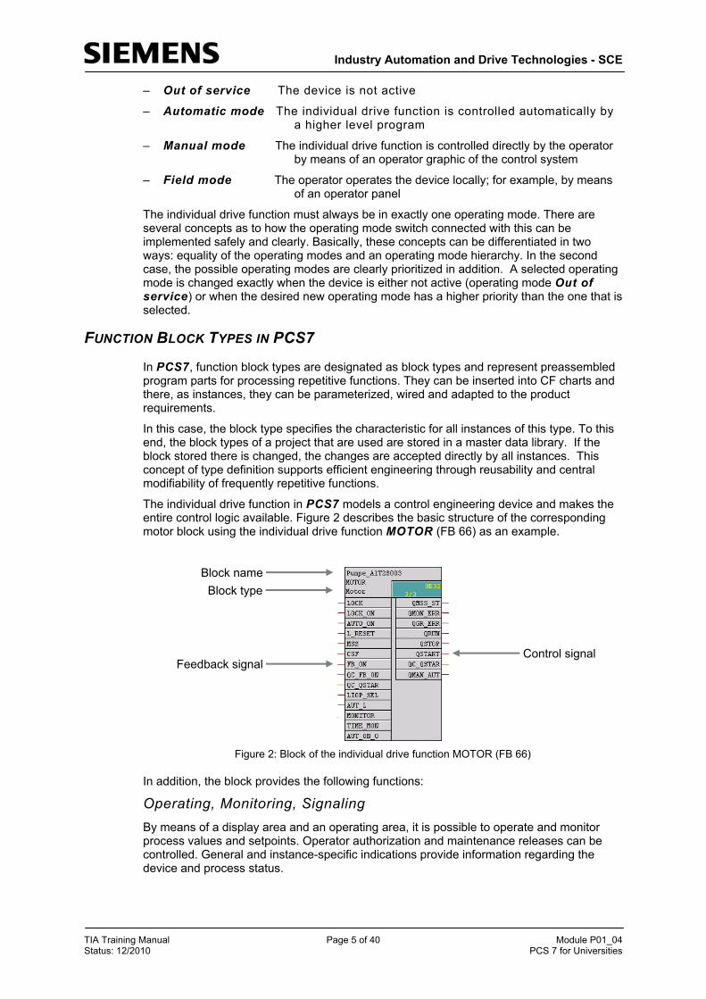
– Out of service The device is not active
– Automatic mode The individual drive function is controlled automatically by a higher level program
– Manual mode The individual drive function is controlled directly by the operator by means of an operator graphic of the control system
– Field mode The operator operates the device locally; for example, by means of an operator panel
The individual drive function must always be in exactly one operating mode. There are several concepts as to how the operating mode switch connected with this can be implemented safely and clearly. Basically, these concepts can be differentiated in two ways: equality of the operating modes and an operating mode hierarchy. In the second case, the possible operating modes are clearly prioritized in addition. A selected operating mode is changed exactly when the device is either not active (operating mode Out of service) or when the desired new operating mode has a higher priority than the one that is selected.
FUNCTION BLOCK TYPES IN PCS7
In PCS7, function block types are designated as block types and represent preassembled program parts for processing repetitive functions. They can be inserted into CF charts and there, as instances, they can be parameterized, wired and adapted to the product requirements.
In this case, the block type specifies the characteristic for all instances of this type. To this end, the block types of a project that are used are stored in a master data library. If the block stored there is changed, the changes are accepted directly by all instances. This concept of type definition supports efficient engineering through reusability and central modifiability of frequently repetitive functions.
The individual drive function in PCS7 models a control engineering device and makes the entire control logic available. Figure 2 describes the basic structure of the corresponding motor block using the individual drive function MOTOR (FB 66) as an example.
Figure 2: Block of the individual drive function MOTOR (FB 66)
In addition, the block provides the following functions:
Operating, Monitoring, Signaling By means of a display area and an operating area, it is possible to operate and monitor process values and setpoints. Operator authorization and maintenance releases can be controlled. General and instance-specific indications provide information regarding the device and process status.
Block name
Block type
Feedback signal Control signal

Industry Automation and Drive Technologies - SCE
TIA Training Manual Page 6 of 40 Module P01_04 Status: 12/2010 PCS 7 for Universities
Controlling the Signals Control signals can be read out either statically or pulsed. The signal status -i.e., the quality of the control signals- is monitored. Internal and external setpoints as well as simulated values can be specified. In addition, ramps or dead zones can be set.
Monitoring The block is able to monitor limits and if the limits are violated, generate corresponding warnings or alarms. In addition, feedback of control signals can be monitored.
Lock Functions The block allows for the following: simple start enable, lock without reset as well as lock with reset. It implements a motor protection function that can switch the motor off if there is a thermal overload. In addition, a fast stop is provided for motors that have the highest priority in all operating modes and operating states. If there is an lock, the device is automatically taken to a de-energized state, and thus taken to a defined safe state.
Operating Mode Selection The operating modes introduced above: Local mode, automatic mode, manual mode and out of service mode are available to the PCS7 for all individual drive functions. They are prioritized descending, in the sequence listed; automatic and manual mode have the same priority. In addition, it is possible to take the block into another operating mode by means of configurable input parameters, regardless of the currently available control (forcing operating modes).
Picture Blocks with Different Views For each block type, picture blocks provide the corresponding block symbol, and depending on the application case, corresponding views. Typical picture blocks are, for example, the block symbol itself, the parameter view of motors and valves, or the limit view of motors.
This listing clearly indicates the complexity and the functional scope of a customary individual drive function. The number of available input and outputs for these block types is correspondingly large. For example, the individual drive function MOTOR (FB 66) has a total of 53 connections. To keep the complexity of the program draft low nevertheless, we can hide inputs or outputs that are not needed. In addition, the individual drive functions in PCS7 use a uniform and system-wide scheme to designate the inputs and outputs.
The individual drive functions in PCS7 offer a large functional scope and guarantee constant high quality and reliability of the algorithms used. All block types have been tested extensively and have proven themselves industrially. This considerably shortens the effort for developing high performance, qualitatively high grade solutions.
LITERATURE
[1] Seitz, M. (2008): PLCs. Hanser Fachbuchverlag (Publisher of Technical Literature)
[2] SIEMENS (2009): Process Control System PCS 7: PCS 7 Standard Library V71.
[3] SIEMENS (2009): Process Control System PCS 7: PCS 7 Advanced Process Library V71.

Industry Automation and Drive Technologies - SCE
TIA Training Manual Page 7 of 40 Module P01_04 Status: 12/2010 PCS 7 for Universities
STEP BY STEP INSTRUCTIONS
TASK
As the first program in the Continuous Function Chart (CFC), we are creating a pump motor for discharging the liquid from reactor R001. The pump motor has an output to control the pump, and a feedback to check whether the pump is actually running.
Table 3: Assignment List
Symbol Address Data Type Symbol Comment A1.T2.A1T2S003.SO+.O+ I 6.1 BOOL Pump outlet reactor R001
feedback running A1.T2.A1T2S003.SV.C Q 6.3 BOOL Pump outlet reactor R001
control signal
Figure 3: Part of P&ID
When the program is created, a preassembled chart 'MOTOR’ from a PCS7 library is used. This chart is copied to the project’s own master data library and adapted there. Then, the program is loaded into the PLC simulation, and tested.
Reactor

Industry Automation and Drive Technologies - SCE
TIA Training Manual Page 8 of 40 Module P01_04 Status: 12/2010 PCS 7 for Universities
OBJECTIVE
In this chapter, the student will learn the following:
– Symbol table; setting up and importing symbols
– Using master data libraries and process tag types
– Setting up and editing CFCs
– Compiling a project centrally and downloading it
– Testing the program using the control functions in the CFC
PROGRAMMING
1. Before we start programming the individual drive functions for the pump motor, the symbols for the global variables are set up. To do this, we select the component view in the SIMATIC Manager, highlight the folder ’S7 Program(1)’ and open the symbol table by double clicking on Symbol.
( SIMATIC Manager View Component view S7 Program(1) Symbols)

Industry Automation and Drive Technologies - SCE
TIA Training Manual Page 9 of 40 Module P01_04 Status: 12/2010 PCS 7 for Universities
2. In the symbol table, we now specify the symbol and symbol comment for each operand.
3. If available, we can also import the content for the complete symbol table in the *.dif format. ( Symbol Table Import). In this case, the imported table is integrated in the existing table.
Industry Automation and Drive Technologies - SCE
TIA Training Manual Page 10 of 40 Module P01_04 Status: 12/2010 PCS 7 for Universities
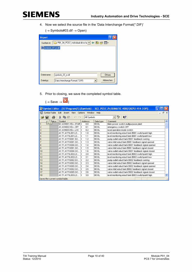
4. Now we select the source file in the ’Data Interchange Format(*.DIF)’
( Symbols#03.dif Open)
5. Prior to closing, we save the completed symbol table.
( Save )

Industry Automation and Drive Technologies - SCE
TIA Training Manual Page 11 of 40 Module P01_04 Status: 12/2010 PCS 7 for Universities
6. In extensive libraries, PCS7 makes a large number of completed blocks and also preassembled charts -socalled templates- available. We want to use just such a template. To this end, we open the PCS7 Library V71.
( File Open Libraries PCS7 Library V71 OK)

Industry Automation and Drive Technologies - SCE
TIA Training Manual Page 12 of 40 Module P01_04 Status: 12/2010 PCS 7 for Universities
7. To drag this template from the library into our project, we place the project next to the library window.
( Window Arrange Vertically)

Industry Automation and Drive Technologies - SCE
TIA Training Manual Page 13 of 40 Module P01_04 Status: 12/2010 PCS 7 for Universities
8. In the component view of our multi-project, we highlight -in the master data library ’SCE_PCS7_Lib’- the folder ’Charts’. With the mouse, we drag the template ’MOTOR’ from the folder ’Templates’ of the PCS7 Library V71 to the folder ’Charts’. Then we close the PCS7 Library V71.
( SCE_PCS7_Lib Charts PCS7 Library V71 Templates MOTOR )
Note: Since we are using this template several times for controlling the motor, it is first copied to the master data library ’SCE_PCS7_Lib’ in our multi-project.
This master data library ensures that within a project, always the same version of blocks and chart templates (process tag types) is used.
!

Industry Automation and Drive Technologies - SCE
TIA Training Manual Page 14 of 40 Module P01_04 Status: 12/2010 PCS 7 for Universities
9. For the next steps, we return to the plant view.
( View Plant View)
10. In the master data library, we now cut the entire folder ’MOTORS’ from the templates.
( SCE_PCS7_Lib Templates MOTORS Cut)

Industry Automation and Drive Technologies - SCE
TIA Training Manual Page 15 of 40 Module P01_04 Status: 12/2010 PCS 7 for Universities
11. The folder we copied is pasted again under Process tag types.
( Process tag types Paste)
Note: Using process tags types as templates for measuring points allows us to later make changes centrally. When the process tag types are changed, the measuring points in the project are adjustedautomatically.
!
Industry Automation and Drive Technologies - SCE
TIA Training Manual Page 16 of 40 Module P01_04 Status: 12/2010 PCS 7 for Universities
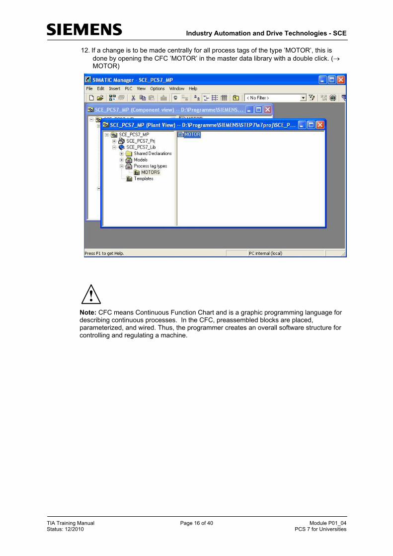
12. If a change is to be made centrally for all process tags of the type ’MOTOR’, this is done by opening the CFC ’MOTOR’ in the master data library with a double click. ( MOTOR)
Note: CFC means Continuous Function Chart and is a graphic programming language for describing continuous processes. In the CFC, preassembled blocks are placed, parameterized, and wired. Thus, the programmer creates an overall software structure for controlling and regulating a machine.
!

Industry Automation and Drive Technologies - SCE
TIA Training Manual Page 17 of 40 Module P01_04 Status: 12/2010 PCS 7 for Universities
13. A CFC consists of sub-charts with six partitions respectively. In the overview, all 6 partitions with their gray margin bars are displayed. On the margin bars, to the left the coming signals are shown, and to the right the going signals of a partition. Double clicking on a partition takes us to the partition view.
( Overview Double click on the first partition)
Note: Using the registers on the lower bar you can switch between sub-charts (maximum A to Z). Here, however, initially only sub-chart A exists.
!

Industry Automation and Drive Technologies - SCE
TIA Training Manual Page 18 of 40 Module P01_04 Status: 12/2010 PCS 7 for Universities
14. In our process tag type ’MOTOR’ we want to make a change at the block ’MOTOR’. To this end, we open its properties with a double click.( MOTOR)
15. Since we don’t want to change the general properties such as controlling and
monitoring capability, we switch to the connections. ( Connections)

Industry Automation and Drive Technologies - SCE
TIA Training Manual Page 19 of 40 Module P01_04 Status: 12/2010 PCS 7 for Universities
16. The connections are shown in a table, together with numerous settable properties. The most important properties will be presented below. In our process tag type 'MOTOR’ we only want to delete the invisibility for ’AUT_ON_OP’. Thus, this connection is
shown in the partition. ( AUT_ON_OP OK)
Note: With a mouse click on the heading of a property, the items in this column are sorted alphabetically <<?>>.
!

Industry Automation and Drive Technologies - SCE
TIA Training Manual Page 20 of 40 Module P01_04 Status: 12/2010 PCS 7 for Universities
17. The block ’MOTOR’ has become larger in the partition, of course, and overlaps with the comment field. We are solving this problem by moving either the block or the comment field, and the block is shown again completely. ( MOTOR)
18. We now simply close the process tag type. Changes are saved automatically. ( )

Industry Automation and Drive Technologies - SCE
TIA Training Manual Page 21 of 40 Module P01_04 Status: 12/2010 PCS 7 for Universities
19. To use the process tag type ’MOTOR’, we move it directly to the chart folder ’A1T2S003’. ( MOTOR A1T2S003)
20. The chart is now named like the chart folder and opened with a double click.
( A1T2S003 A1T2S003)

Industry Automation and Drive Technologies - SCE
TIA Training Manual Page 22 of 40 Module P01_04 Status: 12/2010 PCS 7 for Universities
21. A double click opens the properties of the block ’MOTOR’.
( MOTOR)
22. Under Properties/General, we change the name of the block.
( pump_A1T2S003 OK)

Industry Automation and Drive Technologies - SCE
TIA Training Manual Page 23 of 40 Module P01_04 Status: 12/2010 PCS 7 for Universities
23. Now, we change the time for feedback monitoring of the motor block to 10.0 seconds. To this end, we open the property dialog for the input ’TIME_MON’ with a double click. ( TIME_MON 10.0 OK)
24. Next, we wire the feedback to the input operand. This is done by right clicking on the input ’VALUE’ at the CH_DI block. Then, we select the wiring to the operand.
( VALUE Interconnection to Address)

Industry Automation and Drive Technologies - SCE
TIA Training Manual Page 24 of 40 Module P01_04 Status: 12/2010 PCS 7 for Universities
Note: Like the CH-DO, the CH-DI block is a driver block for interfacing the PLC’s IO. If at one of these blocks the VALUE is wired to an operand that is also configured in the hardware configuration, the input MODE is later supplied automatically with data during the compilation run.
For this to happen, we have to select ’Generate module driver’ during the compilation run.
25. We can then conveniently select the operand directly from the symbol table. ( A1.T2.A1T2S003.S0+.0+)
!

Industry Automation and Drive Technologies - SCE
TIA Training Manual Page 25 of 40 Module P01_04 Status: 12/2010 PCS 7 for Universities
26. We now wire the control of the output operand. This is done by right-clicking on the input ’VALUE’ at the CH_DO block. We then select Interconnection to Address.
( VALUE Interconnection to Address)
27. Again we can conveniently select the operand directly from the symbol table. ( A1.T2.A1T2S003.SV.C)

Industry Automation and Drive Technologies - SCE
TIA Training Manual Page 26 of 40 Module P01_04 Status: 12/2010 PCS 7 for Universities
28. But before we compile and download the program for the pump motor, we have to start
the PLC simulation S7 PLCSIM. ( )
29. The PLC simulation behaves like an actual SIMATIC S7 CPU. However, the inputs and outputs have to be inserted first before they can be monitored and operated. ( Insert Input Variable Insert Output Variable)

Industry Automation and Drive Technologies - SCE
TIA Training Manual Page 27 of 40 Module P01_04 Status: 12/2010 PCS 7 for Universities
30. Now we have to enter the correct byte addresses. EB6 AB6)
31. To download from the SIMATIC Manager into the S7 PLCSIM via the correct interface, we are correctly setting the PG/PC interface.
( SIMATIC Manager Options Set PG/PC Interface)

Industry Automation and Drive Technologies - SCE
TIA Training Manual Page 28 of 40 Module P01_04 Status: 12/2010 PCS 7 for Universities
32. As interface, we are setting here PLCSIM(TCP/IP). ( PLCSIM(TCP/IP) OK)
33. In the plant view, we can now highlight the project folder and start compiling and downloading the objects.
( Plant View SCE_PCS7_Prj PLC Compile and Download Objects)

Industry Automation and Drive Technologies - SCE
TIA Training Manual Page 29 of 40 Module P01_04 Status: 12/2010 PCS 7 for Universities
34. In the following selection, ’Compile and Download’ is selected for the hardware and the
charts. Then the folder ’Charts’ is highlighted and its settings are checked. (
Charts Edit)
35. When compiling the charts, it is important to compile the entire program and have the module drivers generated.
( Entire program Generate module drivers S7 Download)
Industry Automation and Drive Technologies - SCE
TIA Training Manual Page 30 of 40 Module P01_04 Status: 12/2010 PCS 7 for Universities
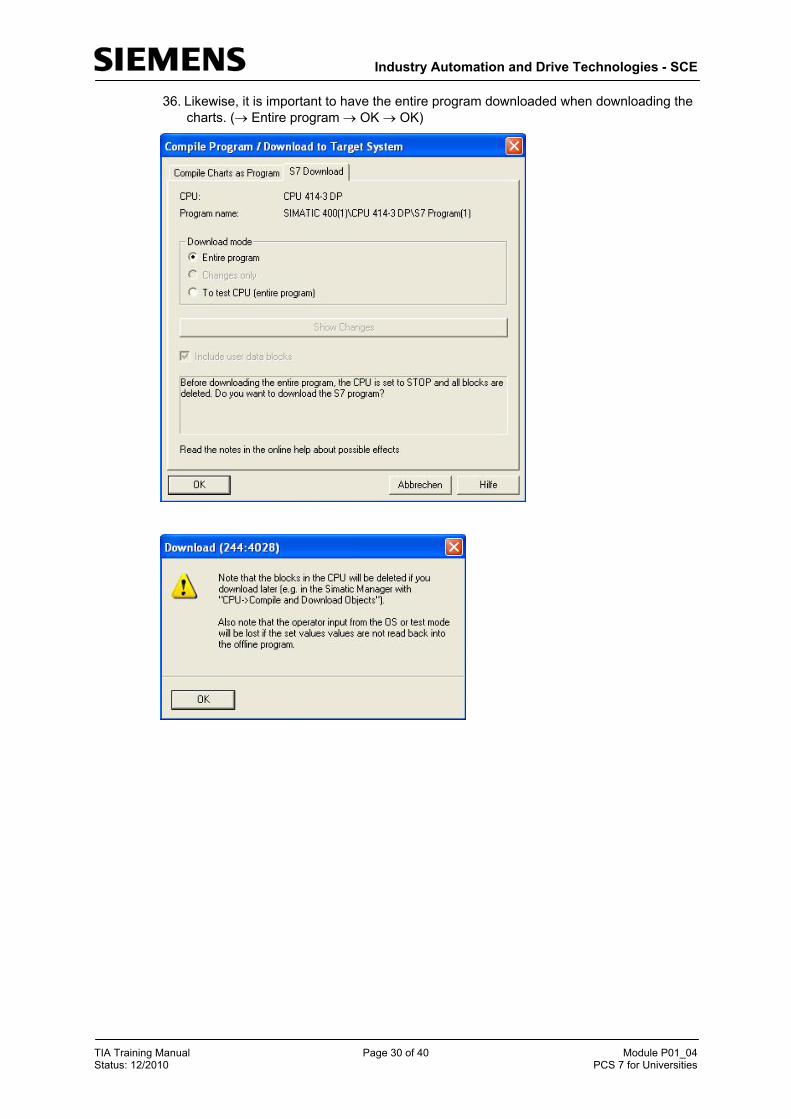
36. Likewise, it is important to have the entire program downloaded when downloading the charts. ( Entire program OK OK)

Industry Automation and Drive Technologies - SCE
TIA Training Manual Page 31 of 40 Module P01_04 Status: 12/2010 PCS 7 for Universities
37. Now, we can start ’Compile and Download’. The warnings and notes about plant safety should be read carefully. Prior to ’Compile and Download’ the CPU has to be switched to the ’STOP’ mode. ( Start OK Yes)
Industry Automation and Drive Technologies - SCE
TIA Training Manual Page 32 of 40 Module P01_04 Status: 12/2010 PCS 7 for Universities
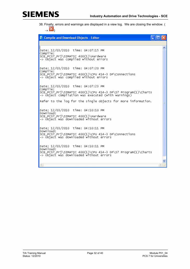
38. Finally, errors and warnings are displayed in a view log. We are closing the window. (
)

Industry Automation and Drive Technologies - SCE
TIA Training Manual Page 33 of 40 Module P01_04 Status: 12/2010 PCS 7 for Universities
39. If you want to view details of the view log, click on ’Single Object’. ( Single Object Close Close)
Note: Here, only the warning is displayed that the system cleared the empty OB1.
40. To test the program, the CPU in S7 PLCSIM is switched to ’RUN-P’. ( S7-PLCSIM RUN-P)
!

Industry Automation and Drive Technologies - SCE
TIA Training Manual Page 34 of 40 Module P01_04 Status: 12/2010 PCS 7 for Universities
41. Before we can monitor the individual blocks in the CFC, the chart has to be switched to
the test mode first. ( CFC )
42. We still can’t do any monitoring unless the individual blocks are explicitly set for monitoring.
( Pump_A1T2S003 Watch On)

Industry Automation and Drive Technologies - SCE
TIA Training Manual Page 35 of 40 Module P01_04 Status: 12/2010 PCS 7 for Universities
43. To switch on the pump motor from the CFC, we first have to set a few inputs. These are, in the following sequence:
To activate the wiring and passivating the operation in WinCC LIOP_SEL == 1
Wiring for manual/automatic mode to automatic AUT_L == 1
Switching to automatic mode AUTO_ON == 1
( LIOP_SEL 1 OK AUT_L 1 OK AUTO_ON 1 OK)

Industry Automation and Drive Technologies - SCE
TIA Training Manual Page 36 of 40 Module P01_04 Status: 12/2010 PCS 7 for Universities
44. We can now watch the process as well as the reaction of the plant in the CFC and in the S7 PLCSIM.
Note: For testing, it should not be omitted to set the feedback I 6.1 within 10 seconds after activating the output Q 6.3 in S7 PLCSIM. If this is not done, the block switches off Pump_A1T2S003 and reads out an error.
!
Note: If there is no feedback, the pump block not only switches the actuator signal QSTART to 0, but by setting the output QMON_ERR to 1 also indicates that the running indication of the pump did not arrive in time. To prevent damage through repeated attempts to switch it on, the pump block has to be reset first before making another attempt.
To this end, we have to set the input L_RESET briefly to 1 and then to 0 again!
By double clicking on this input parameter of pump block Pump_A1T2S003 the following dialog is displayed. In the field Value, we first enter a 1, then transfer this value to the control system by clicking on ’Apply’ and set the error outputs to 0. To return to the normal method of functioning, L_RESET is reset to the original state by entering 0 and once more clicking on ’Apply’.
!

Industry Automation and Drive Technologies - SCE
TIA Training Manual Page 37 of 40 Module P01_04 Status: 12/2010 PCS 7 for Universities
!
Note: If AUTO_ON is still set to 1 when resetting L_RESET, the block immediately sets the QSTART signal again – and if there is no run feedback, switches it off again!
TESTING THE AUTOMATION LOGIC WITH THE SIMULATION
The manual input of process states to the simulated control system is possible with justifiable effort for testing smaller functions. In the case of more involved sequences with several dynamic process variables, the limits of what is feasible are quickly reached. Here, using a process simulation is advisable.
For that reason, the essential relationships of the process that we are automating here were mapped with the simulation software SIMIT for this course. The model maps the following: the dynamic behavior of the pumps, valves, containers, reactors as well as the local operator panel with main switch, emergency off, switchover to local field operation and the corresponding control elements. In comparison to reality, the dynamic processes are accelerated by a factor of 5 to 50 in order to keep waiting time short.
The interface of the simulator is shown in Figure 4. On the left, it shows the process scheme as well as the signal levels of the controller output and the measured quantity. To the right on top, the ochre-colored field operator control panel is shown, below it a number of control elements for the simulation.
Figure 4: Graphical User Interface of the Process Simulation
Industry Automation and Drive Technologies - SCE
TIA Training Manual Page 38 of 40 Module P01_04 Status: 12/2010 PCS 7 for Universities
Using the simulator is really simple – we only have to make sure that the program is started after S7 PLCSIM and the assignment of the inputs and outputs was not changed.
With the simulator, it is very easy to check the pump control:
1. After S7 PLCSIM the simulation program is started.
2. Simulation starts with 75% filled educt tanks, all others are empty. With the option ’RESET’, this state can be restored any time in the simulation control system. The option ’RESET 50%’ fills all tanks -as shown in Figure 4- to 50%.
3. For testing, the motor block is set as described in the previous section under Step 43 – in the simulation, the control signal of the pump lights up green.
4. The simulated motor start takes about 2 seconds. Then, the running indicator for the motor lights up green in the simulation, and the signal level for binary input I 6.1 of the control system is set.
5. To open the conveying route, the valve for product tank T3.B001 has to be opened. This valve is operated in the exercise below by means of a suitable individual drive function. In the simulation -with the pump switched on and the valve open- we can watch how the content of reactor T2.R001 is pumped into product tank T3.B001.
6. By means of simulation controllers, the product tanks can be discharged and the educt tanks can be charged. When charging by means of the simulation controller, first we have to separate the simulation from the control system. To this end, we click the button with the horizontal line once. Then, we can open the valve with the button next to it on the right. The control signal lights up green and after approximately 1 second, the signal of the limit switch follows for the Open position. After another 5 to 10 seconds, the first changes in the level are visible.
7. With ’RESET’ and ’RESET 50%’, we can take the simulation to a defined state again.

Industry Automation and Drive Technologies - SCE
TIA Training Manual Page 39 of 40 Module P01_04 Status: 12/2010 PCS 7 for Universities
EXERCISES
We are going to apply what we learned in the theory chapters and the step by step instructions to the exercises. We are going to use the existing multi-project in the step by step instructions (PCS7_SCE_0104_R1009.zip) and expand it.
The objective of these exercises is to generate a CFC that controls the valves of the plant. We will build on the knowledge gained from the step by step instructions where a similar CFC for controlling a motor was created.
In addition, we are creating a CFC for standardizing the level; i.e., an analog input value.
TASKS
The following exercises are based on the step by step instructions. For each task, the corresponding steps in the instructions can be used as an aid.
1. Based on Table 2, decide which individual drive function is to be used for the present valve, and import the individual drive function into the project library. Also, the template for the valve is to be inserted at the process tag types in the master data library.
2. In chart folder A1T3X001, an object instance of the valve control that was just generated in the master data library is to be inserted. If necessary, adapt the names of the blocks in the object instance.
3. Use an object instance of your newly generated object type for controlling valve =SCE.A1.T3.V001 with which a connection between reactor =SCE.A1.T2.R001 and product container =SCE.A1.T3.B001 can be opened. The valve is to be controlled with the symbols listed in Table 4.
4. Now, test your implementation with the SIMIT model.
5. Add FC 275 (CH_AI) from the PCS7 Library V71 to your project.
6. Create a new CFC in chart folder A1T2L001. Drag the block CH_AI (FC 275: Analog Input) that was just added to the first partition of the CFC. Assign a name to the CFC and the block correspondingly. Connect the ‘VALUE’ input of the block to the symbol for the actual value level of the reactor in Table 4. Set the ‘VHRANGE’ of the block to -82.945 and the ‘VLRANGE’ to 2398.945 (these values are used to standardize the measured value).
To ensure that the MODE inputs of the CH-DI and CH-DO blocks are wired correctly, make sure that the option ‘Generate module driver’ is selected for compilation.
Table 4: Symbols for Implementing Valve Control
Symbol Address Data Type Symbol Comment
A1.T3.A1T3X001.XV.C Q 2.0 BOOL Valve inlet product tank B001 control signal
A1.T3.A1T3X001.GO+-.O+ I 12.3 BOOL Valve inlet product tank B001 feedback signal opened
A1.T3.A1T3X001.GO+-.O- I 12.5 BOOL Valve inlet product tank B001 feedback signal closed
A1.T2.A1T2L001.LISA+.M IW 512 WORD Current value level reactor R001

Industry Automation and Drive Technologies - SCE
TIA Training Manual Page 40 of 40 Module P01_04 Status: 12/2010 PCS 7 for Universities
Figure 5: Part of P&ID
Reactor
Product Tank