hera600 series user guide - eseye ltd · page 3 thank you for choosing an eseye dataflex hera600...
TRANSCRIPT

HERA600 Series
User Guide
Document Number: 8193
Revision 1.4
April 2014

Page 2
DATAFLEX COMMUNICATIONS
2014 Dataflex Design Communication Ltd
8 Frederick Sanger Road,
Surrey Business Park
Guilford • Surrey GU2 7YD • UK
Phone +44 1483 685 200
Page 3
Thank you for choosing an Eseye Dataflex HERA600 series router!
All Eseye Dataflex products are M2M-grade and can include use of the Anynet global
managed connectivity. There are so many different connected applications for which this
router can be used to include them all in this document. We regularly add user guides to the
suite of guides for the HERA600 series so if you need information that you do not find here
please feel free to ask us for it.
This guide has been written for use by technically competent persons with a good
understanding of communications technologies used for 3G and Wi-fi router products, and of
the requirements for their specific application
This document is a companion to the ‘getting started’ guide which came with your product
and describes in more detail the features of the product, specifically, it will provide you with
more information on how to configure your HERA600 device to work with your existing
network infrastructure.
Further documents relating to other aspects of the device such as security and QoS are
available.
Eseye Dataflex HERA600 products are available in a range of form factors, but all variants of
the product have high speed (3G or 4G) cellular connectivity at the core of their design.
Currently there are four models in the HERA600 range -
Model 600 3G (HSPA) router designed for M2M applications with 4 Ethernet ports + 2 serial ports.
Model 601 As model 600 but with HSPA+ capability
All models can be configured by command line (CLI), web interface (HTTP or HTTPS) or via an
approved management system such as SNMP or a TR-069 platform.
Important
The contents of this document are subject to revision without notice due to continued
progress in methodology, design, and manufacturing.
Make sure you are using the latest information by downloading the latest version of this
document from www.eseye.com
Page 4
TABLE OF CONTENTS
1 INTRODUCTION 6
1.1 In the Box 6
1.2 What you need to configure your HERA600 Series router 6
1.3 Configuration Strategy 6
2 INTERFACES 7
2.1 Wired Interfaces 7
2.2 Virtual Interfaces 7
2.3 Wireless Interfaces 7
2.4 Physical ports connections 7
2.4.1 Power Connector 8
2.4.2 3G connections 8
2.4.3 Serial connection 8
2.4.4 Data connections 8
2.4.5 Wi-Fi connection 8
2.5 Mobile Interfaces 9
2.6 Other Interfaces 9
2.6.1 Wired Ethernet Uplink 9
3 CONFIGURATION 10
3.1 Configuration via the Web Interface 10
4 BASIC CONFIGURATION 12
4.1 Change APN Settings 12
4.2 Testing SIM cards 12
4.2.1 Testing internal MFF AnyNet SIM – connecting to an external mobile network 12
4.2.2 Testing 2FF SIM cards - connecting to an external mobile network 14
4.3 Setting Basic DHCP parameters 15
4.4 Port Forwarding 15
5 ADVANCED CONFIGURATION 17
5.1 Setting the Local IP address 17
5.2 Setting 3G Network Parameters 18
5.2.1 WAN Configuration Changes. 19
5.2.2 Setting up the network provider selection 21
5.2.3 Setting Advanced DHCP parameters 22
5.2.4 DHCP SERVER SUBNET CONFIGURATION HELP 22
5.2.5 Create a new DHCP subnet 23
5.2.6 How to edit an existing DHCP subnet 23
5.2.7 Adding a new DHCP client option 24
5.2.8 Create a new DHCP host 25
5.2.9 DHCP server fixed IP/MAC mapping help 26
5.2.10 Changing and adding Users Login Details 26
5.2.11 Advanced Log-in settings 27
6 Adding a default route 28
6.1 Checking the configuration 28
6.2 Name server resolution (DNS) 29
7 CLI Basic configuration 30
7.1 Changing the default LAN address 30
7.2 Setting an WAN username and Password, or IP address 30
7.3 Adding a default route 31
7.3.1 Adding and altering DHCP server subnets 31
7.4 Changing the default username and password of the Web Admin and CLI access 31
Page 5
8 FURTHER ADVANCED CONFIGURATION 32
8.1 CLI Advanced Firewall configuration 32
8.1.1 Changing the Firewall – reserved mapping via CLI 32
8.2 Simple Network Management Protocol 32
9 PROVISIONING 33
10 FIRMWARE UPDATING 34
11 HEALTH MONITORING AND DUAL SIM MANAGEMENT 35
11.1 Health Monitoring Feature 35
11.2 Failover Actions 35
11.3 Web page configuration 36
11.3.1 Web Page Configuration Steps 36
12 ESEYE AND DATAFLEX TECHNICAL SUPPORT 38

Page 6
1 INTRODUCTION
The HERA600 Series is a 2G and 3G enabled Wi-fi router with optional embedded ESEYE
AnyNet SIM to provide continuation of service and ensure connectivity worldwide.
Tough and durable the HERA600 series comes encased in rugged aluminium and is suitable
for direct mounting and secure installations.
The router is encryption capable and adheres to Eseye’s strictest quality assurance which
means you don’t have to worry about data security, connection reliability or continuation of
service as your connecting equipment can be monitored, accessed and reconfigured
without physically mobilising staff and resources to sites.
1.1 In the Box
The standard HERA600 series product includes the following items.
1 HERA600 or HERA601 Router
2 Mains adapter (UK/EU depending on location)
3 RJ45 Ethernet cable
4 GSM antenna
5 Wifi Antenna (Wifi units only)
6 SIM slot cover (optional)
7 Quick Start User Guide
This can be modified upon customer request.
1.2 What you need to configure your HERA600 Series router
All HERA600 series routers will ship preconfigured unless otherwise stated by our customers.
However should you wish to make changes please make sure you have the following
available:
1 Username and password details for the router
2 Eseye or other Mobile Network provider APN details
3 SIM number(s) (starting with 8944XXXXXXXX…)
4 Your LAN network details
5 Your IP Address (if working remote from the device)
1.3 Configuration Strategy
In short you should look to following the instructions from the quick start user guide as
supplied with the unit.
LAN/WAN configuration
APN configuration
Port forwarding
Page 7
2 INTERFACES
2.1 Wired Interfaces The HERA600 products have four 10 / 100 Mb/s Ethernet connectors which can be used to
connect to devices such as computers, video cameras and telemetry sensors. Each port is
autosensing so that it does not matter if you use a straight or crossover cable.
These ports can be enabled to act as a straightforward Ethernet hub where all the ports are
effectively tied together internally or as an advanced VLAN switching where each port may
also be allocated a specific function such as a De-Militarised Zone (DMZ) uplink to an
external WAN interface (e.g. DSL, satellite, Fiber, etc.)
Some HERA600 products also support serial connections for connection to industrial
equipment and legacy device. Full hardware flow control is available provided the correct
cables are used.
2.2 Virtual Interfaces All HERA600 products also support ‘virtual interfaces’ allowing WAN services to be terminated
internally without the need for external modems.
2.3 Wireless Interfaces Optionally, HERA600 products can be specified with a Wireless LAN (WLAN) capability to
allow computers and telemetry devices to be wirelessly connected.
All products that have WLAN capability support WDA (Wireless Domain Access) to link co-
located Wireless networks together and WPS to allow devices to easily join the wireless
network.
The wireless capability depends on the product range
HERA600 Series IEEE 802.11 b/g 2.4 GHz
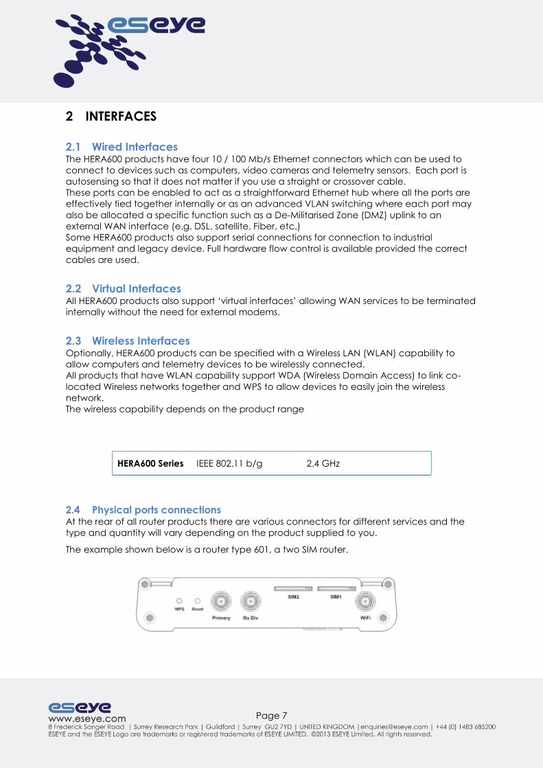
2.4 Physical ports connections At the rear of all router products there are various connectors for different services and the
type and quantity will vary depending on the product supplied to you.
The example shown below is a router type 601, a two SIM router.

Page 8
2.4.1 Power Connector
Important: Only use the mains power adapter supplied and connect a suitable (country
specific) mains lead to the IEC320 socket on the adapter.
2.4.2 3G connections
There are 3 possible SIM slots on the HERA600:
1. Internal MFF AnyNet SIM
2. SIM Slot 1
3. SIM Slot 2
2.4.3 Serial connection
On all router products there is an RJ45 socket (V.28) used for service and diagnostics. The
connector is specific to this product and can be obtained from your supplier
(recommended)
2.4.4 Data connections
The RJ45 LAN ports are 10/100Mbps auto-sense with the characteristics of a router/hub.
The USB port is either not available or not currently active on this device, but other products
have Wi-Fi and or 3G connectivity.
2.4.5 Wi-Fi connection
IAD supports a full Data Wireless Interface that supports 802.11.b/g/i specifications. It is also
possible to use WDA (Wireless Domain Access) to link co-located Wireless networks together.
Specification: IEEE 802.11b and IEEE 802.11g
Frequency: 2.4GHz - 2.5GHz
To be able to connect the computers, make sure that a wireless client adapter (WLAN client)
is installed on each computer.
Page 9
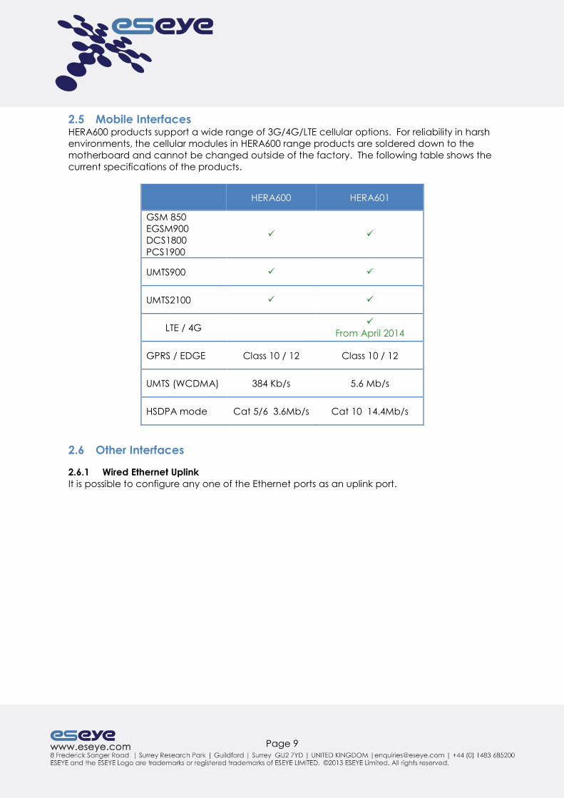
2.5 Mobile Interfaces HERA600 products support a wide range of 3G/4G/LTE cellular options. For reliability in harsh
environments, the cellular modules in HERA600 range products are soldered down to the
motherboard and cannot be changed outside of the factory. The following table shows the
current specifications of the products.
HERA600 HERA601
GSM 850
EGSM900
DCS1800
PCS1900
UMTS900
UMTS2100
LTE / 4G
From April 2014
GPRS / EDGE Class 10 / 12 Class 10 / 12
UMTS (WCDMA) 384 Kb/s 5.6 Mb/s
HSDPA mode Cat 5/6 3.6Mb/s Cat 10 14.4Mb/s
2.6 Other Interfaces
2.6.1 Wired Ethernet Uplink
It is possible to configure any one of the Ethernet ports as an uplink port.

Page 10
3 CONFIGURATION
Unless you ordered a pre-configured unit, you will need to make some simple configuration
changes in order to get your HERA600 device online for the first time.
When you have successfully done this once, it is possible to clone the configuration for
additional devices.
3.1 Configuration via the Web Interface To configure the HERA600 device for the first time, you must connect via telnet, SSH or via its
web based interface using a standard web browser such as Internet Explorer, Firefox,
Chrome, etc.
You also need to make sure that (initially at least) your PC and the HERA600 are on the same
LAN subnet.
From the factory, the HERA600’s IP address is 192.168.0.1. This IP address may vary depending
on customer requirements and you would have been informed it is different.
The device has a DHCP server. Once turned on, a simple way to connect to the HERA600 is
to disconnect your PC from your LAN, directly connect the HERA600 to your PC with an
Ethernet cable and either reboot your PC or renew its DHCP lease from the command line
using the windows ipconfig utility or alternatively using the Windows network repair
functionality.
When you are ready, type http://192.168.0.1 into the address bar of your browser and the
following login screen should appear -
Enter the default username ‘admin’ and password ‘admin’ then click OK. You will then see
the main configuration screen which looks like this –

Page 11
The status page gives you links to some of the configuration that are shown on the page –
alternatively you can select the “configuration” option to the left to give further
configuration options.
The screen you see above contains information currently configured on your HERA600 device
and contains links to configuration information about, for example, your connection details
and status to a cellular provider and gives information of devices connected to its Ethernet
ports, which allows access to the internet or your internal intranet services.
All HERA600 series routers will ship preconfigured unless otherwise stated by our customers.

Page 12
4 BASIC CONFIGURATION
4.1 Change APN Settings
Click MOBILE from the main menu and enter the details for the APN as provided by the
network operator. If you are using AnyNet SIM connectivity this would have been pre-
configured and you do not need to make any changes.
4.2 Testing SIM cards
This step can be done at any point in your configuration process however it is worth noting
that you may wish to set up security configuration before proceeding with SIM testing.
4.2.1 Testing internal MFF AnyNet SIM – connecting to an external mobile network
The internal SIM, if active, is always SIM1.
1. Power the HERA router on
2. Wait for the unit to finish booting and load the GUI webpage
3. Go to SUMMARY
Page 13
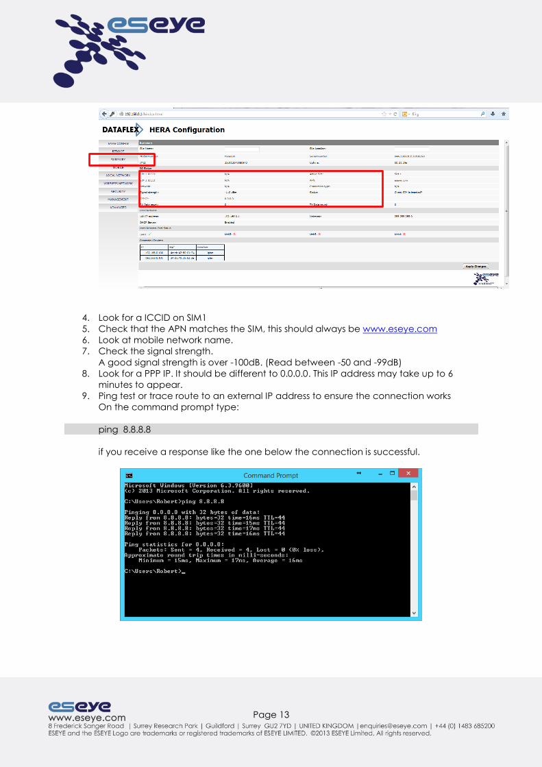
4. Look for a ICCID on SIM1
5. Check that the APN matches the SIM, this should always be www.eseye.com
6. Look at mobile network name.
7. Check the signal strength.
A good signal strength is over -100dB. (Read between -50 and -99dB)
8. Look for a PPP IP. It should be different to 0.0.0.0. This IP address may take up to 6
minutes to appear.
9. Ping test or trace route to an external IP address to ensure the connection works
On the command prompt type:
ping 8.8.8.8
if you receive a response like the one below the connection is successful.

Page 14
4.2.2 Testing 2FF SIM cards - connecting to an external mobile network
If there is an internal SIM in the HERA router, the external SIM will always be SIM 2.
1. Insert the SIM into an available slot
2. Power the HERA router on
3. Wait for the unit to finish booting and load the GUI webpage
4. Go to SUMMARY
5.
6. Look for a ICCID on the appropriate SIM slot
7. Check that the APN matches the type of SIM inserted, for instance www.eseye.com
8. Look to see what the network name is
9. Check the signal strength. A good signal strength is over -100dB. (Read between -50
and -99dB)
10. Look for a PPP IP. It should be different to 0.0.0.0. This IP address may take up to 6
minutes to appear.
10. Ping test or trace route to an external IP address to ensure the connection works
On the command prompt type:
ping 8.8.8.8
if you receive a response like the one below the connection is successful.

Page 15
4.3 Setting Basic DHCP parameters The device will come preconfigured with DHCP enabled unless otherwise specified by our
customers.
To change settings
1 Click on LOCAL NETWORK
2 Enter start and end addresses to specify the range
3 Click Apply changes (this button does not appear until changes have been made)
4.4 Port Forwarding
Some applications behind the device will have to use ‘port mapping’ techniques to keep a
particular port open which may be a requirement for some applications being used on the
equipment on the device
Page 16
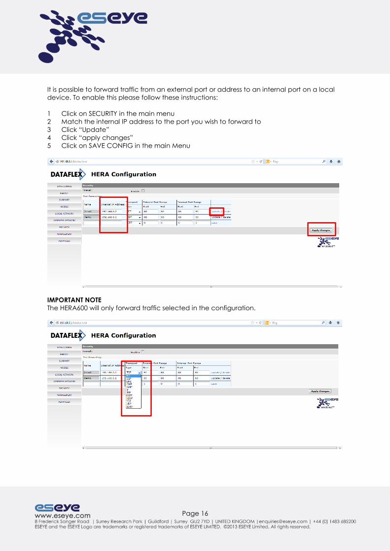
It is possible to forward traffic from an external port or address to an internal port on a local
device. To enable this please follow these instructions:
1 Click on SECURITY in the main menu
2 Match the internal IP address to the port you wish to forward to
3 Click “Update”
4 Click “apply changes”
5 Click on SAVE CONFIG in the main Menu
IMPORTANT NOTE
The HERA600 will only forward traffic selected in the configuration.

Page 17
5 ADVANCED CONFIGURATION
IMPORTANT NOTE
To ensure that configuration changes are applied and persist through a reboot please
ensure you click on the SAVE CONFIG in either Basic Configuration or Advanced
Configuration using the left handside Menu
5.1 Setting the Local IP address The default IP address of a HERA600 router as delivered from the factory is 192.168.0.1, you
may need to change this to suit your local network requirements.
To do this
1 select ADVANCED from the main menu
2 select “Configuration”
3 Select “LAN connections“
4 select ‘Change default LAN port IP address”.
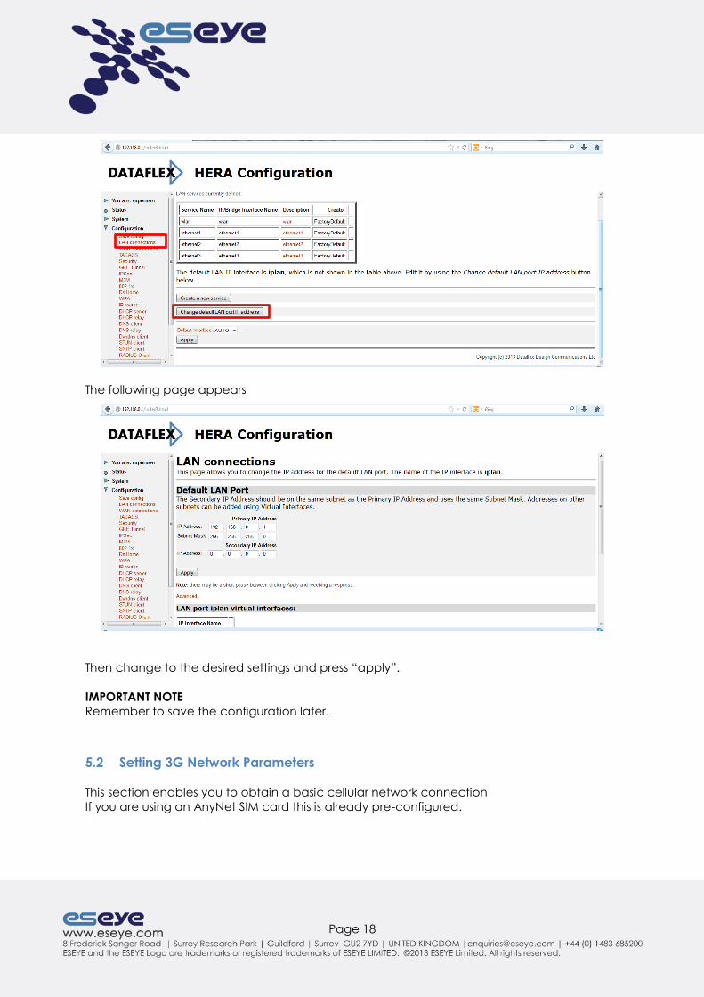
Page 18
The following page appears
Then change to the desired settings and press “apply”.
IMPORTANT NOTE
Remember to save the configuration later.
5.2 Setting 3G Network Parameters
This section enables you to obtain a basic cellular network connection
If you are using an AnyNet SIM card this is already pre-configured.

Page 19
Your network provider may supply you with network credentials supplied to you or you may
have to supply an IP address and subnet for the device to work over 3G and also select the
network that the 3G will poll for an address.
5.2.1 WAN Configuration Changes.
The following screen shots show were and what to configure on the device to activate the
connection.
1 Click on ADVANCED
2 Select WAN Connections
Then from the list of Services select “Edit” for the interface you wish to configure.
From the “Service” dropdown box select “PPP”

Page 20
Look for the “Dialin Auth:” setting – this can be PAP, CHAP or ‘none’ (your network provider
will give you the correct setting). These settings are pre-configured for routers using AnyNet
Connectivity.
Set the Username and Password (if required).
Once set, go to the bottom of the page and select “Apply”
IMPORTANT NOTE
Remember to save the configuration.
Page 21
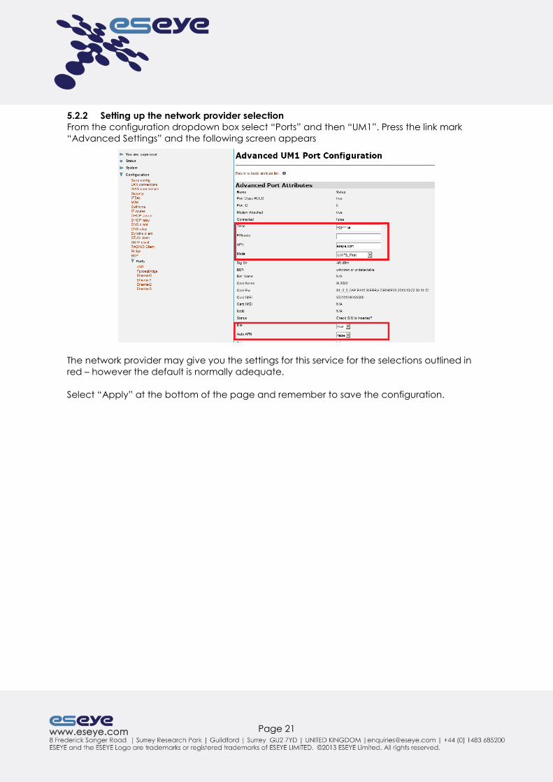
5.2.2 Setting up the network provider selection
From the configuration dropdown box select “Ports” and then “UM1”. Press the link mark
“Advanced Settings” and the following screen appears
The network provider may give you the settings for this service for the selections outlined in
red – however the default is normally adequate.
Select “Apply” at the bottom of the page and remember to save the configuration.

Page 22
5.2.3 Setting Advanced DHCP parameters
Using the ADVANCED Menu selecting Configuration you can pass on information
automatically to equipment that have received an address allocated by the device such as
DNS server details which will then be used by that device to configure that device’s DNS
server address list and also provide it with the default route out to the required network
5.2.4 DHCP SERVER SUBNET CONFIGURATION HELP
Subnet Value and Subnet Mask
These are the base values for your new DHCP server subnet. All addresses offered by the
DHCP server have to be located on a particular subnet. Also, if you wish to define some fixed
IP/MAC mappings, each fixed IP address must have a corresponding subnet. You do not
need to fill in this value if you use the Get subnet from IP interface option.
Use local host address as DNS server
If chosen, then the local IP address will be passed to DHCP clients who request a DNS server
address. For this facility to be useful, you should have the DNS relay configured to be active,
which can then forward DNS queries appropriately.
Use local host address as default gateway
If chosen, then the local IP address will be passed to DHCP clients who request a default
gateway address. Also, any manually configured value for the DHCP default gateway option
will be disregarded and overridden by this setting.
Get subnet from IP interface
If this option is activated (by choosing the name of an IP interface using the drop down list),
then your Subnet Value and Subnet Mask settings will be bound, and will keep track of, the
appropriate IP address and subnet mask. This is especially useful when combined with the
ability to use a default IP address range.
Page 23
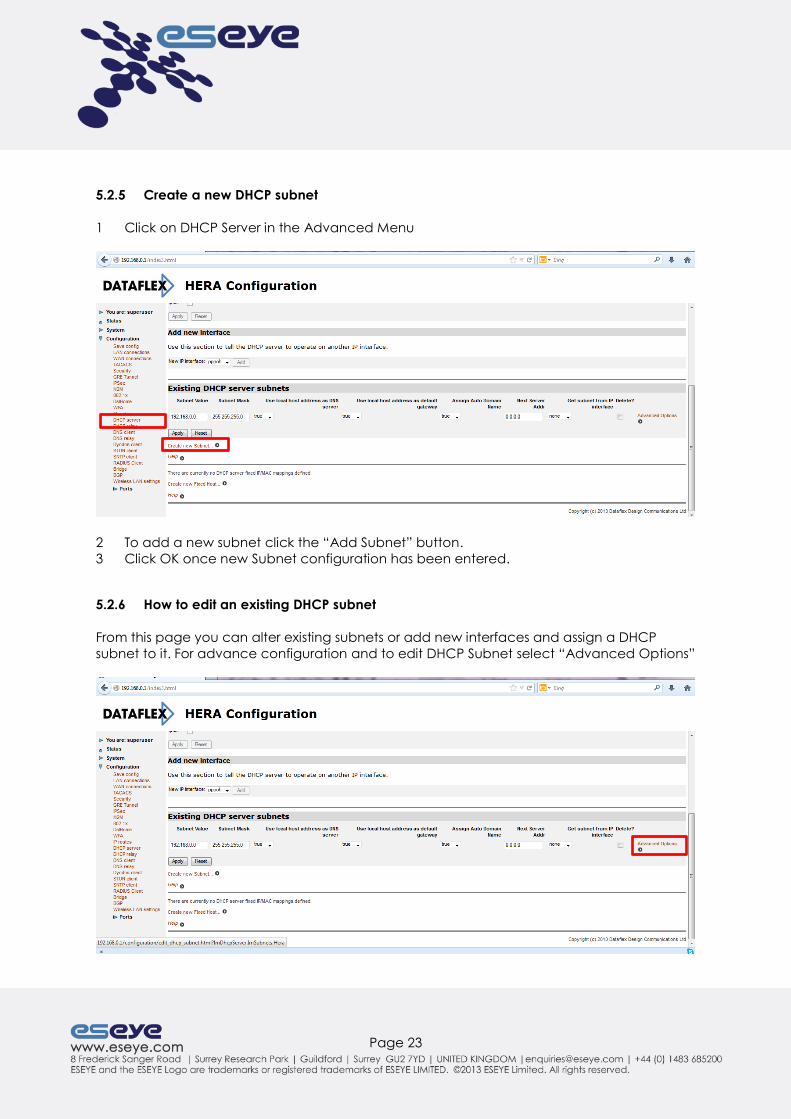
5.2.5 Create a new DHCP subnet
1 Click on DHCP Server in the Advanced Menu
2 To add a new subnet click the “Add Subnet” button.
3 Click OK once new Subnet configuration has been entered.
5.2.6 How to edit an existing DHCP subnet
From this page you can alter existing subnets or add new interfaces and assign a DHCP
subnet to it. For advance configuration and to edit DHCP Subnet select “Advanced Options”
Page 24
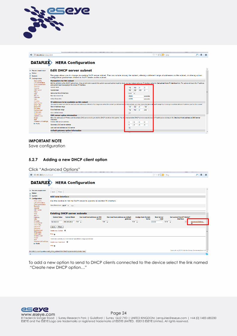
IMPORTANT NOTE
Save configuration
5.2.7 Adding a new DHCP client option
Click “Advanced Options”
To add a new option to send to DHCP clients connected to the device select the link named
“Create new DHCP option…”
Page 25
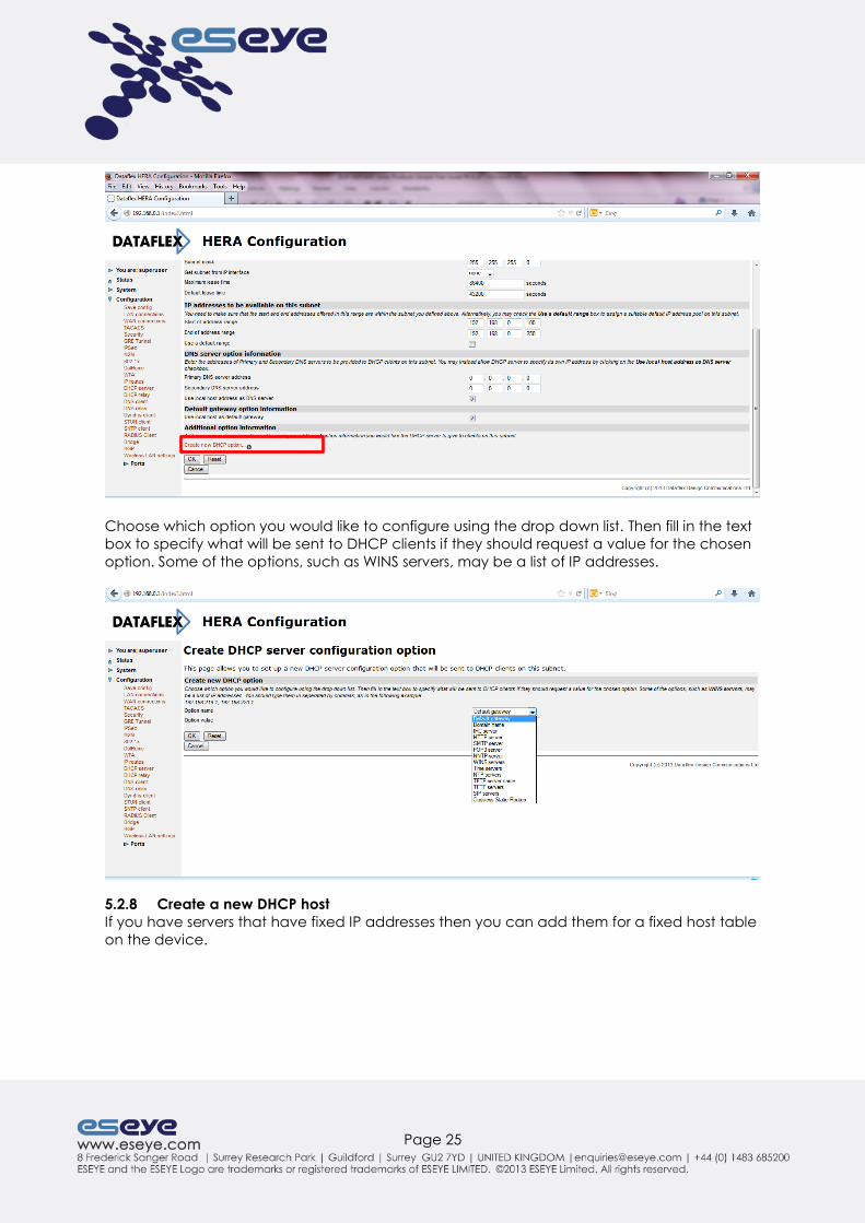
Choose which option you would like to configure using the drop down list. Then fill in the text
box to specify what will be sent to DHCP clients if they should request a value for the chosen
option. Some of the options, such as WINS servers, may be a list of IP addresses.
5.2.8 Create a new DHCP host
If you have servers that have fixed IP addresses then you can add them for a fixed host table
on the device.
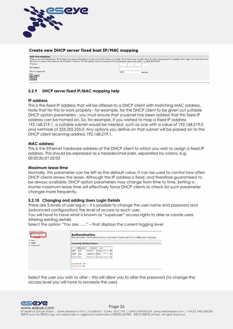
Page 26
5.2.9 DHCP server fixed IP/MAC mapping help
IP address
This is the fixed IP address that will be offered to a DHCP client with matching MAC address.
Note that for this to work properly - for example, for the DHCP client to be given out suitable
DHCP option parameters - you must ensure that a subnet has been added that this fixed IP
address can be homed on. So, for example, if you wished to map a fixed IP address
192.168.219.1, a suitable subnet would be needed, such as one with a value of 192.168.219.0
and netmask of 255.255.255.0. Any options you define on that subnet will be passed on to the
DHCP client receiving address 192.168.219.1.
MAC address
This is the Ethernet hardware address of the DHCP client to which you wish to assign a fixed IP
address. This should be expressed as 6 hexadecimal pairs, separated by colons, e.g.
00:20:2b:01:02:03
Maximum lease time
Normally, this parameter can be left as the default value. It can be used to control how often
DHCP clients renew the lease. Although the IP address is fixed, and therefore guaranteed to
be always available, DHCP option parameters may change from time to time. Setting a
shorter maximum lease time will effectively force DHCP clients to check for such parameter
changes more frequently.
5.2.10 Changing and adding Users Login Details
There are 3 levels of user log in – it is possible to change the user name and password and
(advanced configuration) the level of access to each user.
You will have to have what is known as “superuser” access rights to alter or create users
Altering existing details
Select the option “You are……” – that displays the current logging level
Select the user you wish to alter – this will allow you to alter the password (to change the
access level you will have to recreate the user).
Page 27
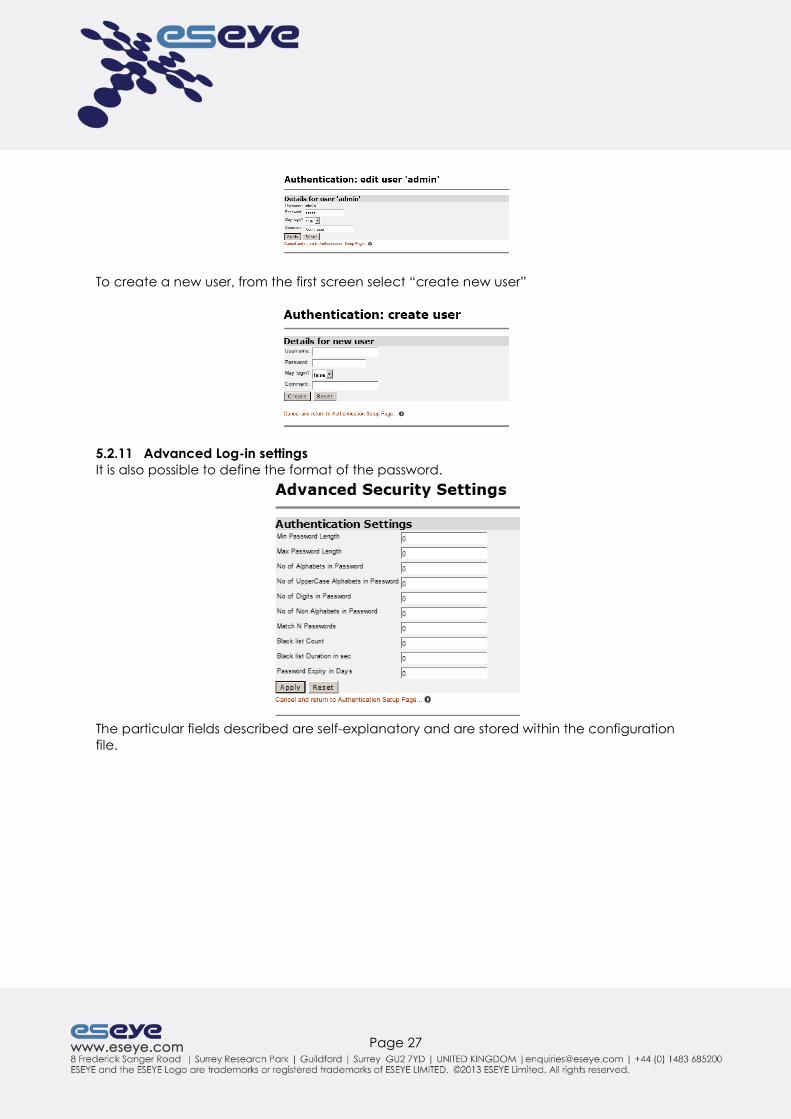
To create a new user, from the first screen select “create new user”
5.2.11 Advanced Log-in settings
It is also possible to define the format of the password.
The particular fields described are self-explanatory and are stored within the configuration
file.
Page 28
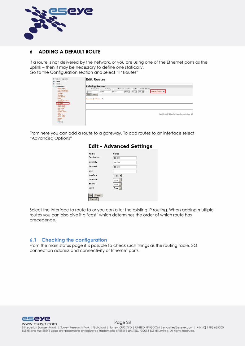
6 ADDING A DEFAULT ROUTE
If a route is not delivered by the network, or you are using one of the Ethernet ports as the
uplink – then it may be necessary to define one statically.
Go to the Configuration section and select “IP Routes”
From here you can add a route to a gateway. To add routes to an interface select
“Advanced Options”
Select the interface to route to or you can alter the existing IP routing. When adding multiple
routes you can also give it a ‘cost’ which determines the order of which route has
precedence.
6.1 Checking the configuration From the main status page it is possible to check such things as the routing table, 3G
connection address and connectivity of Ethernet ports.

Page 29
6.2 Name server resolution (DNS) To check the name servers that has been delivered to the device select “Configuration” and
“DNS Client”
Page 30
7 CLI BASIC CONFIGURATION
7.1 Changing the default LAN address The default IP address of a HERA600 router as delivered from the factory is 192.168.0.1 - you
may need to change this to suit your local network requirements.
To do so, type the following at the command prompt ip set interface iplan ipaddress 0.0.0.0 1.1.1.1
system config save
Where 0.0.0.0 is the new IP address you wish to allocate to the unit and 1.1.1.1 is the subnet.
NOTE
The specification of Subnet is optional unless different from the default. The default is
255.255.255.0. XXXX It is possible to use any of the Ethernet ports as a WAN – but this is not in
the scope of this document.
7.2 Setting an WAN username and Password, or IP address The default IP address of a HERA600 router WAN device as delivered from the factory is not
configured so you may need to change this to suit your local network requirements (or it may
be delivered automatically on configuration of the user name and password and
subsequent connection to the network).
To do so, type the following at the command prompt pppoh set transport pppoh welogin chap
pppoh set transport pppoh username benvenuto
pppoh set transport pppoh password ospite
system config save
If you have to configure the IP address and the subnet for the 3G link, type the following at
the command prompt ip set interface pppoh ipaddress 0.0.0.0 1.1.1.1
system config save
Where 0.0.0.0 is the new IP address you wish to allocate to the unit and 1.1.1.1 is the subnet.

Page 31
7.3 Adding a default route To add a default route manually, type the following at the command prompt ip add defaultroute gateway 192.168.0.1 cost 1
or
ip add defaultroute interface iplan cost 1
or
ip set defaultinterface iplan
system config save
7.3.1 Adding and altering DHCP server subnets
THE DHCP Server is pre-configured unless otherwise specified. The following script enables
and configures the server.
By default the subnet ‘iplan’ is defined already, but you may wish to add another subnet.
dhcpserver set subnet iplan2 192.168.1.0 255.255.255.0 192.168.0.10 192.168.1.250
system config save
7.4 Changing the default username and password of the Web Admin and CLI
access The default username and password of the Webserver and CLI require the user to be at the
highest login state (user = superuser). The default username and password delivered from the
factory is “admin” and “admin” and the default access level is “superuser”- you may need
to change this to suit your needs.
To do so, type the following at the command prompt
system set user admin password usefull
system set user admin access engineer
system config save
To add a new user, type the following at the command prompt system add user superuser
system set user superuser password AcC355!
system set user superuser mayconfigure enabled
system set user superuser mayconfigureweb enabled
system set user superuser maydialin disabled
system set user superuser access superuser
system config save

Page 32
8 FURTHER ADVANCED CONFIGURATION In this section we describe the more advanced features of your HERA600 product, such as
how to configure VPN connections and SIM failover strategies. We have worked hard to
make this section as easy to follow as possible however some of these advanced topics do
require some knowledge of more advanced networking topics.
8.1 CLI Advanced Firewall configuration
8.1.1 Changing the Firewall – reserved mapping via CLI
It is possible to add a reserved mapping that allows equipment to connect directly with the
external network.
The majority of reserved mappings are based on interface name.
To create a reserved mapping from an outside interface name to an internal IP address
based on the TCP/UDP port(s), enter: nat add resvmap <name>interfacename <interfacename> <intenalip> {tcp|udp} <portno> {<2ndportno>[<localportno]]]
system config save
In this command, you can configure NAPT to translate packets based on:
A single TCP/UDP port number by configuring the <portno> attributes
A range of TCP/UDP port numbers on the outside interface by configuring the <portno><2ndportno>
attributes
A range of TCP/UDP port numbers on the outside interface that translate to a range of TCP/
UDP port numbers on the inside interface by configuring the <portno> <2ndportno><localportno> <2ndlocalportno>
attributes.
Here is an example nat add resvmap item0 interfacename ipwan 192.168.0.1 udp 5100 5120 5100 5120
system config save
8.2 Simple Network Management Protocol This connection is typically used for device monitoring such as uptime, throughput and
general performance.
Settings for SNMP are only available via the CLI which is accessible via SSH or Telnet
interfaces.
It is possible to set up community names and trap destinations – you can disable and enable
the entire service as well.
It is possible to set the following
system description
system id
system location
system name
Page 33
It is also possible to enable or disable individual authentication traps when required.
9 PROVISIONING All HERA600 devices support automatic provision using TR-069(DSL Home) – which is a
standards based method of automatic configuration and management.
To use this feature, your organisation must have an ACS (Auto Configuration Server) that
supports the TR-069 standard.

Page 34
10 FIRMWARE UPDATING You HERA600 device support’s two modes of Firmware updating:
Manual updating via the web or CLI interfaces
Automatic updating from a management server
Web updating
To update the firmware image on the device you have to have been provided with an
<image>.tar file. From the webpage select “system” and “firmware upgrade” – browse to
the location of the .tar file and select “upgrade”

Page 35
11 HEALTH MONITORING AND DUAL SIM MANAGEMENT
11.1 Health Monitoring Feature The HERA600 has a sophisticated monitoring system which monitors the health and stability of
the connection in order to make decisions about such things as which SIM card to use or
whether to restart the 3 G module.
The following is a list of items that it is capable of monitoring and is checked in the following
order:
1. DNS (name) resolution – Configure 1 or more server names – for instance
http://www.bbc.co.uk. If it is unable to resolve the address then this step fails.
2. Ping to specified address - Configure 1 or more server addresses – for instance
173.194.41.78. If it receives no response then this step fails.
3. Check mobile connection status - If the PPP link (the one which runs over 3G/GRPS) is
down then this step fails. It also checks LCP echoes.
4. Check any other interface – This will check the physical status of an interface. For
example if configured to check ethernet1 and the link is physically down - nothing is
connected - then this step fails. If configured to check um1 (the mobile port) then if
radio link is down then this step fails.
Note that each of the above steps is “inherited”, meaning that for example if DNS resolution
is successful it assumes the next following 3 will also be successful. If ping is successful it
assumes the mobile link is up, etc. This is in the interest of reducing the number of tests
performed and therefore the amount of data transmitted over the link. There is an additional
option to force a ping test even though the DNS resolution has been successful.
11.2 Failover Actions The following is a list of actions that can be taken based on the checks (along with an
associated abbreviation used in the script below:
Restart system (r)
Switch to next SIM (s)
Restart 3G/GRPS ppp connection (l)
Wait for next expiry (w)
Restart internal 3G/GRPS modem (m)
Switch to next profile – (p)
Send service alarm – (a) not currently implemented
An example action would be “2l” which would restart the 3G/GRPS ppp link after 2
consecutive failures. “5r” would restart the system after 5 consecutive failures, etc. Actions
can be strung together, for instance “2l5r”

Page 36
11.3 Web page configuration
From this page is it is possible to set the various M2M parameters.
11.3.1 Web Page Configuration Steps
Set the check period
Set servers to check (for instance DNS IP addresses, interfaces etc.)
Set failure actions (if required)
Other options/variables can be set
Enable the monitoring
Save the config
Here is an example script:
m2m add check ip <ip address>
m2m set checkperiod <seconds>
m2m set enabled
system config save
To check the config please type this command
m2m show status
M2M Health Monitor Status
---------------------------
Enabled : FALSE
Status : Idle
Result : Good
Check period (s) : 150
ICMP timeout (s) : 2
DNS Auto echo test : TRUE
CnS Heartbeat : Active

Page 37
SIM1 detected : FALSE
SIM2 detected : FALSE
SIM selected : 1
Profile : 1
DNS actions :
IP actions :
IP2 actions :
IP success actions :
IP2 success actions :
PPP actions :
IF actions :
Dns check server(s)
IP check server(s)
IP2 check server(s)
PPP check server(s)
IF check server(s)
---------------------------
Number of good runs : 0
Number of bad runs : 0
---------------------------
Eseye Vendor Specific:
USSD Message Code : 126
USSD Message Type : 2
Management Server : 0.0.0.0
Management Server Port : 12400
Status Reporting Interval : 0 mins
Message Retries : 2
Message Retry Time : 30 secs
Page 38
12 ESEYE AND DATAFLEX TECHNICAL SUPPORT
If you need help with your HERA600 router please contact Eseye Dataflex technical support,
using one of the options below:
Email: [email protected]
Telephone: +44 (0) 1483685200
Raise a Ticket: http://www.eseye.com/forms/technical-support.html
The support team will most likely as you for the following information
IMEI
Product part number
Current configuration
If possible, please have a saved version of your current configuration ready to send.
If you are using Anynet connectivity please also have ready the
SIM number (starting with 8944XXXXXXXX…)
IP address, if this is known.