herz strÖmax gm/grherzmediaserver.com/data/01_product_data/01... · herz strÖmax gm/gr...
TRANSCRIPT

Page 1
HERZ STRÖMAX 4217GM/GR
HERZ STRÖMAX GM/GRSTRÖMAX-GM Circuit Control Valve with test points
STRÖMAX-GR Circuit Control ValveData sheet STRÖMAX GM/GR, Issue 1014
Dimensions in mm
Fig. NumberDN Rp L L1 H
SWHexagon
SWOctagon
kvs4217 GM 4217 GR1 4217 30 15 LF 1/2 100 71 97 27 - 0,931 4217 31 15 MF 1/2 100 71 97 27 - 3,491 4217 01 1 4217 61 15 1/2 100 71 97 27 - 6,051 4217 32 1 4217 62 20 3/4 100 71 97 32 - 6,111 4217 33 1 4217 63 25 1 120 71 107 41 - 9,221 4217 34 1 4217 64 32 1¼ 140 71 112 - 50 18,831 4217 35 1 4217 65 40 1½ 150 71 112 - 55 23,291 4217 36 1 4217 66 50 2 165 110 136 - 70 35,261 4217 07 1 4217 67 65 2½ 190 110 141 - 85 52,111 4217 08 1 4217 68 80 3 210 110 142 - 100 76,10
L
L1
SW
L1
H
Rp
Page 2
HERZ STRÖMAX 4217GM/GR
ModelsSTRÖMAX-GM Circuit Control Valve with test points, 1/2 – 3Screw down model, brass version, socket x socket, non-rising spindle, spindle seal by means of double-O-ring, pre-setting by limitation of valve lift by means of internal spindle; digital display of presetting step at the hand wheel window.2 Measuring valves are located adjacent to the hand wheel.
STRÖMAX-GR Circuit Control Valve, 1/2 – 3Screw down model, brass version, socket x socket, non-rising spindle, spindle seal by means of double-O-ring, pre-setting by limitation of valve lift by means of internal spindle; digital display of presetting step at the hand wheel window.
Other Models
4117 M DN 15 - 80 Strömax-M, Double Regulating Valves, inclined model with test points4117 R DN 15 - 80 Strömax-R, Double Regulating Valves, inclined model4117 MW DN 15 - 50 Strömax-MW, Double Regulating Valves for drinking water, inclined model with test
points Strömax-MW, Double Regulating Valves for drinking water, inclined model with test points
4117 RW DN 15 - 50 Strömax-RW, Double Regulating Valves for drinking water, inclined model4017 M DN 15 - 50 4017-M Double Regulating Valves with integral fixed orifice, inclined model with test
points4017 R DN 15 - 50 4017-R 4017-M Double Regulating Valves with integral fixed orifice, inclined model4017 MW DN 15 - 50 4017-MW Double Regulating Valves with integral fixed orifice for drinking water, incli-
ned model with test points4217 GMW DN 15 - 50 4217-GMW Double Regulating Valves for drinking water, screw-down model with test
points4000 DN 15 - 50 Herz -Metering Stations with two test points4218 GMF DN 25 - 150 Strömax-GMF, Double Regulating Valves, flanged version with test points4218 GF DN 50 - 300 Strömax-GF, Double Regulating Valves, flanged version with test points4000 + 4117-R HERZ-Metering Station + STRÖMAX-R- Double Regulating Valve4000 + 4217-GR HERZ-Metering Station + STRÖMAX-GR- Double Regulating Valve4000 F + 4218 GMF HERZ-Stainless Steel Orifice Plates + STRÖMAX-GMF Double Regulating Valves,
flanged version with test points4000 F + 4218 GF HERZ-Stainless Steel Orifice Plates + STRÖMAX-GF Double Regulating Valves,
flanged version with test points4000 F DN 65 - 300 Herz -Stainless Steel Orifice Plates
Test points2 test points are located adjacent to the hand wheel at identical angles, sealed by the manufacturer. This arrangement permits optimum access and connection of measuring instruments in any position of installation.
Field of Application
For hydraulic balancing in heating and cooling systems, adjustment of distribution mains, circuits, heat exchangers, heating and cooling registers, etc.
Technical data
Close the valve clockwise Max. operating temperature 130 °C (up to DN32) Max. operating temperature 110 °C (from DN40) Max. operating pressure 16 bar
Water purity in accordance with the OeNORM H5195 and VDI 2035 standards.Ethylene and propylene glycol can be mixed to a ratio of 25 - 50 vol. [%].HERZ compression adapters for copper and steel pipes, allowable temperature and pressure ratings according to EN 1254-2 1998 Table 5.HERZ plastic pipe connections max. operating temperature 95 ° C and max. operating pressure 10 bar, if approved by the pipe manufacturer.Ammonia contained in hemp can damage brass valve bodies, EPDM gaskets can be affected by Mineral oils lubricants and thus lead to failure of the EPDM seals. Please refer to manufacturers documentation when using ethylene glycol products for frost and corrosion protection.

Page 3
HERZ STRÖMAX 4217GM/GR
Pipe Connection
The sockets for the circuit control valves R = 1/2“ and R = 3/4“ are suitable for connecting either threaded pipes or ca-librated soft-steel or copper pipes, the latter two by means of adapters and compression unions. Compression unions and adapters must be ordered separately.
Pipe Ø D mm 10 12 14 15 16 18 18
Valve R = 1/2 3/4
Adapter Order No 1 6272 01 1 6272 01 1 6272 01 1 6272 01 1 6272 01 1 6272 11 1 6272 12
Compr. Union Order No 1 6284 00 1 6284 01 1 6284 03 1 6284 04 1 6284 05 1 6289 01 1 6289 01
For the installation of soft-steel or copper pipes with compression unions, we recommend the use of support sleeves. For perfect installation lubricate the thread of the locking nut (male or female thread) as well as the olive with silicone oil.Please consult our instructions for installation.
Plastic Pipe ConnectionThe circuit control valves R = 1/2“ are suitable for systems with plastic pipes. Adapters and plastic pipe unions are connected to the sockets. For models and dimensions consult the HERZ catalogue.
Flow Direction
During installation, take into account the flow direction arrow on the valve body.
Installation Position
The non-rising valve spindle arranged perpendicular to the valve axis guarantees optimumaccessibility and optimum valve operation in any installation position.
Presetting
The current position of the flow restriction cone is shown on a clearly visible digital display on the front side of the hand wheel. The desired presetting step can be easily adjusted and secured by means of the covered presetting spindle loca-ted inside the valve. The preset circuit control valve can be shut off at any time and/or can be set to any desired position below the fixed presetting. The presetting spindle is covered by the hand wheel fastening screw and thus protected against unauthorized operation.
Preset Sealing
The presetting seal (1 6517 04) is attached above the hand wheel fastening screw to preventunauthorized operation. If the seal is removed it breaks and cannot be mounted again. There-fore, it can be clearly seen whether tampering with the valve has occurred.
Presetting Marker
The pre-setting marker (1 6517 05) is fastened as a tag above the valve or pipe. The setting of therespective valve is marked by cutting or breaking off the teethc at the figures for full and partial turns.This permits checking and/or restoration of the original pre-setting made on the occasion of thesystem set-up after servicing without having to rely on documentation.
STRÖMAX-GR
STRÖMAX-GR valves are of the same mechanical design as STRÖMAX-GM, i.e. the digital presetting step display as well as the presetting procedure are identical. However, STRÖMAX-GR valves are not equipped with measuring valves.
Differential Pressure Measurement - STRÖMAX-GM
The STRÖMAX-GM circuit control valve is equipped with two test points. The differential pressure can be measured using a suitable measuring instrument, which permits calculation of the flow rate as a function of the respective preset-ting step. The HERZ-Measuring computer (1 8900 04) permits direct flow rate reading (consult the equipment manual).

Page 4
HERZ STRÖMAX 4217GM/GR
Presetting
The STRÖMAX-GM and STRÖMAX-GR circuit control valves are supplied in open position, preset to permit the maxi-mum possible valve lift. The hand wheel mechanism is adjusted in such a way that the digital reading will be 0.0 when the valve is closed.
Presetting Procedure
1. Set to the desired step according to calculation (digital display ont the hand wheel).2. Remove the hand wheel locking screw, do not remove the hand wheel from the valve.3. Screw the presetting spindle, which is now accessible, in up to the stop.4. Screw in the hand wheel locking screw again.5. Seal with presetting seal.6. Mark the step set at the presetting marker and attach the marker to the valve.
Points 5 and 6 are not necessary for function, but are recommended. When using a differential manometer, setting can be performed only on the basis of the HERZ-setting diagrams. A flowrate for the STRÖMAX-GM valve can only be set without specifying a pre-setting step if a measuring instrument is used. Follow the operating instructions when using a measuring computer.
Digital Display
The factory setting of the digital display is 0.0 when the valve is closed. If the complete hand wheel (rotating grip, figure wheels, base plate) is removed from the valve or if a defective part has to be replaced, proceed as follows to ensure correct digital display reading:
1. Return the complete hand wheel into position and slide it onto the valve until the hexagon at the valve body and the spindle gear interlock.
2. Shut the valve by turning clockwise.3. If the digital display reads 0.0 in the shut position, the hand wheel has been positioned correctly and can be secured
by means of the locking screw. In case of a different reading remove the complete hand wheel.4. Twist the base plate and rotating grip until the digital display reads 0.0 and then return the complete hand wheel into
position without twisting the spindle.5. Tighten hand wheel locking screw.
Then, the valve can be set to the desired position.
Accessories and Spare Parts
1 6517 04 Pre-setting seal1 6517 05 Pre-setting marker1 8900 04 HERZ measuring computer for one-handed operation1 6387 xx STRÖMAX-GM/GR upper part – refer to the HERZ catalogue for order numbers1 6517 06 Hand wheel for valve dimension 1/2“ – 11/2“1 6517 08 Hand wheel for valve dimension 2“ – 3“1 0284 01 Test points, brass version, blue cap (return)1 0284 02 Test points, brass version, red cap (supply)1 0284 03 Test points with capillary connection, brass version, blue cap (return)1 0284 04 Test points with capillary connection, brass version, red cap (supply)1 0284 11 Test points, brass version, blue cap (return). Extended model for insulated valves1 0284 12 Test points, brass version, red cap (supply). Extended model for insulated valves1 0284 21 Test points with draining function, brass version, blue cap (return), with swivel hose connection1 0284 22 Test points with draining function, brass version, red cap (supply), with swivel hose connection1 0284 23 Extended test point, drain function, blue cap1 0284 24 Extended test point, drain function, blue cap
Page 5
HERZ STRÖMAX 4217GM/GR
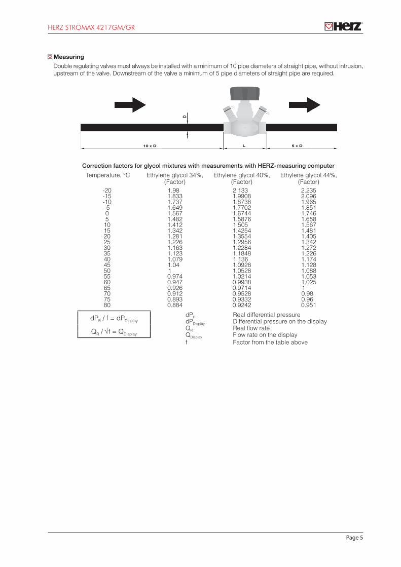
Measuring
Double regulating valves must always be installed with a minimum of 10 pipe diameters of straight pipe, without intrusion, upstream of the valve. Downstream of the valve a minimum of 5 pipe diameters of straight pipe are required.
10 x D 5 x DL
D
Correction factors for glycol mixtures with measurements with HERZ-measuring computer
Temperature, °C Ethylene glycol 34%, (Factor)
Ethylene glycol 40%, (Factor)
Ethylene glycol 44%, (Factor)
-20 1.98 2.133 2.235-15 1.833 1.9908 2.096-10 1.737 1.8738 1.965-5 1.649 1.7702 1.8510 1.567 1.6744 1.7465 1.482 1.5876 1.65810 1.412 1.505 1.56715 1.342 1.4254 1.48120 1.281 1.3554 1.40525 1.226 1.2956 1.34230 1.163 1.2284 1.27235 1.123 1.1848 1.22640 1.079 1.136 1.17445 1.04 1.0928 1.12850 1 1.0528 1.08855 0.974 1.0214 1.05360 0.947 0.9938 1.02565 0.926 0.9714 170 0.912 0.9528 0.9875 0.893 0.9332 0.9680 0.884 0.9242 0.951
dPR / f = dPDisplaydPR Real differential pressuredPDisplay Differential pressure on the display
QR / √f = QDisplayQR Real flow rateQDisplay Flow rate on the displayf Factor from the table above

Page 6
HERZ STRÖMAX 4217GM/GR
HERZ-Standard diagram STRÖMAX-GM
Order No 1 4217 30 DN 15 LF
100111,010,0100,0
10
100
1
3,5
2,5
24
3
0,05
50
5
500
50,5
50
1,5
0,5
5
0,005
6
10,1
1
000.01000.1001011
[mba
r]
[kP
a]
[kg/h]
0,5 5
000505 5005
6
10,10,010,0010,0001 [kg/s] 0,50,005 0,050,0005
kv-value
pre
ssu
re d
rop
∆p
flowrate qm

Page 7
HERZ STRÖMAX 4217GM/GR
HERZ-Standard diagram STRÖMAX-GM
Order No 1 4217 31 DN 15 MF
100111,010,0100,0
10
100
1
3,5
2,5
2
4
3
0,05
50
5
500
50,5
50
1,5
0,5
5
0,005
6
10,1
1
000.01000.1001011
[mba
r]
[kP
a]
[kg/h]
0,5 5
000505 5005
10,10,010,0010,0001 [kg/s] 0,50,005 0,050,0005
kv-value
pre
ssu
re d
rop
∆p
flowrate qm

Page 8
HERZ STRÖMAX 4217GM/GR
HERZ-Standard diagram STRÖMAX-GM • STRÖMAX-GR
Order No 1 4217 01 • 1 4217 61 DN 15
100111,010,0
10
100
1
3,5
2,52
4
3
0,05
50
5
500
50,5
50
1,5
0,5
5
6
10,1
1
000.01000.100101
[mba
r]
[kP
a]
[kg/h]
0,5 5
50 5000500
10,10,01[kg/s] 0,005 0,50,05
kv-value
pre
ssu
re d
rop
∆p
flowrate qm

Page 9
HERZ STRÖMAX 4217GM/GR
HERZ-Standard diagram STRÖMAX-GM • STRÖMAX-GR
Order No 1 4217 32 • 1 4217 62 DN 20
10111,010,0100,0
10
100
5
50 500
50
0,005 50,50,05
0,5
2,52
1,51
3
654
3,5
0,10,01
0,1
1
000.01000.1001011
[kP
a]
[kg/h]
0,5
0,5 5
0,05
00505 5.0005
10,10,010,0010,0001 [kg/s] 0,50,005 0,050,0005
kv-value
pre
ssu
re d
rop
∆p
flowrate qm

Page 10
HERZ STRÖMAX 4217GM/GR
HERZ-Standard diagram STRÖMAX-GM • STRÖMAX-GR
Order No 1 4217 33 • 1 4217 63 DN 25
100
10000111,010,0100,0
10
100
0,51
1,52
5
50 500
50
0,05 50,5
32,5
3,5
0,005
45678
0,1
1
10
0,01
0,1
1
000.01000.1001011
[kP
a]
[kg/h]
0,5
0,5 5
0,05
50 500 5.0005
10,10,010,0010,0001 [kg/s] 0,50,005 0,050,0005
kv-value
pre
ssu
re d
rop
∆p
flowrate qm

Page 11
HERZ STRÖMAX 4217GM/GR
HERZ-Standard diagram STRÖMAX-GM • STRÖMAX-GR
Order No 1 4217 34 • 1 4217 64 DN 32
10
100
10000010111,010,0
1
10
100
5
50 500
50
0555,050,0
0,5
3
5
2,52
1,51 4
6
87
9
0,1
1
10
0,01
0,1
1
000.001000.01000.100101
[mba
r]
[kP
a]
[kg/h]
0,5
0,5 5
0,05
000.05000.500505
1010,10,010,001 [kg/s] 50,05 0,50,005
kv-value
pre
ssu
re d
rop
∆p
flowrate qm
Page 12
HERZ STRÖMAX 4217GM/GR
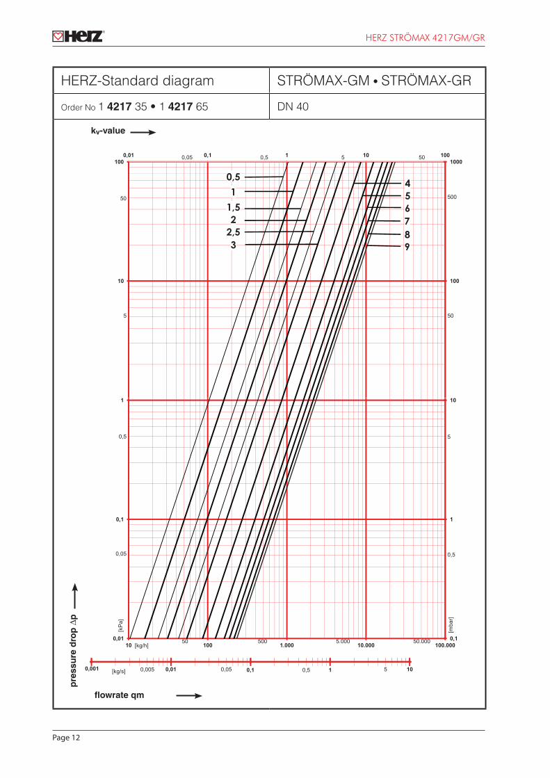
HERZ-Standard diagram STRÖMAX-GM • STRÖMAX-GR
Order No 1 4217 35 • 1 4217 65 DN 40
10
100
10000010111,010,0
1
10
100
5
50 500
50
0555,050,0
0,5
3
5
2,52
1,51
4
6
89
7
0,1
1
10
0,01
0,1
1
000.001000.01000.100101
[mba
r]
[kP
a]
[kg/h]
0,5
0,5 5
0,05
000.05000.500505
1010,10,010,001 [kg/s] 50,05 0,50,005
kv-value
pre
ssu
re d
rop
∆p
flowrate qm

Page 13
HERZ STRÖMAX 4217GM/GR
HERZ-Standard diagram STRÖMAX-GM • STRÖMAX-GR
Order No 1 4217 36 • 1 4217 66 DN 50
1
100010111,010,0
1
10
100
0,51
1,52
5
50 500
50
0,05 055
3,53
2,5
54
67
0,5
0,1
1
0,01
0,1
1
000.001000.01000.100101
[mba
r]
[kP
a]
[kg/h]
0,5
0,5 5
0,05
500 5.000 50.00050
1010,10,010,001 [kg/s] 50,05 0,50,005
kv-value
pre
ssu
re d
rop
∆p
flowrate qm
Page 14
HERZ STRÖMAX 4217GM/GR
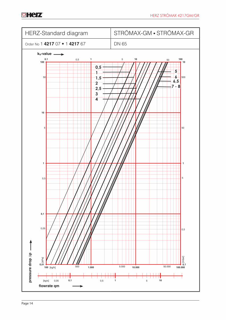
HERZ-Standard diagram STRÖMAX-GM • STRÖMAX-GR
Order No 1 4217 07 • 1 4217 67 DN 65
100010111,0
10
100
0,511,52
5
50 500
50
0,5 5 50
432,5
65
6,57 - 8
0,1
1
0,01
0,1
1
000.001000.01000.1001
[mba
r]
[kP
a]
[kg/h]
0,5
0,5 5
0,05
000.05000.5005
1010,1[kg/s] 0,05 50,5
kv-value
pre
ssu
re d
rop
∆p
flowrate qm

Page 15
HERZ STRÖMAX 4217GM/GR
HERZ-Standard diagram STRÖMAX-GM • STRÖMAX-GR
Order No 1 4217 08 • 1 4217 68 DN 80
100010111,0
10
100
0,51
1,52
5
50 500
50
0,5 5 50
43
6,56
85 7
0,1
1
0,01
0,1
1
000.001000.01000.1001
[mba
r]
[kP
a]
[kg/h]
0,5
0,5 5
0,05
500 000.005000.5
1010,1[kg/s] 0,05 50,5
kv-value
pre
ssu
re d
rop
∆p
flowrate qm

Page 16
HERZ STRÖMAX 4217GM/GR
SettingDN
15LFDN
15MFDN 15 DN 20 DN 25 DN 32 DN 40 DN 50 DN 65 DN 80
0,5 0,05 0,33 0,44 0,35 0,67 0,79 1,04 0,88 5,58 10,89
0,6 0,06 0,34 0,47 0,37 0,71 0,86 1,15 1,00 6,31 12,34
0,7 0,06 0,36 0,50 0,39 0,76 0,93 1,26 1,12 7,04 13,79
0,8 0,07 0,37 0,52 0,41 0,81 1,00 1,38 1,24 7,76 15,25
0,9 0,07 0,39 0,55 0,43 0,85 1,08 1,49 1,36 8,49 16,70
1,0 0,08 0,40 0,58 0,45 0,90 1,15 1,60 1,48 9,22 18,15
1,1 0,09 0,44 0,64 0,51 0,98 1,28 1,76 1,77 9,89 18,96
1,2 0,10 0,47 0,69 0,57 1,06 1,41 1,91 2,06 10,57 19,78
1,3 0,11 0,51 0,75 0,63 1,14 1,55 2,06 2,35 11,24 20,59
1,4 0,12 0,54 0,80 0,69 1,22 1,68 2,21 2,65 11,91 21,40
1,5 0,13 0,58 0,86 0,75 1,30 1,82 2,36 2,94 12,58 22,21
1,6 0,14 0,61 0,92 0,81 1,38 1,95 2,51 3,23 13,25 23,02
1,7 0,15 0,65 0,97 0,87 1,46 2,08 2,66 3,52 13,92 23,84
1,8 0,16 0,69 1,03 0,93 1,54 2,22 2,81 3,81 14,60 24,65
1,9 0,17 0,72 1,09 0,99 1,62 2,35 2,96 4,10 15,27 25,46
2,0 0,18 0,76 1,14 1,05 1,70 2,48 3,11 4,39 15,94 26,27
2,1 0,19 0,83 1,28 1,17 1,83 2,70 3,35 4,93 16,48 26,90
2,2 0,20 0,90 1,41 1,30 1,96 2,91 3,58 5,47 17,02 27,53
2,3 0,21 0,97 1,54 1,42 2,08 3,12 3,81 6,02 17,56 28,16
2,4 0,23 1,05 1,67 1,54 2,21 3,33 4,05 6,56 18,10 28,79
2,5 0,24 1,12 1,80 1,66 2,34 3,55 4,28 7,10 18,64 29,42
2,6 0,25 1,19 1,93 1,78 2,47 3,76 4,51 7,64 19,18 30,05
2,7 0,26 1,26 2,06 1,90 2,60 3,97 4,75 8,18 19,72 30,68
2,8 0,27 1,34 2,19 2,03 2,73 4,19 4,98 8,72 20,26 31,30
2,9 0,28 1,41 2,32 2,15 2,86 4,40 5,21 9,27 20,81 31,93
3,0 0,30 1,48 2,45 2,27 2,99 4,61 5,45 9,81 21,35 32,56
3,1 0,31 1,58 2,69 2,46 3,13 4,87 5,76 10,57 22,14 33,55
3,2 0,32 1,67 2,92 2,65 3,28 5,13 6,08 11,33 22,92 34,53
3,3 0,33 1,77 3,16 2,85 3,42 5,39 6,40 12,09 23,71 35,52
3,4 0,35 1,86 3,40 3,04 3,57 5,66 6,72 12,85 24,50 36,50
3,5 0,36 1,96 3,63 3,23 3,72 5,92 7,03 13,61 25,29 37,49
3,6 0,37 2,05 3,87 3,42 3,86 6,18 7,35 14,37 26,08 38,47
3,7 0,39 2,15 4,11 3,61 4,01 6,44 7,67 15,13 26,87 39,46
3,8 0,40 2,25 4,34 3,80 4,16 6,70 7,99 15,89 27,66 40,44
3,9 0,41 2,34 4,58 3,99 4,30 6,96 8,30 16,65 28,44 41,43
4,0 0,42 2,44 4,81 4,19 4,45 7,22 8,62 17,41 29,23 42,41
4,1 0,45 2,51 4,89 4,30 4,61 7,57 9,01 18,29 30,21 43,41
4,2 0,47 2,59 4,98 4,41 4,78 7,91 9,39 19,17 31,18 44,42
4,3 0,49 2,67 5,06 4,53 4,94 8,26 9,78 20,06 32,16 45,42
4,4 0,52 2,74 5,14 4,64 5,11 8,60 10,17 20,94 33,13 46,43
4,5 0,54 2,82 5,22 4,76 5,27 8,95 10,55 21,82 34,11 47,43
4,6 0,56 2,89 5,30 4,87 5,44 9,29 10,94 22,71 35,08 48,44
4,7 0,59 2,97 5,38 4,98 5,60 9,64 11,33 23,59 36,06 49,44
4,8 0,61 3,04 5,46 5,10 5,77 9,99 11,71 24,47 37,03 50,44
4,9 0,63 3,12 5,54 5,21 5,93 10,33 12,10 25,36 38,01 51,45
5,0 0,66 3,20 5,62 5,32 6,10 10,68 12,49 26,24 38,98 52,45

Page 17
HERZ STRÖMAX 4217GM/GR
SettingDN
15LFDN
15MFDN 15 DN 20 DN 25 DN 32 DN 40 DN 50 DN 65 DN 80
5,1 0,68 3,23 5,67 5,40 6,23 11,02 12,86 26,76 39,78 53,28
5,2 0,71 3,26 5,71 5,48 6,36 11,36 13,23 27,29 40,57 54,10
5,3 0,74 3,29 5,75 5,56 6,49 11,70 13,60 27,81 41,37 54,93
5,4 0,77 3,32 5,79 5,64 6,62 12,04 13,97 28,33 42,16 55,75
5,5 0,79 3,35 5,84 5,72 6,75 12,38 14,34 28,85 42,95 56,58
5,6 0,82 3,37 5,88 5,80 6,88 12,72 14,71 29,37 43,75 57,40
5,7 0,85 3,40 5,92 5,88 7,01 13,06 15,09 29,90 44,54 58,23
5,8 0,88 3,43 5,97 5,96 7,14 13,40 15,46 30,42 45,34 59,05
5,9 0,91 3,46 6,01 6,03 7,28 13,74 15,83 30,94 46,13 59,88
6,0 0,93 3,49 6,05 6,11 7,41 14,08 16,20 31,46 46,93 60,70
6,1 7,51 14,33 16,46 31,84 47,44 61,54
6,2 7,62 14,58 16,72 32,22 47,96 62,37
6,3 7,72 14,83 16,98 32,60 48,48 63,21
6,4 7,82 15,09 17,24 32,98 48,99 64,05
6,5 7,93 15,34 17,49 33,36 49,51 64,88
6,6 8,03 15,59 17,75 33,74 50,03 65,72
6,7 8,14 15,85 18,01 34,12 50,55 66,55
6,8 8,24 16,10 18,27 34,50 51,06 67,39
6,9 8,35 16,35 18,53 34,88 51,58 68,22
7,0 8,45 16,61 18,79 35,26 52,10 69,06
7,1 8,53 16,71 19,06 52,10 69,76
7,2 8,61 16,81 19,33 52,10 70,47
7,3 8,68 16,91 19,59 52,10 71,17
7,4 8,76 17,01 19,86 52,10 71,87
7,5 8,84 17,11 20,13 52,10 72,58
7,6 8,91 17,21 20,40 52,10 73,28
7,7 8,99 17,30 20,67 52,10 73,99
7,8 9,07 17,40 20,94 52,11 74,69
7,9 9,14 17,50 21,20 52,11 75,40
8,0 9,22 17,60 21,47 52,11 76,10
8,1 17,73 21,65
8,2 17,85 21,84
8,3 17,97 22,02
8,4 18,09 22,20
8,5 18,21 22,38
8,6 18,34 22,56
8,7 18,46 22,74
8,8 18,58 22,92
8,9 18,70 23,10
9,0 18,83 23,29
Please note: all diagrams are indicative in nature and do not claim to be complete.All specifications and statements within this document are according to information available at the time of printing and meant for informational purpose only. Herz Armaturen reserves the right to modify and change products as well as its technical specifications and/or it functioning according to technological progress and requirements. It is understood that all im-ages of Herz products are symbolic representations and therefore may visually differ from the actual product. Colours may differ due to printing technology used. In case of any further questions don’t hesitate to contact your closest HERZ Branch-office.