heterotypic tumor models through freeform printing into
TRANSCRIPT

BiomaterialsScience
PAPER
Cite this: Biomater. Sci., 2021, 9,4496
Received 11th April 2021,Accepted 7th May 2021
DOI: 10.1039/d1bm00574j
rsc.li/biomaterials-science
Heterotypic tumor models through freeformprinting into photostabilized granular microgels†
Thomas G. Molley, a Gagan K. Jalandhra,a Stephanie R. Nemec,a
Aleczandria S. Tiffany,b Amrutha Patkunarajah,e Kate Poole, e
Brendan A. C. Harley, b,c,d Tzong-tyng Hungf and Kristopher A. Kilian *a,g
The tissue microenvironment contains a complex assortment of multiple cell types, matrices, and vessel
structures, which is difficult to reconstruct in vitro. Here, we demonstrate model tumor microenviron-
ments formed through direct writing of vasculature channels and tumor cell aggregates, within a cell-
laden microgel matrix. Photocrosslinkable microgels provide control over local and global mechanics,
while enabling the integration of virtually any cell type. Direct writing of a Pluronic sacrificial ink into a
stromal cell-microgel suspension is used to form vessel structures for endothelialization, followed by
printing of melanoma aggregates. Tumor cells migrate into the prototype vessels as a function of spatial
location, thereby providing a measure of invasive potential. The integration of perfusable channels with
multiple spatially defined cell types provides new avenues for modelling development and disease, with
scope for both fundamental research and drug development efforts.
1 Introduction
Tumor progression and dissemination are influenced throughlocal microenvironment mechanics and degradability,1 surfacetopology,2,3 and paracrine and autocrine signaling betweentumor cells and surrounding stroma.4–6 Within this complexmicroenvironment, blood and lymphatic vessels play criticalroles in feeding the primary tumor, while also providing anavenue for dissemination through intravasation and extravasa-tion.7 While simple co-culture models from transwell plates,8
monolayers,9 3-dimensional (3D) spheroid co-cultures,10 andcell-embedded hydrogel matrices11 have yielded great insightsinto tumor-stroma and vasculature interactions, considerable
work remains to realize full spatiotemporal control in 3D—anessential task for understanding the functional relationshipsof cells, stroma, and molecular interactions in this multi-variate space. And given the complexity of the signaling under-lying tumor progression, creation of robust models that assem-ble multiple cell types in vitro has remained a challenge.12
3D bioprinting has emerged as a promising tool to attenu-ate the spatiotemporal properties of cells and their surround-ing matrices to build better tissue models for fundamentalresearch and drug development. Recently, printing intosupport baths of suspended microgels has garnered consider-able attention as a route to fabricating complex tissuemimics.13–19 These support baths fluidize under shear force asthe microgel particles near the print nozzle translate aroundthe tip, while subsequently supporting the ink that is de-posited. This enables the freeform printing of inks in alldimensions, allowing for complex structures and tallerprints.20 Concurrently, Lewis and colleagues created the firstmethod for directly writing vasculature through sacrificial inksto create vascularized hydrogels21,22 and they have furtherextended this work to printing into a support bath of orga-noids to form thick vascularized tissues.23,24 These approacheshave demonstrated the versatility of printing in granularmedia, and the potential to fabricate defined vessel structures.
Here, we present freeform vascular printing in cell-ladenmicrogel suspensions where a sacrificial ink deposited withinphotocrosslinkable microgels defines hollow channels amidstprinted cancer and stromal structures. The platforms modular-ity enables virtually any combination of cells to be spatially
†Electronic supplementary information (ESI) available. See DOI: 10.1039/d1bm00574j
aSchool of Materials Science and Engineering, University of New South Wales,
Sydney, NSW 2052, Australia. E-mail: [email protected] of Chemical and Biomolecular Engineering, University of Illinois at
Urbana-Champaign, Urbana, IL 61801, USAcCancer Center at Illinois, University of Illinois at Urbana-Champaign, Urbana,
IL 61801, USAdCarl R. Woese Institute for Genomic Biology, University of Illinois at Urbana-
Champaign, Urbana, IL 61801, USAeEMBL Australia Node in Single Molecule Science, School of Medical Sciences,
Faculty of Medicine & Health, University of New South Wales, Sydney, NSW 2052,
AustraliafBiological Resources Imaging Laboratory, Mark Wainwright Analytical Centre,
University of New South Wales, Sydney, NSW 2052, AustraliagSchool of Chemistry, Australian Centre for Nanomedicine, University of New South
Wales, Sydney, NSW 2052, Australia
4496 | Biomater. Sci., 2021, 9, 4496–4509 This journal is © The Royal Society of Chemistry 2021
Publ
ishe
d on
10
May
202
1. D
ownl
oade
d by
UN
SW L
ibra
ry o
n 6/
22/2
021
6:23
:59
AM
.
View Article OnlineView Journal | View Issue

defined within controlled proximity to prototype vascularchannels. As proof of principle of our systems versatility, wedemonstrate the granular gels capacity to model tumor pro-gression by spatially organizing three important contributors:(1) stromal cells dispersed uniformly within the microgel sus-pension, (2) primary tumor cells and structures in defined 3Darchitectures, and (3) endothelial cells within interpenetratinghollow channels (Fig. 1A). Further microenvironment controlis afforded by changing the microgel composition and chem-
istry, facilitating tunable local and global mechanics of themicrogel construct.
2 Results2.1 Creating photocrosslinkable support gels
In contrast to dissolvable gelatin microparticles used in pre-vious work,15,16 we synthesized gelatin–methacryloyl (GelMa)microparticles using a water-in-oil emulsion; liquid GelMa isadded dropwise to 40 °C oil under stirring followed by coolingto 10 °C to physically crosslink the microparticles, leavingmethacryloyl moieties for further crosslinking. Adding acetonethen dehydrates the microparticles and allows for easywashing and weighing. When rehydrated, the microparticleshave an approximate diameter of 100 microns (Fig. 2A). Sinceyield stress fluid properties can vary greatly with small changesin suspension compositions, we weighed and hydrated ourdried microparticles with consistent particle to liquid ratios.These suspensions were rested for at least 24 hours prior touse since acetone dried GelMa can take days to rehydrate(Fig. S1†). At hydrated volume fractions of ∼50–65%, themicroparticles reach a jammed state where they lock in placeby frictional and repulsion forces.20 These jammed particlesuspensions behave as a solid under equilibrium conditionsbut will flow like a liquid once a critical shear force is applied.Swelling tests of the GelMa microparticles showed they rehy-drate to ∼10× their dried weight, which we used to hydrate oursuspensions to the target 60% volume fraction of particlesconsistently.
By functionalizing the gelatin with methacryloyl groups,our microparticle suspensions can be chemically crosslinkedwithin and between the particles to stabilize the matrix. Afterexposure to 60 seconds of 395 nm light on a rheometer, themicrogels gain a 2 order of magnitude increase in storagemodulus (Fig. 2B) and become stable under shear forces(Fig. S2A†). To gain greater control of the local mechanics ofthe gel as well as aid in printability, we added a fraction ofsoluble GelMa to provide a means of effectively “stitching” thejammed suspension together after printing. By hydrating thedried particles with a liquid solution of low weight percentGelMa, the same bulk rheological properties of the microgelsuspension can be maintained, while now creating a softmatrix around the stiff particles. When hydrating the particlesto 40% volume fraction with a 1 wt% GelMa solution as theliquid filler, we achieve near identical bulk mechanical pro-perties to the jammed microparticles (no filler) while changingthe interstitial space from pure liquid to a soft matrix (Fig. 2B).When applying a shear strain rate sweep on the suspensions,both exhibit similar yield stress fluid properties—each demon-strating high printability. Suspension with fillers also demon-strate stability under shear forces once photocrosslinked(Fig. S2A†). Decreasing the light exposure had minimal effecton the gel strength of filler suspensions with a <1% decreasein storage modulus; however, increasing light exposure to 120seconds gave a 23% increase (Fig. S2B†). Stabilized suspen-
Fig. 1 Photocrosslinking to stabilize suspension microgels allows forcomplex organization of cells in three distinct ways. (A) (1) An uncross-linked microgel suspension, with or without cells, is placed in a reactorwhere a sacrificial ink is freeformly printed. (2) More cell types canfurther be printed as different shapes and sizes at various proximities tothe sacrificial ink. (3) The suspension is photocrosslinked followed byremoval of the sacrificial ink and subsequent seeding of endothelial cellson the hollow channel walls. (B) Macro images of the three stages ofhollow channel formation: printing of the ink, photocrosslink and eva-cuation of the ink, and perfusion of the hollow channel for seeding. (C)A macro image of a 7 mm tall spiral print of Pluronic F127 ink in microgelsuspension. (D) An image of blue dye that has been perfused throughthe letters “UNSW” that were printed and evacuated. Scale bars: 5 mm(B, C and D).
Biomaterials Science Paper
This journal is © The Royal Society of Chemistry 2021 Biomater. Sci., 2021, 9, 4496–4509 | 4497
Publ
ishe
d on
10
May
202
1. D
ownl
oade
d by
UN
SW L
ibra
ry o
n 6/
22/2
021
6:23
:59
AM
. View Article Online

sions warmed to 37 °C where the physical crosslinks releasehad a drop in strength of only 7% (Fig. S2C†), demonstratingstability of the network through the covalent modifications.The bulk mechanical properties can also be tuned by varyingthe weight percentage of the GelMa used to make the microgelsuspension, where particles formed with 15 wt% GelMaformed suspensions with a 70% higher storage modulus(Fig. S3†).
It is well appreciated that both global and local mechanicalenvironments can play a large role in directing cell functionand behavior.25,26 Therefore, multiple classes of mechanical
testing are required for this type of heterogeneous microgelsuspension. To highlight this heterogeneity, we melted a sus-pension solution prior to photocrosslinking and found adecrease in strength of nearly two orders of magnitude(Fig. 2D). We further demonstrate this heterogeneity with AFMforce curves (1 μm radius spherical borosilicate probe, 36curves per 10 μm × 10 μm regions) taken at 4 differentlocations across the surface of our crosslinked microgel. Theregions over the microparticles have relative moduli of over 5times that of the filler regions (Fig. 2E). However, even over thestiffer particles, there is wide variation at the local scale as the
Fig. 2 Characterization of GelMa microparticle support suspensions for 3D printing. (A) Size distribution (n = 100) of the 10 wt% GelMa microparti-cles. Inset image is a representative optical image of the microparticles. (B) Rheological analysis of the gelation of suspensions with (red markers)and without (black markers) a 1 wt% GelMa filler in the liquid phase. Closed markers are the storage modulus (G’) and open markers are the lossmodulus (G’’) The yellow bar indicates UV crosslinking. (C) Uncrosslinked microgel viscosity as a function of Shear rate for suspensions with (redmarkers) and without (black markers) filler. (D) Effect of melting a microgel suspension (red markers) on the storage modulus (G’) when compared tounmelted heterogenous suspension (black markers). The yellow bar indicates UV crosslinking. (E) Contact mode atomic force microscopy (AFM) over4 regions of a suspension bath surface. Force curves (n = 36 per square, p < 0.001) were taken at each 10 μm × 10 μm region of the surface wherethe analyzed young’s modulus is plotted for each region’s curves. (F) Z-stack projections (100 μm z-stacks of 50 slices) of ADSCs stained withHoechst (blue) and Phalloidin (green) in microgel suspensions and a pure hydrogel (10 wt% GelMa). (G) Box plots of cell volume quantification ofmicrogel suspensions vs. pure hydrogels over 7 days (*** = p < 0.001, ** = p < 0.0001). Scale bars: 10 μm (E), 100 μm (F).
Paper Biomaterials Science
4498 | Biomater. Sci., 2021, 9, 4496–4509 This journal is © The Royal Society of Chemistry 2021
Publ
ishe
d on
10
May
202
1. D
ownl
oade
d by
UN
SW L
ibra
ry o
n 6/
22/2
021
6:23
:59
AM
. View Article Online
filler material wraps itself not only between particles, butaround them as well, creating broad variability in stiffness thecell experiences. This contrasts with similar microporous par-ticle scaffold (MAP) systems that contain discrete pockets ofheterogeneity.20
We next set out to explore the exciting possibility that ourprinting support matrix would be beneficial to integrated livecells. We began by seeding adipose derived stem cells (ADSCs)at one million cells per ml of microgel suspension. Initial live/dead staining of cells indicated high cell viability (Fig. S4†).However, the nature of the scaffolds made it difficult to imagesamples thicker than 0.5 mm. The particles have a muchhigher index of refraction compared to the filler phase, thusleading to significant light scattering during imaging. To cir-cumvent this limitation, we adapted our recently reportedoptical clearing technique27,28 where index matching allowsincreased imaging depth with minimal light scattering(Fig. S5†). To evaluate our clearing and imaging protocol, weloaded one million ADSCs per ml into our suspension, with apure bulk GelMa matrix of comparable mechanics as a com-parison. Given the porous nature of the microgels, and the ten-dency for cells to spread anisotropically in 3D, we sought tocompare cell volume and surface area in 3D rather than with2D projections. High resolution z-stacks of cells stained withphalloidin and Dapi were imported into Imaris to segment thecell and nuclear volumes (Fig. S6A†). There are increasinglysignificant differences of cell volume between our suspensionand bulk GelMa on days 1, 3 and 7 (day 1 p < 0.001; day 3, 7 p= 0.0001) with the suspension cells increasing volume by∼100% from day 1 to 7 (p = 0.001) (Fig. 2G). A homogenousbulk GelMa matrix of comparable stiffness is dense and con-stricting to embedded cells, causing them to adopt a stellatemorphology as they extend protrusive features and attempt todegrade the surrounding matrix. While no significant differ-ence in cell volume was found across any days for the bulkgels, cell surface area measurements show a ∼25% increasefrom day 1 to 3 (p = 0.024) and a ∼50% increase from day 1 to7 (P = 0.001) (Fig. S6B†). Cell sphericity measurements alsoindicate decreasing sphericity as volume and surface areaincrease, as well as less sphericity of cells embedded in themicrogel matrix (Fig. S6C†). Over time, the cells within themicrogels proliferated and adopted enhanced spreading onthe microsphere architectures, suggesting both viability andbioactivity in the interconnected network.
2.2 Printing a sacrificial ink to create vasculature
To vascularize our gels, we designed and 3D printed plastic(Poly lactic acid (PLA)) molds with inlets for aligning needlesfor removal of the sacrificial ink and the seeding of vascularcells (Fig. S7A†). Since our scaffolds melt at physiologicaltemperatures, we needed a sacrificial ink that liquifies as itstemperature is lowered. Pluronic F127 was chosen as Lewisand colleagues have shown great success using this material indirect writing due to the tunable lower criticaltemperature.22,29,30 Initially, we found that if the Pluronic F127
was not fully solidified, it would swell with water as printed,begin diffusing apart, and not anchor as it wasprinted. Therefore, we used 29 wt% Pluronic F127 fordefining our vasculature channels because it fully sets at ourlaboratory’s ambient temperature (19 °C) (Fig. S7B–D†). Redand blue dyes were added to the Pluronic ink to aid with visu-alization. Troughs were added to our vascular printing reactorsto facilitate ink removal and cell seeding (Fig. 3A). After inkdeposition, the suspension is photo crosslinked and themicrogel is placed in the refrigerator (4 °C) for 10–15 minutesto liquify the Pluronic F127. The ink is then removed bysyringe, leaving a hollow channel inside the microgel matrix(Fig. S7E†).
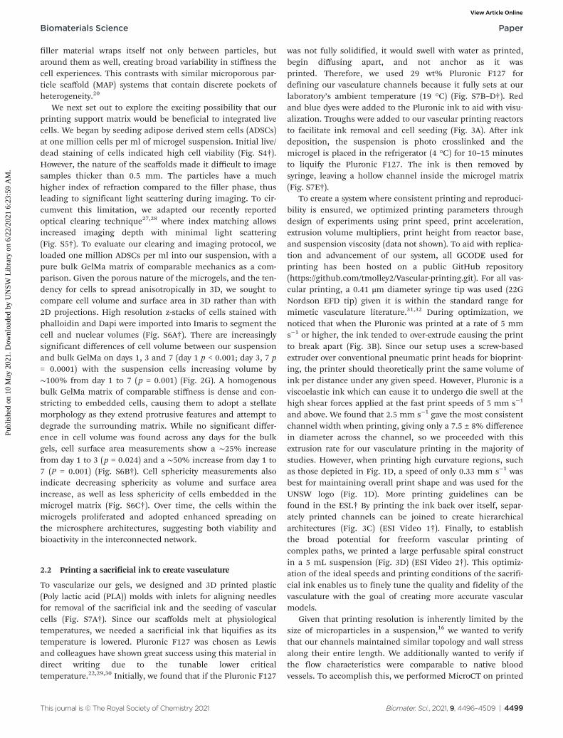
To create a system where consistent printing and reproduci-bility is ensured, we optimized printing parameters throughdesign of experiments using print speed, print acceleration,extrusion volume multipliers, print height from reactor base,and suspension viscosity (data not shown). To aid with replica-tion and advancement of our system, all GCODE used forprinting has been hosted on a public GitHub repository(https://github.com/tmolley2/Vascular-printing.git). For all vas-cular printing, a 0.41 μm diameter syringe tip was used (22GNordson EFD tip) given it is within the standard range formimetic vasculature literature.31,32 During optimization, wenoticed that when the Pluronic was printed at a rate of 5 mms−1 or higher, the ink tended to over-extrude causing the printto break apart (Fig. 3B). Since our setup uses a screw-basedextruder over conventional pneumatic print heads for bioprint-ing, the printer should theoretically print the same volume ofink per distance under any given speed. However, Pluronic is aviscoelastic ink which can cause it to undergo die swell at thehigh shear forces applied at the fast print speeds of 5 mm s−1
and above. We found that 2.5 mm s−1 gave the most consistentchannel width when printing, giving only a 7.5 ± 8% differencein diameter across the channel, so we proceeded with thisextrusion rate for our vasculature printing in the majority ofstudies. However, when printing high curvature regions, suchas those depicted in Fig. 1D, a speed of only 0.33 mm s−1 wasbest for maintaining overall print shape and was used for theUNSW logo (Fig. 1D). More printing guidelines can befound in the ESI.† By printing the ink back over itself, separ-ately printed channels can be joined to create hierarchicalarchitectures (Fig. 3C) (ESI Video 1†). Finally, to establishthe broad potential for freeform vascular printing ofcomplex paths, we printed a large perfusable spiral constructin a 5 mL suspension (Fig. 3D) (ESI Video 2†). This optimiz-ation of the ideal speeds and printing conditions of the sacrifi-cial ink enables us to finely tune the quality and fidelity of thevasculature with the goal of creating more accurate vascularmodels.
Given that printing resolution is inherently limited by thesize of microparticles in a suspension,16 we wanted to verifythat our channels maintained similar topology and wall stressalong their entire length. We additionally wanted to verify ifthe flow characteristics were comparable to native bloodvessels. To accomplish this, we performed MicroCT on printed
Biomaterials Science Paper
This journal is © The Royal Society of Chemistry 2021 Biomater. Sci., 2021, 9, 4496–4509 | 4499
Publ
ishe
d on
10
May
202
1. D
ownl
oade
d by
UN
SW L
ibra
ry o
n 6/
22/2
021
6:23
:59
AM
. View Article Online
single and bifurcated channels to create a 3D model of thevoid space. The microgel’s high protein and water contentallowed us to segment the microgel volume against air in thechannel rather than using contrasting agents (Fig. S8A andS9A†). Computational fluid dynamics (CFD) analysis was per-formed on the segmented channel volumes to measure wallshear stress along the channel lengths under theoretical flow(150 nL per second for straight channel, and 300 nL persecond for the bifurcation) (Fig. 3E). The variation of shearstress along the channel varies by ∼100% while also achievinga similar stress level within 12% to the theoretical/idealchannel design (0.72 dyn cm−2 for ideal, 0.64 dyn cm−2 for theprinted channel). Given that blood vessels experience a stressrange from 3–30 dyn cm−2, we find this variation to be accepta-ble.32 Fluid flow vectors also show the fluid path in bothchannel types (Fig. S8B and S9B†) with little deviation fromthe ideal channel conditions. Laminar flow is seen without thepresence of eddies in both channel types, with similar flowpatterns between the experimental and the theoretical channeldesigns (ESI Videos 3–6†). And a plot of the average flow vel-ocity magnitudes for ideal vs. printed channels gives only a∼25% variation. Taken together, these data indicate adequateflow characteristics.
2.3 Forming endothelial linings and printing cancer cells
Having established a method to fabricate hollow channelswithin the microgels, we next investigated the ability to inte-grate prototype vascular cells. Human umbilical vascular endo-thelial cells (HUVECs) were injected into the channels (107
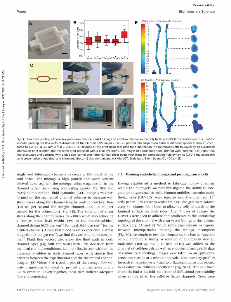
cells per mL) to create vascular linings. The gels were rotatedevery 30 minutes for 1 hour to allow the cells to attach to theluminal surface on both sides. After 5 days of culture theHUVECs were seen to adhere and proliferate to the undulatingtopology of the channel with clear vessel linings at the luminalsurface (Fig. 4A and B). While some gaps remain in regionsbetween microparticles making the linings incomplete(Fig. 4C), we sought to test their impact on the barrier functionof our endothelial lining. A solution of fluorescent dextranmolecules (100 µg mL−1, 40 kDa, FITC) was added to thechannel of cell-free gels as well as endothelialized gels (4 daysof culture post seeding). Images were taken on an epifluores-cence microscope at 5-minute intervals. Line intensity profilesfor each time point were fitted to a Gaussian curve and plottedto calculate the diffusion coefficient (Fig. S12†). The cell linedchannels had a 3.5-fold reduction of diffusional permeabilitywhen compared to the cell-free (bare) channels. Tests were
Fig. 3 Freeform printing of complex perfusable channels. (A) An image of a hollow channel in the Poly lactic acid (PLA) 3D printed reactors used forvascular printing. (B) Box plots of diameters of the Pluronic F127 ink (n = 28–35) printed into suspension baths at different speeds (5 mm s−1 com-pared to 1,2, 2.5, & 3.5 mm s−1; p = 0.0101). (C) Images of the print head tool path for a bifurcation in Pronterface (left) followed by an evacuatedbifurcation print (center) and the same print perfused with a blue dye (right). (D) Images of a four-loop spiral printed with Pluronic F127 (right) thatwas evacuated and perfused with a blue dye (center and right). (E) Wall shear stress heat maps for computation fluid dynamics (CFD) simulations runon representative single (top) and bifurcated (bottom) channels imaged via MicroCT. Scale bars: 3 mm (A and D), 400 μm (E).
Paper Biomaterials Science
4500 | Biomater. Sci., 2021, 9, 4496–4509 This journal is © The Royal Society of Chemistry 2021
Publ
ishe
d on
10
May
202
1. D
ownl
oade
d by
UN
SW L
ibra
ry o
n 6/
22/2
021
6:23
:59
AM
. View Article Online

attempted with 0% filler gels to measure if there is variation inendothelial lining tightness and barrier function, however itwas not possible to seed the endothelial cells as the gels weretoo porous. This caused cells to instantly flow throughout thegel when pipetted inside, as well as to be flushed out whenexternal media was applied on top of the gels.
At this stage, we can define blood vessel-like structureswithin a microgel matrix containing dispersed stromal cells.To investigate the propensity for including tumor-like struc-
tures, a B16 mouse melanoma tumor model was selected dueto its high invasiveness and characteristic black color frommelanin production which aids with visualization.33 A cellpellet fluidized with a 3 : 5 ratio of culture medium to cells waschosen as the cell ink for simplicity and a high cell density forin situ spheroid production. Parallel lines of printed tumortissue were first fabricated for viability assessment throughlive/dead imaging (Fig. S10†). The cell ink was readily extrudedand maintained its form while printing with little leakage into
Fig. 4 Vascular cell seeding and cancer cell printing. (A) Confocal plane of Huvec cells seeded along the walls of a printed channel after 5 days. (B)A cross section confocal image of the same gel to verify endothelial cells along the entire channel circumference. (C) A max intensity z-stack projec-tion (left, ImageJ) of the top half of a channel of endothelial cells after 5 days (Huvecs) along with a 3D projection image of the side view of thatchannel (right). (D) Epifluorescence images taken of 40 kDa FITC-Dextrans in cell-free (left images) and cell laden (right images) vascular channels atthe times of 0 (top) and 45 minutes (bottom). (E) Plot of calculated diffusion coefficients of 40 kDa Dextrans in cell laden and cell free vasculaturechannels (n = 3, p < 0.05). (F) Confocal image of the top (z-plane) of a U print of a fluidized cell pellet (B16F0). (G) Confocal images of printed tumorlines (B16F0) from a 27G needle (top) and 22G needle (bottom). (H) Plot of the measured average width of tumor line prints from 22G and 27Gneedles (n = 6, p < 0.001). Scale bars: 100 µm (A, B, C and G), 200 μm (D and F).
Biomaterials Science Paper
This journal is © The Royal Society of Chemistry 2021 Biomater. Sci., 2021, 9, 4496–4509 | 4501
Publ
ishe
d on
10
May
202
1. D
ownl
oade
d by
UN
SW L
ibra
ry o
n 6/
22/2
021
6:23
:59
AM
. View Article Online

the void space between microparticles (Fig. 4D). Cancer cellline thicknesses can be readily controlled by varying the dia-meter of the nozzle tip used (Fig. 4G and H). For further modu-larity, complex shapes can be printed as well as fused togethersuch as rings and thick discs of tumor (Fig. S11†).
2.4 Cancer cell migration through gels and towardsvasculature
To explore the role of the matrix on the tumor mimics growthand migration, human melanoma cells (WM266-4, 100 millioncells per ml) were printed into granular gels with 1%, 0.5%,and 0% filler. The volume fraction of particles was varied as
30%, 40% and 50% to maintain similar mechanical propertiesacross the gels (Fig. 2B). Two sets of gels were cultured for 2 or5 days, while one set was fixed immediately after printing tocreate a baseline of cell position prior to potential migration.No significant differences were found over the three timepoints for the 1% filler gels; however, the 0.5% and 0% fillergranular gels had roughly a ∼100% increase and ∼150%increase in tumor radius from days 0 to 2 and 5 (P < 0.0001),respectively (Fig. 5A). These trends were also verified whenprinted with a low cell density, demonstrating the initial cellpacking plays less of a role than matrix porosity (Fig. S13†). Ingels with 0.5% or less filler, there is little hydrogel impeding
Fig. 5 Printed cancer cell properties and triculture metastasis models. (A) Confocal images of WM266-4 cancer cells printed into granular gels with3 varied filler percentages at times points of 0, 2, and 5 days. Mimetic tumor radii were quantified at each time point and plot (n = 5–12, p < 0.0001).(B) A schematic of the tumor invasion model and phase contrast images of tumors printed close (i) and far (ii) from the vasculature. (C) ConfocalZ-projection of a triculture of ADSCs, Huvecs in a channel, and printed B16F0 cell pellets (top) along with a 3D projection (Zen blue, Zeiss) of thatsame gel (bottom). (D) Printed WM266-4 melanoma cells near straight (iv) and bifurcated (v) endothelial lined vasculatures. (i) Represents a zoom inof cell migration from tumor to vasculature while (ii and iii) represent two successive zoom ins of endothelial angiogenesis. Scale bars: 100 µm (D (i,ii and iii)), 200 μm (C), 400 μm (A), 500 μm (D (iv and v)).
Paper Biomaterials Science
4502 | Biomater. Sci., 2021, 9, 4496–4509 This journal is © The Royal Society of Chemistry 2021
Publ
ishe
d on
10
May
202
1. D
ownl
oade
d by
UN
SW L
ibra
ry o
n 6/
22/2
021
6:23
:59
AM
. View Article Online

the mass migration of cancer cells as they spread and prolifer-ate across and betwen particles. However, the gels with 1%filler have enough matrix for the tumor mimic to degrade thatthey maintain as a homogenous tumor mass unless givenexternal cues. Therefore, for all further studies, we used 1%filler gels to approximate a more physiologically relevanttumor model.
As a proof of concept to demonstrate a heterotypic tumormicroenvironment, we combined tumor printing with vascularprinting as a potential model of invasion. We began withprinting B16 melanoma aggregates at distances of either 1 mmor 3 mm from the vascular channel (Fig. 5B). Strikingly, beforetumor-mediated angiogenesis begins, the cancer cells within1 mm distance invaded the vasculature in under 4 days, whilethe tumor aggregates at 3 mm distance did not (Fig. 5B(i andii)). As paracrine signals play an important role in facilitatingcancer cell migration and invasion,34 we hypothesize thatthese tumor aggregates may be too far from the vascular liningto perceive endothelial cell-derived signals. As further demon-stration of modularity, a triculture model was created by per-forming both vascular printing and tumor printing simul-taneously in a microgel bath laden with adipose derivedstromal cells dispersed uniformly throughout the matrix. Here,all three cell types can be seen segregated into their desiredlocations (Fig. 5C). After five days, tumor cells labelled withCellTracker can be seen intravasating from the tumor massinto the vasculature (Fig. 5C, yellow arrows; Fig. S14†). Toverify the phenomenon of directed migration of tumor cells tothe vasculature, we extended the tri-culture model to thehuman WM266-4 melanoma cells (Fig. 5D(i–iv)). Cancer cellswere deposited at distances of 0.5, 0.75 and 1.0 mm from thechannel center (right to left, Fig. 5D(iv)). A mass migration oftumor cells can be seen in the tumor printed closest to thechannel (Fig. 5D(i)) which then invaded throughout the rest ofthe channel during the 5 days of culture. In contrast, thetumor furthest away induced directional neovascularizationfrom the channel suggesting bi-directional signaling betweenthe two cell types (Fig. 5D(ii and iii)). As a demonstration ofversatility, melanoma cells were printed within a hierarchicalvasculature (Right and left tumors: distance of 0.5 mm fromthe bifurcations; Center tumor: 1 mm from the daughtervessels) where extensive migration of tumor cells can be seenat the bifurcations (Fig. 5D(v)).
3 Discussion
The advent of freeform bioprinting has led to a rapid develop-ment in tools to reconstruct tissue-like structures for modeldevelopment and tissue engineering applications.13,15 Recentwork by Feinberg and colleagues and Angelini and colleagueshas provided new avenues for bioprinting that obviated theneed for overly viscous inks through the use of yield stressfluid support baths, enabling 3D printing of intricate struc-tures with broad flexibility in materials selection.14,16,19 Thetwo main suspension bath materials used with this printing
technique include Carbopol and gelatin microspheres. Whilethese suspensions have excellent yield stress fluid character-istics that allow for ease of printing, they are typically removedpost print.
Rather than using the microgel suspension as a sacrificialprinting medium, here we recognized the jammed suspensionas a spatially addressable extracellular matrix, in which cellularactivity may be dictated by the properties of the suspension.The Segura group and others have explored these types of gran-ular gels as a cell seeded scaffold to capture the benefits theporous nature of the scaffolds provides,35–37 thereby demon-strating the potential for cells to be integrated with microgels.Recently, Patrício et al. showed freeform printing of a sacrifi-cial ink into a alginate microgel bath.38 And in an interestingtwist to the composition of the yield stress fluid for printing,Lewis and colleagues demonstrated freeform vascular printingin a suspension of pure cell organoids.24 In contrast, whilethese studies focus on the goal of vascularizing large tissueconstructs for regenerative medicine, as does an overwhelmingmajority of current suspension bath printing studies, our aimwas to translate the unique benefits afforded by this spatialcontrol towards establishing in vitro models with potential forhigh throughput assays.39 We leveraged the benefits associatedwith the microporous nature of the granular bath to create acell-laden tunable bioactive matrix, where multiple cell typescan be spatially integrated. By coupling a photocrosslinkablefiller polymer between the individual microgels, we can stabil-ize the gels post print enabling removal of a sacrificial ink,unveiling complex channels within the cell-laden matrix.These channels were further modified with endothelial cellstowards well defined prototype vessels.
A major advantage with printing in granular media is theability to print very low viscosity inks without the need for anink drop printer. Alsberg and colleagues demonstrated this byprinting pure pellets of stem cells into their alginate particlebaths.17 In a similar way, we printed tumor aggregates ofvaried shapes and sizes. Importantly, our approach allows cel-lular aggregates to be spatially defined in the presence of uni-formly dispersed cells and interspersed vascular channels. Wedemonstrated this by printing microtumors of melanoma cellsat varying distances from prototype vessels with evidence fordistance-invasion relationships. Microfluidic systems withadjacent chambers and counterflow arrangements have servedas complex heterotypic models to monitor signaling betweenmultiple cell types.40 However, these platforms invariablyinvolve cells adherent to 2D surfaces which disallows variationin the biochemical and biophysical properties of the micro-environment. Our printing system allows similar associationsto be fabricated and monitored in a single bioreactor, in a 3Dcontext with tailorable chemistry and mechanics, thereby pro-viding a more biomimetic environment to study cellularprocesses.
A growing variety of materials have now been used as granu-lar gels for supporting freeform 3D printing, including, butnot limited to, pure gelatin, alginate, hyaluronic acid, andCarbopol.13,15,38,41 While these support gels enable the depo-
Biomaterials Science Paper
This journal is © The Royal Society of Chemistry 2021 Biomater. Sci., 2021, 9, 4496–4509 | 4503
Publ
ishe
d on
10
May
202
1. D
ownl
oade
d by
UN
SW L
ibra
ry o
n 6/
22/2
021
6:23
:59
AM
. View Article Online

sition of compatible hydrogel inks, there are a few key criteriarequired for the incorporation of vasculature and cells. One,the gel needs binding domains for the cells; two, the gel mustbe stabilized post print; and three, the support gel must have amesh size small enough to enable endothelial cells to bind toeach other and form tight linings. In our case, we found thatwithout the filler polymer, our mesh size was so large thatcells immediately leaked throughout the entirety of the gel.Furthermore, when adding culture medium to surround thegel, the porosity allowed the media to quickly penetrate thenetwork and flush the cells out before they had a chance toadhere to the channel walls. This limitation can be avoided bymaking granular gels with microparticles smaller than thecells used. However, jammed microgels of small size tend toyield poor cell viability, growth, and fucntion.19,42 By combin-ing our large microspheres with a dilute filler around them, wemaintain the ability to create endothelial linings while stillretaining optimal cell conditions in the surrounding gel. Thefiller polymer also helps prevent unwanted migration from theprinted cancer cells. With a sufficiently high enoughfiller content, the cells maintain more cell–cell connections,staying more as a tumor aggregate, rather than dissociatingand spreading throughout the material. Once given someexternal cue, in our case from endothelial cells, the tumor cellscan preferentially dissociate towards the signal, providingscope for the development of tumor models where more soph-isticated questions in the biology of metastasis may beinvestigated.
4 Conclusion
In conclusion, we have demonstrated a bioprinting approachbased on a suspension of live cells and crosslinkable granularmedia, where freeform printing of vascular channels and cellu-lar aggregates is accomplished in a single chamber. Key to thisapproach is the use of photo-crosslinkable biopolymers tomake up the microgels, a filler phase to “stitch” microgelstogether, and a thermoresponsive Pluronic ink as a sacrificialmaterial to make up the channel. Inspired by the tumor micro-environment, we demonstrate the versatility of this system byintegrating prototype tumors and vasculature amidst a matrixof stromal cells. In this way complex processes like tumorintravasation and extravasation, and accompanying roles ofstroma-cancer cell interaction, can be readily modelled.Coupled with the ability to simultaneously deposit additionalcells with a high degree of spatial control, virtually anynumber of cell types may be integrated. This new 3D coculturemethod may provide a means to investigate not only cancerand disease modeling but understanding the role of the extra-cellular matrix on other cellular processes including tissuemorphogenesis in development and disease. Moreover, thehigh throughput nature of 3D printing combined with thismodular approach will allow for combinatorial drug studies tobe performed in well-defined models.
5 Materials and methods5.1 GelMa synthesis
GelMa was synthesized as previously described.27,43 Briefly,gelatin from porcine skin, Type A (Bloom strength 300, Sigma-Aldrich) was dissolved at 10% (w/v) in 1× phosphate bufferedsaline (PBS, pH 7.4) under stirring at 50 °C. 5% (v/w)methacrylic anhydride (Sigma-Aldrich) was added and themixture stirred for 90 minutes. The solution was diluted two-fold with 1× PBS and centrifuged (3000 rcf, 3 minutes) toremove unreacted methacrylic anhydride particulates.Following this, it was transferred into 14 kDa cutoff cellulosedialysis tubes and dialyzed at 40 °C for 5–7 days against de-ionized water. The dialyzed solution was lyophilized for 5–7days and the resulting powder stored was stored at −20 °C.
5.2 GelMa microparticle synthesis
The GelMa microparticles were prepared using a modifiedwater in oil emulsion method.44 The lyophilized GelMa washydrated to a 10% (w/v) volume solution in 1× PBS at 40 °C.The solution was added dropwise through a 0.45 μm sterilefilter into a continuously stirring bath of oil (Canola,Sunflower, Olive) (Community Co., IGA Australia; Bertolli) at40 °C and allowed to equilibrate for 10 minutes. The bath wascooled to 10 °C for 30 minutes prior to adding acetone (22 mLmL−1 GelMa) to dehydrate the microparticles. The particleswere then allowed to settle to the bottom of the vessel, washedthoroughly with acetone, and sonicated to break up aggre-gates. Unbroken aggregates were removed by filtration. The de-hydrated microparticles were stored in acetone until use. Forsize characterization, particles were rehydrated in DI water forone day before taking images on a phase contrast microscope.100 particles were imaged, and their diameters were calculatedusing ImageJ.
To prepare the microparticles for printing, acetone wasremoved by evaporation. The microparticles were hydrated forat least 24 hours in a 1% (w/v) solution of GelMa and 0.05 wt%Lithium phenyl-2,4,6-trimethylbenzoylphosphinate (LAPSigma-Aldrich, 900889) in either PBS, or appropriate cellculture medium, to achieve a packing fraction of 30% and afinal concentration of 1 wt% GelMa in the filler phase as thesewere determined to be optimal conditions for printing.
5.3 Swelling study
A 10 wt% solution of pure GelMa dissolved in 1× PBS waswarmed in an incubator at 37 °C until fully melted. The gelsolution (80 µL) was subsequently added to 6 × 6 × 2.5 mmplastic PLA molds and left at room temp to physically cross-link. Once crosslinked, the gels were weighed and placed into15 mL falcon tubes where they were covered with Acetone(10 mL, Chem-supply) and left to shake for 24 hours. Theacetone was then decanted, and the gels were air dried for24 hours to remove all remaining acetone. The dried gels werethen weighed before placing into tubes filled with DI water atroom temperature. At each time point, the gels were takenfrom the tube and the surface water was removed with a
Paper Biomaterials Science
4504 | Biomater. Sci., 2021, 9, 4496–4509 This journal is © The Royal Society of Chemistry 2021
Publ
ishe
d on
10
May
202
1. D
ownl
oade
d by
UN
SW L
ibra
ry o
n 6/
22/2
021
6:23
:59
AM
. View Article Online

Kimwipe prior to weighing. The swelling ratio was calculatedusing the following where W is the weight:
Swell ratio ¼ Wswelled �Wdried
Wdried
5.4 Rheology
All rheological measurements were performed on an AntonPaar MCR 302 Rheometer with a parallel plate geometry(25 mm Disk, 1 mm measuring distance, 600 µL of suspensionbath or Pluronic gel). Oscillatory measurements were per-formed with 0.02% strain and a 1 Hz frequency for the dur-ation of gelation at 20 °C. For in situ UV crosslinking for theGelMa baths, a UV light (with 395 nm UV light at 40 mW cm−2
for 60 seconds) was placed underneath to illuminate thesample through the quartz crystal stage. Shear rate sweepswere performed with a 1 Hz frequency from a 0.01 to 10 shearrate (1 s−1) at a log ramp scale over 4 minutes. Temperaturestability studies for GelMa baths were run with a temperatureramp from 20 °C to 37 °C. For the melted samples test, thegels were first placed in an incubator at 37 °C for one hourbefore placing on the rheometer and cooling down to 20 °Cbefore running the test. Strain sweep test were performed witha log ramp up rate from 0.02% shear strain up to 200% at 1 Hzfrequency over 8 minutes. For the Pluronic temperature sweep,the samples were cooled down in the fridge to 4 °C beforeplacing them on the rheometer at 1 °C. The temperature wasramped up from 1 °C to 37 °C at a rate of 1 °C per minute witha 0.02% shear strain at 1 Hz frequency. The frequency sweepwas run with a log ramp up rate from 0.01 to 100 Hz with a0.02% strain.
5.5 Atomic force microscopy (AFM)
Suspensions of 30Vf GelMa particles with filler were cross-linked in 6 × 6 × 1 mm plastic molds glued down to glass cov-erslips. Shorter molds were used to limit light diffraction forthe camera on the AFM’s microscope. The samples were fixedto the bottom of fluorodishes (Coherent, FD35) with 2-partrubber cement. The samples were then submerged in wateruntil ready. All data was acquired with the JPK NanoWizard4Bio-AFM with a spherical probe (2 µm diameter Borosilicateunmodified probe, Novascan). The tip spring constant wascalibrated on glass in water prior to the experiment. Usingcontact-force microcopy mode, 36 force curves (6 µm approachat 0.5 µm per second) were taken per 10 × 10 µm regions indifferent locations of the gel. A stitched optical image wastaken to find particles and filler spaces between. The curveswere loaded in the JPK Data Processing software to calculatethe elastic modulus at each region. The following analysissteps were performed:
1. Gaussian smoothing of the curve with a smoothingwidth of 3.00.
2. Baseline subtraction with tilt using the last 40% of thecurve along the x-axis.
3. Automatic contact point adjustment.
4. Vertical tip position calibration using the unsmoothedheight.
5. An elasticity fit using the Hertz/Sneddon model with aspherical tip shape with a 1 μm tip radius and 0.50 Poissonratio.
5.6 Cell culture and seeding in bulk suspensions
The B16F0 (ATCC) cells were cultured with high glucoseDulbecco’s Modified Eagle Medium (DMEM) supplementedwith 10% FBS and 1% Penicillin/Streptomycin. Adiposederived stem cells (ADSCs, PSC-500-011 ATCC) were cultured inlow glucose DMEM supplemented with 10% FBS and 1%Penicillin/Streptomycin. GFP-WM266-4 cells with were cul-tured in Minimum Essential Medium Eagle (MEME) with 10%FBS, 1% Glutamax, and 1% Penicillin/Streptomycin. HUVECs(Lonza C2519A) were cultured with the Endothelial CellGrowth Medium-2 BulletKit (Lonza CC-3162) All cultures weremaintained at 37 °C, 5% CO2 and used between passages2–13. For ADSCs seeding in the hydrogel matrices, the cellswere detached with trypsin, counted, centrifuged down, andresuspended to 2 × 10⁷ cells per mL. The cells were then addedin a 1 : 20 volume ratio to either a solution of 10 wt% GelMa at37 °C or a prehydrated bath of GelMa particles at room temp-erature for a final concentration of one million cells per mL. Inorder to intermix the cells with the granular gels, the solutionswere pipetted up and down extensively before centrifugation at300 rcf for 3 minutes to remove air bubbles that had beenadded. These solutions were subsequently supplemented to0.05 wt% LAP with a 2.5 wt% stock. 80 µL of each gel solutionwas then added to plastic printed molds (6 × 6 × 2.5 mm)where they were crosslinked under a 395 nm light torch (eBay;100 LED 395 nm UV Ultraviolet Flashlight Blacklight Torch) at40 mW cm−2 for 60 seconds. The cells were added to a 24 wellplate with 1 ml of media. Media was changed after one day fol-lowed by every other day. The gels were cultured for 1–7 daysbefore fixation with PFA.
5.7 Cell viability analysis
For ADSCs, 1 million cells per mL were loaded into both the10 wt% GelMa solution and 30-volume fraction microgel bath,each with 0.05 wt% LAP. Next, 80 µL of gel was placed into a 6× 6 × 2.5 mm plastic mold where the gels were crosslinked for1 minute. For the B16F0s, the cell ink was prepped as specifiedelsewhere. Three lines (22G needle, 5 mm long) of cancer cellswere printed into each gel prior to crosslinking. All cell loadedgels were placed into a 24 well plate and cultured for the speci-fied time. Media changes were made on days 1, 3, and 5. Forthe staining, the media was removed and the gels were washedonce with PBS prior to the addition of 500 µL of 1× PBS withCalcein AM (2 µM) and Ethidium Homodimer-1(4 µM)(Invitrogen, L3224). After 45 minutes of incubating the stains,the gels were rinsed with PBS and washed again with PBS after10 minutes before imaging on a Zeiss LSM 800 Confocalmicroscope.
Biomaterials Science Paper
This journal is © The Royal Society of Chemistry 2021 Biomater. Sci., 2021, 9, 4496–4509 | 4505
Publ
ishe
d on
10
May
202
1. D
ownl
oade
d by
UN
SW L
ibra
ry o
n 6/
22/2
021
6:23
:59
AM
. View Article Online

5.8 Immunofluorescence staining and tissue clearing
Clearing solutions were prepared as done previously withminor modifications (Molley 2020, susaki 2014). Briefly, Cubicsolution 1 was prepared by mixing 25 wt% urea (SigmaAldrich., 583051), 25 wt% N,N,N′,N′-tetrakis(2-hydroxypropyl)ethylenediamine (Sigma Aldrich, 585714), and 5 wt% TritonX-100 (Sigma Aldrich, 562380) into DI water at 50 °C until fullydissolved. Cubic solution 2 was prepared by mixing 50 wt%sucrose (Sigma Aldrich, 584173), 25 wt% urea, 10 wt% tri-ethanolamine (Sigma Aldrich, 90278–100 mL) with DI water at55 °C until also fully dissolved. Microgel suspensions werefixed using a 4 wt% paraformaldehyde (Chem-Supply) for 1–4days at room temperature to ensure fully penetration of PFAinto thick constructs. The gels were then rinsed with PBS fol-lowed by 3 PBS washes at 2–4-hour intervals. The Hoechst(1 : 1000) and 488-Phalloidin (1 : 200) staining was then per-formed overnight at room temperature. The gels were washedwith PBS three final times before the addition of the Cubic 2clearing solution for 2–5 days. All confocal imaging was per-formed with a Zeiss LSM 800. A 10× objective with a 2.5 mmworking distance was used to see deeper into the samples.Samples were coated with clearing 2 solution throughout theduration for the imaging to prevent drying.
5.9 Cell volume segmentation analysis
For cell volume analysis, one million ADSCs were loaded intomicrogel suspensions and bulk hydrogels before crosslinkingfor 60 seconds. At the desired time points, the cells were fixedwith 4% PFA for 24 hours before staining (Hoechst, 405;Phalloidin, 488) and cleared as mentioned above. Confocalz-stacks (20× objective, 109 slices over 50 µm) were taken ofrepresentative regions in each gel. The images were importedin Imaris 9.5.1 for analysis. Cell segmentations were createdusing the Cell module with the phalloidin stain as the cellbody and Hoechst for the cell nuclei. For each image was ana-lyzed using identical thresholding values per gel with eachindependent nucleus as a seed for the cells.
5.10 Plastic reactor mold fabrication
All plastic reactor molds were 3D printed with a Lulzbot Mini2plastic 3D printer with a 0.25 mm nozzle end. For cell experi-ments, molds are fixed to an 18 mm diameter glass coverslipwith cyanoacrylate glue. The molds are then quickly soakedwith 80 vol% ethanol and dried out inside of a biosafetycabinet prior to use. For non-cell experiments, the reactors arepressed into stretched parafilm before addition of the microgelsuspension and subsequent crosslinking. STL files for themolds can be found here: https://www.thingiverse.com/tmolley/collections/freeform-vascular-printing-designs.
5.11 Pluronic ink preparation
To create the sacrificial inks, Pluronic F127 (Sigma, P2443-250G) was first weighed out into 50 mL flacon tubes. Cold DIwater (4 °C) was then added to the Pluronic powder for theappropriate weight percentage. The mixture was mechanically
agitated before placing into a fridge at 4 °C overnight to fullydissolve the ink. The ink was then stored at 4 °C until furtheruse.
5.12 MicroCT and volume segmentation
MicroCT scan was performed with the U-CT (MILabs, Utrech),with 50 kVp X-ray tube voltage, 0.21 mA tube current, 75 msper frame, 360° angle, and 0.25° projections. Images werereconstructed with MILabs Recon 10.16 at 20 µm voxel sizeand vessels segmented using Imalytics Preclinical 2.1 (Gremse-IT GmbH, Germany).
5.13 CFD and analysis
Computational fluid dynamics (CFD) analysis was run with theAutodesk CFD 2019® software. The segmented STL meshesexported from Imalytics Preclinical 2.1 were imported inAutodesk 360 Fusion® to reduce the mesh network down to<10 000 polygons for smoother modeling. Theoretical modeldesigns were created in Autodesk Inventor CAD to representthe shape the gcode was supposed to create. The meshvolumes were the loaded in the CFD software and the follow-ing assumptions were made:
1. Volume is specified as water.2. End boundary condition set to 0 Pa pressure.3. Automatic meshing.4. 0 initial conditions.5. Fluid is incompressible.6. Flow was set to a kappa-epsilon turbulent flow model
with a turbulent : lamilar flow ratio of 100 : 1.7. ADV 5 modified Petrov–Galerkin advection.8. 100 iterations were performed with a steady state solu-
tion mode.9. Flow rate defined as 150 nL s−1 for the straight
channel and 300 nL s−1 for the bifurcation.10. The bifurcation had flow originating from the single
channel end.Videos of flow traces were recorded and exported from the
software.
5.14 Printing (vasculature, tumors, co-culture cell baths)
5.14.1 Printing vasculature. A Lulzbot mini2 retrofittedwith a screw extrusion syringe head (Replistruder head 2,Feinberg lab) was placed into a Biosafety cabinet. For Pluronicprinting, the 29 wt% Pluronic F127 solution was cooled downin a fridge (4 °C), then pulled into an airtight glass syringe(Hamilton® 1002LTN syringe) and inverted to remove airbubbles. The syringe was warmed to room temperature to gelthe Pluronic F127 before loading into the printer. A 22GNordson EFD needle tip was added to the syringe and a smallamount of Pluronic was extruded out to prime the needle tip.The print needle was then orientated over and aligned with theinlet and the suspension was added to the mold until thesurface of the liquid was flush with the top of the mold. Thedesired print code was run, and the needle was gently cleanedwith a Kimwipe prior to the next print. The suspension wasthen photocrosslinked for 1 minute, placed into a 12 well
Paper Biomaterials Science
4506 | Biomater. Sci., 2021, 9, 4496–4509 This journal is © The Royal Society of Chemistry 2021
Publ
ishe
d on
10
May
202
1. D
ownl
oade
d by
UN
SW L
ibra
ry o
n 6/
22/2
021
6:23
:59
AM
. View Article Online

plate, parafilmed, and put in a fridge for 15 minutes to liquifythe Pluronic F127. For print fidelity measurements, the inkwas removed and Phase contrast images of the air inside thechannel were taken. Analysis was performed via ImageJ along6 diameters for each line to determine the lines averagethickness.
5.14.2 Direct printing of cells. The desired cells weretreated with trypsin, centrifuged, washed, and then pelleted.The cell pellets were lightly fluidized with media in a 5 : 3–5 : 2ratio of cells to media to break up aggregates. Care was takento limit the introduction of air bubbles during this stage. Thepellet was then pulled into a 1 mL syringe (Livingston), andthe syringe was loaded directly into a 3D printed fitting on thebioprinter. The desired syringe needle was then primed withcell solution and printed into molds filled with a microgelsuspension.
5.14.3 Dual cell and vascular printing. Each part of themultistage printing process was performed as mention abovewith some modifications. Importantly, cell printing precededvascular printing as the Pluronic ink begins to diffuse into thesurrounding suspension if not crosslinked fast enough leadingto poor channel resolution. In addition, after cell printing, themolds are placed into a covered, sterile Petri dish to enableeasy access while limiting overhead airflow that can dry out orcontaminate the microgel suspension.
5.14.4 Incorporating cells into suspensions. When incor-porating cells into the support suspensions, the microparticleswere first hydrated with the appropriate culture medium. Thecells were treated with trypsin, centrifuged to a pellet, thenresuspended to a 50× cells mL concentration compared to thefinal volume. The high concentration cell solution was gentlymixed into the hydrated microparticles before adding to themolds. Printing was then conducted as mentioned prior.
5.15 Loading vascular cells in printed vasculature andsubsequent co-culture
The microgels were placed into a fridge for 15 minutes toallow the Pluronic F127 to transition into a liquid state. It wasthen removed via holes at either end of the mold, leavingbehind a hollow channel. Endothelial cells (HUVECs at10–20 million cells per mL) were loaded into a 1 mL syringeand injected into the channel through the same holes at eitherend of the mold. The microgel was inverted and placed in a12-well plate, then placed in the incubator for 30 minutes. Thevessels were then flipped back upright and incubated foranother 30 minutes before adding the cell media. The con-struct was cultured at 37 °C for 4–7 days.
5.16 Fidelity of tumor prints
For tumor line prints, a sacrificial print was first made abovethe microgel suspension to prime the needle tip. Onceprinted, the microgels were immediately fixed with 4% PFA.After fixation and washing of the fixed microgels, they wereadded to a 5 wt% solution of Hydrogen Peroxide (SigmaAldrich, 487568) at room temperature for 24 hours to bleachthe melanin and aid in confocal imaging. The samples were
then stained with Hoechst and Phalloidin and z-stack tilescans of the gels were taken. Analysis was performed inImageJ. First, the z-stacks were projected into one slice withusing the maximum brightness. The images were then thre-sholded in the phalloidin channel to outline the lines, fol-lowed by 6 length measurements taken across the length ofthe tumor lines.
5.17 Endothelial barrier function
Printed channels were formed in 1% filler granular gels andeither loaded with endothelial cells or 1× PBS. After 4 days, thegel channels, with live cells, were loaded with 40 kDa FITC-dextran (100 μg mL−1, Sigma FD40-100MG) before placing on awide-field fluorescent microscope. Images were taken of thechannels every 5 minutes for 45 minutes and imported intoMATLAB for analysis. We assume that the fluorescent intensityof the FITC dextran is directly proportional to the dye concen-tration. And we also assume that the dye undergoes 1D fickiandiffusion. Using this, we fit middle profile of each image isfitting to a Gaussian function for each time point to obtain thespatial peak variance fitting parameter σ2. By using theEinstein–Smoluchowski relation:
σ 2 ¼ 2Dt
where σ2 is the spatial peak variance, D is the diffusion con-stant, and t is time, we can plot σ2 as a function of time todetermine the diffusion constant.
5.18 NMR for GelMa methacrylation characterization
The degree of functionalization (DOF) was quantified using a1H NMR spectrometer (Bruker Avance III 400 MHz) by referen-cing 1H NMR chemical shifts to the residual solvent peak at4.80 ppm in D2O. Briefly, 10 mg of GelMA was dissolved in1 mL of D2O at 37 °C. 700 µL was put into an NMR tube forthe acquisition of the NMR data. NMR spectra were analyzedusing MestReNova (Mestrelab Research) by Dr Julio Serrano(University of Illinois at Urbana-Champaign), using the chemi-cal shift in the aromatic region as integral reference. Degree offunctionalization of 96 and 98% can be seen in Fig. S15.† 1HNMR (400 MHz, D2O): δ 7.24 (m), 5.65 (m), 5.40 (m).
5.19 Statistical analysis
The whiskers in the box plots are standard deviation(s.d.) unless otherwise specified. Analyses of tumor migrationradii were calculated in imageJ. Statistical significance wasdetermined using a one-way ANOVA with Tukey’s PostHoc HSD analysis. Differences were considered significantwhen P < 0.05.
Conflicts of interest
There are no conflicts of interest to declare.
Biomaterials Science Paper
This journal is © The Royal Society of Chemistry 2021 Biomater. Sci., 2021, 9, 4496–4509 | 4507
Publ
ishe
d on
10
May
202
1. D
ownl
oade
d by
UN
SW L
ibra
ry o
n 6/
22/2
021
6:23
:59
AM
. View Article Online

Acknowledgements
This work was supported through funding from the NationalHealth and Medical Research Council Grant # APP1185021and the National Cancer Institute of the National Institutes ofHealth Grant # 1R01CA251443. This material is also basedupon work supported by the National Science FoundationGraduate Research Fellowship Program and the NationalScience Foundation Graduate Research OpportunitiesWorldwide program under Grant No. DGE-1144245 (A. S. T.).We acknowledge the help and support of staff at theBiomedical Imaging Facility and the Biological SpecimenPreparation Laboratory of the UNSW Mark WainwrightAnalytical Centre.
References
1 A. Malandrino, R. D. Kamm and E. Moeendarbary, ACSBiomater. Sci. Eng., 2018, 4, 294.
2 M. Nicolau, A. J. Levine and G. Carlsson, Proc. Natl. Acad.Sci. U. S. A., 2011, 108, 7265.
3 C. E. Tschirhart, A. Nagpurkar and C. M. Whyne,J. Biomech., 2004, 37, 653.
4 J. M. Bailey, A. M. Mohr and M. A. Hollingsworth,Oncogene, 2009, 28, 3513.
5 M. C. Kwon, N. Proost, J. Y. Song, K. D. Sutherland,J. Zevenhoven and A. Berns, Genes Dev., 2015, 29, 1587.
6 Y. Chen, X. Gou, D. K. Kong, X. Wang, J. Wang, Z. Chen,C. Huang and J. Zhou, Oncotarget, 2015, 6, 32575.
7 I. J. Fidler, S. Yano, R. D. Zhang, T. Fujimaki andC. D. Bucana, The seed and soil hypothesis: Vascularisationand brain metastases, Lancet Publishing Group, 2002.
8 S. Kenig, M. B. D. Alonso, M. M. Mueller and T. T. Lah,Cancer Lett., 2010, 289, 53.
9 S. Rao, R. Sengupta, E. J. Choe, B. M. Woerner, E. Jackson,T. Sun, J. Leonard, D. Piwnica-Worms and J. B. Rubin, PLoSOne, 2012, 7, e33005.
10 M. Upreti, A. Jamshidi-Parsian, N. A. Koonce, J. S. Webber,S. K. Sharma, A. A. A. Asea, M. J. Mader and R. J. Griffin,Transl. Oncol., 2011, 4, 365.
11 C. Wang, J. Li, S. Sinha, A. Peterson, G. A. Grant andF. Yang, Biomaterials, 2019, 202, 35.
12 Y. Kam, K. A. Rejniak and A. R. A. Anderson, J. Cell.Physiol., 2012, 227, 431.
13 T. Bhattacharjee, S. M. Zehnder, K. G. Rowe, S. Jain,R. M. Nixon, W. G. Sawyer and T. E. Angelini, Sci. Adv.,2015, 1, e1500655.
14 C. D. Morley, J. Tordoff, C. S. O’Bryan, R. Weiss andT. E. Angelini, Soft Matter, 2020, 16, 6572.
15 T. J. Hinton, Q. Jallerat, R. N. Palchesko, J. H. Park,M. S. Grodzicki, H.-J. Shue, M. H. Ramadan, A. R. Hudsonand A. W. Feinberg, Sci. Adv., 2015, 1, e1500758.
16 A. Lee, A. R. Hudson, D. J. Shiwarski, J. W. Tashman,T. J. Hinton, S. Yerneni, J. M. Bliley, P. G. Campbell andA. W. Feinberg, Science, 2019, 365, 482.
17 O. Jeon, Y. B. Lee, H. Jeong, S. J. Lee, D. Wells andE. Alsberg, Mater. Horiz., 2019, 6, 1625–1631.
18 N. Noor, A. Shapira, R. Edri, I. Gal, L. Wertheim andT. Dvir, Adv. Sci., 2019, 6, 1900344.
19 S. Romanazzo, T. G. Molley, S. Nemec, K. Lin, R. Sheikh,J. J. Gooding, B. Wan, Q. Li, K. A. Kilian and I. Roohani,Adv. Funct. Mater., 2021, 2008216.
20 A. C. Daly, L. Riley, T. Segura and J. A. Burdick, Hydrogelmicroparticles for biomedical applications, Nature Research,2020.
21 W. Wu, A. Deconinck and J. A. Lewis, Adv. Mater., 2011, 23,H178.
22 D. B. Kolesky, K. A. Homan, M. A. Skylar-Scott andJ. A. Lewis, Proc. Natl. Acad. Sci. U. S. A., 2016, 113, 3179.
23 K. Kobayashi, Y. Ichihara, N. Sato, N. Umeda, L. Fields,M. Fukumitsu, Y. Tago, T. Ito, S. Kainuma, M. Podaru,F. Lewis-McDougall, K. Yamahara, R. Uppal and K. Suzuki,Biomaterials.
24 M. A. Skylar-Scott, S. G. M. Uzel, L. L. Nam, J. H. Ahrens,R. L. Truby, S. Damaraju and J. A. Lewis, Sci. Adv., 2019, 5,eaaw2459.
25 S. A. Wickström and C. M. Niessen, Cell adhesion and mech-anics as drivers of tissue organization and differentiation:local cues for large scale organization, Elsevier Ltd, 2018.
26 E. Potier, J. Noailly and K. Ito, Directing bone marrow-derived stromal cell function with mechanics, Elsevier, 2010.
27 E. A. Susaki, K. Tainaka, D. Perrin, H. Yukinaga, A. Kunoand H. R. Ueda, Nat. Protoc., 2015, 10, 1709.
28 T. G. Molley, X. Wang, T. Hung, P. B. Jayathilaka, J.-L. Yangand K. A. Kilian, Adv. Biosyst., 2020, 2000056.
29 N. Y. C. Lin, K. A. Homan, S. S. Robinson, D. B. Kolesky,N. Duarte, A. Moisan and J. A. Lewis, Proc. Natl. Acad.Sci. U. S. A., 2019, 201815208.
30 D. B. Kolesky, R. L. Truby, A. S. Gladman, T. A. Busbee,K. A. Homan and J. A. Lewis, Adv. Mater., 2014, 26, 3124.
31 J. L. Rein, S. Heja, D. Flores, R. Carrisoza-Gaytán,N. Y. C. Lin, K. A. Homan, J. A. Lewis, L. M. Satlin andL. Nyc, Am. J. Physiol.: Cell Physiol., 2020, 319, 136.
32 W. J. Polacheck, M. L. Kutys, J. Yang, J. Eyckmans, Y. Wu,H. Vasavada, K. K. Hirschi and C. S. Chen, Nature, 2017,552, 258.
33 J. Lee, A. A. Abdeen, K. L. Wycislo, T. M. Fan andK. A. Kilian, Nat. Mater., 2016, 15, 856.
34 Y. H. Wang, Y. Y. Dong, W. M. Wang, X. Y. Xie, Z. M. Wang,R. X. Chen, J. Chen, D. M. Gao, J. F. Cui and Z. G. Ren,J. Exp. Clin. Cancer Res., 2013, 32, 1.
35 N. F. Truong, E. Kurt, N. Tahmizyan, S. C. Lesher-Pérez,M. Chen, N. J. Darling, W. Xi and T. Segura, Acta Biomater.,2019, 94, 160.
36 D. R. Griffin, W. M. Weaver, P. O. Scumpia, D. D. Carlo andT. Segura, Nat. Mater., 2015, 14, 737.
37 A. Kodali, T. C. Lim, D. T. Leong and Y. W. Tong, Macromol.Biosci., 2014, 14, 1458.
38 S. G. Patrício, L. R. Sousa, T. R. Correia, V. M. Gaspar,L. S. Pires, J. L. Luís, J. M. Oliveira and J. F. Mano,Biofabrication.
Paper Biomaterials Science
4508 | Biomater. Sci., 2021, 9, 4496–4509 This journal is © The Royal Society of Chemistry 2021
Publ
ishe
d on
10
May
202
1. D
ownl
oade
d by
UN
SW L
ibra
ry o
n 6/
22/2
021
6:23
:59
AM
. View Article Online

39 K. H. Song, C. B. Highley, A. Rouff and J. A. Burdick, Adv.Funct. Mater., 2018, 1801331.
40 M. Rothbauer, H. Zirath and P. Ertl, Recent advances inmicrofluidic technologies for cell-to-cell interaction studies,Royal Society of Chemistry, 2018.
41 K. H. Song, C. B. Highley, A. Rouff and J. A. Burdick, Adv.Funct. Mater., 2018, 28, 1801331.
42 K. Hayashi and Y. Tabata, Acta Biomater., 2011, 7, 2797.43 D. Loessner, C. Meinert, E. Kaemmerer, L. C. Martine,
K. Yue, P. A. Levett, T. J. Klein, F. P. W. Melchels,A. Khademhosseini and D. W. Hutmacher, Nat. Protoc.,2016, 11, 727.
44 T. Phromsopha and Y. Baimark, Int. J. Biomater., 2014,2014, 829490.
Biomaterials Science Paper
This journal is © The Royal Society of Chemistry 2021 Biomater. Sci., 2021, 9, 4496–4509 | 4509
Publ
ishe
d on
10
May
202
1. D
ownl
oade
d by
UN
SW L
ibra
ry o
n 6/
22/2
021
6:23
:59
AM
. View Article Online