hewlett-packard - qsl.net · ifll manual changes-hp- model3455a digital voltmeter manual part...
TRANSCRIPT

HEWLETT- PACKARD
HP 3455A Voltmeterr------IL.- _
--- -----------1_~~ -l
Operating Manual
--- --- ------ --- - --- - - ---- - -- ------- ---,- --i- - f; ----- ~
. t _ 1/
"_._ _ _.. _ _ _ ___.__._. ._ .... _ .l
,/

Ifll MANUAL CHANGES-hp- MODEL 3455A
DIGITAL VOLTMETER
Manual Part Number 03455~90013
CHANGE NO.1. Appliea to Seriel Prefix 2519 and Above
Title Page. Add the following caution to the title page.
(§!~3Your instrument may have either metric or Englishhardware. 00 NOT intermix the different hardware ordamage to the instrument may result. Follow the cautions in the manual that pertain to the different hardware. Contact your local HP Office if more information is needed.
Section I. Paragraph 1·14. Change the paragraph to the following:
1-14. The following options are available for the use of the Model3455A.
Option 001: Average Responding AC ConverterOption 907: Front Handle Kit
(For Serial Prefix ·1622 and below. use HP PIN 5061-0088For Serial Prefix 2519 and above. use HP PIN 5061-9688)
Option 908: Rack Mounting Kit(For Serial Prefix 1622 and below. use HP PIN 5061-0074For Serial Prefix 2519 and above. use HP PIN 5061-9674)
Option 909: Front Handle Kit and Rack Mounting Kit(For Serial Prefix 1622 and below. use HP PIN 5061-0075For Serial Prefix 2519 and above. use HP PIN 5061-9675)
Option 910: Additional Set of Operating Information andOperating and Service Manuals
Your instrument may have either metric or Englishhardware. 00 NOT intermix the different hardware ordamage to the instrument's frame and cabinet mayresult. For instruments with with serial prefix 2519and above, use metric handle/rack mounting hardware, as listed above. For instruments with serialprefix 1622 and below, use English handle/rack mounting hardware also as listed above. Contact your localHP Office if more information is needed.
CHANGE NO.2. Appliea to All Serial Numbers
Add the attached "DECLARATION" to the manual.
CHANGE NO. J. Applies to All Serial Numbers
Section III. Paragraph J·15. Add the following caution to the paragraph.
00 NOT apply ac inputs greater than 500 V for morethan two minutes, or damage to the ac circuitry canresult.
ICHANGE NO.4. Applies to Serial Number 2591416021 and Above.
To increase turn-on reliability. a circuit mOdifiea.tion has been madewhich will cause the 3455A to take 4-7 seconds to turn-on.
- 6 October 1986
1111111111111111111111111111111111111111111111111111111111113455·90013
Supplement A for 03455-90013

~lI MANUAL CHANGES-hp- MODEL 3455A
DIGITAL VOLTMETER
Manual Part Number 03455-90013
CHANGE NO.1. Applies to Serial Prefix 2519 and Above
Title Page. Add the following caution to the title page.
[~B3Your instrument may have either metric or Englishhardware. DO NOT intermix the different hardware ordamage to the instrument may result. Follow the cautions in the manual that pertain to the different hardware. Contact your local HP Office if more information is needed.
Section I. Paragraph 1·14. Change the paragraph to the following:
l'14. The following options are available for the use of the Model3455A.
Option 001: Average Responding AC ConverterOption 907: Front Handle Kit
(for Serial Prefix 1622 and below. use HP PIN 5061-0088For Serial Prefix 2519 and above. use HP PIN 5061-9688)
Option 908: Rack Mounting Kit(For Serial Prefix 1622 and below. use HP PIN 5061-0074For Serial Prefix 2519 and above. use HP PIN 5061-9674)
Option 909: Front Handle Kit and Rack Mounting Kit(For Serial Prefix 1622 and below. use HP PIN 5061-0075For Serial Prefix 2519 and above. use HP PIN 5061-96751
Option 910: Additional Set of Operating Information andOperating and Service Manuals
EBI3Your instrument may have either metric or Englishhardware. DO NOT intermix the different hardware ordamage to the instrument's frame and cabinet mayresult. For instruments with with serial prefix 2519and above. use metric bendte/reck mounting hardware, as listed above. For instruments with serialprefix 1622 and below. use English handlelrack mounting hardware also as listed above. Contact your localHP Office if more information is needed.
CHANGE NO.2. Applies to All Serial lumbers
Add the attached "DECLARATION" to the manual.
CHANGE NO.3. ftpplies to All Serial Numbe"
Section III, Paragraph 3·15. Add the following caution to the paragraph.
EBI3DO NOT apply ac inputs greater than 500 V for morethan two minutes. or damage to the ac circuitry canresult.
ICHANGE NO.4. Applies to Serial Number 2591616021 and Above..
To increase turn-on reliability, a circuit modification has been made. which will cause the 3455A to take 4-7 seconds to turn-on.
6 October 1986
11111111111111111111111111111111111111111111111111111111 I11I3455·90013
Supplement A for 03455-90013

•
•
•
FliOW HEWLETT..-----------~e.PACKARD------------,
OPERATING INFORMATION
MODEL 3455A
DIGITAL VOLTMETER
Serial Numbers 1622AOOI0l and Greater
NOTICE
This Manual is a duplication of sections I through III ofyour Operating and Service Manual.
Keep With Instrument
WARNING ITo help minimize the posslbititv of electrical fire or shockhazards, do not expose this instrument to rain orexcessivemoisture.
I
Manual Part No. 03455-90013
Microfiche Part No. 03455-90063
RESTRICTED RIGHTS LEGEND
Use, duplication, or disclosure by the Government is subject to restrictions as set forth in subdivision (b)(3)(ii) of the Rightsin Technical Data and Computer Software clause at 52.227-7013.
Hewlett-Packard Company
3000 Hanover Street, Palo Alto, California 94304
©Copyright Hewlett-Packard Company 1976P.O. Box 301, Loveland, Colorado, 80537 U.S.A.
Printed: November 1979

•Model 3455A
TABLE OF CONTENTS
Table of Contents
•
Section PageI. GENERAL INFORMATION 1-1
I-I. Introduction I-I1-5. Specifications I-I1-7. Instrument and Manual Identification 1-1I-II. Description I-I1-13. Options , I-I1-15. Accessories Supplied 1-11-17. Accessories Available I-I1-19. Recommended Test Equipment. 1-1
Section PageII. INSTALLATION 2-1
2-1. Introduction 2-12-3. Initial Inspection 2-12-5. Preparation for Use 2-12-6. Power Requirements 2-12-8. Line Voltage Selection 2-12-10. Power Cable 2-12-12. Grounding Requirements 2-12-14. Bench Use 2-12-16. Rack Mounting 2-22-18. Interface Connections 2-22-22. Environmental Requirements 2-22-23. Operating and Storage Temperature 2-22-26. Humidity 2-32-28. Altitude 2-32-30. Repackaging for Shipment 2-3
Section PageIII OPERATING INSTRUCTIONS 3-1
3-1. Introduction 3-1
APPENDIX
3-3. Operating Characteristics 3-13-4. Turn-On and Warm-Up 3-13-6. Self-Test Operation 3-13-10. DC Voltage Measurement. 3-13-12. Resistance Measurement. 3-23-14. AC Voltage Measurement. 3-23-19. Math Feature 3-33-23. Enter and Store 3-43-27. High Resolution Mode 3-43-29. Auto-Cal 3-53-33. Trigger 3-53-36. Sample Rate 3-53-38. Auto Range 3-63-41. Guarding 3-63-42. Common-Mode Voltages 3-63-44. Guard Connection 3-63-46. Guarding Information 3-63-48. Remote Operation 3-73-49. General 3-73-53. Address Selection 3-73-56. Program Codes 3-83-61. Data Messages 3-93-69. Device Control Messages 3-123-78. Interrupt and Device Status. ,
Messages 3-123-82. Data Output Characteristic f• • 3-133-84. Bail Out Message 3-133-86. Instrument Measurement Times
(Remote Control) 3-133-88. Remote Programming Examples 3-143-90. Operators Checks ,.. 3-143-92. Bench Use 3-143-94. HP-IB Operation ~ 3-14
PageA-I. Introduction A-IA-4. Program Example #1. A-I
I A-5. Program Example #2 .. , A-2
•
LIST OF TABLES
~k h~
I-I. Specifications 1-21-2. Typical Operating Characteristics 1-41-3. Recommended Test Equipment. 1-63-1. Maximum Front Panel Reading Rates 3-63-2. HP-IB Interface Capability 3-73-3. Bus Messages 3-83-4. HP-IB Program Codes 3-93-5. Binary Program Codes 3-113-6. Typical HP-IB Controlled Meassurement
Times··········.·.· 3-14
LIST OF ILLUSTRATIONS
Figure Page2-1. Line Voltage Selection 2-12-2. Power Cord Configuration 2-12-3. Typical HP-IB System Interconnections 2-23-1. Front and Rear Panel Features 3-03-2. Ohmmeter Measurement Connections 3-23-3. Connecting the Guard 3-73-4. Address Selection 3-83-5. Operational Verification Flowchart 3-15/3-16

----------(hp] ~i~.z:~6----------....,•Herstellerbescheinigung
Hiermit wird bescheinigt, dafj das Gerat/Svstern ..:...H.:..:.P-=3-.:4..::5..::5:..:.A.:..-. _in Obereinstimmung mit den Bestimmungen von PostverfGgung 1046/84 funkentstdrt ist.
Der Deutschen Bundespost wurde das Inverkehrbringen dieses Gerates/Svsterns angezeigt unddie Berechtigung zur UberprUfung der Serie auf Einhaltung der Bestimmungen elnqeraumt.
Zusatzinformation fur Mefj- und Testgeriite
Werden Mefj- und Testqerate mit ungeschirmten Kabeln und/oder in offenen Mefjaufbautenverwendet, so ist vom Betreiber sicherzustellen, dafj die Funk-Entstorbestimmungen unterBetriebsbedingungen an seiner GrundstGcksgrenze eingehalten werden.
Manufacturer's declaration
This is to certify that the equipment .:....H:.:..P_3=....:4.::5.::5.:....A:...- _is in accordance with the Radio Interference Requirements of Directive FTZ 1046/84. The German Bundespost was notified that this equipment was put into circulation, the right to checkthe series for compliance with the requirements was granted.
Additional Information for Test- and Measurement Equipment
If Test- and Measurement Equipment is operated with unscreened cables and/or used formeasurements on open set-ups, the user has to assure that under operating conditions the RadioInterference Limits are still met at the border of his premises.
NOTICE
The information contained in this document is subject to change without notice.
HEWLETT-PACKARD MAKES NO WARRANTY OF ANY KIND WITH REGARD TO THISMATERIAL, INCLUDING, BUT NOT LIMITED TO, THE IMPLIED WARRANTIES OF MERCHANTABILITY AND FITNESS FOR A PARTICULAR PURPOSE. Hewlett-Packard shall notbe liable for errors contained herein of for incidental or consequential damages in connection withthe furnishing, performance or use of this material.
Hewlett-Packard assumes no responsibility for the use or reliability of its software on equipment thatis not furnished by Hewlett-Packard.
This document contains proprietary information which is protected by copyright. All rights arereserved. No part of this document may be photocopied, reproduced or translated to another program language without the prior written consent of Hewlett-Packard Company.
•

•
•
•
~~ ~i~KL:~6SAFETY SUMMARY
The followinggeneral safetyprecautions mustbeobserved during all phases of operation, service, and repairof this instrument.Failure to comply with these precautions or with specific warnings elsewhere in this manual violates safetystandards of design,manufacture, and intended use of the instrument. Hewlett·Packard Company assumes no liability for the customer's failureto comply with these requirements. This is a Safety Class 1 instrument.
GROUND THE INSTRUMENT
To minimize shock hazard, the instrument chassis and cabinet must be connected to an electrical ground.The instrument is equipped with a three-conductor ac power cable. The power cable must either be plugged into an approved three-contact electrical outlet or used with a three-contact to two-contact adapterwith the grounding wire (green) firmly connected to an electrical ground (safety ground) at the power outlet.The power jack and mating plug of the power cable meet International Electrotechnical Commission (IEC)safety standards.
DO NOT OPERATE IN AN EXPLOSIVE ATMOSPHERE
Do not operate the instrument in the presence of flammable gases or fumes. Operation of any electricalinstrument in such an environment constitutes a definite safety hazard.
KEEP AWAY FROM LIVE CIRCUITS
Operating personnel must not remove instrument covers. Component replacement and internal adjustmentsmust be made by qualified maintenance personnel. Do not replace components with power cable connected. Under certain conditions, dangerous voltages may exist even with the power cable removed. Toavoid injuries, always disconnect power and discharge circuits before touching them.
DO NOT SERVICE OR ADJUST ALONE
Do not attempt internal service or adjustment unless another person, capable of rendering first aid andresuscitation, is present.
DO NOT SUBSTITUTE PARTS OR MODIFY INSTRUMENT
Because of the danger of introducing additional hazards, do not install substitute parts or perform anyunauthorized modification to the instrument. Return the instrument to a Hewlett-Packard Sales and Service Office for service and repair to ensure that safety features are maintained.
DO NOT OPERATE A DAMAGED INSTRUMENT
Whenever it is possible that the safety protection features built into this instrument have been impaired,either through physical damage, excessive moisture, or any other reason, REMOVE POWER and do notuse the instrument until safe operation can be verified by service-trained personnel. If necessary, returnthe instrument to a Hewlett-Packard Sales and Service Office for service and repair to ensure that safetyfeatures are maintained.
DANGEROUS PROCEDURE WARNINGS
Warnings, such as the example below, precede potentially dangerous procedures throughout this manual.Instructions contained in the warnings must be followed.
WARNING
Dangerous voltages, capable of causing death, arepresent in this instrument. Use extreme caution when handling, testing, and adjusting.
A

SAFETY SYMBOLS
General Definitions of Safety Symbols Used On Equipment or In Manuals.
Instruction manual symbol: the product will be marked with thissymbol when it is necessary for the user to refer to the instructionmanual in order to protect against damage to the instrument.
Indicates dangerous voltage (terminals fed from the interior byvoltage exceeding 1000 volts must be so marked).
-:- OR @
m ORJ.
Protective conductor terminal. For protection against electricalshock in case of a fault. Used with field wiring terminals to indicate the terminal which must be connected to ground beforeoperating equipment.
Low-noise or noiseless, clean ground (earth) terminal. Used for asignal common, as well as providing protection against electricalshock in case of a fault. A terminal marked with this symbol mustbe connected to ground in the manner described in the installation(operating) manual, and before operating the equipment.
Frame or chassis terminal. A connection to the frame (chassis) ofthe equipment which normally includes all exposed metal structures.
Alternating current (power line).
Direct current (power line).
•;:::;:::; Alternating or direct current (power line).
I IThe WARNING sign denotes a hazard. It calls attention to a pro-
WARNING cedure, practice, condition or the like, which, if not correctly per-formed or adhered to, could result in injury or death to personnel.
NOTE:
The CAUTION sign denotes a hazard. It calls attention -to anoperating procedure, practice, condition or the like, which,if notcorrectly performed or adhered to, could result in damage to ordestruction of part or all of the product.
The NOTE sign denotes important information. It calls attentionto procedure, practice, condition or the like, which is essential tohighlight.
•
•Model 3455A
SECTION I
GENERAL INFORMATION
Section I
'.
1-1. INTRODUCTION.
1-2. This Operating and Service Manual contains information necessary to install, operate, test, adjust, and servicethe Hewlett-Packard Model 3455A Digital Voltmeter.
1-3. Included with this manual is an Operating informationsupplement. The supplement is a duplication of the firstthree sections of this manual and should be kept with theinstrument for use by the operator.
1-4. This section of the manual contains the performancespecifications and general operating characteristics of the3455A. Also listed are available options and accessories,and instrument and manual identification information.
1-5. SPECIFICATIONS.
1-6. Operating specifications for the 3455A are listed inTable I-I. These specifications are the performance standards or limits against which the instrument is tested. Table1-2 lists general operating characteristics of the instrument.These characteristics are not specifications but are typicaloperating characteristics included as additional informationfor the user.
1-7. INSTRUMENT AND MANUAL IOENTIFICATION.
1-8. Instrument identification by serial number is locatedon the rear panel. Hewlett-Packard uses a two-section serialnumber consisting of a four-digit prefix and a five-digitsuffix separated by a letter designating the country inwhich the instrument was manufactured. (A = U.S.A.;G =West Germany; J =Japan; U = United Kingdom.) Theprefix is the same for all identical instruments and changesonly when a major instrument change is made. The suffix,however, is assigned sequentially and is unique to eachinstrument. I
age measurements with five digit resolution and de voltageand resistance measurements with 5 or 6 digit resolution asprogrammed by the user. The 3455A employs an automaticcalibration (AUTO CAL) feature which automatically corrects for possible gain and offset errors in the analog circuitry to provide maximum accuracy. A removable reference module permits external calibration of the de voltageand resistance functions. The reference module can beremoved, calibrated and returned to the instrument, or themodule can be replaced with another recently calibratedreference. A MATH feature permits voltage or resistancemeasurements to be scaled into convenient units or to beread directly in percent error from a selected reference.The 3455A is HP-IB programmable for system applications.
NOTEHP-IB is Hewlett-Packard's implementation ofIEEE std 488-1975. "standard digital interfacefor programmable instrumentation ".
1·13. OPTIONS.
1-14. The following options are available for use with theModel 3455A:
Option 001: Average Responding AC ConverterOption 907: Front Handle KitOption 908: Rack Mounting KitOption 909: Front Handle and Rack Mounting KitOption 910: Additional Set of Operating Information
and Operating and Service Manuals
1-15. Accessories Supplied.
1-16. A service kit (-hp- Part No. 03455-84411) consistingof a PC extender board and a fuse is supplied with theModel 3455A.
1·17. ACCESSORIES AVAILABLE.
1-19. Recommended Test Equipment.
1-20. Equipment required to maintain the Mode13455A islisted in Table 1-3. Other equipment may be substituted ifit meets the requirements listed in the table.
1-18. The following is a list of accessories available for usewith the Model 3455A.
Accessory No. Description
•
1-9. This manual applies to instruments with serial numbers indicated on the title page. If changes have been madein the instrument since this manual was printed, a yellow"Manual Changes" supplement supplied with the manualwill define these changes and explain how to adapt themanual to the newer instruments. In addition, backdatinginformation contained in Section vn adapts the manual toinstruments with serial numbers lower than those listed onthe title page.
1-10. Part numbers for the manual and the microfichecopy of the manual are also listed on the title page.
1·11. DESCRIPTION.
1-12. The Model 3455A Digital Voltmeter makes ac volt-
1II77A3411IA10631A10631B10631C
3455A Reference ModuleHigh Voltage Probe (40 kV de)HP-IBCable I meter (39.37 in.)HP-IBCable 2 meter (78.74 in.)HP-IBCable 4 meter (I 57.48 in.)
1·1

Section I
Table 1-1. Specifications.
DC VoltageSpecifications apply with Auto-Cal ON
Model 3455A
MallimumRanges: Display:
High High High HighResolution Resolution Resolution Resolution
Off On Off On
.1V ±.149999VIV IV ±1.49999V ±1.499999VlOV lOV ±14.9999V ±14.99999V100 V 100 V ±149.999V ±149.9999V1000 V 1000 V ±1000.00V ±lOOO.OOOV
Range Selection: Manual, Automatic, or Remote
Performance (High Resolution Off)
Temperature Coefficient: (O°C to 50°C)O.lV range: ±(0.0003% of reading + 0.15
digitslf"CIV range: ±(0.0003% of reading + 0.015
digitslf"ClOV range: ± (0.00015% of reading + 0.01
digitslf"C100 & 1000V range: ±(0.0003% of reading + .01
digits)/"C
Accuracy: (I digit = .00111fo of range):24 hours; 23°C ± 1°C
lOV range: ±(0.002% of reading + 1 digit)1V range: ± (0.003% of reading + 1 digit)
0.1 V range: ± (0.004% of reading + 4 digits)100 & 1000V range: ±(0.004% of reading + 1 digit)
90 days; 23°C ±5°ClOV range: ±(0.005% of reading + 1 digit)
IV range: ±(0.006% of reading + 1 digit)O.lV range: ±(0.007% of reading + 4 digits)
100 & 1000V range: ±(0.007% of reading + 1 digit)6 months; 23°C ±5°C
lOV range: ± (0.008% of reading + 1 digit)1V range: ± (0.009% of reading + 1 digit)
0.1 V range: ± (0.010% of reading + 5 digits)100 & 1000V range: ±(0.01O% of reading + 1 digit)
I year; 23°C ±5°ClOV range: ±(0.013% of reading + 1 digit)
I V range: ± (0.014% of reading + 1 digit)O.lV range: ±(0.015% of reading + 6 digits)
100 & 1000V range: ± (0.015% of reading + I digit)
Accuracy: (I digit = .OOII1fo of range)24 hours; 23°C ± 1°C
lOV range: ±(0.002% of reading + 3 digits)100 & 1000V range: ±(0.004% of reading + 3 digits)
IV range: ±(0.003% of reading + 4 digits)90 days; 23°C ±5°C
lOV range: ±(0.005% of reading + 3 digits)100 & 1000V range: ±(0.007% of reading + 3 digits)
IV range: ±(0.006% of reading + 4 digits)6 months; 23°C ±5°C
lOV range: ±(0.008% of reading + 3 digits)100 & 1000V range: ±(0.01O% of reading + 3 digits)
IV range: ±(0.009% of reading + 5 digits)1 year; 23°C ±5°C
lOV range: ±(0.013% of reading + 3 digits)100 & lO00V range: ±(0.015% of reading + 3 digits)
IV range: ±(0.014% of reading + 6 digits)
Input Characteristics
Input Resistance:0.1V through lOV range: >10'0 ohms100V and 1000V range: 10 megohm ±0.1%
(with Auto-Cal OFF)
Mallimum Input Voltage:High to Low Input Terminals: ± 1000V peakGuard to Chassis: ± 500V peakGuard to Low Terminal: ±200V peak
Normal Mode Rejection (NMR): NMR is the ratio of thepeak normal-mode voltage to the peak error voltage inthe reading.50 Hz operation: > 60 dB at 50 Hz ± 0.111fo60 Hz operation: > 60 dB at 60 Hz ± 0.1070
Effective Common Mode Rejection (ECMR): ECMRis the ratio of the peak common-mode voltage to theresultant peak error voltage in the reading with I kU unbalance in low lead.AC Input:
50 Hz operation: > 160dB at 50 Hz ± 0.107060 Hz operation: > 160dB at 60 Hz ± 0.1070
DC Input:> 140 dB
Mallimum Reading Rate:
60Hz Gate Length
•
50Hz Gate Length
1-2
Performance (High Resolution On)
Temperature Coefficient: (O°C to 50°C)IV range: ±(0.0003% of reading + 0.15
digits)j"ClOV range: ±(0.00015% of reading + 0.1
digitslf"C100.& 1000V range: ±(0.0003% of reading + 0.1
digitslf"C
Local
Remote
Local
Remote
High HighResolution Resolution
Off On
5 readings!sec. 3 readings!sec.
24 readings!sec. 6 readings!sec.
High HighResolution Resolution
Off On
3.5 readings! sec. 2.5 readings!sec.
22 readings! sec. 5 readings!sec. •

Input Characteristics
Overload Protection:Non-Destructive - :!:350V peak
MaxllDum Reading Rate:
60H. Gate Lensth
MaxilDulD voltage generated aero••unknown:
<5 volts for open circuit<4.7 volts for valid reading
Signal Source Driving Unknown (NolDlnal):
o.u.n Ikfl & lOkfl ranges R"".rn,·:'OO~";~".
ioo,n ."".no~'D s."". L" lK
1000kH & 1;.~OOk~; ranges .""'~:Oo~:.,,,.
Accuracy: 4 wire k ohms •24 hours; 23°C :!: 1°C
IkO range: ±(O.0025% of reading + 4 digits)lOkO range: :!:(0.0045% of reading + 4 digits)
100kO range: :!:(0.0020% of reading + 5 digits)lOookO range: :!:(0.0120% of reading + 4 digits)
lO,OOOkO range: :!:(0.1000% of reading + 4 digits)90 days; 23°C ±5°C
IkO range: :!:(0.0035% of reading + S digits)lOkO range: :!:(0.0060% of reading + 5 digits)
100kO range: ±(0.0035% of reading + 6 digits)1000kO range: :!:(0.0135% of reading + 5 digits)
1O,000kO range: :!: (0.1000% of reading + 5 digits)6 months; 23°C ±5°C
IkO range: :!:(0.0040'X, of reading + 6 digits)lOkO range: :!:(0.0065% of reading + 6 digits)
100kO range: :!:(0.0040% of reading + 7 digits)1000kO range: :!:(0.0l40% of reading + 6 digits)
1O,000kO range: ±(O.lOoo% of reading + 6 digits)I year; 23°C ±5°C
IkO range: :!:(0.004S% of reading + 7 digits)lOkO range: :!:(0.0070% of reading + 7 digits)
100kO range: :!:(0.0045% of reading + 8 digits)1000kO range: :!:(0.0145'l{, of reading + 7 digits)
lO,OOOkO range: :!:(0.1000% of reading + 7 digits)
·Accuracy: 2 wire k ohmsAll accuracy specifications are the same as 4 wire k ohms except add 0.0004kfl to all readings.
Section I
2 readings/ sec.
3 readings/ sec.
2.5 readings/sec.
1.8 readings/sec.
Hish HIShReaoladoa Reaolatloa
Off On
SOH. Gate Leasth
HISh HishRe.oladon Re.olatloa
Off Oa
11 readings/ sec.
4 readings/ / sec.
12 readings/sec.
4.5 readings/sec.
Local
Re.ote
Local
Re.ote
Ohms
Table 1-1. Specifications (Cont'd).
MaxilDulDRange.: Di.play:
High High High HighResolution Resolution Resolution Resolution
Off On Off On
.1kO .149999kOlkO IkO 1.49999k0 1.499999k0lOkO lOkO 14.9999kO 14.99999kO100kO 100kO 149.999kO 149.9999kOioooin 1000kO 1499.99kO 1499.999kO10000kO 10000kO 14999.9kO 14999.99kO
Range Selection: Manual, Automatic, or Remote
Function Selection: 2 wire k ohms or 4 wire k ohms
Performance (High Resolution On)Temperature Coefficient: (OOe to 50°C)
1. 10 and lOOk!! range: :!:(0.0003'l{, of reading + 0.2digitslrC
lOookfl range: :!:(0.0005% of reading + 0.2digitslrC
lO'ooOkfl range: :!:(O.004% of reading + 0.2digitslrC
Performance (High Resolution Off)
Temperature Coefficient: (O°C to 50°C)O.lkO range: (0.0003% of reading + 0.2
digitslrCI, 10 and 100kO range: (0.0003% of reading + 0.02
digitslrClooOkO range: (0.0005% of reading + 0.02
digitslrC10,OookO range: (0.004% of reading + 0.02
digitslrCAccuracy: 4 wire k ohms. (I digit = .001% of range)
24 hours; 23°C :!: 1°CO.lkO range: :!:(0.003% of reading + 4 digits)
IkO range: :!:(0.003% of reading + I digit)lOkO range: :!:(0.005% of reading + 2 digits)
100kfr-range: :!:(0.002% of reading + 2 digits)1000kO range: :!:(0.012% of reading + 5 digits)
lO,OOOkO range: ±(O.I % of reading + 5 digits)90 days; 23°C :!:5°C
O.lkO range: :!:(O.OOS% of reading + 5 digits)IkO range: :!:(0.005% of reading + I digit)
lOkO range: :!:(0.007% of reading + 2 digits)100kO range: :!:(0.004% of reading + 2 digits)
1000kO range: ±(0.014% of reading + 5 digits)lO'ooOkO range: :!: (0.100% of reading + S digits)
6 months; 23°C :!:5°CO.lkO range: ±(0.005% of reading + 6 digits)
IkO range: :!:(0.005% of reading + I digit)lOkO range: :!:(0.007% of reading + 2 digits)
100kO range: :!:(0.004% of reading + 3 digits)1000kO rangel :!:(0.014% of reading + 5 digits)
1O,OOOkO range: ±(0.100% of reading + 5 digits)I year; 23°e -s-c
O.lkfl range: :!:(0.006% of reading + 7 digits)IkO range: :!:(0.006% of reading + 2 digits)
lOkO range: :!:(0.008% of reading + 3 digits)100kH range: :!:(0.005% of reading + 4 digits)
1000kO range: :!:(O.OIS% of reading + 6 digits)1O.oo0kH range: :!:(0.100% of reading + 6 digits)
Model 3455A
•
•
•
1-3

Section I
Table 1-1. Specifications [Cont'd].
AC Voltage (RMS converter)
Model 3455A
Ranges:
High ResolutionOn or Off
IVlOVl00Vl000V
MaximumDisplay:
High ResolutionOn or Off
1.49999V14.9999V149.999VlOOO.OOV
Range Selec:tion: Manual, Automatic, or Remote
func:tion Selec:tion: ACV or Fast ACV
PerformanceTemperature Coefflc:ient: (O°C to 50°C) for inputs <50kHz
AC coupled, input >1% of full scale: ±(O.002% of reading + 2 digitsll"CAC coupled, input < 1% of full scale: ±(O.002% of reading + 6 digitsll"CAC/DC coupled: ±(O.002% of reading + 6 digitsll"C
Ac:c:urac:y: ±r% of reading + digits or (% of range) I' (AC Coupling)'
.04% + 40 dig. 0.4% + 80 dig. 1.8% + 200 dig. 4% + 400 dig. 5% + 2600 dig.
(.04%) (.08%) (20%) (.40%) (2.6%)
.05% + 50 dig. 0.5% + 100 dig. 2.0% + 250 dig. 5% + .s00 dig. 6% + 3100 dig.(.050/0) (.10%) (.25%) (.50%) (3.1%)
.06% + 60 dig. 0.6% + 130 dig. 2.1% + 300 dig. 5.1% + 600 dig. 6.3% + 3500 dig.
(.06%) (.13%) (.30%) (.60%) (3.5%)
.07% + 70 dig. 0.7% + 160 dig. 2.2% + 350 dig. 5.3% + 700 dig. 6.6% + 3900 dig.(.07%) (.16%) (.35%) (.70%) (3.9%)
FAST ACV·ACV·
24 hr.; 23°C :!:1"C
90 da".; 23°C :!:5°C
I "ear; 23°C :!:5°C
300Hz-20kHz30Hz-20kHz
20kHz-100kHz20kHz-100kHz
100kHz-250kHz' 250kHz-500kHz'100kHz-250kHz' 250kHz-500kHz'
500kHz-IMHz'500kHz-IMHz'
'Guard musl be connected 10 lowSpeciftceucns ete only for input levels ebove I '\. of rangeFor AC coupled inpuls . l't. of full scete add 20 digits /0 ebove accuracy teble exceptFor AC coupled inpuls ~bove 50kHz and . S·~, of full scale add 170digits '0 above accuracy tebte See footnote2 for ACI DC coupled mputs
Crest fac:tor: 7: 1 at full scale
Input CharacteristicsInput Impedanc:e:
Front Terminals-2Mfl± 1% shunted by less than 105pFRear Terminals-2Mfl:!: 1% shunted by less than 90pF
Maximum Input Voltage;High to Low Terminals: ± 1414 volts peak (Subject to a
107 volt - Hz limitation)
Guard to Chassis: ±500V peak
Guard to Low Terminal: ±200V peak
Mallimum Reading Rate:
60Hz Gate Length
'For any AC,DC coupled inpul add (Q OS't. of reading ~ 20 digilsllo ebove ."curacy lablto. excepeFor an ACtDC coupled mput above SOkHz and, S',;, of lull scale add 170 d,glls 10 above eccorecv tebl ....'Frequencies of grl?~ler than 100kHz oUt' specrtred lor the IV and IOV r",ngl!S only'Accuracy IS nOI specifiold if thl:' voll·hz product exceeds 10'
For inputs "SOOv. mulriply the above rebled accur"cy by 1~~Vinl
50Hz Gate Length
Response Time:ACV and FAST ACV
First reading to <0.1 % of step size when triggered coincident with step change when on correct range.(for AC signals with no DC component)
1-4
Local
Remote
ACV FAST ACV ACV FAST ACV
1.3 readings/sec. 4.5 readings/sec. 1.1 readings/sec. 3.5 readings/sec.
1.3 readings/sec. 13 readings/sec. 1.1 readings/sec. 12 readings/sec.
•

•Model 3455A
Table 1-1. Specifications ICont'd).
AC Voltage (Average Converter Opt. 001 )
Section I
Ranges:
High ResolutionOn or Off
IVlOVl00V1000V
MallimumDisplay:
High ResolutionOn or Off
1.49999V14.9999V149.999V1000.00V
Range Selection: Manual, Automatic, or Remote
Function Selection: ACV or Fast ACV
PerformanceTemperature Coefficient: (O°C to 50°C)
±(0.002% of reading + 2 digitslrC
Accuracy: ± [% of reading + digits or (% of range) ] I
0.47% + 70 dig. 0.32% + 50 dig. 0.09% + 25 dig. 0.70% + 60 dig.
(.07%) (05%) (.025%) (.06%)
0.50% + 70 dig. 0.35% + 50 dig. 0.1% + 25 dig. 0.75% + 60 dig.
(07%) (05%) (.025%) (.06%)
0.50% + 70 dig. 0.40% + 60 dig. 0.1% + 30 dig. 0.75% + 70 dig.
(.07%) (.06%) (.03%) (.07%)
0.50% + 70 dig. 0.40% + 70 dig. 0.12% + 35 dig. 0.75% + 80 dig.
(.07%) (.07%) (.035%) (08%)•
FAST ACV'
ACV3
24 hra: 23°C ±r-c
90 dap: 23°C ±5°C
6 .0.: 23°C ±5°C
I p.: 23°C ±5°C
300Hz·500Hz
30H.·50Hz
500H.·IkHz
50Hz.IOqHz
1kHz·100kHz
IOOH.·IOOkHz
IOOkHz·250kHz'
IOOkHz·250kHz'
'Guard must be connected 10 LowOn 1M lOOOV rall¥. add 0.01 ppm/vol! • kHzSpecificalions are for input lewis above l/l00ch of 111"9"
'Frecceoces greater than 100kHz s~cified on I and lOV ranges only'AcCUf<llCY is not s~cifled if the von-bene product exceeds 10'
Input CharacteristicsInput Impedance:
Front Terminals-2MO ± 1% shunted by less than 105pFRear Terminals-2MO ± 1% shunted by less than 90pF
Mallimum Input Voltage:High to Low ']derminals: ± 1414 volts peak (Subject to a
107 volt - Hz limitation)Guard to Chassis: ±SOOV peakGuard to Low Terminal: ±200V peak
Mallimum Reading Rate:
60Hz Gate Leagth 50Hz Gate Leagth
Loca.
Re.ote
ACV FASTACV ACV FASTACV
1.3 readings/sec. 4.5 readings/sec. 1.1 readings/sec. 3.5 readings/sec.
1.3 readings/sec. 13 readings/sec. 1.1 readings/sec. 12 readings/ sec.
•Response Time:
ACV and FAST ACVFirst reading to <0.1 % of step size when triggered coincident with step change when on correct range .(for AC signals with no DC component)
1-5
Section I
Table 1-1. Specifications (Cont'd].
Math
Model 3455A
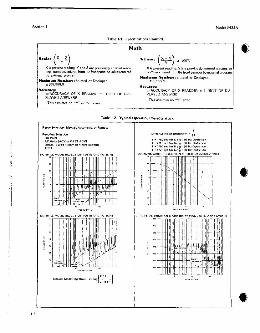
Scale: (X ~ z)X is present reading. Y and 2 are previously entered readings, numbers entered from the front panel or values enteredby external program.
Madmum Number: (Entered or Displayed)±199,999.9
Accuracy:±(ACCURACY OF X READING ±1 DIGIT OF DISPLAYED ANSWERjI
'This assumes no "Y" or "2" error.
% Error: (X ~ Y) x 100%
X is present reading. Y is a previously entered reading, ornumber entered from the front panel or by external program.
Maximum Nu.ber: (Entered or Displayed)±199,999:9
Accuracy:±(ACCURACY OF X READING ± 1 DIGIT OF DISPLAYED ANSWER)'
'This assumes no "Y" error.
Table 1-2. Typical Operating Characteristics.
!!~. '
Range Selection: Manual, Automatic, or Remote
Function Selection:DC VoltsAC Volts (ACVor FAST ACVIOHMS (2 wire kilohm or 4 wire kilohm)TeST
NORMAL MODE REJECTION (50 Hz OPERATION)70
601-----.+---.++++1-++1--+-++11-++++l--+++-H
50
;;;""s 40
~~ ~z /,0
i 30
~20
"Y L"v
10 GOIGH5 DIGIT [;.::OPEU /IPrIERA~
10 100
FA€QUENCY IHll
NORMAL MODE REJECTION (60 HZ OPERATION)70
60 1---.jf.--l-1--H++IH--I-H+I-++H---t--t-Jf-H
50 1----I1-1-+-H-H-Ir+--t-H+hlt+H--t--t-H-i
6 DIGIT
OPEAt~
10 100FREOUENCY (Hzl
1Effective Noi58 Bandwidth = 2T
T = 1/00 sec for 5 .digit 00 Hz OperationT =2/15 sec for 6 digit 60 Hz OperationT = 1/50 sec for 5 digit 50 Hz OperationT = 4/25 secfor 6 di~it 50 Hz Operation
COMMON MODE REJECTION (1 KILOHM IMBALANCE)ISO .
140 I--kd:-l..j-j-,fffi-~H+J-+++H--+-+Ht-Htt--Hi
t-,130 r-,
~ 120z0 1'-,i "0 r-,
100
r-.90 r-,
.010 100
FREQUENCY 1Hz!
EFFECTIVE COMMON MODE REJECTION (50 Hz OPERATION)180 .
1701--++-1+
160
150
140 60lGI1
~IOPERATION
I'-.130 r-.
! I'SOIGIT120 OPERATION
~W"'-f--110
•
1-6
111 f T INormal Mode Rejection = 20 log ---sin 11f T
10
FREOUENCY IHII
100
•

Section I
Overload Indication: OLOperating Temperature: OOC to 50°CWarmup Time: One hour to mee~ all spec~fications
Humidity Range: < 95% R6H.,
0 C tg 40 CStorage Temperature: -40 C to +75 C
Power: 100/120/240 V +5%, -10% 48 Hz to 400 Hz lineoperation < 60 VA
220 V ± 10% 48 Hz to 400 Hz line operation<60VA
Dimensions: 88.9 mm high x 425.5 mm wide x 527.1mm deep (3'1," high x 16'%" wide x 20'%" deep)
Weights: Net - 9 kg (21 lbs.lShipping - 12 kg (26 lbs.l
General (Auto Cal must be 'on for 75 seconds to meet allspecifications)
table 1-2. Typical Operating Characteristics (Cont'd).
~~I6 DIGIT
~ERATION
I"
NATiOJ
JI
130
150
110
160
140
120
~zo
i
170
Model 3455A
EFFECTIVE COMMON MODE REJECTION (60 Hz OPERATION)180•
10 100
FREQuENCY lHzl
Typical HP-IB Handshake Times:Accept Data - (3455A addressed to listen or ATN true)
500 /lsec per character typical (0 delay source)
Output Data - (3455A addressed to talk)250 usee per character typical (0 delay acceptor)
• 1-21. SAFETY CONSIDERATIONS.
1-22. The 3455A is a safety class I instrument (providedwith a protective earth terminal). The instrument and manual should be reviewed for safety symbols and instructionsbefore operation.
I
fA~
1-7

Section I
Table 1-3. Recommended Test Equipment.
Instrument Critical Specification Recommended Model Use
DC Voltage Standard Voltage: 10 mV to 1000 V Systron Donner PATAccuracy: ± .005% Model Ml07
AC Calibrator Frequency: 20 Hz to 100 kHz -hp- Model 745A PATOutput Level: 100 mV to 1000 V AC CalibratorAccuracy: ± .1 % -hp- Model 746AVoltage Stability (6 mos.l ± .02% High Voltage Amplifier
Test Oscillator Frequency: to 250 kHz -hp- Model 652A POutput: 3 V rms into 50 n Test OscillatorFrequency Response ± .25%
Resistance Decade Resistance: 100 n to 10 Mn Gen Rad Model PATAccuracy: ± .004% GR 1433-Z Decade
Resistor
DC Null Voltmeter Voltage Range: 1 J.lV to 10 V -hp- Model 419A PAT
Reference Divider Division Ratio Accuracy ± .001 % Fluke Model 750A PAOutput Voltage Range - 1 V to 1 kV Reference Divider
DC Transfer Standard Output Voltages; 1 V, 1.018 V, Fluke Model 731A PA1.019\1,10 V DC Transfer Standard
Accuracy: ± 5 ppmStability: ± .001% (30 days)
Electronic Counter 50 Hz to 60 Hz -hp- Model 5300A/5302A PMeasuring System
Resistance Standard Resistance: 1 knGuildine Model A
Accuracy: ± .0005%9330/1 K or 9330A/l K
Resistance: 100 KAccuracy: ± .002% Guildline Model 9330/100 K
Bus System Analyzer HP-IB Control Capability -hp- Model 59401 A TBus System Analyzer
Calculator HP·JB Control Capability must -hp- Model 9825A OTserve as printer for 3455AOutput data.
Oscilloscope Bandwidth: DC to 10 MHz -hp- Model 180C/D TSweep Time: 0.1 J,lS to 1 sec/div Oscilloscope withSensitivity: 1 V/div 1801Aand 1821A
plug-in units
Digital Voltmeter Voltage Range: 10 mV to 1000 V -hp- Model 3490A PATResolution: 10 J,lV
Resistors Resistances: -hp- Part No.1 kn ± 10% 0684-102110 kn ± 0.1% 0698-4157 P1 Mn ±0.1% 0698-6369
Signature Analyzer -hp- Model 5004A T
Model 3455A
•
1-8
P = Performance ChecksA = Adjustments
T = Troubleshootingo = Operators Check
•

•Model 3455A
SECTION II
INSTALLATION
2-1. INTRODUCTION.
2-2. This section contains information and instructionsnecessary to install and interface the Model 3455ADigital Voltmeter. Also included are initial inspectionprocedures, power and grounding requirements, environmental information, and repackaging instructions.
2·3. INITIAL INSPECTION.
~40V~ ~40V~220V 220V
lDO\' IOOV120 120V
240VOlh 220 Volts
@40V~ ~40~220\1 220V
KlOV KlOV120V 120V
120 Volls 100 Volli
Section II
•
2-4. This instrument was carefully inspected bothmechanically and electrically before shipment. It shouldbe free of mars and scratches and in perfect electricalorder. The instrument should be inspected upon receiptfor damage that might have occurred in transit. If theshipping container or cushioning material is damaged, itshould be kept until the contents of the shipment havebeen checked for completeness and the instrument hasbeen mechanically and electrically checked. Proceduresfor testing electrical performance of the 3455A are givenin Section IV. If the contents are incomplete, if there ismechanical damage or defect, or if the multimeter doesnot pass the Performance Tests, notify the nearestHewlett-Packard Office. (A list of the -hp- Sales andService Offices is presented at the back of the manual.)If the shipping container is damaged, or the cushioningmaterial shows signs of stress, notify the carrier as wellas the Hewlett-Packard Office. Save the shippingmaterials for the carrier's inspection.
2-5. PREPARATION FOR USE.
2·6. Power Requirements.
2-7. The Model 3455A requires a power source of 100,120, 220, or 240 V ac (+ 5070 - 10%),48 Hz to 400 Hzsingle phase. Maximum. pooler consumption is 60 VA.
2·8. Line Voltage Selection.
2-9. Before connecting ac power to the 3455A, makesure the rear panel line selector switches are set to correspond to the voltage of the available power li~e.asshown in Figure 2-1. Also, be sure the proper fuse IS 10
stalled. The multimeter is shipped with the line voltageand fuse selected for 120 V ac operation.
Be sure the 50 - 60 Hz rearpanel switch isset for the proper line frequency for yourlocation.
NOMINAL OPERATING RANGEVOLTAGE - 10%, + 5% of nominal FUSE
100 volts 90 to 105 volts 0.5 A120 volts 108 to 126 volts 0.5 A220 volts 198 to 231 volts 0.25 A240 volts 216 to 252 volts 0.25 A
Figure 2·1. Line Voltege Selection.
2·10. Power Cable.
2-11. Figure 2-2 illustrates the standard configurationsused for -hp- power cables. The -hp- part numberdirectly below each drawing is the part number for apower cable equipped with a connector of that configuration. If the appropriate power cable is not included with the instrument, notify the nearest -hp- Salesand Service Office and the proper cable will be pro-vided. .
2·12. Grounding Requirements.
2-13. To protect operating personnel, the NationalElectrical Manufacturer's Association (NEMA) recommends that the instrument panel and cabinet begrounded. The Model 3455A is equipped with a threeconductor power cable which, when plugged into an appropriate receptacle, grounds the instrument.
2-14. Bench Use.
2-15. The Model 3455A is shipped with plastic feet andtilt stands installed and is ready for use as a bench instrument. The plastic feet are shaped to permit "stacking" with other full-module Hewlett-Packard instruments. The tilt stands permit the operator to elevatethe front panel for operating and viewing convenience.
2-16. Rack Mounting.
2-17. The Model 3455A may be rack mounted by adding rack mounting kit Option 908 or Option 909. Option908 contains the basic hardware and instructions for
2-1

Section II Model 3455A
POWER CORDS
@ G!lJE3 G3 [Q]~* ~*• • ~N' ~e: N L • •• L N
AUSTRALIA DENMARK EUROPE GREAT BRITAIN SWITZERLAND UNITED STATES UNITED STATES120V 240V
Country Part Number Opt. Voltage
Australia 8120-1369 961 250V 6ADenmark 8120·2956 912 250V 6AEurope 8120-1689 902 250V 6AGreat Britain 8120-1351 900 250V 6ASwitzerland 8120-2104 906 250V 6A"United States 8120-1378 903 120V 10A"United States 8120-0698 904 240V 10A
Power cords supplied by HP have polarities matched to the power input socket on the instrument:
• L = Line or Active Conductor (also called "live" or "hot").• N = Neutral or Identified Conductor• E = Earth or Safety Ground
NOTE: Plugs are viewed from connector end. Shape of molded plug may vary within country.
• CSA certification includes only these Power Plugs
2-20. Address Selection. The HP-IB address switch,located on the rear panel, permits the user to set the"talk" and "listen" address of the instrument. The talkand listen address is a 7-bit code which is selected to provide a unique address for each bus instrument. The3455A normally leaves the factory with the addressswitch set to a "Listen" address of 6 and a "talk" address of V. The address switch also allows selection of a"talk-only" mode. Refer to Paragraph 3-42 for addressselection instructions.NOTE
Figure 2·2. Power Cord Configurations.
rack mounting; Option 909 adds front handles to the must not exceed 2 meters (6.5 ft.) times the number ofbasic rack mount kit. The rack mount kits are designed instruments to be connected, or 20 meters (65.6 ft.),to permit the Multimeter to be installed in a standard 19 whichever is less.inch rack. When rack mounting, additional supportmust be provided at the rear of the instrument. Be surethat the air intake at the rear of the instrument isunobstructed.
2·18. Interface Connections.
2-19. The Model 3455A is compatible with the HewlettPackard Interface Bus (HP-IB).
HP-IB is Hewlett-Packard's implementationofIEEE std 488-1975, "Standard Digital Interface for Programmable Instrumentation ':
2-21. External Trigger. A BNC connector, located onthe rear panel, is provided for an external trigger input.The trigger input is to be driven with TTL level signals.
The Multimeter is connected to the HP-IB by connecting an HP-IB interface cable to the 24-pin connectorlocated on the rear panel. Figure 2-3 illustrates typicalHP-IB system interconnections and shows the1063IA/B/C HP-IB Interface Cable connectors. Eachend of the cable has both a male and female connectorto simplify interconnections of instruments and cables.As many as 15 instruments can be connected by thesame interface bus; however, the maximum length ofcable that can be used to connect a group of instruments
2·22. ENVIRONMENTAL REQUIREMENTS.
WARNING ITo prevent electricalshock orfire hazard, donot expose the instrument to rain ormoisture. •
2-2

•Model 3455A
Figure 2·3. Typical Hp·IB System Interconnections.
Section II
•
•
2·23. Operating and Storage Temperature.
2-24. In order to meet the specifications listed in TableI-I, the instrument should be operated within an ambient temperature range of 23°C ± 5°C (73of ± 9°F).The instrument may be operated within an ambienttemperature range of O°C to + 55°C (+ 32°F to+ 131°F) with degraded accuracy.
2-25. The instrument may be stored or shipped wherethe ambient temperature range is within - 40°C to+ 75°C (-40°F to + 167°F). However, the instrumentshould not be stored or shipped where temperature fluctuations cause condensation within the instrument.
I
2·26. Humidity.
2-27. The instrument may be operated in environmentswith relative humidity of up to 95%. However, the instrument must be protected from temperature extremeswhich cause condensation within the instrument.
2-28. Altitude.
2-29. The instrument may be operated at altitudes up to4572 meters (15,000 feet).
2-30. REPACKAGING FOR SHIPMENT.
NOTE
If the instrument is to be shipped to HewlettPackard for service or repair, attach a tag tothe instrument identifying the owner and in:'dicating the service or repair to be accomplished. Include the model number andfull serial number of the instrument. In anycorrespondence, identify the instrument bymodel number and full serialnumber. Ifyouhave any questions, contact your nearest-hp- Sales and Service Office.
2-31. The following is a general guide for repackagingthe instrument for shipment. If the original container isavailable, place the instrument in the container with appropriate packing material and seal well with strongtape or metal bands. If the original container is notavailable, proceed as follows:
a. Wrap instrument in heavy paper or plastic beforeplacing in an inner container.
b. Place packing material around all sides of instrument and protect panel race with cardboard strips orplastic foam.
c. Place instrument and inner container in a heavycarton and seal with strong tape or metal bands.
d. Mark shipping container "DELICATE INSTRUMENT", "FRAGILE", etc.
2-3

Section III Model 3455A
I.
CDCD
CDCD
FRONT PANEL
Line Switch, push on/push off
HP-IB' status indicators:SRQ - indicates that the 3455A "requires service" fromthe controller. Refer to Paragraph 3-78.LISTEN - lights when the 3455A is addressed to"listen".TALK -lights when the 3455A is addressed to "talk".REMOTE - lights when the 3455A is under HP-IBcontrol.
LOCAL 1>witch- permits the operator to return theinstrument to local (front panel) control.
Display - Indicates polarity and amplitude of themeasurement. Measurement results are presented in either5-1/2 digits or 6-1/2 digits depending upon whether theHIGH RESOLUTION feature is off or on. An LED in theupper left corner of the display indicates sample rate ofthe 3455A. Five LED's, located to the right of the display, indicate whether the display is presenting DC Voltage, AC Voltage, Ohms, Scale or % error measurementresults.
Range Selection Keys - permit selection of ranges asfollows:DC Volts: .1 V,l V, 10 V, 100 V, 1 kV, AUTOAC Volts: 1 V, 10 V, 100 V, 1 kV, AUTOOhms:.l K, 1 K, 10 K,100 K,l,OOO K, 10,000 K, AUTOLED's located in the center of the keys indicate whichrange is selected.
Function Selection Keys - DC Volts, AC Volts, FASTAC Volts, 2 WIRE kn, 4 WIRE kn, and TEST. LED'slocated in the center of the keys indicate which functionis selected.
Auto Cal switch - allows the Auto-Cal feature to be turned on or off. LED in center of Key indicates Auto-Cal on.Refer to Paragraph 3-29.
®
@
@
@
®
@
®
Data Ready Request Indicator - lights when the DataReady Request feature is programmed on. Refer toParagraph 3-65.
High Resolution switch - switches display from 5-1/2digit presentation to 6-1/2 digit presentation. An LEDlocated in the center of the key indicates High Resolution on when lit.
Trigger Selection Keys - permits selection of INTERNAL, EXTERNAL, or HOLD/MANUAL trigger. Eachkey has an LED which lights to indicate the trigger sourceselected.
Sample Rate Controls - permit selection of maximumsample rate or the present sample rate divided by 2. Themaximum sample rate may be divided by 2 up to 6 timesfor a minimum sample rate of: maximum sample rate
64
Binary Program Indicator - indicates when the 3455A isoperating in the Binary Program mode. Refer toParagraph 3-66.
Math Controls - Select SCALE (X - Zl , % ERRORy y
(~x 100), or MATH OFF. The Math feature selectedy
is indicated by an LED located in the key (Paragraph3-19).
ENTER controls - Recall the number stored in the Y or Zregister to the display, also "shifts" the front panelkeyboard to permit entry of new data to be stored in theY or Z registers (Paragraph 3-23).
STORE Controls - The Store controls transfer thenumber presently being displayed into the Y or Z register(Paragraph 3-231.
Rear Terminal Indicator - indicates when the rear inputterminals have been selected. •Figure 3-1. Front and Rear Panel Features.
3-0

•Model 3455A
SECTION III
OPERATING INSTRUCTIONS
Section III
3-1. INTRODUCTION.
3-2. This section contains information and instructionsnecessary for operation of the Model 3455A DigitalVoltmeter. Included is a description of operationcharacteristics, a description of the operating controlsand indicators, and functional checks to be performedby the operator.
3-3. OPERATING CHARACTERISTICS.
3-4. Turn-On and Warm-Up.
3-5. Before connecting ac power to the 3455A, makecertain the rear panel line selector switches are set tocorrespond to the voltage and frequency of the availablepower line and that the proper fuse is installed for thevoltage selected. For rated measurement accuracy, the3455A should be allowed to warm up for at least onehour.
3·6. Self Test Operation.
3-7. The internal test function of the 3455A verifies theoperation of the de analog circuitry, inguard andoutguard logic circuitry, and the front panel indicatorsand display. The primary test of the de analog circuitryis the measurement of various Auto-Cal constants. Alogic check is also performed, when all the cal constantmeasurements are taken. The logic check consists of adummy cal constant calculation made in the outguard
logic of the instrument. When all these measurementsand calculations are completed, the 3455A will display+ .8.8.8.8.8.8.8. and the self-test operation will startagain. In order to bring the instrument out of this mode,any other function button must be pressed.
3-8. In the event of a cal constant failure, the Self-Testoperation will stop and the failing cal constant's numberwill be displayed (an integer number from 13 to 0). Ifthe dummy calculation fails, a non integer number isdisplayed (e.g., 9.998 or 10.002 etc.).
3-9. The Self-Test function can be remotely programmed, as described in the programming portion of this section. The 3455A will output a 10 upon a successful completion of the test and if addressed to "talk." If thedummy calculation fails, the answer of the dummycalculation will be the output (9.998 or 10.002 etc.), Ifany auto-cal constants fail, the 3455A will not outputany readings, (times out).
NOTE
The self test feature does not test operationof the ohms or ac sections nor the measurement accuracy of the 3455A.
3·' O. DC Voltage Measurement
3-11. The Model 3455A measures de voltage from Imicrovolt to 1000 volts in five ranges extending from .1
®®®@
®@@®@@
Ohms Signal Terminals - supplies drive signal for4-WIRE Ohms measurements (Paragraph 3-121.
Input Terminals
GUARD switch - internaily connects the Guard terminalto the LOlnput terminal (for front panel operation only,Paragraph 3-411.
GUARD Terminal
REAR PANEL
Ohms Signal Terminals
Input Terminals
Guard Terminals
Front/Rear INPUT SELECT switcb
HP-IB' Connector - see Paragraph 2-1 8 and 3-48.
AC or AC/DC Input Selection switch - refer to Paragraph3-14.
®@@®®®®®
Line Frequency Selection Switch - must be set to correspond to the power line frequency (50 Hz or 60 Hz).
Reference Module
EXTERNAL TRIGGER Input Connector
HP-IB' Address Selection Switch - refer to Paragraph3-53.
Cooling Fan
Power Line Voltage Selection Switches - refer to Paragraph 2-8.
Fuse - 90 V to 126 V - 0.5 amp, 198 V to 252 V 0.25 amp.
AC Power Connector.
*HP-IB is Hewlett-Packard's implementation of IEEE Std.488-1975, "Standard Digital Interface for ProgrammableInstrumentation".
Figure 3-1. Front and Rear Panel Features (Cont'dl.
3-1

Section III
4·WIRE MEASUREMENT
INPUT GUARD
SIGNALCURRENT Rx
.-J
2·WIRE MEASUREMENT
Rx
SIGNAL~CURRENT
3455-8 -4667
Model 3455A
Figure 3-2. Ohmmeter Measurement Connections.
volt full-scale to 1000 volts full-scale. Measurementresults are presented in 5-1/2 digits during normaloperation or in 6-112digits when the 3455A is set to theHigh Resolution mode. All ranges except the 1000 voltrange have 500/0 overrange capability and are overloadprotected from input voltages up to ± 1000volts. Inputresistance in the de function is greater than 1010 ohmson the .1 V, IV, and 10 V ranges and equal to 10megohms on the 100 V and 1000 V ranges. Refer toTable 1-1 for DC Accuracy specifications.
3-12. Resistance Measurement.
3-13. The Model 3455A measures resistance from ImiIliohm to 15 megohms in six ranges extending from .1kilohms ful scale to 10,000 kilohms full scale. Measurement results are presented in 5-1/2 digits during normaloperation or in 6-112digits when the 3455A is set to theHigh Resolution mode. The only exception is that the .1V range can only take a measurement in the 5-1/2 digitmode. Resistance may be measured in "4-WIRE" configuration for optimum accuracy or "2-WIRE" configuration may be selected for measurement convenience. Figure 3-2 shows proper connections for makingresistance measurements. The nominal output signalcurrent on the .1 kilohm, I kilohm and 100 kilohmranges is .7 rnA. The nominal output current on the1000 kilohm and 10,000 kilohm ranges is .7 microamp.Maximum output voltage is limited to less than 5 voltson all ranges. Refer to Table 1-1 for ohm accuracyspecifications.
3·14. AC Voltage Measurement
3-15. The -hp- Model 3455A offers a choise of trueRMS (standard unit) or average responding ac convertors (Option 001). Both methods measure ac voltagesfrom 10 microvolts to 1000 volts in four ranges extending from 1 volt to 1000volts ranges. All ranges, exceptthe 1000 volts range, have 50% overrange capability andare protected from input voltage components up to 1000
3-2
volts RMS. Readings taken in the ac function aredisplay in the 5-1/2 digit mode only. Input impedanceof both convertors is 2 megohms in parallel with< 75 pF for rear terminal input and < 90 pF for frontterminal input. In addition to the normal ac volts function, the 3455A also has a fast ac volts function. Thefast ac function has a faster ac reading rate than the normal ac function.
3-16. The frequency response of the true RMS convertor is from 30 Hz to 1 MHz in the normal ac volts function and from 300 Hz to 1 MHz in the fast ac volts function. Both ac signals or ac plus de signals (ac signalssuperimposed on a de level) can be measured by the trueRMS convertor. Selection of the ac or ac + de inputsare chosen by a switch located behind the rear panelsreference cover. Refer to Table 1-1 for accuracyspecifications of each ac mode.
3-17. The frequency response of the average converteris from 30 Hz to 250 Hz in the normal ac volts functionand from 300 Hz to 250 kHz in the fast ac volts function. Only ac signals (no de component) can bemeasured by the average converter. Refer to Table 1-1for accuracy specification of each ac mode.
3-18. In order to get accurate ac readings (especiallywith high voltage inputs at high frequencies), the low input terminal (front and rear) should be connected to theguard terminal (front and rear). Refer to paragraph 3-39for guarding information.
NOTE
The front panel guard pushbutton appliesonly for front panel inputs. Be sure to wirerear panel guard connections yourself, if using the rear panel input terminals.

Model 3455A
3-19. Math Faature.
where R = Resistor across the input terminalsV = Voltage drop across the resistor
3-20. The math feature of th 3455A allows the measurement value to be offset and/or scaled by known valuesor to be expressed in percent of a reference value.
.1475 Ky
1 K- .8525 Ky
unknown resistance in ohmsx-R-1-
25 = x-zy
x-zy-
Section III
When x = the Lower Limit, the DISPLAY should-200,000
When x = the Upper Limit, the DISPLAY should+ 200,000
therefore, -200,000 = Lower Limit - zy
and + 200,000 = Upper Limit - zy
d. Limit Testing: The Scale mode of the 3455A canalso be used to do Limit Testing. This can be accomplished since the largest number which can be
displayed is + 200,000 and the smallest number is-200.00. If the magnitude of the display exceeds200,000, either a "+ LL" or a "-LL" is displayed.Therefore, the "y" and "z" constants must be chosenso that when "x" (the reading) is equal to the upperlimit, the display is + 200,000 and when "x" is equal tothe lower limit, the display is -200,000. This can be accomplished as follows:
where x = total measured resistance including RR = lead resistance
3455A measurement results are expressed in kilohm andis entered in the "z" register to remove the offset atO°c. The measurement result of the 3455A is scaled toread directly in degrees centigrade by solving the equation for the value of "y". This is done where the resultsof the equation are equal to 25°C since the sensorresistance is specified at that temperature. The scaleequation becomes:
solving for y:y = .1475 K = .0059 with this number25
entered in the "y" register, the 3455A measurementresult will be presented directly in °C.
c. Accurate 2 Wire Ohm Measurement: When tryingto make an accurate 2 wire ohm measurement, the inputlead resistance and the internal resistance of the 3455Ashould be subtracted out from the reading. This is doneby setting the instrument to the desired range and shortthe input leads at the measuring point. Store a 1 in "y"and store the input lead resistance reading in "z". Openthe input leads and connect the unknown resistor to theleads. With the 3455A set in the Scale mode, the valueof the unknown resistor is displayed without the inputlead resistance. Since a 1 is stored in "s" and the leadresistance (R) is stored in "z", the scale equation.becomes: .
V 0 0110If = current In mi lampsV-O-y-
x-zy
b. Temperature Measurement: A temperature mesurement can be made by using a line or resistivetemperature sensor.
Assume that the sensor has a resistance of 1 kilohm at25° C and changes 5900 pprn/" C. At 0° C the sensorwould have a resistance of 852.5 ohm (1 kilohm - [5.9ohms] 25). This number is divided by WOO since the
a. Current Measurement: Accurate currentmeasurements can be made by using a low value resistorshunting the 3455A's input terminals. The value of theresistor is then entered in the "y" register (seeParagraph 3-22), and zero is entered in the "z" registerWith the resistor connected at the input terminal and theinstrument set in the voltage mode, currentmeasurements can now be made. You can do this byconnecting the input across the resistor and measuringthe voltage drop across the resistor. This voltage drop isproportional to the current through the resistor. Byswitching the 3455A to the scale mode, the readingbecomes an accurate current reading in milliamps. Sincethe resistor value is in kilo ohms (R) and stored in "y" ,and since zero is stored in "z", the scale equationbecomes: I
3-21. Scale Mode. The scale mode of the math feature isdescribed by the formula: result = ~ where x is the
ymeasurement value, z is the offset value, and y is thescale factor. This mode allows the measurement value tobe modified by the addition, subtraction, multiplicationor division of a known value. Addition and subtractionare performed by entering the number to be added orsubtracted in "z" and entering 1 in "y". The scale formula then becomes: result = x - (± z) = x - (± z),
1Division is performed by entering 0 in "z" and thedivisor value in "y." The scale formula thenbecomes: result = x - 0 =~ Multiplication is perform-
y yperformed by dividing the measurement value by the inverse of the multiplier value; that is, multiplication isperformed by dividing by a fraction. The scale formulabecomes: result = x - 0 = xy. As an example: to
l7Ymultiply by 10, divide by the inverse of 10 which is 1/10or .1. Various examples using the scale mode are asfollows:
•
•
•
3-3

r\,
Section III Model 3455A
This leaves two equations to solve for the unknown "Y"and "z" constants. The two constants can be found thefollowing way:
The following is an example of how to use this mathtechnique. In this example a DC voltage is measuredand compared with a Lower Limit of 10 volts and anUpper Limit of 30 volts:
By entering oo5סס. into the "y" register and 20 into the"z" register, and then pushing the SCALE and DCVbuttons, the 3455A becomes a limit testing DVM. If theinput exceeds 30 volts a II + LL" is displayed, and if theinput is less than I0 volts a «,LL" is displayed. If the input is within the limits set, a number is displayed.
3-25. The STORE keys are used to transfer the numberpresently being displayed in the "Y" or "Z" memoryregisters and to return the voltmeter to normal operation.
3-28. When the 3455A is used in the HIGH RESOLUTION mode, the instrument changes from a 5-1/2 digitmeasurement to a 6-1/2 digit measurement. Thischanges the measurement resolution from 10 parts/1.5million (5-1/2 digit mode) to I part/1.5 million (6-1/2digit mode). The integration period will also changefrom 1/60 second (1/50 second for 50 Hz operation) to8160 second (8/50 second for 50 Hz operation). TheHigh Resolution mode cannot be used in the AC modeor the .1 V DC and I K ohm ranges. The reading rate inthe DC and Ohms mode will also increase when the •High Resolution function is turned off. Table 3-1 givesthe various reading rates of the DC and Ohms functions
3-27. High Resolution Mode.
3·23. Enter and Store.
The operation of the ENTER and STOREkeys are not mutually exclusive. That is, thenumber being displayed may be stored ineither the Y or Z register independently ofthe register selected by the ENTER keys.
3-24. The "Y" and "Z" ENTER keys have two functions. When one of the enter keys is pressed, the numberpresently stored in the respective memory register isdisplayed on the front panel readout. This allows theoperator to check the contents of the "Y" or "Z"memory registers. Pressing the enter key also "shifts"the front panel keyboard, disabling all keys except thoselabeled in blue. These keys can now be used to enter thedesired values to be stored in the "Y" or "Z" memoryregisters. As the value is entered it is displayed on thefront panel readout. Numerical values from .o00ooo to+ or - 199,999.9 may be entered in either the Y or Zregisters.
NOTE
3-26. The following describes how the ENTER andSTORE features may be used:
a. To view the value presently in memory, press theENTER key of the appropriate register (ENTER Y orENTER Z). To return this number to memory, press theSTORE key of the appropriate register.
b. To enter a new number, press the ENTER key of tthe register to receive the number. Enter the desirednumber into the display by pressing the keys labeled inblue. Store the number entered by pressing the STOREkey of the appropriate register.
c. To enter a measurement value presently being.displayed, press the STORE key of the desired registerrv or Z).
10 = 20
= oo530סס. - 10
400,000
Lower Limit = 30 +2
Lower Limit - z= Upper Limit - z= Lower Limit + Upper Limit -2Z
(add these two equations)
Upper Limit + Lower Limit2
Upper Limit - zy
y =and,
200,000 (y) =Upper Limit _ Upper Limit + Lower Limit
2Upper Limit - Lower Limit
2Upper Limit - Lower Limit
400,000
therefore, z
200,000
y = Upper Limit - Lower =
400,000
z = Upper Limit +2
-200,000 (y)+ 200,000 (y)
o
3-22. % Error Mode. The % error mode of the mathfeature is described by the formula: result in %~x
'y100, where "x" is the present measurement value and
"y" is the reference value. An application of thisfeature might be an inspection test of resistors. Thisnominal resistor value would be entered in the "y"register in kilohm (3455A) resistance measurements arepresented in kilohm). As an example, assume the test ismade on a group of 750 ohm resistors with a toleranceof 5%. The nominal resistor value (750 ohms) is enteredin the "y" register as .750. The % error equationbecomes: result in % = x-.750 x 100. A resistor with
.750an actual value of 790 ohms would give a measurementresult of: % error = .790-750 x 100 = 5.33333%,
750indicating the resistor is out of tolerance by .33333%.
3-4

Section III
These numbers are accumlative when Auto-Cal is on.
measurement cycle is completed, the delayed trigger williniate a second measurement cycle. Only one trigger willbe delayed during any given measurement cycle. Any extra triggers sent during this cycle will be ignored.
3·36. Sample Rate (Display).
3-37. The SAMPLE RATE of the 3455A is set internally and depends on the function selected, the power line
1283264
86416
Maximum Number of CalConstant Termination -
Function
DCDC (High ResolutionlAC FastAC NormalOhmsOhms (High Resolution)
c. Hold/Manual Trigger: This trigger is similar tothe External Trigger, except it can be executed by theHold/Manual button. The Hold/Manual button mustbe pressed once in order to place the 3455A in the Holdmode. After pressing the Hold/Manual button the second time, a measurement is taken. When the measurement cycle is completed, the Hold/Manual button canbe pressed again for a new reading. It is important toremember that the Hold/Manual button should bepushed twice in order to take the first reading. If triggered while a measurement is taken, the trigger isdelayed until the measurement cycle is complete. Thedelayed trigger will initiate a second measurement cycle,when the first one is completed. Only one trigger will bedelayed during any given measurement cycle. Any extratriggers sent during this cycle will be ignored.
3-35. Auto-Cal constants measurements also depend onthe Trigger mode used. An input reading and a cal constant measurement will alternately be taken, when the3455A is in the Internal Trigger mode. A typical sequence would be an input reading, one cal constantmeasurement, another input reading, the next cal constant measurement, and so on. An attempt of this sequence (input reading/cal Constant measurement). isalso made when the instrument is in the Hold/Manualor External Trigger modes. If, however, a trigger isreceived while a cal constant measurement is taken, thismeasurement is aborted and an input reading. is taken.After this reading, the aborted cal constant measurement is then retaken. If a new trigger is received beforethe cal constant measurement is finished, the measurement is again aborted and a new input reading is taken.The cal constant measurement can be aborted a numberof times, depending on the function of the instrument.The table below lists the number of times the cal constant measurements can be aborted. After this numberhas been reached, the trigger will be delayed and theAuto-Cal constant measurement is then completed.
b. External Trigger: When the 3455A is the ExternalTrigger mode, the user can trigger the instrument froman external trigger pulse. This trigger pulse has to be applied to the rear External Trigger Connector and shouldhave a negative TTL edge and must be at least 3 secondswide. The instrument will take a measurement, whenthis trigger pulse is received. After the measurement istaken, the 3455A can be triggered again for a newreading. If the instrument is triggered while making ameasurement, the new trigger is delayed. After the first
3-34. The 3455A has three trigger modes. INTERNAL,EXTERNAL, and HOLD/MANUAL. The following isan explanation of each trigger mode.
Model 3455A
3-32. The last set of constants are used to correctmeasurements, when the Auto-Cal mode is turned off.As long as the input amplifier offsets, gain linearityand drift do not vary the 3455A should remain withinit's accuracy specifications. The time period over whichthese parameters will not change may vary from instrument to instrument. When the Auto-Cal function isdisabled to obtain faster reading rates, it is recommended to periodically return the 3455A to the Auto-Calmode in order to update the cal constants. This can bedone after a block of readings have been taken or whenthe instrument is not in use. The instrument will thenupdate the cal constants for accurate measurements.Allow about 6 seconds for updating the cal constants, ifthe 3455A is in the Hold mode.
3-31. The reading rate of the 3455A increases when theAuto-Cal feature is turned off. Table 3-1 gives thereading rate of the various functions with Auto-Cal onor off.
a. Internal Trigger: TlJis trigger is generated internally and triggers the 3455A to take a reading, after theprevious operation is completed (a reading or Auto-Calmeasurement). This trigger mode is entered when the instrument is turned on, when the Internal Trigger buttonis pressed, or a Device Clear message is remotely sent.
3·33. Trigger.
3-29. Auto·Cal.
3-30 The purpose of the AUTO-CAL feature is toeliminate offsets, gain non-linearity, and drift whichmaybe present in the analog measuring circuits of the3455A. This is accomplished by measuring the offsetand gain errors and then mathematically correcting themeasurement reading to exclude them. Each of the gainand error measurements, called Auto-Cal constants, arestored in the "memory" by the 3455A's main controller. These Auto-Cal constants are usually taken between each sample of the instrument and are updatedeach time a new cal constant measurement is made.
with High Resolution turned on or off.
•
•
•
3-5

r- ~,HonIII,I'i frequency, and use of the Auto-Cal and High Resolu-i tion modes. When the Sample Rate buttons are pressed,I the display rate of the reading are changed. By depress
ing the Decrease + 2 button on the front panel, thedisplay rate can be decreased. Each time this button ispressed, the display rate is divided by two. The rate maybe divided a maximum of six times for a display rate of1/64 of the maximum rate. The 3455A can be reset tothe maximum rate by depressing the maximum button,after the display rate has been decreased. Table 3-1 givesthe maximum number of readings the instrument candisplay on the front panel, in local operation.
Table 3·1. Maximum Front Panel Reading Rates.
Model 3455A
varient inputs may cause the 3455A to constantlyuprange and downrange. If this happens, manually setthe instrument to the higher range.
3-40. Measurement time may also change, when the instrument is in the Auto Range mode. If the instrument isnot on the optimum range, a reading is taken and the3455A will either uprange or downrange. Anotherreading is then taken and if the optimum range has beenfound the reading will be displayed. If not, the instrument continues to uprange or downrange. A reading istaken on all intermediate non-optimum ranges until thecorrect range is found. The measurement time on eachrange should be added to the total measurement time.
II
I:
,I
,
i I
Func High Auto Maximum Sample RateFunction Resolution Calibration Maximum Sample Rate
DC Volts ON ON 3 readingsfsec (60 Hz)2.5 readingsfsec (50 Hz)
OFF ON 5 readingsfsec (60 Hz)3.5 readingsfsec (50 Hz)
ON OFF 6 readingsfsec (60 Hz)5 readingsfsec (50 Hz)
OFF OFF 24 readings/sec (60 Hz)22 readingsfsec (50 Hz)
Ohms ON ON 2 readingsfsec (60 Hz)1.8 readingfsec (50 Hz)
OFF ON 45 readings/sec (60 Hz)4 readings/sec (50 Hz)
ON OFF 3 readingsfsec (60 Hz)2.5 readingsfsec (50 Hz)
OFF OFF 12 readingsfsec (60 Hz)11 readingsfsec (50 Hz)
AC Volts Not ON 1.3 readings/sec (60 Hz)Applicable 1.1 readingsfsec (50 Hz)
Not OFF 1.3 readingsfsec (60 Hz)Applicable 1. 1 readingsfsec (50 Hz)
Fast Not ON 4.5 readings/sec (60 Hz)AC Volts Applicable 3.5 readingsfsec (50 Hz)
Not OFF 13 readingsfsec (60 Hz)Applicable 12 readings/sec (50 Hz)
3-38. Auto Range.
3-39. The AUTO RANGE feature of the 3455A can beused to automatically uprange and downrange the instrument to the optimum range. This action takes placewhen an input measurement is taken. Upranging is donewhen the reading is 150070 of full scale and downrangingat 14% of full scale. The Auto Range operation can beobserved by applying 1.4 volts to the input of the3455A. The range selected by the instrument is the 1 Vrange. When the input voltage exceeds 1.5 volts, the3455A upranges to the 10 V range. When the inputvoltage is decreased below 1.4 volts, the 1 V range isagain selected. The uprange points, the downrangepoints, and the accuracy of the instrument should bekept in mind when making a measurement. Time-
3-6
3·41. GUARDING.
3·42. Common·Mode Voltages.
3-43. Common-mode voltages are those which aregenerated between the power line ground point of thesource and the LO input and power line ground point ofthe 3455A. Currents caused by common-mode voltagecan be included in the measurement circuit, causingmeasurement errors.
3-44. Guard Connection.
3-45. Figure 3-3 illustrates three methods of connectingthe 3455A Guard terminal to reduce errors caused bycommon-mode voltages. In example A, Guard is atnearly the same potential as the LO measurement terminal so that currents caused by common-mode voltageflows through Guard and not the measurement circuit.In example B, the 3455A guard switch is closed connecting guard to the LO input terminal. This allowscommon-mode current to flow through lead resistanceRb causing some measurement error. This connectionmay be used if common-mode voltages are not expectedto be a problem. Example C is similar to A with the exception that connecting guard in this manner allows anycommon-mode current generated between the sourcelow and powerline ground to flow in the measurementcircuit.
NOTE
The front panel quard pushbutton appliesonly for front panel inputs. Be sure to wirerear panel guard connections yourself, ifusing the rear panel input terminals.
3-46. Guarding Information.
3-47. More detailed information on purpose andmethods of guarding may be found in -hp- ApplicationNote No. 123, "Floating Measurements and '."Guarding". This application note is available throughyour nearest -hp- Sales and Service Office.

•
Figure 3-3. Connecting the Guard.
Model 3455A
Code Interface Function
SHl Source Handshake capabilityAHl Acceptor Handshake CapabilityT5 Talker (basic talker. serial poll. talk only mode.
unaddress to talk if addressed to listen)L4 Listener (basic listener. unaddress to listen if
addressed to talk)SRl Service Request CapabilityRLl Remote/Local CapabilityPPO No Parallel Poll CapabilityDCl Device Clear Capabilityon Device Trigger CapabilityCO No Controller CapabilityEl Open Collector Bus Drivers
Interface Functions provide the means for a device toreceive, process and send messages over the bus,
3-51. The capability of a device connected to the Bus isspecified by the interface functions it has. Table 3-2 liststhe Interface Functions included in the Model 3455A.These functions are also listed above the rear panel HPIB connector (see Figure 3-1). The number following theinterface function code indicates the particular capability of that function as listed in Appendix C of IEEE Std.488-1975.
Table ]-2. HP-IB Interface Capability.
Section III
,3-52. Messages are the means by which devices exchange control and measurement information. Thesemessages permit communication and/or control between:
GUARD • lOW' ATSAME VOLTAGE
COMMON lliIOO[ CUflIMHTGO£S THAOlJQH filltl •CAUSING tMO"S
I~g~Lt!.Et!! ~~..E _
R.
R.
R.
A. BEST CONNECTION -GUARD CONNECTED TO WW AT SOI..ACE.fLOATINGp2!'~~L,( ~41.5~ _
[email protected]:-�_-----v"'-_~HIG~Hk!'~-.-1 I II I I1 I II LOW I LOWIL_ J 1
OJ-+1
I
SWFl:E GROUND ~URJ.Ji.~ ~<;!J'1D _
8. GUARD CONNECTED TO LOW AT VOLTMETER.
~a,~T~N:..PLY 34~!JAfH~:' Rll HIGHi---------I I II I II I II lDW I All Lowl
L
ISOURCEGROUNO W~W~ V:flQUtQ _
C. GUARD CONNECTEO TO EARTH GROUND.FLOATINGPOWER SUPPLY 34!5~r--"" ,-----------1..GH1@f'------vvv-_~HIG~H1t'~-.-I I II I II I II LOW. ~ LOWIL_ J I
oH-GUARDI
IIII
SOURCE GRoUNO
'.'"
•
Guard should always be connected, either tothe instrument LO terminal or to a point inthe source circuit as indicated in Figure 3-3.If the guard terminal is left open, commonmode voltages may exceed the LO-to-Guardbreakdown rating and damage the instru-ment. !
Controller and Device(s)Device and Device(s)Controller and Controller(s)
Table 3-3 lists the Bus Messages and gives a briefdescription of each. The messages are categorized byBus function.
3-53. Address Selection.
•
3-48. REMOTE OPERAnON.
]·49. General.
3-50. The Model 3455A is remotely controlled bymeans of the Hewlett-Packard Interface Bus (HP-IB).The HP-IB is a carefully defined instrumentation interface which simplifies the integration of instruments,calculators, and computers into systems.
NOTE
HP-IB is Hewlett-Packard's implementationof IEEE Std. 488-1975, "Standard DigitalInterface for Programmable Instrumentation. "
3-54. The "talk" and "listen" addresses of the 3455Aare selected by the INSTRUMENT ADDRESS switch.This switch is a seven section "Dip" switch located onthe rear panel (see Figure 3-1). The five switches, labeled1 through 5 are used to select a unique talk and listen address. Figure 3-4 lists the available address codes and thecorresponding switch settings. The 3455A normallyleaves the factory with the switch set to listen address 6and talk address V (decimal code 54).
]-55. Talk Only (No Controller). TheJ455A may be used toprovide measurement data to another device, such as aprinter, without having a controller on the Bus .However, the device must be HP-IB compatible. Thetalk only switch must be set to the TALK ONLY position. In this mode the 3455A will output measurement
3-7

Model 3455A
•
•1 POSITION (UP)
4WIRE.0 TEST
0 03455-8-47'"
5 6F5 F6
4F4
3F3
INSTRUMENTADDRESS--............
5 1
2F2
TALKONLY
ASCII CodeCharacter Address Switches 5·bi!
listen Talk A5 A4 A3 A2 Al Decimal Code
SP @ 0 0 0 0 0 00! A 0 0 0 0 1 01.. 8 0 0 0 1 0 02# C 0 0 0 1 1 03$ D 0 0 1 0 0 04% E 0 0 1 0 1 05& F 0 0 1 1 0 06
G 0 0 1 1 1 07( H 0 1 0 0 0 08) I 0 1 0 0 1 09. J 0 1 0 1 0 10+ K 0 1 0 1 1 11
L 0 1 1 0 0 12- M 0 1 1 0 1 13
N 0 1 1 1 0 14I 0 0 1 1 1 1 150 P 1 0 0 0 0 161 Q 1 0 0 0 1 172 R 1 0 0 1 0 183 S 1 0 0 1 1 194 T 1 0 1 0 0 205 U 1 0 1 0 1 216 V 1 0 1 1 0 227 W 1 0 1 1 1 238 X 1 1 0 0 0 249 Y 1 1 0 0 1 25
Z 1 1 0 1 0 26( 1 1 0 1 1 27
< \ 1 1 1 0 0 28= I 1 1 1 0 1 29> - 1 1 1 1 0 30
GUARD switch, and SAMPLE RATE switches, areprogrammable from the Bus. The program codes foreach control are listed in Table 3-4. The program codescan also be determined from the front panel markings.For multi-control features such as FUNCTION,RANGE, TRIGGER, and MATH the program codeconsists of the combination of the underlined letter inthe control group heading and the position number ofthe particular control. See the following example:
CONTROL GROUP CODE(UNDERLINED) ~
( fASf UNcno2~'RE~V -v ....v kGo 000
POSITION 1PROGRAM F1CODE
.,""n~~8~~ INOT USED
Functions Message Description
Device Data Transfers device-dependent infor-Communications mation from one device to one or
more devices on the Bus.
Device Trigger Causes a group of selected devicesControl to simultaneously intitate a set of
device-dependent actions.
Clear Causes an instrument to be set toa pre-defined state (a certainrange, function, etc. I.
Remote Permits selected devices to be setto remote operation, allowingparameters and device characteris-tics to be controlled by BusMessages.
Local Causes selected devices to returnto local (front panel) operation.
Local Disables local (front panel) con-Lockout trois of selected devices.
Clear Returns all devices to local (frontLockout panel) control and simultaneouslyand clears the Local Lockout Message.Local
Interrupt Require Indicates a device's need for inter-and Service action with the controller.DeviceStatus Status Presents status information of a
Byte particular device; one bit indicateswhether or not the device current-ly requires service, the other 7bits (optional) are used to indi-cate the type of service required.
Status A single bit of device-dependentBit status information which may be
logically combined with status bitinformation from other devicesby the controller.
Passing Pass Passes bus controller responsibili-Control Control ties from the current controller to
a device which can assume theBus supervisory role.
Bail Abort Unconditionally terminates BusOut communications and returns con-
trol to the system controller.
Table 3·3. Bus Messages.
NOTE
Section III
When the 3455A is connected to a systemwith a controller, the TALK ONL Y switchmust be set to the off position.
3·5&. Program Codes.
data each time a measurement sample is made. Sectionof FUNCTION, RANGE, TRIGGER, etc. is accomplished manually using the front panel controls.
. ,'1
3-57. All front panel controls, except the LINE switch,
3-8
Figure 3-4. Address Selection.

'I!
Model 3455A
Table 3-4. HP-IB Program Codes.
3-59. Program codes for the ENTER and STOREfeatures consist of the letter underlined in the control
HIGH RESOLUTIONon
AUTOCAL off
3455A ProgramInformation~
"FI R3 M HI M3 T3"
~HOLO/MANUALTRIGGER
MATH off
control group code(underlined)
£~ ""~TOREcontrol COdes........roT 1: Or Ol(underlined) 0
Example:
'------ 10 V RANGE
L..-__ DC Volts FUNCTION
Program data message using the 9830A Calculator.
3·83. Programming. The 3455A is programmed by meansof data messages sent over the Bus from the controller.These messages are composed of two parts - the address command and the program information.r The address command contains the "talk" and "listen" addresses of the devices involved; in this case, the talk address of the controller and the listen address of the3455A. The program information contains the: codes ofthe 3455A controls to be programmed. Syntax of the address command portion of the data message is dependent upon the controller being used. For the proper syntax refer to the controller manual. Syntax for the program information portion consists of the program codeslisted in Table 3-4.
Section III
heading and the underlined letter of the particular control.
345/5-e-4714
3·81. Data Messages.
Example program data messages:
3-62. The major portion of communications transmitted over the Bus is accomplished by data messages. Datamessages are used by the controller to program theModel 3455A and are used by the 3455A to transmitmeasurement data. These functions are explained in thefollowing paragraphs.
program code EY EZ SY SZ
3-60. The program code of the BINARY PROGRAMfeature consists of only the underlined character in thecontrol heading (B).
AddressCommand~
CMO"1 ~ §.",
~~~~;:oJ IIcommandcontroller"talk" address3455A"listen" address
3455-e-4114
control code(underlined)
~"'DATA-CAL READYo R~S
f/) = offI =on
ProgramControl Code
DC Volts FlAC Volts F2
FUNCTION Fast AC Volts F32 Wire kU F44 Wire kU F5Test F6
.1 Rl1 R210 R3
RANGE 100 R41 K R510 K R6AUTO R7
Internal T1TRIGGER External T2
Hold/Manual T3
Scale MlMATH Error M2
Off M3
ENTERY EYZ EZ
STOREY SYZ SZ
AUTO CALOff A0On Al
HIGH Oft H0RESOLUTION On Hl
DATA Off 00READY ROS On 01
BINARY BPROGRAM
Program Code(off) Af/J Of/)(on) AI 01
3-58. The program code for single control featureswhich can only be programmed on or off (AUTO CALand HIGH RESOLUTION) consist of the letterunderlined in the control heading and the number "0"for off or the number" 1" for on. This also applies tothe DATA READY Request feature which is Bus programmable only.
Example:
•
•
•
3-9

Section III Model 3455A
AddressCommand
3455A ProgramInformation
~~
wrt 722, "Fl R3 Ar/J HI M3 T3"
I I 3455A listen,------- address
output to the (decimal equivalent)bus, includesthe unlisten commandand calculator talkaddress
Addressesthe 3455Ato "talk" andthe controller(9825A) to"listen"
redm '1 ;dsp A
lOutputs the contents ofthe controller's "A" registerto the display
Specifiesthecontroller registerto receive thenumber
Program data message using the 9825A Calculator.
Enters numberin "Z" Register
Programs the3455A to storethe displayednumber in the"Y" Register. •
3·66. Binary Program Feature. The BINARY PROGRAMfeature permits the status of the FUNCTION, RANGE,TRIGGER, MATH, AUTO-CAL and HIGH RESOLUTION controls to be determined or programmedfrom the bus in four 8-bit binary words. The BINARYPROGRAM feature allows faster programming of the3455A by reducing the number of program data bytesfrom a maximum of 12 for normal programming to 4data bytes for binary programming. The BINARYPROGRAM codes can also be read and stored by thecontroller to re-program the 3455A at a later time (seeAppendix A). One important thing to remember is tosend a "B" to the 3455A in order to put the instrumentinto the BINARY mode. Table 3-5 lists the allowableBINARY PROGRAM codes for each of the four databytes and the front panel keys they control.
wrt 722 , "SY"
j IAddresses the Returns the number incontroller (9825A) to the 3455A display to the Y"talk" and the 3455A registerto "listen"
3·65. Data Ready Request. The DATA READY Requestfeature permits the 3455A to signal the controller uponthe completion of a measurement. This feature wouldnormally be used where the 3455A is triggered from anexternal source. In this mode of operation, the 3455A isprogrammed to the appropriate measurementparameters (FUNCTION, RANGE, etc.). The controller is then free to control other instruments on theBus. Upon being triggered, the 3455A makes a measurement and outputs a "Require Service" message tonotify the controller that the measurement informationinformation is ready. Upon receiving the service request, the controller with serial poll the 3455A to determine the nature of the service request. Upon being polled, the 3455A outputs a status byte, in this case theASCII character "A" (decimal 65), indicating themeasurement data is ready. The controller then disablesthe serial poll and reads the measurement data. The program codes for the DATA READY RQS feature are:
D0 Data Ready Request offDl Data Ready Request on
"EY 123.456 SY EZ 45.6789 SZ"
I
1....- Number tobe entered
Programs the3455A to enter1....- _
numerical datainto the display
AddressCommand~
wrt 722 , "EY"
Addresses the J lTransfers the numbercontroller (9825A) stored in the Y registerto "talk" and the into the 3455A display3455A to "listen"
addressescontroller to"talk" and 3455A to "listen"
The number stored in the Y or Z register can be readfrom the Bus by programming the ENTER feature andthe particular register. This transfers the number fromthe storage register specified to the display. The numberdisplayed is output to the Bus by addressing the 3455Ato "talk". The number is returned to the storageregister by programming the STORE feature and thedesired register. The following example illustrates howto read the numbers stored in the Y and Z register fromthe Bus:
3·64. Entering MATH Constants IY and ZI from the Bus. Thefollowing data message illustrates the program information necessary to enter numbers into the Y and Zregisters:
Address ProgramCommand Information---------- -----....._---"'--------(refer to Controller
Manual)
j,
II,II)
3-10

Section 111
Since normally four data bytes are used in Binary programming, the 3455A may indicate an SRQ conditionwhen only a "8" is sent.
The 3455A, after receiving the "talk" command, will output the front panel control status codes (4 bytes). As anexample, if the front panel controls were in the "turn-on"state, the 3455A would output the following codes:
Set the 3455A to theBINARY PROGRAMmode
>
lDC Volts FUNCTION
iK!="
lDesired pmgnuncodes (see Table 3-5)
I Volt RANGE(depends on input applied)
wrt 722, "!!"
Address theJ L3455A to"listen"
3455A. To read control status:
N
To program front panel controls:
MATH OFF---.J
wrt 722, "B
Address the I3455A to ---.J"listen"
AUTO CAL ONAUTO RANGE ONHIGH RESOLUTION OFFINTERNAL TRIGGER
red 722
Address tho 34SSAJto "talk"
Set 3455A toBINARY PROGRAMmode
3·68. Measurement Dat8. Measurement data is output bythe 3455A in the following general format:
OUTPUT FORMAT: ± D.DDDDDDE + DD CRLF
Polarity of measurementr" T(does not apply to ACV .or OHM measurements) Terminates
messageMeasurement readingexpressed in scientific -------'notationThis format is printed in the lower left corner of the3455A front panel for convenience. The following is anexample of a data message output by the 3455A:
10 K 951 K I 47100 7 5510 591 61.1 > 62
Program Code
ASCII DECIMALTo Program: CHAR CODE
TEST 954 WIRE kn 472 WIRE kn 55FASTACV 59ACV 61DCV > 62
ASCII DECIMALTo Program: CHAR CODE
OFF 59% ERROR 61SCALE > 62
Table 3-5. BINARY PROGRAM Codes.
Fourth BINARY PROGRAM Data Byte
Control. Affected: 10 K, 1 K, 100, 10,1,.1 (RANGEl
Program Code
ASCII DECIMALTo Program: CHAff CODE
Third BINARY PROGRAM Data Byte
Controls Affected: TEST, 4 WIRE kn, 2 WIRE kn, FAST ACV.ACV. DCV (FUNCTION)
First BINARY PROGRAM Data Byte
Controls Affected: SCALE, % ERROR, OFF (MATH)
Program Code
Control. Affected: AUTO CAL, AUTO RANGE, HIGH RESOLU·TION, HOLD/MANUAL, EXTERNAL, INTERNAL
Second BINARY PROGRAM Data Byte
To Program: PROGRAM CODE
AUTO AUTO HIGH ASCII DECIMALCAL RANGE RESOLUTION TRIGGER CHAR CODE
Off Off Off Hold/Manual ; 59External ~ 61Internal > 62
Off Off On Hold/Manual 3 51External 5 53Internal 6 54
Off On Off Hold/Manual + 43External - 45Internal 46
Off On On Hold/Manual # 35External % 37Internal & 38
On Off Off Manual/Hold [ 91External 1 93Internal ~ 94
On Off On Manual/Hole S 83External U 85Internal V 86
On On Off Manual/Hold K 75External M 77Internal N 78
On On On Manual/Hold C 67External E 69Internal F 70
Model 3455A
3-67. The following data message examples illustratehow to read or program the front panel control of the
•
•
•
3-11

Section III
Input to 3455A: -143.5 volts DCOutput Data Message: -1.435000 E + 02 CRLF
The 3455A will output a measurement data messagewhen addressed to "talk". The syntax for addressingthe 3455A is dependent upon the controller being used.Refer to the Operating Manual of your controller for instructions.
NOTE
An overload measurement is indicated by anE + Ieexponent in the HP-IB measurementdata. The large exponent is the key.
Also. note that the LFcharacter (concurrentwith EOI) is the last character in the datamessage and must be handshook from the3455A to complete the measurementtransfer.
3·69. Device Control Messages.
3-70. Device control messages are issued by the systemcontroller to manage instruments on the bus. Thesemessages are controller dependent. For specific information as to syntax and procedures to transmit the control messages. refer to the Operating Manual of the controller being used.
3-71. The following paragraphs describe the 3455Aresponse to the various control messages.
3·72. Trigger Mess8ge. The trigger message causes the3455A to initiate a measurement cycle. The 3455A mustbe addressed to "listen" in order to recognize the triggermessage. The measurement results of the 3455A dependupon the control settings (FUNCTION, RANGE, etc.)at the time the trigger message is received.
3·73. Clear Message. Upon receiving the clear message,the 3455A sets the front panel controls to their "turnon" state. The turn-on state is as follows:
FUNCTION DC VOLTSRANGE AUTOTRIGGER INTERNALMATH OFFAUTO CAL ONHIGH RESOLUTION OFFDATA READY RQS OFFBINARY PROGRAM OFF
The 3455A will respond to the device clear messagewhether addressed to "listen" or not. To respond to theselected device clear message, the 3455A must be addressed to listen.
3-12
Mode13455A
3·74. Remote Mess8ge. The 3455A will go to Remote(Bus) control when the remote message, in conjunctionwith its "listen" address, is received. Remote operationis indicated when the REMOTE indicator, locatedabove the display, is lit. During remote operation. thefront panel controls cannot be operated manually.
3·75. Local Mess8ge. The local message returns the3455A to LOCAL (manual) control. The 3455A canalso be returned to local control by pressing the frontpanel LOCAL button. Some circuits of the instrumentmay also be in local operation when a local message issend to another instrument on the HP-IB.
7·76 Local Lockout Message. The local lockout messagedisables the front panel LOCAL control. In the locallockout mode, the 3455A cannot be returned to localoperation from the front panel.
3·77. Clear Lockout and Local Message. The 3455A will setthe front panel to LOCAL (manual) operation andenable the LOCAL control upon receiving the clearlockout and local message.
3·78. Interrupt and Device Status Messages.
3-79. The interrupt and device status messages permitthe 3455A to notify the controller when an error in programming information or measurement output data occurs. The 3455A also uses these messages to notify thecontroller when measurement data is available if theDATA READY REQUEST feature is programmed.
3·80. Require Service Message. The following conditionswill cause the 3455A to output a Require Service (SRQ)message.
a. Data Ready. If the DATA READY REQUESTfeature is programmed. the 3455A will output an SRQmessage upon completing the required measurement.
b. Syntax Error. The 3455A will output an SRQmessage if a program code other than those listed inTable 3-4 is received. For example, the program code"F7" would cause a syntax error since the FUNCTIONprogram set only contains codes Fl through F6.
c. BINAR Y PROGRAM Error. The 3455A will output an SRQ message if a BINARY PROGRAM codeother than those listed in Table 3-5 is received.
d. Trigger Too Fast. An SRQ message will be outputif the 3455A is triggered while outputting data to thebus. This condition most commonly occurs if the 3455Ais programmed to INTERNAL TRIGGER during busoperation. The front panel SRQ indicator is lit when the3455A requires service. The Require Service messagecan be cleared by serial polling the 3455A or by clearingthe 3455A.
•
•

•Model 3455A
3·81. Status Byte Message. The status byte message isoutput by the 3455A in response to a serial poll and indicates, to the controller, the nature of a service requestmessage (SRQ) from the 3455A. The following is a listof the basic status byte codes output by the 3455A:
Status Byte Code
Section III
3·82. DATA OUTPUT CHARACTERISTICS.
3-83. The protocol used by the 3455A to outputmeasurement data must be followed in order to preserveproper data transfer over the HP-IB, the followingnotes on data transfer over the HP-IB may be helpful:
ASCIICHAR
A
B
DecimalCode
65 Data Ready- Indicatesto the controller that measurement data isavailable. Applies to DATAREADY Request feature.
66 Syntax Error - Indicates improperprogram code. Example - Program Code uF7" would cause asyntax error since the FUNCTION program set is only definedfor codes FI through F6.
a. If a reading has been taken and thus resides in theoutput buffer, the buffer is not considered busy untilthe output handshaking begins. Thus, a new trigger willindicate a measurement and the new reading will replacethe old reading. The old reading is lost and there is noSRQ condition.
b. Once the first character of measurement data hasbeen handshaken out, the buffer is considered busy until one of the following occurs:
1. The balance of the reading is handshaken out.
2. "Device" or "Selected Device" clear is given.
It is possible for more than one of the basic status bytemessages to be true. In this case the resulting status bytecode would be the combintation of the basic status bytecodes being output. As an example, the resulting codefor the combination of the syntax error and trigger toofast messages would be ASCII character J decimal code74. The following illustrates the status Byte message indicating the purpose of each relevant "bit".
68 BINARYFUNCTION Error - Indicates improper BINARY PROGRAM code or incompletebinarymessage. Similar to syntax error.
•
D
H 72 Trigger too Fast - Indicates the3455A has been triggered whilemeasurement data is being outputto the bus. Warns of possible incorrect measurementinformation.
3. The 3455A power is interrupted, triggeringwhile the buffer is busy will lose the newreading and cause a "Trigger too Fast" SRQcondition.
c. When triggering and taking measurements in aloop, sufficient time must be allowed for the 3455A to:perform the entire A-To-D measurement cycle and buf-'fer data to become available after the first reading. The"Wait" statements in many 9800 series calculators areconvenient methods to avoid outputting the previousbuffer contents. This condition shows up as being "Onereading behind" in your measurement sequence.
d. If you know the output buffer is not busy, butdon't know whether it is full or not, sending a "device"or selected device" clear followed by reprogrammingthe desired conditions is a safe way to clear the outputbuffer.
STATUS BYTE MESSAGE 3·84. Bail Out Message.
NOTE
All "bits" are low true; bit 8 is not used.
I
bg b7 b6 bS b4 bj b2 bj 3·85. Abort. The Abort message unconditionally terminates all Bus communications and returns control tothe system controller. Only the system controller cansend the Abort message. Refer to the Operating Manualof the controller being used for instructions on sendingthe Abort Message.
3·86. Instrument Measurement Tnnes (Remote Control).
3-87. In the Remote Operating mode, the 3455A takes acertain amount of time to respond to a trigger message.The overall time depends on the range, function, andparticular controller used. This time may also vary frominstrument to instrument. Table 3-6 gives the typicalmeasurement times, using the HP-IB. These times arenot part of the operating specifications of the instru-
SYNTAX ERROR
BlNARY FUNCTIONERROR
TRIGGER TOO FAST
~D[Q][Q]DDDDI
DATA READYService Request JJ(SRQ)
bits 5 and 6 set high
'.~,
3-13

Section III
ment, and are only provided as additional informationfor HP-IB system use. The following is an explanationof the various times involved in a measurement sequence.
Model 3455A
troller), HPL (-hp- Model 9825A Controller) andEnhanced Basic (-hp- Model 9835A/B and 9845A1BController) languages. The examples in the Appendixcan be helpful when you write programs for the 3455A. •
a. tl (Typical Input Data Transfer Time): This is thetypical time it takes to transfer input data (set the 3455Ato a certain function and range, etc) from a controller tothe instrument. The transfer time depends on the number of ASCII character send to the instrument and theresponse time ofthe controller. For example, to send an"FIT3" message to the instrument takes four characters.
b. t2 (Typical Input Settling Time): The instrumentis triggered (HP-IB, External, or Hold/Manual Trigger)and the 3455A begins to take a reading. This time consists of the settling time of the input relays, FETs, andother circuits.
c. t3 (Typical Measurement Time): The input measurement is taken at this time. This includes the A-to-Dconversion time.
d. t4 (Typical Computation Time): When themeasuring and the A/D operations are completed, theinstrument's internal main controller circuits calculatesthe correct measurement reading. This time is theamount of the time it takes to complete the calculation.
d. t5 (Typcial Output Data Transfer Time): The3455A now sends the reading to the HP-IB output buffers to be transferred to the controller. This time alsodepends on the response time of the particular controller.
3·90. OPERATORS CHECKS.
3-91. The TEST feature provides a convenient methodof testing the basic operational capabilities of the Model3455A. This test plus an operational check of the Ohmsand AC functions tests the major portion of the 3455Acircuitry. Keep in mind the following checks test onlythe operating capability of the 3455A. They do notcheck the performance accuracy.
]·92. BENCH USE.3-93. The following sequence may be used to manuallycheck operational capability of the 3455A.
a. Set the 3455A to AUTO RANGE.
b. Press the TEST button. The display should beblank while the 3455A is performing the self test. Uponsuccessful completion of the test, all front panel indicators (except the REAR TERMINAL indicator) willlight and a reading of + 8888888 with all decimals litwill be displayed. The self test will be repeated untilanother function is selected.
c. Connect a short across the INPUT terminals.
d. Press the 2 WIRE kO button. The front paneldisplay should read ooסס0. ± 300 milliohms.
e. Press the ACV button. The display should readooסס0. ± 600 microvolts.
3·88. Remote Programming Examples.3·94.Hp·IB Operation.
3-89. Appendix A at the end of this manual has RemoteProgramming examples for the 3455A. These examples 3-95.Figure 3-5 shows the steps necessary to performare given in the HP Basic (-hp- Model 9830A/B Con- the 3455A operators check from the Bus.
Table ]-6. Typical Hp·IS Controlled Measurement Times.
en tge
Auto-range mode (see Paragraph 3~38.1·3455A Triggeredat this time
Input Data Transfer Time Input Setting Time Measurement Time Computation TimeOutput Data Transfer
Time
t1 ,2 ,3 .4 .5Linefunction frequency
DC Volts High Resolution OFF 60 Hz 19 msec 12.5msfor.l Vto lOVAuto-Cal OFF 50 Hz 22 msec Ranges
High Resolution ON 60 Hz 14 msec 15.5 msec for 100 andAuto-Cal ON 50 Hz 12 msec 22 msec 1000 V Ranges
750 msec per characterHigh Resolution ON eo Hz 136 msec plus the response time ofAuto-Cal OFF 50 Hz 162 msec the controller (the 3455A
High Resolution ON 60 Hz 550 posec per character 136 msec output usage consists of
Auto-Cal ON 50 Hz plus the response time of 162 msec15 characters}.
Ohms High Resolution OFF 60 Hz Controner " 48 msecAuto-Cal OFF 50 Hz 14 msec 55 msec
High Resolution OFF 60 Hz 12 msec 48 msecAuto-Cal ON 50 Hz 14 msec 55 msec
High Resolution ON 60 Hz 17 msec 280 msecAuto-Cat OFF 50 Hz 22 msec 330 msec
High Aesolution ON 6 Hz .7 m ••r: 280 msecAuto-Cal ON 50 Hz 22 msec 330 msec
Normal AC Volts Auto-Cal 60 Hz 35 m ••c 700 msecON or OFF 50 Hz 42 msec 830 msec 1 2 msec all Ranges
Fast AC Volts Auto-Cal 60 Hz .7 m ••, 57 msecON or OFF 50 Hz 14 msec 64 msec
Note: Time t3 should be used fOt" each ran bein measured wh n he 3455A is in the
3·14

•
•
Model 3455A
Address 3455A to "listen".Send Program Codes "F6R7".
Address 3455A to "talk".Read Measurement Data .
Print "AC Function Error"
Figure 3-5. Operators Check Flowchart.
Section III
3-15/3-16

•Model 3455A
A·1. INTRODUCTION.
APPENDIX A
Appendix A
•
•
A-2. The following section of this manual gives some remote programming (HP-IB) examples forthe 3455A. These examples are given in the HP Basic (-hp- Model 9830A/B Controller), HPL (-hpModel 9825A Controller), and Enhanced Basic (-hp- Models 9835A1B and 9845A/B) Controller)languages.
A-3. For effective program writing, it is advisable to write a good algorithm first. Then write the3455A program using the HP-IB information in Section III of this manual and the appropriate controller manual. Most -hp- controller manuals have a summary of the HP-IB messages (usually in theHP-IB section) in a tabular form. These messages are written in the respective controller languagesand are given as sample HP-IB operations. This information and the following program examplescan be very helpful when you start writing programs for the 3455A.
A-4. Program Example #1: In this program example, the 3455A is set up to take 50 readings quickly(with Auto-Cal off) and stores them into an Array. Each reading is printed out after all the readingshave been taken. The 3455A is then set back to the Auto-Cal mode to insure accuracy. The programsin this example perform basically the same functions using different languages. The first program inthis example is written in the HP Basic language, the second in HPL, and the third in EnhancedBasic.
Example # 1 (HP Basic) .
Set DVM to DCV (F1), Autorange (R7), Hold/Manual IT3J,10 Ii I 1"'1 H[ ~::; (:1 :I ./Auto-Cal Off (A0) and Data Ready Off (001.
;~: 121 c:: 1"'1 D "'? 1...1 (:; " !l "F 1F: '? 'I" ;;::: T:::: f11;::1 :['1 ~:j ';/ - Begin For... Next Loop
::::0 FOI? I:::: I '1"0 :;I;::J- Address DVM to Listen, Controller to Talk.
40 C: I"HI "';:0 1...16 " Format the Out ut.50 FnpMflT ~R pf.:,; ~,.j, ('11"I'r: r'" 11"1" .; 1'" ."', I~' 1"'1 '....., 0:::' .... ,"', r.~ 1 .",__ Trigger the DVM (GET)..~_"_ ~ .~,~.),.~I~:.,Jl~,O'~.~
? 0 c: 1"Hi "? ',"':i " Set DVM to Talk.
:::;:0 FOFn'Hrr E::I.::::: "C; Format the Output (reading).
':HJ [t·HEF: .:: 1.:;::!' ::;:O)fH: 1:1 Enter the Output into Variable.
1~~I 121 I"l E:>:: T I t Complete For... Next loop.1.1.I;~1 Ct"IIi "?UC;"!I "1:::11-"-- _1;;:::0 FOr:,: I::::: 1. ''I'' e) !:::;121- Auto-Cal on to Maintain Accuracy (A1).
1. ::::~j PF: I HT I::I[ I :I-----=.Begin For... Next loop.
I '::1·\21 t'l E;:':: ''1'' I 'Print the Entire Array.
1. ~:iI21 EI"lI!- - Complete For... Next loop
Ends the Program.
A-I

•Model 3455A
omplete For... Next Loop.
Clear the DVM (set to turn on state). (SDCl.
Advance Printer 3 Spaces.
nds the Program.
Print the Entire Array.
__---------- Dimension the Array.
:::·PC· ::::1·-, ".'::'11
14: ",'nd~:2'?'?O~::~
f1: d i. 1'.., m50 J- _ Assign Name to the DVM Address.
1: dE·'.... .. II ' f,'J " , '?2 ;~~- Set DVM to ocv (Fl). Autorange (A7). Hold/Manual (T3).2 : '.'.' r t .. II ' 1'.., .. , .. F :I. F:'? Tc: r::: fH~1I1 1;::1~Auto-Cal Off (A0). Data Aeady Off (00)
:::: : for I =: 1 t 0 ~:i 0 Begin For... Next Loop.
4: t r '::;1 .. til.) 1't' , -"------------Trigger DVM (GET).~5: red ..B....Jf..' .. ' fit: I J----- _
Enter the Aeading into Variable.6: n E'>:: t :---:-:-~-:-:-:- _'? : '.'.1 r 1:. .. II '.... 1''', " , .. fi :I. ..:.:.... Complete For... Next Loop.
::: : f ::< d 6-:-~-;:::::-______ -Auto-Cal on to Maintain Accuracy.
'::' : f o r I ::: 1 t 0 ~5 0--___ --Format the Output.
1121: p r t f~ I: I J ----Begin For... Next Loop.11: ne::<t I12 : c. 1. r "Il '.... 1'" "
Example # 1 (HPL).
Appendix A
Example # 1 (Enhanced Basic)
10:::0::::040506070::: ~~~
901001101. ;;:::0
______Choose Option Base for Array (see Note).
OPT I uti E:H::;E: 1------ __Dimension the Array.
Ii I 1'''1 ',/():I t 'J.',!e;;: ~:iO >-----=use Variable for DVM Address.
]}.... f'·'::::;::':::::: Set DVM to DCV CEO. Autorange (A71. Hold/Manual (T3),OUT F'I.J'r ]}.... fe, ; "F 1. Vi'T::: T:::: f~ 0 Ii C1~Auto-Cal Off (A0). and Data Aeady Off (00
FOI~: I no:::le>:::::: 1. TO ~iO Begin For... Next Loop.
TF: I C; C; [F,: Ii '....f"~Trigger DVM (GET).
1::'1" TE:' f;:O ]"",·..:;',1,-,] t (I .:~ ,,,. ( I I''', ,...1 ,:::....•. ",.... 1, ... ', - -,' , I. , •...' _...... -, .J - .... "'E t th A di . to Vari blt-,j r: ':.:"'1" In d I'"~ ..... n er e ea 109 In 0 ana e.
f"lli:l':'::'IIT '['":':,':,:':;,, ... j " Complete For... Next Loop.......... , ,... 11. H, _____FI ::-::ED C Auto-Cal on to Maintain Accuracy.
t'!i~IT FF: I I···IT \10], t O. '~"='--------=Format the Array.
f.. I·HI Print the Entire Array.
------ Ends the Program.
•
Note: Aefer to Controller Manual for Explanation of Option Base
A-5. Program Example #2: When the 3455A is in the Binary mode, another feature called the"Learn Mode" can be used. With this feature, the set-up of the instrument (FIT3, etc) can be learnedby the controller to be used later on in the program. This can be accomplished by sending the 3455Aan ASCII "B" in the Data Mode and reading the next four bytes output by the instrument into a string variable. The instrument can then be reprogrammed to the previous set-up by using the stringvariable instead of program codes. It is important to remember to program the 3455A into the Binarymode by sending an ASCII "B". The instrument can transfer its set-up information to the controllerin the Binary mode only. The following programs show how the "Learn Mode" feature can be used.These programs are written in the HP Basic, HPL, and Enhanced Basic languages.
•A-2

Appendix A
Ends the Program.
Dimension Variables.
;;~ ::.:: 1;~1
;29(::1:::::(11;::1
:::: :I. I;~I
:::: ;;~~ 1;~1
:~:3~::1
340:::: ~:; 1;::1::.: I::; (::1
3?(~1
:::: :::: l~)
::':':::1040~;:1
41 ()4~:~0
Example # 2 (HP Basic)
Store 20 into "Y"and -69100 into "Z" Registers of DVM
i s et DVM to DCV (F1). Scale (M1). Hold/Manual (T3). High:I. 0 Ii I 1"1 nI:: :I. 121 J ~I E: :1,: [ ;~: 121 ] Resolution Off (H0). Auto-Cal on (A 1). 10 V Range (R3).
CI'fD "'? 1...16 " ~l "E 'l ~:: 0::; \' EZ--69 :I. ~j 0sz1/ and Binary Program (B).
C1"1 Ii " ? U6 " ~I "~-ll"ll T::::: T::: H~.3 fll P:;:: E: ';/--- Address DVM to Listen.
C:t'1D 111?IVI~~i 11 -Format the Output.
F'OF:I"1fIT 4E::~, F6" O-_----------Enter Output into String Variable.[::'HTEF: (l :::::, ::i~:I) E:::f,~Bt:[ ~:i ]"-::[:::1;:[ :I.::;: JI~::-:"__---_---Enter First Four Characters of Output into String Variable
n'lD "';'U(;" ~I "1::::::::I"E:r':'?'!l."__-----Set DVM to ACV (F31. Math Off (M3). and Autorange on(R7).
'::! L1 FOR I::::: l TCi 11;;' - - - _1121 121 C1"1 Ii "? 1...11:::; " Begin For... Next loop.
1.1 ~::I F0 F: 1"1 HT :::.: [::- Address DVM to Listen. Controllor to Talk.
1~~: (lOU"1" F' ur (1.::,:, 1 :I. (I ) ;;:: ~::; 6 , :::: , ~:) :I. ;;:~--Format the Output.
1:::::0 CI"1]) "'"?""'~::; '~ ----Trigger the DVM (GET).
14 (~I For::: 1"'1 H'T' F:I.::':"6~ ------Set DVM to Talk.1.~:;I21 EI···ITEF: (1::':~1 :l.4CI)H[ I ] ~1. ~~ I~:I I:~ ~~ ::::: T I -------====:Format the Output (reading). . ..:I. ,.. 1::) I..·u 1-0:: ....1 '" :I. I u ~:) ~J Enter the Output of the DVM Into Variable.
1::: ~:I (·.11:1 I T 1(1121 Complete For ... Next loop.
:I. 91~:1 DI sF' ....1 local Controller Operation without DVM.
2~.3 1;::1 t··1 E::-:: T ....1 Set DVM to Listen.;~: HI CI"'ID "?U6 "'--.-:..--------2;;;:: I] F0 I~: 1"'1 ffl" "[::" Format to set DVM into Binary Mode.
;:: ::::: 0 0UTP1...1 T (:I.:::': , ;;:~ ;;::: 1;;:1 ) 13 ::1:. Set up DVM to Binary Information in String.
;;>Hl C1''1I1 ".) 1...16 " Set DVM to Listen. Controller to Talk.
;;::~:) 0 FOr;,: 1"'11:::1 T ::::E:------------ Format the Output.
260 OUTPUT (:1.3,250)256,8,512 -Trigger the DVM (GET).~~~?O [f"IIi 11 1"?\,I~) '-'- _
FOF:I"1HT F:I. J" 6---- Set DVM to Talk.
E]·rn::: F: (:I.3, ;::: :::: 0)C- Format the Output (reading).
I:::I:~.I~:~: :~>:,::I. .... T(:.I I~~~j___ - Enter Output into Variable.
I·"I..H,::I·'·IH r I..·:l:.:::".:)~ Begin For... Next loop.
1...1F: I TE: ';::1. ~5 , J :[1;::1 :;, I~i [ 1::1_____ ~ Format the Default Printer.1"·1 F ':.;'''1"' '[ _____F' I;:: 'I' 1"'\ T . Print the Entire Array.
F(I I:,: 1"'1 fff F:I.::::" 1:;:1 ~l "H" Complete For... Next loop.
I:::! r::; :~ TI:~ ~:I. '5 , :::: ~:::i 1;::1 )c::~Skip a Space on Default Printer.
f.. k I 1'··11 __ Format the Default Printer.
PF: It'~T~prilit Value in Variable.[1'rD "')1...16" .FnF' 1"'1 FI"I"' .'::, F' Skip a Space on Default Printer.
nl-I"I::PIIT '/j"~MF4" L':' j .;:.. Skip a Space on Default Printer,[;: I::j])'" ., _. ....... ,...." ...' , .....1 • ~..~ Set DVM to listen. Controller to Talk.
~ Format the Output. "
Clear the DVM (set to turn-on state), (SDC).
Model 3455A
•
•
A-3

Appendix A
Example # 2 (HPL)
Model 3455A
•_______Dimension Variable.
•.. ..: ••.. ..1 ., ASSign Name to the DVM Address.
~':I L11\ ~~I ,~ : ~~;~::'~J)Store 20 into "Y" and ·69100 into "z" Registers of DVM.r '.' I I ., •.• ..... Format Output.
"]", .." " E- '..' ····I~I ,".'..' [...., ........I 1""1"'1 ,.... "7 .... I.) III , ':. 1 I~: ::. .::l I C I::.. - .. t:::.:: J:: J::. .:' L .
...• Set DVM to DCV (F1). Hold/Manual (T3). High ResolutIonC 1-.:. , Z "" Off (H01. Scale (M1 1.10 V Range (R31. and Binary Program..D'.... (,'1 " , "F l'T';?T3HOt'11 F::::::E:~ (BI.
•.......print Value in Variable.
-Complete For...Next Loop.
-Advance Default Printer 3 Spaces.
-.clear the DVM (set to turn-on state), (SDCI.-
0: di 1
1: de'....2: 1.,,1 rt::;:: f f··lt4: 1..,1rt
5: f ("1 t-----------------IReformat to Turn-On Condition.
6 : red "II '.,!f'l " , E: t:-----------IEntire Binary Characters into String.7: 1,1.1 rt II 1)1.)111 '1 ~I II F:JtI1:3f~~"?"- _:...=: : t" ...,".. ··r." 1 'I'. ,"', 1 ~;I -Set·up DVM to ACV (F3). Math Off (M3). and Autorange
.. t .L... "._____. IR7).9: t 1" .:..~ "])1,,1('1 '-'---____ _______1~::t: red "111-,11"1", 11[ I :I Begin For... Next Loop.
11: t:le::-::·t... I =-----========Trigger the DVM (GETI.
12 : +::-:: oj ~::I Enter Output of DVM into Variable.
1:;: :: (0 r -,..1 :::::1. t. 0 ~::i 0 Complete For... Next Loop.
14: 1..ioit lUCI Format Output.1~:i: d::::,p .J
Local Controller Operation without DVM.16: t"J,:::·::-::t1. i:': 1.,.1 t"t "]}.,!(,,",," r:::" " FH:__------Set·up DVM to Binary Information in String.
1. :;;:: : t t"'::1 "]}.... f"~" Trigger the DVM (GET).
19 : red I' II I.) f'i 'I !I f3 -----------Enter Output into Variable.
20 :: f ::< d (; Format the Output.~:: 1: f (l r I ::c.:[ t; () 11}r----- - - - - ..R
~:::;;::: : p r t fI [ I :I Begin For... Next Loop.
~::J: n,:::·::<'t. l--:~:-;~ ~print the Entire Array.
~~4: ff"t f4"O,"H~- _:2:i: 1...1 rt 16, E:- -------.J:c'ormat the Default Printer.
~~6: c 11'"' II D1,)1'1', ~....,"7" .•', =--~,:... :,.~...."..:.. FI··:'I',·.:,'J·_··::·= ----~~:::: - -
.~. 1. ,) ~::i ~:i (I-Ends the Program.
•A-4

Model 3455A Appendix A
Example #2 (Enhanced Basic)
Ends the Program.
_-------------Choose Option Base for Array (see Note).(I F' T I (I \-,j E: HsE 1 - Dimension the Array.
II It.., fif", P 1 i t u d '':' .;: 1 (1) Use Variable for DVM Address.Dl.)f"I::;:?;~~;;~ . ,", "," ~OUTPUT D'.... i ..I;" [\'2 0:::;\'[2-.691 (1~JSZ ,:.---Store 20 Into Y and -69100 Into Z Registers of DVM.
I 1'''1 fiGE *i:, 1:3 H Format the Output Statement.
(lUTPI.J·f Iil.... f..' 1..1:::; I ,-,j C;; 40;" F 1Tc.: T:=:HOt'11 F,::=:f=:,:.l.Set DVM to DCV (F1), Hold/Manual (T3), High ResolutionE I··j T EP D'.... f", ; E: i. no. r';{ $ Off (H0), Scale IM1), 10 V Range (R3), and Binary Program-'IITF"II'!" n. .... "F.·:"·'l":OD.~ (B).U.. .. .l,l ... II' '..' ".'P;.(~=----F0 F:: I n de>:::::: 1 T I) 1 (1 ~Enter Binary Characters into String.
TF:: I C;CEF.: D'.... f.., Set DVMto ACV (F31, Math Off (M1), and Autorange (R71.
~~:~~:~~F.~ DI:... ~~,.~.. flr"IP 1it ude ( I ride::.:; )~::::---...----B~gin For... Next Loop.tjL..,. I tid,,, ..... ~--------Trigger the DVM (GET).
1 n(',1'1 '-'F~l~:.· ro 'I' ]' ("II"': F"nr.~l I::::: 1 to c::.~:~.- .. -' .... - '" '.. • .... - I - 1"'. '.. .. '-' •• Enter Output of DVM into Variable.1...iarr lOUIl I :::;p .J Complete For... Next Loop.
t·.1 E ::< T ...J Local Controller Operation without DVM.
01...1 TF' Ixl' Ii'.... f"'; "E:" , F: i no. r'/:$: Set-up DVM to Binary information in String.
T F: I C; eEl:;: DI.... f", Trigger the DVM (GET).
Et·jTEr;:: D'.... f·,; r;::,::·o.d i n·:;:J-----------Enter Output into Variable.
F I ::<EIi I:;-----------------.Format the Output.t'lfiT PPlt·jT Hf"IPl i \.IJdE·-- _F I >:: EIi 0 Print the E.ntire Array.
F' f.~: I 1'··1 T 1...1 :::; I t·jC; "f:::"; r;: E'(1.oj i n '::l, "fi '' Format the Default Printer.
CL. EIi F:: Il'.... f", Print Value in Variable.
E,-,jD----- ====Clear the DVM (set to turn-on stateI, (SOC).
• 1e.~~o
:::: ~~1
::::140~50
6~:1
1'0:::090101]11012~:::1
1::':01401~;O
16(117018~~1
1::::1190191zae
• 210~~2(1
Note: Refer to Controller Manual for explanation of Option Base.
I
A-5/A-6