hi-rel dc/dc converter mgdd-40 : 40w power …©gaia converter fc016.080.10/19 revision k redefining...
TRANSCRIPT
Gaia Converter FC016.080.10/19 Revision K©
REDEFINING THE SOURCE OF POWER
For locations, phone, fax, E-Mail see back cover
Hi-Rel DC/DC CONVERTERMGDD-40 : 40W POWER Hi-Rel
GradeHi-RelGrade
8:1 Ultra Wide InputDual Outputs
Metallic Case - 1 500 VDC Isolation
1-General
2-Product Selection
4
Options :
/T : option for -55°C start up operating temperature /S : option for screening and serialization
The MGDD-40 ultra wide input series designatesa full family of DC/DC power modules with a per-manent ultra wide input voltage range of 4,5-33volts and 9-60 volts. The family is designed foruse in distributed power architecture where va-riable input voltage and transient are prevalentmaking them ideal particularly for avionics andmilitary applications.The MGDD-40 is ideal for applications wherehigh power density up to 40W/inch3 isrequired.The MGDD-40 series is compliant with DO-160and MIL-STD-704 transient voltage withoutadditional voltage limiter.The serie includes dual output voltage choicesindividually isolated of 2 x 3,3 volts, 2 x 5 volts ,2 x 12 volts, 2 x 15 volts and 2 x 24 volts anddouble 5 & 12 volts all wih easy configuration inseries,parallel, symmetry.The total power is 40W with one single channel
able to provide up to 34W in load unbalancedmode.All the modules are designed with LC networkfilters to minimize reflected input current ripple.The modules include a soft-start, an inputundervoltage lock-out, a permanent short circuitand overload protection and an output overvoltagelimitation to ensure efficient module protections.The soft-start allows current limitation andeliminates inrush current during start-up. Theshort circuit protection completely protects themodules against short-circuits of any duration bya shut-down and restores to normal when theoverload is removed.The modules are potted with a bi-componentthermally conductive compound to ensure opti-mum power dissipation under harsh environmentalconditions.
• Ultra wide input range 4,5-33 VDC & 9-60 VDC
• Nominal power up to 40 W
• Maximum power per channel up to 34W
• Nominal dual output voltage from 3,3V to 48V
• High efficiency over the entire range (typ. 89%)
• Soft start
• Galvanic isolation 1.500 VDC
• Integrated LC input filter
• Permanent short circuit protection
• External synchronisation
• External trim adjustment : -20/+10%
• No optocoupler for high reliability
• RoHS process
Input Voltage Range
B : 2 x 3,3 VDCC : 2 x 5 VDCE : 2 x 12 VDCF : 2 x 15 VDCI : 2 x 24 VDCCE : 5 VDC and 12 VDC
Output
Permanent
N : 9-60* VDCE : 4.5-33 VDC
Dual output model : MGDD - 40 - input output
Transient
80 VDC / 1 s45 VDC / 0.1 s
option/
* 75VDC permanent (consult factory)
For locations, phone, fax, E-Mail see back cover
2
MGDD-40 Series
Gaia Converter FC16-080.10/19 Revision K©
Hi-RelGrade
4
4
2- Product Selection (continued)
Options
/T, /S/T, /S/T, /S/T, /S/T, /S
/T, /S/T, /S/T, /S/T, /S/T, /S
/T, /S
Converter Selection Chart
M G D D - 40 - N - C /
Number of Outputs :D : dual outputs
Input voltage range :E : 4.5-33 VDCN : 9-60 VDC
Output voltage :See table page 1
Option :/T : -55°C start up operation/S : screening & serialization(consult application note«screening grades»)
Reference
MGDD-40-E-BMGDD-40-E-CMGDD-40-E-EMGDD-40-E-FMGDD-40-E-I
MGDD-40-N-BMGDD-40-N-CMGDD-40-N-EMGDD-40-N-FMGDD-40-N-I
MGDD-40-N-CE
Output
2 x 3,3 VDC2 x 5 VDC2 x 12 VDC2 x 15 VDC2 x 24 VDC
2 x 3,3 VDC2 x 5 VDC2 x 12 VDC2 x 15 VDC2 x 24 VDC
5 VDC and 12 VDC
Input range
4.5-33 VDC4.5-33 VDC4.5-33 VDC4.5-33 VDC4.5-33 VDC
9-60 VDC9-60 VDC9-60 VDC9-60 VDC9-60 VDC
9-60 VDC
Using various parallel or series connections of outputs, and the 80/110% trim capability (100/110% for 3,3 V output),
allows to cover almost the complete range of output voltages from 3,3V to 52V as shown in the table below.
Series Connection
6,6 - 7,3 VDC8 - 11 VDC
19,2 - 26,4 VDC24 - 33 VDC
38,4 - 52,8 VDC
6,6 - 7,3 VDC8 - 11 VDC
19,2 - 26,4 VDC24 - 33 VDC
38,4 - 52,8 VDC
Reference
MGDD-40-E-BMGDD-40-E-CMGDD-40-E-EMGDD-40-E-FMGDD-40-E-I
MGDD-40-N-BMGDD-40-N-CMGDD-40-N-EMGDD-40-N-FMGDD-40-N-I
Parallel Connection
3,3 - 3,6 VDC4 - 5,5 VDC
9,6 - 13,2 VDC 12 - 16,5 VDC
19,2 - 26,4 VDC
3,3 - 3,6 VDC4 - 5,5 VDC
9,6 - 13,2 VDC 12 - 16,5 VDC
19,2 - 26,4 VDC
Current per Output
4A4 A
1,65 A1,30 A 0,85 A
4A4 A
1,65 A1,30 A 0,85 A
4A and 1,65A
Symmetrical Connection
+/-3,3 - +/-3,6 VDC+/-4 - +/-5,5 VDC
+/-9,6 - +/-13,2 VDC +/-12 - +/-16,5 VDC
+/-19,2 - +/-26,4 VDC
+/-3,3 - +/-3,6 VDC+/-4 - +/-5,5 VDC
+/-9,6 - +/-13,2 VDC +/-12 - +/-16,5 VDC
+/-19,2 - +/-26,4 VDC
For locations, phone, fax, E-Mail see back cover
3
MGDD-40 Series
Gaia Converter FC16-080.10/19 Revision K©
Hi-RelGrade
4
4
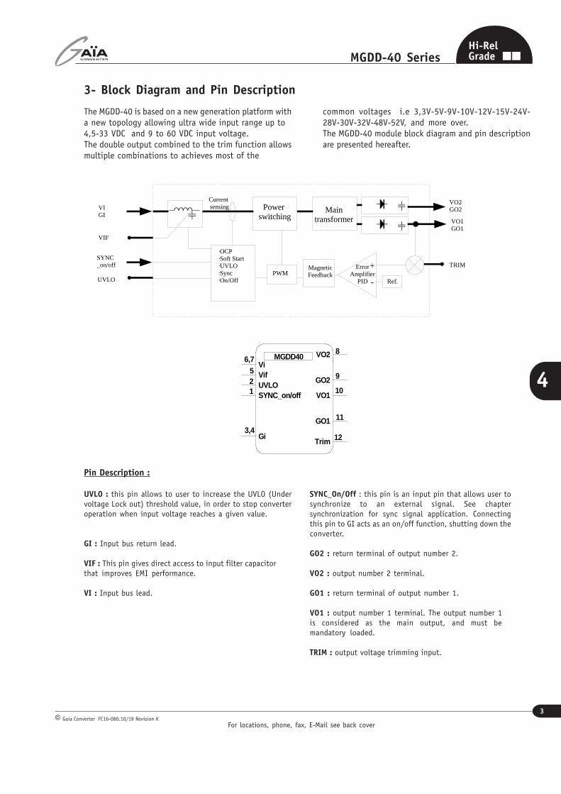
3- Block Diagram and Pin Description
Pin Description :
UVLO : this pin allows to user to increase the UVLO (Undervoltage Lock out) threshold value, in order to stop converteroperation when input voltage reaches a given value.
GI : Input bus return lead.
VIF : This pin gives direct access to input filter capacitorthat improves EMI performance.
VI : Input bus lead.
The MGDD-40 is based on a new generation platform witha new topology allowing ultra wide input range up to4,5-33 VDC and 9 to 60 VDC input voltage.The double output combined to the trim function allowsmultiple combinations to achieves most of the
SYNC_On/Off : this pin is an input pin that allows user tosynchronize to an external signal. See chaptersynchronization for sync signal application. Connectingthis pin to GI acts as an on/off function, shutting down theconverter.
GO2 : return terminal of output number 2.
VO2 : output number 2 terminal.
GO1 : return terminal of output number 1.
VO1 : output number 1 terminal. The output number 1is considered as the main output, and must bemandatory loaded.
TRIM : output voltage trimming input.
8
11
MGDD40
12
6,7
101
52
3,4
9UVLOSYNC_on/off
VifVi
GiTrim
GO2
VO2
GO1
VO1
common voltages i.e 3,3V-5V-9V-10V-12V-15V-24V-28V-30V-32V-48V-52V, and more over.The MGDD-40 module block diagram and pin descriptionare presented hereafter.
Maintransformer
OCPSoft StartUVLOSyncOn/Off
VIF
VO2GO2
VO1GO1
VIGI
Ref.
TRIMMagneticFeedback
+
-
ErrorAmplifier
PIDPWM
SYNC_on/off
UVLO
Power switching
Current sensing
For locations, phone, fax, E-Mail see back cover
4
MGDD-40 Series
Gaia Converter FC16-080.10/19 Revision K©
Hi-RelGrade
4
4
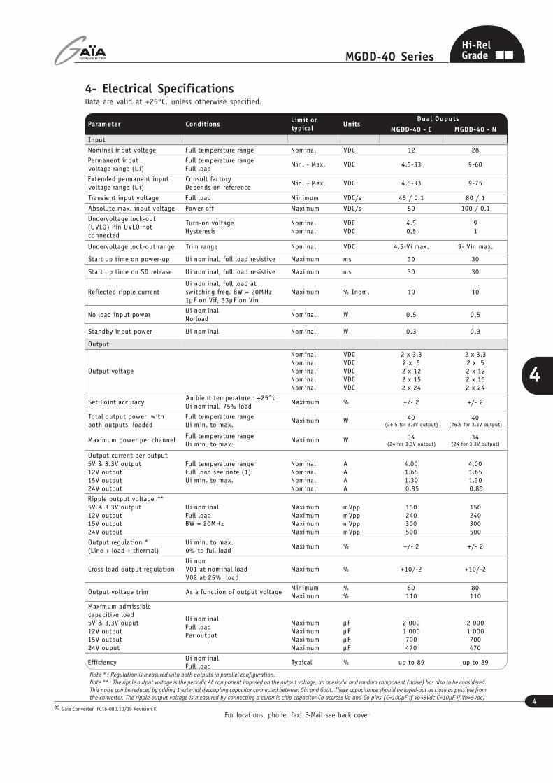
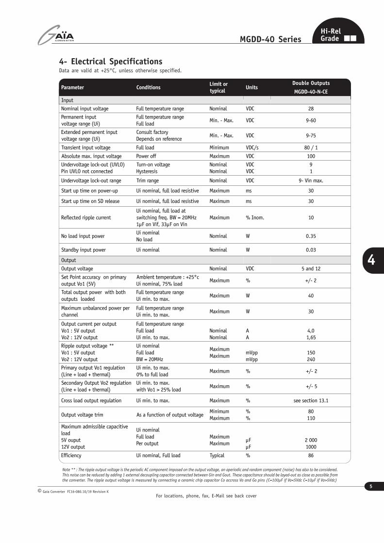
4- Electrical SpecificationsData are valid at +25°C, unless otherwise specified.
Note * : Regulation is measured with both outputs in parallel configuration.
Note ** : The ripple output voltage is the periodic AC component imposed on the output voltage, an aperiodic and random component (noise) has also to be considered.
This noise can be reduced by adding 1 external decoupling capacitor connected between Gin and Gout. These capacitance should be layed-out as close as possible from
the converter. The ripple output voltage is measured by connecting a ceramic chip capacitor Co accross Vo and Go pins (C=100µF if Vo<5Vdc C=10µF if Vo>5Vdc)
Parameter ConditionsLimit ortypical
Units Dual Ouputs
MGDD-40 - E MGDD-40 - N
Input
Nominal input voltage Full temperature range Nominal VDC 12 28
Permanent inputvoltage range (Ui)
Full temperature rangeFull load
Min. - Max. VDC 4.5-33 9-60
Extended permanent inputvoltage range (Ui)
Consult factoryDepends on reference
Min. - Max. VDC 4.5-33 9-75
Transient input voltage Full load Minimum VDC/s 45 / 0.1 80 / 1
Absolute max. input voltage Power off Maximum VDC/s 50 100 / 0.1
Undervoltage lock-out(UVLO) Pin UVLO notconnected
Turn-on voltageHysteresis
NominalNominal
VDCVDC
4.50.5
91
Undervoltage lock-out range Trim range Nominal VDC 4.5-Vi max. 9- Vin max.
Start up time on power-up Ui nominal, full load resistive Maximum ms 30 30
Start up time on SD release Ui nominal, full load resistive Maximum ms 30 30
Reflected ripple currentUi nominal, full load atswitching freq. BW = 20MHz1µF on Vif, 33µF on Vin
Maximum % Inom. 10 10
No load input powerUi nominalNo load
Nominal W 0.5 0.5
Standby input power Ui nominal Nominal W 0.3 0.3
Output
Output voltage
NominalNominalNominalNominalNominal
VDCVDCVDCVDCVDC
2 x 3.32 x 52 x 122 x 152 x 24
2 x 3.32 x 52 x 122 x 152 x 24
Set Point accuracyAmbient temperature : +25°cUi nominal, 75% load
Maximum % +/- 2 +/- 2
Total output power withboth outputs loaded
Full temperature rangeUi min. to max.
Maximum W 40(26.5 for 3.3V output)
40(26.5 for 3.3V output)
Maximum power per channelFull temperature rangeUi min. to max.
Maximum W 34(24 for 3.3V output)
34(24 for 3.3V output)
Output current per output5V & 3.3V output12V output15V output24V output
Full temperature rangeFull load see note (1)Ui min. to max.
NominalNominalNominalNominal
AAAA
4.001.651.30 0.85
4.001.651.30 0.85
Ripple output voltage **5V & 3.3V output12V output15V output24V output
Ui nominalFull loadBW = 20MHz
MaximumMaximumMaximumMaximum
mVppmVppmVppmVpp
150240300500
150240300500
Output regulation *(Line + load + thermal)
Ui min. to max.0% to full load
Maximum % +/- 2 +/- 2
Cross load output regulationUi nomV01 at nominal loadV02 at 25% load
Maximum % +10/-2 +10/-2
Output voltage trim As a function of output voltageMinimumMaximum
%%
80110
80110
Maximum admissiblecapacitive load5V & 3,3V ouput12V output15V output24V ouput
Ui nominalFull loadPer output
MaximumMaximumMaximumMaximum
µFµFµFµF
2 0001 000700470
2 0001 000700470
EfficiencyUi nominalFull load
Typical % up to 89 up to 89
For locations, phone, fax, E-Mail see back cover
5
MGDD-40 Series
Gaia Converter FC16-080.10/19 Revision K©
Hi-RelGrade
4
4
4- Electrical SpecificationsData are valid at +25°C, unless otherwise specified.
Note ** : The ripple output voltage is the periodic AC component imposed on the output voltage, an aperiodic and random component (noise) has also to be considered.
This noise can be reduced by adding 1 external decoupling capacitor connected between Gin and Gout. These capacitance should be layed-out as close as possible fromthe converter. The ripple output voltage is measured by connecting a ceramic chip capacitor Co accross Vo and Go pins (C=100µF if Vo<5Vdc C=10µF if Vo>5Vdc)
Parameter ConditionsLimit ortypical
UnitsDouble Outputs
MGDD-40-N-CE
Input
Nominal input voltage Full temperature range Nominal VDC 28
Permanent inputvoltage range (Ui)
Full temperature rangeFull load
Min. - Max. VDC 9-60
Extended permanent inputvoltage range (Ui)
Consult factoryDepends on reference
Min. - Max. VDC 9-75
Transient input voltage Full load Minimum VDC/s 80 / 1
Absolute max. input voltage Power off Maximum VDC 100
Undervoltage lock-out (UVLO)Pin UVLO not connected
Turn-on voltageHysteresis
NominalNominal
VDCVDC
91
Undervoltage lock-out range Trim range Nominal VDC 9- Vin max.
Start up time on power-up Ui nominal, full load resistive Maximum ms 30
Start up time on SD release Ui nominal, full load resistive Maximum ms 30
Reflected ripple currentUi nominal, full load atswitching freq. BW = 20MHz1µF on Vif, 33µF on Vin
Maximum % Inom. 10
No load input powerUi nominalNo load
Nominal W 0.35
Standby input power Ui nominal Nominal W 0.03
Output
Output voltage Nominal VDC 5 and 12
Set Point accuracy on primaryoutput Vo1 (5V)
Ambient temperature : +25°cUi nominal, 75% load
Maximum % +/- 2
Total output power with bothoutputs loaded
Full temperature rangeUi min. to max.
Maximum W 40
Maximum unbalanced power perchannel
Full temperature rangeUi min. to max.
Maximum W 30
Output current per outputVo1 : 5V outputVo2 : 12V output
Full temperature rangeFull loadUi min. to max.
NominalNominal
AA
4,01,65
Ripple output voltage **Vo1 : 5V outputVo2 : 12V output
Ui nominalFull loadBW = 20MHz
MaximumMaximum
mVppmVpp
150240
Primary output Vo1 regulation(Line + load + thermal)
Ui min. to max.0% to full load
Maximum % +/- 2
Secondary Output Vo2 regulation(Line + load + thermal)
Ui min. to max.with Vo1 > 25% load
Maximum % +/- 5
Cross load output regulation Ui min. to max. Maximum % see section 13.1
Output voltage trim As a function of output voltageMinimumMaximum
%%
80110
Maximum admissible capacitiveload5V ouput12V output
Ui nominalFull loadPer output
MaximumMaximum
µFµF
2 0001000
Efficiency Ui nominal, Full load Typical % 86

For locations, phone, fax, E-Mail see back cover
6
MGDD-40 Series
Gaia Converter FC16-080.10/19 Revision K©
Hi-RelGrade
4
4
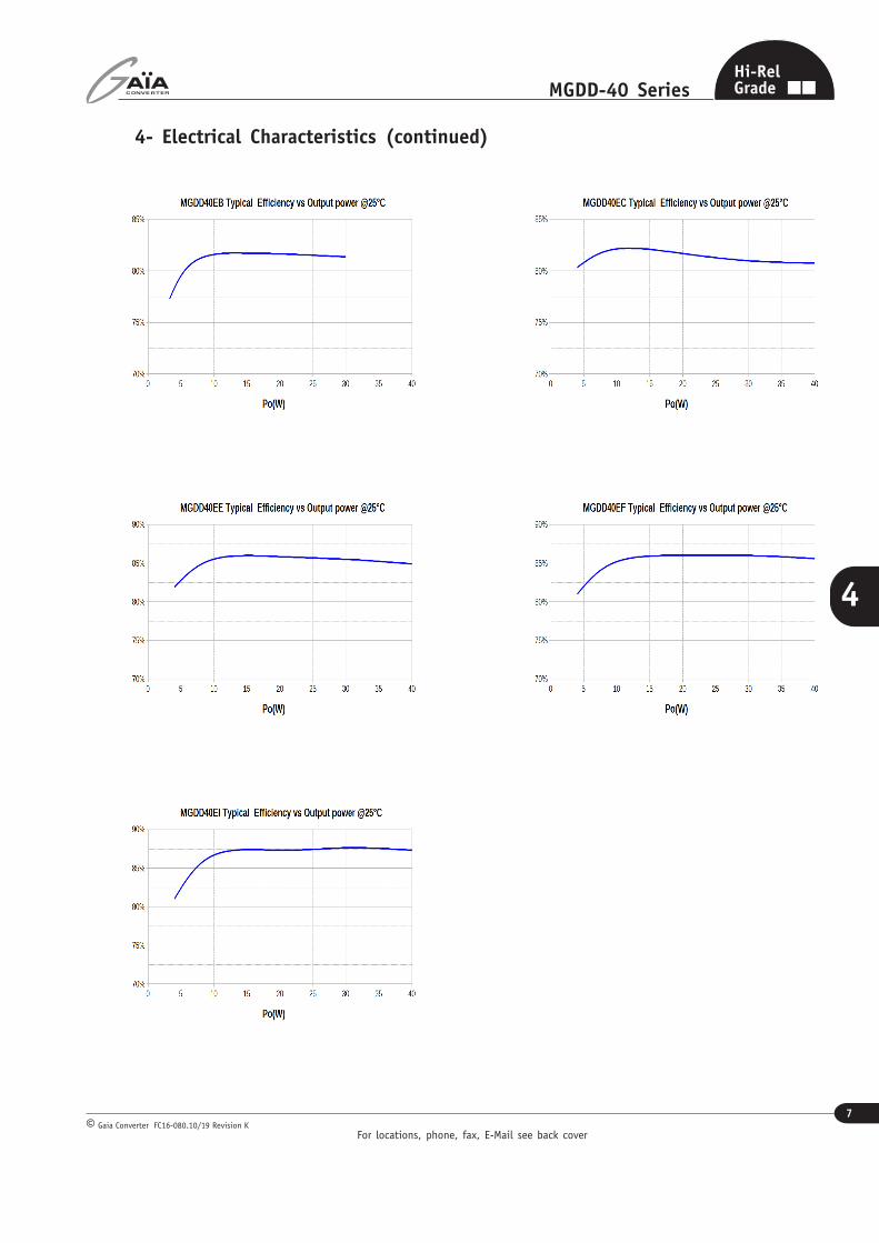
4- Electrical Characteristics (continued)
For locations, phone, fax, E-Mail see back cover
7
MGDD-40 Series
Gaia Converter FC16-080.10/19 Revision K©
Hi-RelGrade
4
4
4- Electrical Characteristics (continued)

For locations, phone, fax, E-Mail see back cover
8
MGDD-40 Series
Gaia Converter FC16-080.10/19 Revision K©
Hi-RelGrade
4
4
5- Switching Frequency
7- Protection Functions
Characteristics Protection Device Recovery Limit or typical Specifications
Input undervoltage lock-out (UVLO)Turn-on, turn-off circuitwith hysteresis cycle
Automaticrecovery
Turn-on nominalTurn-off nominal
See section 3
Output current limitation protection (OCP)Straight line currentlimitation
Automaticrecovery
TypicalMinimum
160% of Inom.105% of Inom.
8- Reliability Data
Characteristics Conditions Limit or typical Specification
Switching frequencyFull temperature rangeUi min. to max.No load to full load
Nominal, fixed 330 KHz
Synchronization frequency rangeFrequency of externalsynchronization signal
MinimumMaximum
270 KHz360 KHz
6- Isolation
Characteristics Conditions Temperature Specifications
Mean Time Between Failure (MTBF)According to MIL-HDBK-217F
Ground benign (Gb) Case at 40°C 2 855 000 Hrs
Ground fixed (Gf)Case at 40°CCase at 70°C
1 025 000 Hrs470 000 Hrs
Airborne, InhabitedCargo (AIC)
Case at 40°CCase at 70°C
595 000 Hrs295 000 Hrs
Mean Time Between Failure (MTBF)According to IEC-62380-TR
Aircraft CivilianAmbient at 25°C100% time on
Consult factory
Parameters Conditions Limit or typical Specifications
Isolation voltage(Case not connected)
Input to outputBetween outputs
MinimumMinimum
1 500 Vdc/ 1 min300 Vdc
Isolation safety ratingInput to outputBetween outputs
/ Functionnal
Isolation capacitance Input to input Typical 1 nF
Isolation resistanceInput to case 500 VdcOutput to case 500 Vdc
MinimumMinimum
100 MOhm100 MOhm

For locations, phone, fax, E-Mail see back cover
9
MGDD-40 Series
Gaia Converter FC16-080.10/19 Revision K©
Hi-RelGrade
4
49-1 Module Compliance with MIL-STD-461C/D/E/F Standards
To meet the latest US military standards MIL-STD-461 requirements and in particular the conducted noise emission CE102(and also CE03) requirements, Gaïa Converter can propose an EMI filter module. In addition common mode capacitancesC
mc (10nF/rated voltage depending on isolation requirement) connected between power pins and chassis or ground power-
plane need to be implemented. When output channels are intended to be connected to load through long wire, it could benecessary to use additionnaly common mode inductors on each outputs. For a use at 28Vdc C7 can be rated to 47µF.
Please consult FGDS-series datasheets for further details.
9- Electromagnetic Interference and Surge
Electromagnetic Interference requirements according to MIL-STD-461C/D/E/F standards can be easily achieved as indicatedin the following section. The following table resumes the different sections covered by these standards.
Standard RequirementsMIL-STD-461C
StandardMIL-STD-461D/E/F
Standard
Compliance with GAIA ConverterModule & common mode
capacitance
Conducted emission (CE) :Low frequencyHigh frequency
CE 01CE 03
CE 101CE 102
compliant module stand-alonecompliant with additionnal filter
Conducted susceptibility (CS) :Low frequencyHigh frequency
CS 01CS 02
CS 101CS114
compliant with additionnal filtercompliant with additionnal filter
Radiated emission (RE) :Magnetic fieldElectrical field
RE 01RE 02
RE 101RE 102
compliant module stand-alonecompliant module stand-alone
Radiated susceptibility (RS) :Magnetic fieldElectrical field
RS 01RS 03
RS 101RS 103
compliant module stand-alonecompliant module stand-alone

For locations, phone, fax, E-Mail see back cover
10
MGDD-40 Series
Gaia Converter FC16-080.10/19 Revision K©
Hi-RelGrade
4
4
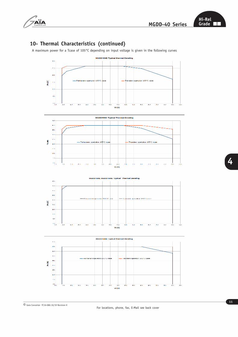
10- Thermal Characteristics
To calculate the maximum ambient temperature at which the converter will be able to operate, the following parametersare required :
- Tcase = maximum case temperature the converter can operate- Tmax = maximum ambient temperature the converter can operate- Pout = effective output power used (see also page therafter curves of maximum power)- Rth(c) = thermal resistance case to ambient of the converter (see table below) in free air natural convection- Rth(tot) = thermal resistance of converter and its heatsink (if used)- Rth(hs) = Thermal resistance of heat sink (if used)- η = converter efficiency
There are 3 mounting possibilities as described below :
Converter with Heatsink Mounting
To calculate the maximum ambient temperature theconverter can operate, the following formula can beapplied :
Tmax = Tcase - Rth(tot) x Pout(1/ηηηηη – 1)
The most sensitive parameter in this formula is theRth(tot) value.Rth(tot) depends on the thermal resistance of theconverter Rth(c) in the mounting configuration and thethermal resistance of the heatsink Rth(hs). - The Rth(c) depends on ambient temperature, the way the converter is tied to the PCB, position,PCB copper track and power plane length. Also, in general Rth(c) decreases as temperature is increases. - Rth(hs) : Rth(hs) value is highly depending on how the heatsink is connected to case.
The value of Rth(tot) can be evaluated with the belowdefinition :Rth(c)*Rth(hs)/(Rth(c)+Rth(hs)) < Rth(tot) < Rth(c)
The table hereafter gives some example of thermal resistance for different heat transfert configurations.
Heat transfertThermal resistanceheatsink to air Rth(h-a)
Conditions Globalresistance
Free air coolingonly
Rth(c) : no Heatsink baseplate only Ambient 60°C, converter on PCB 13.2
Rth(tot) with heatsink ABL BGA-STD-110(30 mm x 30 mm)
Ambient 60°C, converter on PCB < 8.5
mbient 60°C
Characteristics Conditions Limit or typical Performances
Operating ambient temperaturerange
Ambient temperatureMinimumMaximum
- 40°Csee below
Operating case temperaturerange
Case temperatureMinimumMaximum
- 40°C105°C
Storage temperature range Non functionningMinimumMaximum
- 55°C+ 125°C
Converter Stand-Alone Mounting
To calculate the maximum ambient temperature atwhich the converter can operate, the followingformula can be applied :
Tmax = Tcase - Rth(c) x Pout(1/ηηηηη – 1)
Converter with Chassis Mounting
If the thermal interface resistance can be neglected,the maximum chassis temperature is equal to themaximum converter case temperature.
Tmax chassis = Tmax.
MGDD40
MGDD40
Heat sink
Thermal interface
spacer
Bolt srewed on heat sink
MGDD40
Chassis
Thermal interface
For locations, phone, fax, E-Mail see back cover
11
MGDD-40 Series
Gaia Converter FC16-080.10/19 Revision K©
Hi-RelGrade
4
4
10- Thermal Characteristics (continued)A maximum power for a Tcase of 105°C depending on input voltage is given in the following curves
For locations, phone, fax, E-Mail see back cover
12
MGDD-40 Series
Gaia Converter FC16-080.10/19 Revision K©
Hi-RelGrade
4
4
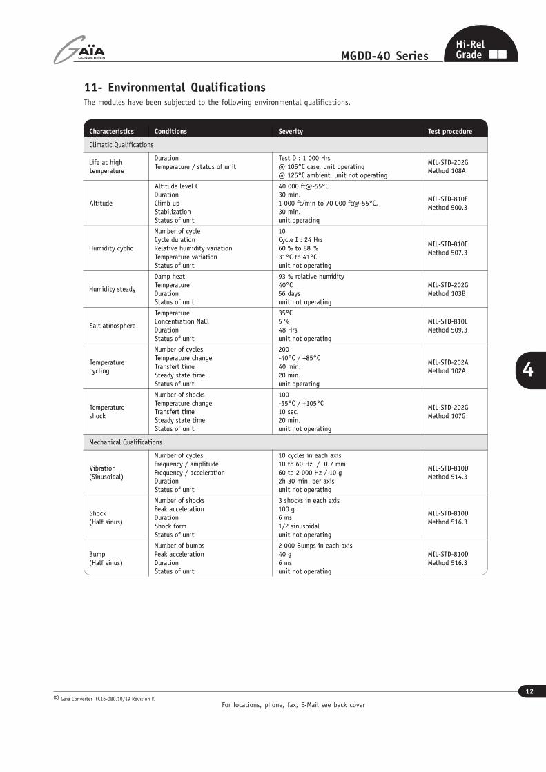
11- Environmental QualificationsThe modules have been subjected to the following environmental qualifications.
Characteristics Conditions Severity Test procedure
Climatic Qualifications
Life at hightemperature
DurationTemperature / status of unit
Test D : 1 000 Hrs@ 105°C case, unit operating@ 125°C ambient, unit not operating
MIL-STD-202GMethod 108A
Altitude
Altitude level CDurationClimb upStabilizationStatus of unit
40 000 ft@-55°C30 min.1 000 ft/min to 70 000 ft@-55°C,30 min.unit operating
MIL-STD-810EMethod 500.3
Humidity cyclic
Number of cycleCycle durationRelative humidity variationTemperature variationStatus of unit
10Cycle I : 24 Hrs60 % to 88 %31°C to 41°Cunit not operating
MIL-STD-810EMethod 507.3
Humidity steady
Damp heatTemperatureDurationStatus of unit
93 % relative humidity40°C56 daysunit not operating
MIL-STD-202GMethod 103B
Salt atmosphere
TemperatureConcentration NaClDurationStatus of unit
35°C5 %48 Hrsunit not operating
MIL-STD-810EMethod 509.3
Temperaturecycling
Number of cyclesTemperature changeTransfert timeSteady state timeStatus of unit
200-40°C / +85°C40 min.20 min.unit operating
MIL-STD-202AMethod 102A
Temperatureshock
Number of shocksTemperature changeTransfert timeSteady state timeStatus of unit
100-55°C / +105°C10 sec.20 min.unit not operating
MIL-STD-202GMethod 107G
Mechanical Qualifications
Vibration(Sinusoidal)
Number of cyclesFrequency / amplitudeFrequency / accelerationDurationStatus of unit
10 cycles in each axis10 to 60 Hz / 0.7 mm60 to 2 000 Hz / 10 g2h 30 min. per axisunit not operating
MIL-STD-810DMethod 514.3
Shock(Half sinus)
Number of shocksPeak accelerationDurationShock formStatus of unit
3 shocks in each axis100 g6 ms1/2 sinusoidalunit not operating
MIL-STD-810DMethod 516.3
Bump(Half sinus)
Number of bumpsPeak accelerationDurationStatus of unit
2 000 Bumps in each axis40 g6 msunit not operating
MIL-STD-810DMethod 516.3
For locations, phone, fax, E-Mail see back cover
13
MGDD-40 Series
Gaia Converter FC16-080.10/19 Revision K©
Hi-RelGrade
4
4
12- Description of Protections
The MGDD-40 series includes 2 types of protection devices.
12-1 Input Undervoltage Lockout (UVLO)
An input undervoltage protection will inhibit the module when inputvoltage drops below the lock-out turn-off threshold (see section 3for value) and restores to normal operation automatically when theinput voltage rises above the lock-out turn-on threshold.
The UVLO voltage can be adjusted using an external resistor (Ruvlo)connected between pin 2 and Gi. This value can be adjusted in orderto allow converter to shut down properly depending on the inputbus (or battery) voltage value. Ruvlo can be determined using thefollowing formula
Ruvlo (KΩ) = A - 1 Vuvlo - BRuvlo = trimming resistanceVuvlo = desired turn-on voltageA & B = input range parameter (see table below)
Values are in KOhms
12-2 Output Over Current Protection (OCP)
The MGDD-40 Series incorporates an over-current protectioncircuit that detects short circuit or over current and protectsthe module according to the hiccup graph .The maximum detection current Id is depending on input voltageVin and temperature. When OCP is triggered, the converter fallsinto hiccup mode, testing periodically if the overload is stillpresent. The module restart automatically in soft-start to normaloperation when overcurrent is removed. Td (detection time) and Th
(hiccup period)are depending on Vin and temperature.
On
Off
Vin
UVLO Turn- on
UVLO Turn- off
UVLO Turn- on
UVLO Turn- off
UVLO trimmed
Converter Series Parameter A Parameter B
MGDD-40-N Series 110 8.51
MGDD-40-E Series 41 3.69
For locations, phone, fax, E-Mail see back cover
14
MGDD-40 Series
Gaia Converter FC16-080.10/19 Revision K©
Hi-RelGrade
4
4
13-1-1 Connection of Outputs in SeriesOutputs connected in series allow to achieve 6,6V, 10V,24V, 30V or 48V output voltages up to 40W total power.These values can be extended using trim adjustment.
13-1-3 Connection of Outputs in SymmetryOutputs connected in symmetry allow to achieve +/-5V,+/-12V, +/-15V or +/-24V voltages (+/-20W on each channel)with possible unbalanced loadup to 34W on output 1,6W on output 2 and vice versa.
13- Description of Functions13-1 Connection of OutputsThe outputs of MGDD-40 can be connected in various configurations such as :
- connections in series- connection in parallel (not applicable for MGDD-40-NCE)- connection in symmetry- connection in independance
Please note that regulation is achieved through output VO1/GO1 referenced as primary output. When connected in symmetryor independant configurations with unbalanced loads, VO1/GO1 has to be loaded at 4W minimum to insure proper operationof the converter.
Outputs connected independantly with floating voltagebetween each other can be achieved for 2x3,3V, 2x5V,2x12V, 2x15V or 2x24V voltages (20W each) with possi-ble unbalanced load up to 34W on output 1, 6W onoutput 2 and vice versa.
13-1-2 Connection of Outputs in ParallelOutputs connected in parallel allow to achieve single output3,3V, 5V, 12V, 15V or 24V up to 40W power. These values canbe extended using trim adjustment.
13-1-4 Connection of Outputs in Independance
0% 20% 40% 60% 80% 100% 120% 140% 160% 180% 200%80%
85%
90%
95%
100%
105%
110%
115%
120%
125%
130%
MGDD40N TYPICAL CROSS-REGULATION @ 25°C
Vo1 (% of Vo1 nom.)
Vo2 for Io1 =20% of Io1 nom.
Vo2 for Io1 =50% of Io1 nom.
Vo2 for Io1 =100% of Io1 nom.
Io2 (% of Io2 nom.)
Vo
(%
of
Vo
no
m.)
VO2/GO2 limits :The VO2/GO2 outputreferenced as secondaryoutput may stay unloadedbut in that case itsregulation may drift-up.VO2 drift increases withVO1 load and can reachup to 130% (typical) ofVO2 nominal voltage inworst case. A 10% loadon VO2 will bring backthe drift within lower va-lues as per graph.
Vo2 regulation versus current Io2 as % of nominal Io2nom@ Vo1 various fixed load as a % of nominal current Io1nom
For locations, phone, fax, E-Mail see back cover
15
MGDD-40 Series
Gaia Converter FC16-080.10/19 Revision K©
Hi-RelGrade
4
4
13- Description of Functions (continued)
13-2 Trim Function
The output voltage Vo1 may be trimmed in a range of80% to 110% of the nominal output voltage (100%/110% for 3,3Vdc output voltage) via a single external trimpot or fixed resistor.
The VO2 output will be automatically trimmed to the same value asV02, whatever the outputs combination is.
Trim Up Function
Do not attempt to trim the module higher than 110% of nomi-nal output voltage as the overvoltage protection may trigger.
Also do not exceed the maximum rated output power when themodule is trimmed up.
The trim up resistance must be calculated with the followingformula :
Ru is the trim resistor value in KOhmVO
nom is the nominal output voltage 1
VO is the desired trimmed output voltage
Trim Down Function
Do not trim down more than -20% of nominal output voltageotherwise the module may be damaged.
The available output power is reduced by the same percentagethat the output voltage is trimmed down.
The trim down resistance must be calculated with the followingformula :
Rd is the trim resistor value in KOhmVO
nom is the nominal output voltage 1
VO is the desired trimmed output voltage
For locations, phone, fax, E-Mail see back cover
16
MGDD-40 Series
Gaia Converter FC16-080.10/19 Revision K©
Hi-RelGrade
4
4
13- Description of Functions (continued)
13-3 On/Off (SYNC_On/Off) Function
The control pin 1 (SYNC_On/Off) can be used for applicationsrequiring On/Off operation. This may be done with an opencollector transistor, a switch, a relay or an optocoupler. Severalconverters may be disabled with a single switch by connectingall SYNC_On/Off pins together.
• The converter is disabled by pulling low pin 1.• No connection or high impedance on pin 1 enables theconverter.
By releasing the On/Off function, the converter will restartwithin the start up time specifications given in table section 3
Parameter Unit Min. Typ. Max. Notes, conditions
On/Off module enable voltage Vdc 2.5 / 3.3 Open, the switch must not sink more than 50µA
On/Off module disable voltage Vdc 0 / 0.5 The switch must be able to sink 0,5mA
On/Off module enable delay ms / / 30 The module restarts with the same delay after alarm mode removed
On/Off module disable delay µs / / 100 Vi nominal, full load
13-4 Synchronization (SYNC_On/Off) FunctionThe MGDD-40 voltage series provides an externalsynchronization function through the SYNC-On/Off pin.SYNC-On/Off pin is an input only and is referenced to Gi.Automatic synchronization of multiple units (all Sync pinsconnected) is not possible.This pin can be driven directly by using a LV TTL (3,3V) gate.SYNC_On/Off pin is internally pulled up to 3V (logic level 1). Itis possible to synchronize the module by using totem polestage (transistor, optocoupler, …). Minimum 3,3V LV TTL risetime (tr) and fall time (tf) are 20ns. The module can lock onfrequency above or below its free-run frequency2.52 µs < Tsync < 3.78µs and 0.3 µs<Tp< 2.7µs.
13-5 Input Filter Compensation (VIF)The «VIF» pin is a direct access to the capacitor of theinternal LC input filter. For stringent application it is possibleto improve the converter stability and to reduce the inputcurrent ripple for better EMI performance, by adding acapacitor accross “VIF” pin and “Gin” pin.This capacitor should have the proper voltage ratingcompatible with the input range. Because of high currentflowing through it, it should be of ceramic type and connectedbetween “VIF” and “Gin” as close as possible.
For locations, phone, fax, E-Mail see back cover
17
MGDD-40 Series
Gaia Converter FC16-080.10/19 Revision K©
Hi-RelGrade
4
4
14- Dimensions
17- Connections
Pin Dual
1 Sync-SD
2 UVLO
3 - Input (Gi)
4 - Input (Gi)
5 VIF
6 + Input (Vi)
7 + Input (Vi)
8 + Output 2 (Vo2)
9 - Output 2 (Go2)
10 + Output 1 (Vo1)
11 - Output 1 (Go1)
12 Vtrim
Bottom view
Dimension are given in mm. Tolerance : +/- 0,2 mm (+/- 0.01 “) unless otherwise indicated.All dimensions specified ‘’Min’’ or ‘’Max’’ are subjected to tolerance Min+0,5/-0mm and Max+0/-0,5mm.Weight : 40 grams ( 0,7 Ozs) max.
The MGDD-40 series has been designed for on-board mounting.it is recommended not to lay-out any component under the module.
15- Materials
Case : Metallic black anodized coating.Pins : Flash gold plating over nickel underplate.
16- Product Marking
Upper face : Company logo.Side face : Module reference, option, date code : year and week of manufacturing.
Information given in this datasheet is believed to be accurate and reliable. However, no responsibility is assumed for the consequence of its use nor for any infringement of patents or other rights of third parties which may result from its use.These products are sold only according to GAIA Converter general conditions of sale, unless otherwise confirmed by writing. Specifications subject to change without notice.
Prin
ted
in F
ranc
e by
GAIA
Con
vert
er G
aia
Conv
erte
r F
C16-
080.
10/1
9 Re
visi
on K
. Gr
aphi
sme
: Ph
ilipp
e Cl
icq
Represented by :
For more detailed specifications and applications information, contact :
International HeadquartersGAÏA Converter - France
ZI de la Morandière33185 LE HAILLAN - FRANCETel. : + (33)-5-57-92-12-80Fax : + (33)-5-57-92-12-89
North American HeadquartersGAÏA Converter Canada, Inc4038 Le Corbusier BlvdLAVAL, QUEBEC - CANADA H7L 5R2Tel. : (514)-333-3169Fax : (514)-333-4519