hid6506 rotary impact drill
TRANSCRIPT
HID6506 Rotary Impact Drill
SERVICE MANUAL
Serial Codes AML and GAT
Read and understand all of the instructions and safety information in this manual before operating or servicing this tool.
Register this product at www.greenlee.com
AML
GAT
99915979 REV 8 © 2019 Greenlee Tools, Inc. 10/19
HID6506 Rotary Impact Drill
Greenlee Tools, Inc. 4455 Boeing Dr. • Rockford, IL 61109-2988 USA • 815-397-70702
Table of Contents
Safety ............................................................................ 2
Purpose of this Manual ................................................. 2
Other Publications ......................................................... 2
Important Safety Information .....................................3–4
Disassembly ...............................................................5–6
Inspection ...................................................................... 7
Assembly ....................................................................7–9
Illustrations and Parts Lists ....................................10–15
Safety
Safety is essential in the use and maintenance of Greenlee tools and equipment. This service manual and any markings on the tool provide information for avoid-ing hazards and unsafe practices related to the use of this tool. Observe all of the safety information provided.
KEEP THIS MANUAL
Purpose of this Manual
This manual is intended to familiarize personnel with the safe service procedures for the following Greenlee tools:
HID6506 (42309) Rotary Impact Drill Serial Codes AML and GAT
Keep this manual available to all personnel.
Replacement manuals are available upon request at no charge at www.greenlee.com.
Other Publications
Operation Manual: Publication 99940116
SAE Standard J1273 (Hose and Hose Assemblies): Publication 99930323
All specifications are nominal and may change as design improvements occur. Greenlee Tools, Inc. shall not be liable for damages resulting from misapplication or misuse of its products.
Super Spool is a trademark of Greenlee Tools, Inc.
Loctite is a registered trademark of Henkel Corporation.

HID6506 Rotary Impact Drill
Greenlee Tools, Inc. 4455 Boeing Dr. • Rockford, IL 61109-2988 USA • 815-397-70703
IMPORTANT SAFETY INFORMATION
SAFETY ALERT SYMBOL
This symbol is used to call your attention to hazards or unsafe practices which could result in an injury or property damage. The signal word, defined below, indicates the severity of the hazard. The message after the signal word provides information for preventing or avoiding the hazard.
Immediate hazards which, if not avoided, WILL result in severe injury or death.
Hazards which, if not avoided, COULD result in severe injury or death.
Hazards or unsafe practices which, if not avoided, MAY result in injury or property damage.
Read and understand all of the instructions and safety information in this manual before operating or servicing this tool. Refer also to the Operation manual, which is listed under “Other Publications.”
Failure to observe this warning could result in severe injury or death.
Skin injection hazard:
• Do not use hands to check for leaks.
• Do not hold hose or couplers while the hydraulic system is pressurized.
• Depressurize the hydraulic system before servicing.
Oil under pressure easily punctures skin causing serious injury, gangrene or death. If you are injured by escap-ing oil, seek medical attention immediately.
Wear eye protection when operating or servicing this tool.
Failure to wear eye protection could result in serious eye injury from flying debris or hydraulic oil.
Tool, accessory, and other components may be hot during and after operation. Allow to cool before handling, or handle with heat-resistant gloves.
Failure to observe this warning could result in severe injury.

HID6506 Rotary Impact Drill
Greenlee Tools, Inc. 4455 Boeing Dr. • Rockford, IL 61109-2988 USA • 815-397-70704
IMPORTANT SAFETY INFORMATION
Do not exceed the following hydraulic power source maximums:
• Hydraulic flow: 45.4 l/min (12 gpm)
• Pressure relief: 138 bar (2000 psi)
• Back pressure: 13.8 bar (200 psi)
Failure to observe this warning could result in severe injury or death.
Do not disconnect tool, hoses, or fittings while the power source is running or if the hydraulic fluid is hot. Hot hydraulic fluid can cause serious burns.
Do not reverse hydraulic flow. Operation with hydraulic flow reversed can cause tool malfunction. Connect the pressure (supply) hose and tank (return) hose to the proper ports.
Failure to observe this warning could result in severe injury or death.
Hydraulic oil can cause skin irritation.
• Handle the tool and hoses with care to prevent skin contact with hydraulic oil.
• In case of accidental skin contact with hydraulic oil, wash the affected area immediately to remove the oil.
Failure to observe these precautions may result in injury.
Notes: Keep all decals clean and legible. Replace when necessary.
When disposing of any components (hydraulic hoses, hydraulic fluid, worn parts, etc.), do so in accordance with federal, state and local laws or ordinances.

HID6506 Rotary Impact Drill
Greenlee Tools, Inc. 4455 Boeing Dr. • Rockford, IL 61109-2988 USA • 815-397-70705
Disassembly
Complete disassembly of the tool is not recommended. If a complete overhaul is necessary, return the tool to your nearest Greenlee Authorized Service Center.
The disassembly procedure is divided into sections of the tool. Disassemble only the section(s) necessary to complete the repair.
Disassemble the tool on a flat, clean surface. Take care not to lose or damage any parts that may fall free during disassembly.
Rotary Impact Mechanism
1. Remove three cap screws (63). Remove the rotary impact mechanism (62).
2. Remove the rubber seal (60) and felt seal (61).
Note: Greenlee does not recommend complete disassembly of the mechanism. If required, replace mechanism as an assembly (52058181).
Adapter and Drive Shaft
1. Remove four cap screws (65), adapter (57), and gasket (64).
2. Remove the retaining ring (58) from the adapter (57). Push the drive shaft (55) and bearing (56) out of the adapter (57).
3. If necessary, remove the shaft seal (59), gear (54), and bearings (56) from the drive shaft (55).
Motor
1. Scribe a line across the motor cap (47) and handle (1) to align parts correctly during assembly.
2. Remove eight cap screws (49) and pull the motor cap from the handle. Remove the gasket (46). If necessary, remove the dowel pins (45).
3. Pull the idler shaft (43) and gear (40) from the handle. Remove the gear from the idler shaft. If necessary, remove the drive pin (44) from the idler shaft.
4. Remove the retaining clip (42), gear (40), and Woodruff key (41) from the gear carrier shaft (53). Pull the gear carrier shaft (53) from the trigger side of the handle (1).
5. If the gear carrier shaft components require disassembly, drive two dowel pins (52) from the gear carrier shaft (53) using a punch. Pull two small gears (51) from the gear carrier shaft (53).
6. Remove the ring gear (4) and roll pin (5) from the handle, if necessary.
7. Use an O-ring tool to remove the O-ring (2) without removing the needle bearing (3).
Needle Bearing Removal
Note: If the needle bearings (3, 48) in the motor cap (47) or handle (1) are damaged or worn, Greenlee recom-mends replacing the component as an assembly with bearings already pressed in.
1. Do not remove the needle bearings (3, 48) unless they are damaged or worn. Bearings will be ruined when they are removed.
2. A blind-hole bearing puller is required to remove needle bearings from the motor cap (47) or handle (1).

HID6506 Rotary Impact Drill
Greenlee Tools, Inc. 4455 Boeing Dr. • Rockford, IL 61109-2988 USA • 815-397-70706
Trigger, Control Spool, and Super Spool™ Sleeve
1. Remove the retaining ring (25) and cap (24) from the sleeve (19). Remove the compression spring (29) from the end of the control spool (26).
2. Remove the connecting link (33) from the trigger (32) and control spool (26). Remove one machine screw (34) and nut (35) from the trigger (32). Remove the trigger.
3. Remove the retaining ring (31) and washer (30). Remove the control spool (26) from the sleeve (19). Remove the O-ring (27) from the control spool (26).
4. Remove the retaining ring (22) from the sleeve (19). Remove the sleeve from the handle (1).
5. Remove the O-rings (20, 21, 23) from the sleeve (19). Remove the O-ring (18) from the handle (1).
Directional Spool
1. Remove both cap screws (17) and buttons (16) from the directional spool (14). Slide the directional spool part way through the bore to expose one O-ring (15). Remove the exposed O-ring.
2. Remove the directional spool (14) by pushing it back through the bore. Remove the remaining O-ring (15).
Note: Attempting to force the directional spool through the bore against the O-ring will damage the O-ring and could allow particles of O-ring to get into the motor.
Flow Control Cartridge
1. Remove the retaining ring (9). Pull the flow control cartridge (6) out of the handle.
2. Remove the O-rings (7, 8).
Do not attempt to repair the flow control cartridge. It contains no replaceable parts.
Failure to observe this warning could result in severe injury or death.
Adjustable Torque Output Screw
1. Remove the spring pin (13) from the handle.
2. Turn the torque output screw (10) counterclockwise until the threads disengage, and remove it from the handle.
3. Remove the O-ring (11) and back-up ring (12).
Disassembly (cont’d)

HID6506 Rotary Impact Drill
Greenlee Tools, Inc. 4455 Boeing Dr. • Rockford, IL 61109-2988 USA • 815-397-70707
Inspection
Clean all parts with an appropriate cleaning solution and dry them thoroughly. Inspect each component as described in this section. Replace any component that shows wear or damage.
1. Rotary Impact Assembly: Inspect the exterior for damage and loose or missing parts. Inspect the spur gear (through the small view hole in the end of the mechanism) for grooves, nicks and chips. If the unit is damaged, replace the impact assembly.
2. Bearings: Insert shaft into bearings. Spin shaft. If the shaft does not spin smoothly, replace the entire assembly with bearings already pressed in.
3. Motor Cap, Handle, and Adapter: Inspect mating surfaces, bores, oil passageways, etc. for grooves or nicks. If any component shows wear or damage, replace the entire assembly with bearings already pressed in.
4. Planet Gear with Needle Bearings: Insert a corre-sponding dowel pin into the bearing. While holding the dowel between a thumb and forefinger, roll the gear in the palm of your other hand. If either gear does not spin smoothly, replace both gears with bearings already pressed in.
5. Inspect all other disassembled components for cracks, grooves or nicks.
Assembly
Refer to the Illustrations and Parts Lists for correct orientation and placement of parts.
Replace any O-rings, V-rings, seals, and gaskets on parts that have been disassembled. Apply hydraulic fluid or O-ring lubricant to all O-rings and all metal surfaces which they must slide over. When installing an O-ring which must slide over sharp surfaces, use a rolling motion and be careful not to damage the O-ring.
Wherever the assembly results in metal-to-metal contact, coat the surfaces with hydraulic fluid or O-ring lubricant.
Some steps of the assembly procedure require a remov-able type of thread sealing and locking compound, such as Loctite® 242 or equivalent. Follow the manufacturer’s instructions for curing.
Needle Bearing Installation in Handle or Motor Cap
HANDLE:
1. Install a new needle bearing (3) with identification mark facing up (readable from Surface A) into the handle (1).
2. Press the bearing into the handle until the bearing cage is 0.020 inch below Surface A.
3. Repeat the procedure for the other needle bearing if it was removed.
MOTOR CAP:
1. Install a new needle bearing (48) with identification mark facing up (readable from Surface B) into the motor cap (47).
2. Press the bearing into the motor cap until the bearing cage is 0.047 inch below Surface B.
3. Repeat the procedure for the other needle bearing if it was removed.
Needle Bearing Installation in Handle and Motor Cap
Surface B
Motor Cap
Surface A
Motor Body
O-ring Seal
Needle Bearing
0.020 belowSurface A
0.047 belowSurface B

HID6506 Rotary Impact Drill
Greenlee Tools, Inc. 4455 Boeing Dr. • Rockford, IL 61109-2988 USA • 815-397-70708
Assembly (cont’d)
Motor
1. Install the ring gear (4) into the handle (1), align-ing the notch in the ring gear with the notch in the handle. Insert the roll pin (5) into the hole that is formed when these two components are aligned correctly. The roll pin (5) must be flush or below the handle surface.
2. Install a new O-ring (2) in the drive shaft opening (1) using an O-ring tool. Be careful not to damage the O-ring during installation. Install the gear carrier shaft (53) into the handle.
3. Install the Woodruff key (41) in the gear carrier shaft (53). Slide one gear (40) onto the gear carrier shaft (53), guiding the keyway in the gear (40) over the Woodruff key (41). Secure the gear to the drive shaft with the retaining clip (42).
4. Install the drive pin (44) into the idler shaft (43), if removed. Slide the remaining gear (40) onto the idler shaft, guiding the keyway in the gear over the drive pin. Install the idler shaft and gear in the handle (1), meshing the two gears (40) together.
5. Install two dowel pins (45) in the handle (1), if removed. Install a new gasket (46).
6. Install the motor cap (47) on the handle (1), aligning the scribe marks that were made during disassembly.
7. Secure the motor cap (47) to the handle (1) using eight cap screws (49). Using the sequence shown below, torque to 9 newton-meters (80 inch-pounds).
Torque Sequence
1
3
4
2
5 7
8 6
Directional Spool
1. Slide the directional spool (14) in the handle (1).
2. Install one O-ring (15) on the directional spool. Slide the spool through the handle just far enough to install the remaining O-ring (15) on the spool.
3. Apply a thread-locking compound to the threads of the cap screws (17). Secure the buttons (16) to the directional spool with the cap screws. Torque to 3.4 to 3.9 newton-meters (30 to 35 inch-pounds).
Trigger, Control Spool, and Super Spool Sleeve
1. Install the O-ring (18) in the sleeve cavity of the handle (1). Install the O-rings (20, 21, 23) on the sleeve (19).
2. Install the sleeve (19) in the handle (1). Secure the sleeve in the handle with the retaining ring (22).
3. Install the spring (29), washer (24), and retaining ring (25) into the sleeve (19). Install the O-ring (27) onto the control spool.
4. Slide the control spool (26) in the sleeve (19) from the trigger side of the handle (1). Install the washer (30) in the end of the sleeve. Secure the washer to the sleeve with the retaining ring (31).
5. Secure the trigger (32) to the handle (1) with the machine screw (34) and stop nut (35).
6. Attach the connecting link (33) to the trigger (32) and control spool (26).
HID6506 Rotary Impact Drill
Greenlee Tools, Inc. 4455 Boeing Dr. • Rockford, IL 61109-2988 USA • 815-397-70709
Assembly (cont’d)
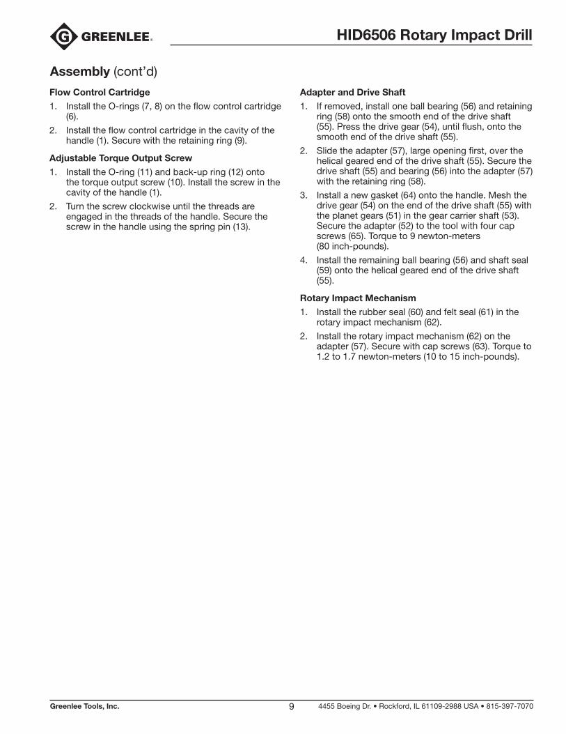
Flow Control Cartridge
1. Install the O-rings (7, 8) on the flow control cartridge (6).
2. Install the flow control cartridge in the cavity of the handle (1). Secure with the retaining ring (9).
Adjustable Torque Output Screw
1. Install the O-ring (11) and back-up ring (12) onto the torque output screw (10). Install the screw in the cavity of the handle (1).
2. Turn the screw clockwise until the threads are engaged in the threads of the handle. Secure the screw in the handle using the spring pin (13).
Adapter and Drive Shaft
1. If removed, install one ball bearing (56) and retaining ring (58) onto the smooth end of the drive shaft (55). Press the drive gear (54), until flush, onto the smooth end of the drive shaft (55).
2. Slide the adapter (57), large opening first, over the helical geared end of the drive shaft (55). Secure the drive shaft (55) and bearing (56) into the adapter (57) with the retaining ring (58).
3. Install a new gasket (64) onto the handle. Mesh the drive gear (54) on the end of the drive shaft (55) with the planet gears (51) in the gear carrier shaft (53). Secure the adapter (52) to the tool with four cap screws (65). Torque to 9 newton-meters (80 inch-pounds).
4. Install the remaining ball bearing (56) and shaft seal (59) onto the helical geared end of the drive shaft (55).
Rotary Impact Mechanism
1. Install the rubber seal (60) and felt seal (61) in the rotary impact mechanism (62).
2. Install the rotary impact mechanism (62) on the adapter (57). Secure with cap screws (63). Torque to 1.2 to 1.7 newton-meters (10 to 15 inch-pounds).
HID6506 Rotary Impact Drill
Greenlee Tools, Inc. 4455 Boeing Dr. • Rockford, IL 61109-2988 USA • 815-397-707010
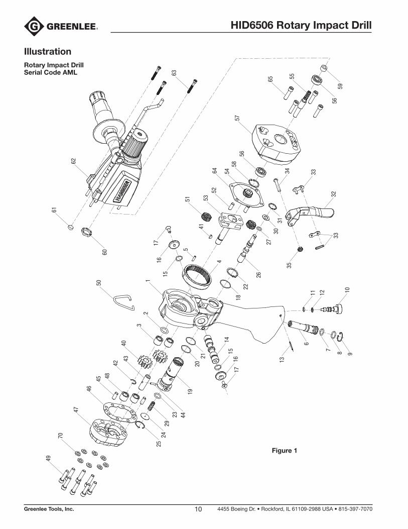
IllustrationRotary Impact Drill Serial Code AML
14
49
70
47
46
45 4842
4043
32
50
1
51
5264 54
5856
57
65 55
2524
2923 44
19
2120
1516
17
3334
1822
26
3130
27
4
1516
17
41
5
61
60
63
62
35
3233
11 12 10
13
6
7 8 9
5956
53
Figure 1

HID6506 Rotary Impact Drill
Greenlee Tools, Inc. 4455 Boeing Dr. • Rockford, IL 61109-2988 USA • 815-397-707011
Parts ListRotary Impact Drill —Serial Code AML (Figure 1)
UPC No. Key 78-3310- Part No. Description Qty
UPC No. Key 78-3310- Part No. Description Qty
1 43482 50434829 HANDLE ASSEMBLY WITH ORIFICE, BEARINGS and GEAR (includes items 2–5) ................................1
2* O-ring, 1/2 x 3/32–90 .............................1
3 41591 50415911 Needle Bearing .......................................2
4 40152 50401524 Internal Gear ...........................................1
5 41593 50415930 Dowel Pin, 1/8 x 1/2 ...............................1
6 43302 50433024 FLOW CONTROL CARTRIDGE (includes items 7 and 8) ..........................1
7* O-ring, 1/2 x 1/16–70 .............................1
8* O-ring, 7/16 x 1/16–70 ...........................1
9 41600 50416003 Retaining Ring, 11/16 Internal ................1
10 41094 50410942 Screw, Adjustable Torque Output ...........1
11* O-ring, 1/4 x 1/16–70 .............................1
12* Back-Up Ring .........................................1
13* Spring Pin, 5/64 x 7/8 .............................1
14 40215 50402154 Spool, Directional ...................................1
15* O-ring, 7/16 x 1/16–68 ...........................2
16 40228 50402283 Button .....................................................2
17 Flat Socket Head Cap Screw, #10–24 x 1/2 ...........................................2
18* O-ring, 7/8 x 1/16–70 .............................1
19 41097 50410971 Sleeve, Super Spool ...............................1
20* O-ring, .787 x .051–70 ............................1
21* O-ring, 3/4 x1/16–90 ..............................1
22 41298 90548191 Retaining Ring, 7/8 External ...................1
23* O-ring, 7/16 x 3/32–90 ...........................1
24 41095 50410952 Cap .........................................................1
25 41712 50417122 Retaining Ring, 3/4 Internal ....................1
26 48681 50486810 Spool, Control ........................................1
27* O-ring, 5/16 x 1/16–70 ...........................1
29 42865 50428651 Spring, Compression ..............................1
30 41096 50410962 Washer ....................................................1
31 41297 50412971 Retaining Ring, 5/8 Internal ....................1
32 40406 50404063 Trigger .....................................................1
33 41636 50416361 Connecting Link .....................................1
34 Slotted Round Head Machine Screw, #10–24 x 1-1/4 ............................1
35 Hex Elastic Stop Nut, #10–24.................1
40 41594 50415940 Gear, 11 Tooth ........................................2
41 40115 50401154 Key, 1/8 x 3/8 ..........................................1
42 41621 50416212 Retaining Ring, 25/64 External ...............1
43 40114 50401144 Shaft Idler ...............................................1
44 41593 50415930 Drive Pin .................................................1
45 41624 50416242 Dowel Pin, 1/4 x 5/8 ...............................2
46* Gasket ....................................................1
47 40405 50404053 MOTOR CAP (includes items 48, 49 and 70) ................1
48 41591 50415911 Needle Bearing .......................................2
49 Socket Head Cap Screw, 1/4–20 x 1 .....8
50 43817 50438174 Hook, Lift ................................................1
51 41080 50410803 Gear, Planet (21 teeth with needle bearing) .......................................2
52 41624 50416242 Dowel Pin, 1/4 x 5/8 ...............................2
53 49590 50495909 Shaft, Gear Carrier ..................................1
54 41075 50410752 Gear, Drive (21 Teeth) .............................1
55 00809 52058178 Shaft, Drive .............................................1
56 42044 50420443 Ball Bearing, 5/16 I.D. .............................2
57† 00805 52058182 Adapter ...................................................1
58† 41457 50414571 Retaining Ring, Internal 7/8 ....................1
59† 00807 52058180 Shaft Seal ...............................................1
60 00802 52058183 Rubber Buffer .........................................1
61 00800 52062555 Felt Seal ..................................................1
62† 00806 52058181 ROTARY IMPACT MECHANISM (includes 60 and 61) (see Figure 2)
42041 50420413 Auxiliary Handle ..................................1
42042 50420423 Depth Gauge .......................................1
63† Cap Screw, #8–32 x 1.250 Socket Head ...........................................3
64* Gasket ....................................................1
65 Cap Screw, 1/4–20 x 1 Socket Head .....4
70 Washer, Flat ............................................8
Decals (not shown)
49842 52001069 Decal, Max. Pressure and Flow .............1
48781 50487817 Decal, Greenlee ......................................1
49489 50494890 Decal, Spool Rotation .............................1
49592 52000976 Decal, Sound ..........................................1
49500 50495003 Decal, Read Instruction Manual .............1
Kits
00794 52062558 Drive Shaft Assembly (includes items 54–56)
* 41115 50411154 Packing Kit (includes all items marked with an asterisk)
† 52058184 Retrofit Kit (converts Serial Code GAT to AML (includes Drive Shaft Assembly and all items marked with †)
HID6506 Rotary Impact Drill
Greenlee Tools, Inc. 4455 Boeing Dr. • Rockford, IL 61109-2988 USA • 815-397-707012
Figure 2
35
34
131
3
2
33 4
5
637
36
910
11
1213
14
7
16
Maintenance Kitincludes
17
18
19
20
21
22
23
24
25
26
28
361617 18
1920
21 22
4324
38 39
41
42
25
15
26
27
30
29
40
28
20
23
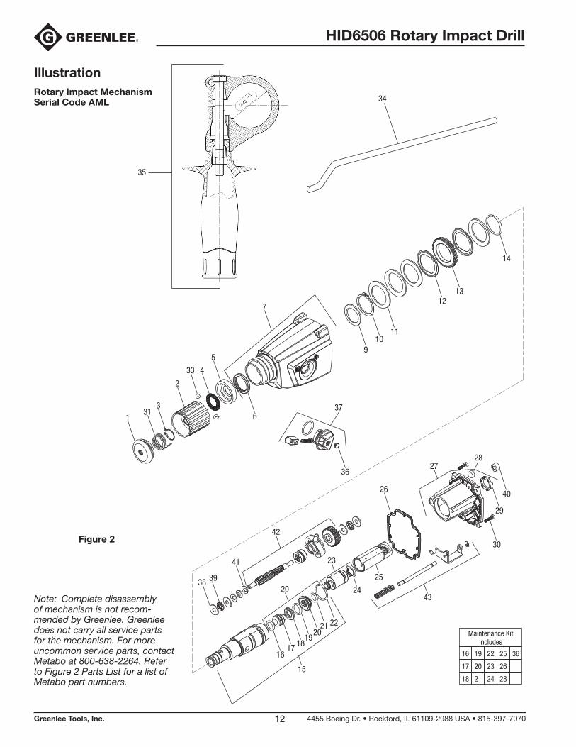
IllustrationRotary Impact Mechanism Serial Code AML
Note: Complete disassembly of mechanism is not recom-mended by Greenlee. Greenlee does not carry all service parts for the mechanism. For more uncommon service parts, contact Metabo at 800-638-2264. Refer to Figure 2 Parts List for a list of Metabo part numbers.
HID6506 Rotary Impact Drill
Greenlee Tools, Inc. 4455 Boeing Dr. • Rockford, IL 61109-2988 USA • 815-397-707013
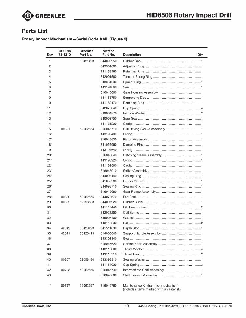
Parts ListRotary Impact Mechanism —Serial Code AML (Figure 2)
UPC No. Greenlee Metabo Key 78-3310- Part No. Part No. Description Qty
1 50421423 344092950 Rubber Cap ...................................................................1
2 343361680 Adjusting Ring ...............................................................1
3 141155460 Retaining Ring ...............................................................1
4 342001560 Tension-Spring Ring ......................................................1
5 343361690 Spacer Ring ..................................................................1
6 143194060 Seal ...............................................................................1
7 316045660 Gear Housing Assembly ...............................................1
9 141153750 Supporting Disc ............................................................1
10 141180170 Retaining Ring ...............................................................1
11 342070340 Cup Spring ....................................................................4
12 339004870 Friction Washer .............................................................2
13 340002750 Spur Gear ......................................................................1
14 141181290 Circlip ............................................................................1
15 00801 52062554 316045710 Drill Driving Sleeve Assembly........................................1
16* 143192400 O-ring ............................................................................1
17* 316045630 Piston Assembly ...........................................................1
18* 341055960 Damping Ring ...............................................................1
19* 143194640 O-ring ............................................................................1
20* 316045640 Catching Sleeve Assembly ...........................................1
21* 143193920 O-ring ............................................................................1
22* 141181860 Circlip ............................................................................1
23* 316048010 Striker Assembly ...........................................................1
24* 344093140 Sealing Ring ..................................................................1
25* 341059260 Exciter Sleeve ...............................................................1
26* 344098710 Sealing Ring ..................................................................1
27 316045680 Gear Flange Assembly ..................................................1
28* 00800 52062555 344070670 Felt Seal ........................................................................1
29 00802 52058183 344095920 Rubber Buffer ................................................................1
30 141119440 Fill. Head Screw ............................................................2
31 342022250 Coil Spring ....................................................................1
32 339007400 Washer ..........................................................................1
33 143115330 Ball ................................................................................2
34 42042 50420423 341511630 Depth Stop ....................................................................1
35 42041 50420413 314000840 Support Handle Assemlby ............................................1
36* 343398340 Seal ...............................................................................1
37 316045620 Control Knob Assembly ................................................1
38 143115300 Thrust Washer ...............................................................4
39 143115310 Thrust Bearing ...............................................................2
40 00807 52058180 343398310 Sealing Washer .............................................................1
41 141154920 Cup Spring ....................................................................3
42 00798 52062556 316045730 Intermediate Gear Assembly .........................................1
43 316045600 Shift Element Assemlby ................................................1
* 00797 52062557 316045760 Maintenance Kit (hammer mechanism) (includes items marked with an asterisk)
HID6506 Rotary Impact Drill
Greenlee Tools, Inc. 4455 Boeing Dr. • Rockford, IL 61109-2988 USA • 815-397-707014
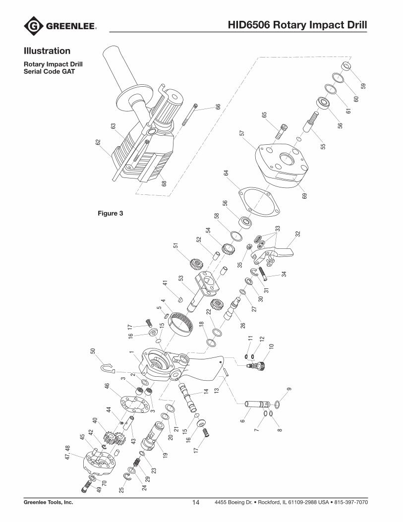
IllustrationRotary Impact Drill Serial Code GAT
32
34
11
15
12
14
10
9
3130
27
26
87
6
1716
15
13
19
2329
2021
324
43
25
35
33
181716
22
12
50
4644
4042
45
47, 4
8
3
45
41
5351
52
5458
5664
57
65
66
5960
6156
55
62
63
68
69
4970
Figure 3
HID6506 Rotary Impact Drill
Greenlee Tools, Inc. 4455 Boeing Dr. • Rockford, IL 61109-2988 USA • 815-397-707015
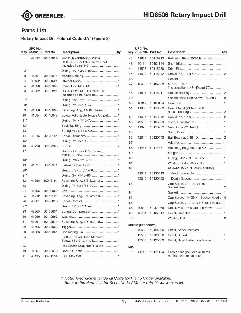
Parts ListRotary Impact Drill —Serial Code GAT (Figure 3)
UPC No. Key 78-3310- Part No. Description Qty
UPC No. Key 78-3310- Part No. Description Qty
1 43482 50434829 HANDLE ASSEMBLY WITH ORIFICE, BEARINGS and GEAR (includes items 2–5) ................................1
2* O-ring, 1/2 x 3/32–90 .............................1
3 41591 50415911 Needle Bearing .......................................2
4 40152 50401524 Internal Gear ...........................................1
5 41593 50415930 Dowel Pin, 1/8 x 1/2 ...............................1
6 43302 50433024 FLOW CONTROL CARTRIDGE (includes items 7 and 8) ..........................1
7* O-ring, 1/2 x 1/16–70 .............................1
8* O-ring, 7/16 x 1/16–70 ...........................1
9 41600 50416003 Retaining Ring, 11/16 Internal ................1
10 41094 50410942 Screw, Adjustable Torque Output ...........1
11* O-ring, 1/4 x 1/16–70 .............................1
12* Back-Up Ring .........................................1
13* Spring Pin, 5/64 x 7/8 .............................1
14 40215 50402154 Spool, Directional ...................................1
15* O-ring, 7/16 x 1/16–68 ...........................2
16 40228 50402283 Button .....................................................2
17 Flat Socket Head Cap Screw, #10–24 x 1/2 ...........................................2
18* O-ring, 7/8 x 1/16–70 .............................1
19 41097 50410971 Sleeve, Super Spool ...............................1
20* O-ring, .787 x .051–70 ............................1
21* O-ring, 3/4 x1/16–90 ..............................1
22 41298 90548191 Retaining Ring, 7/8 External ...................1
23* O-ring, 7/16 x 3/32–90 ...........................1
24 41095 50410952 Cap .........................................................1
25 41712 50417122 Retaining Ring, 3/4 Internal ....................1
26 48681 50486810 Spool, Control ........................................1
27* O-ring, 5/16 x 1/16–70 ...........................1
29 42865 50428651 Spring, Compression ..............................1
30 41096 50410962 Washer ....................................................1
31 41297 50412971 Retaining Ring, 5/8 Internal ....................1
32 40406 50404063 Trigger .....................................................1
33 41636 50416361 Connecting Link .....................................1
34 Slotted Round Head Machine Screw, #10–24 x 1-1/4 ............................1
35 Hex Elastic Stop Nut, #10–24.................1
40 41594 50415940 Gear, 11 Tooth ........................................2
41 40115 50401154 Key, 1/8 x 3/8 ..........................................1
42 41621 50416212 Retaining Ring, 25/64 External ...............1
43 40114 50401144 Shaft Idler ...............................................1
44 41593 50415930 Drive Pin .................................................1
45 41624 50416242 Dowel Pin, 1/4 x 5/8 ...............................2
46* Gasket ....................................................1
47 40405 50404053 MOTOR CAP (includes items 48, 49 and 70) ................1
48 41591 50415911 Needle Bearing .......................................2
49 Socket Head Cap Screw, 1/4–20 x 1 .....8
50 43817 50438174 Hook, Lift ................................................1
51 41080 50410803 Gear, Planet (21 teeth with needle bearing) .......................................2
52 41624 50416242 Dowel Pin, 1/4 x 5/8 ...............................2
53 49590 50495909 Shaft, Gear Carrier ..................................1
54 41075 50410752 Gear, Drive (21 Teeth) .............................1
55 Shaft, Drive .............................................1
56 42044 50420443 Ball Bearing, 5/16 I.D. .............................2
57 Adapter ...................................................1
58 41457 50414571 Retaining Ring, Internal 7/8 ....................1
59 Slinger .....................................................1
60 O-ring, .722 x .850 x .065 .......................1
61 Washer, .694 x .856 x .008 .....................1
62 ROTARY IMPACT MECHANISM†
42041 50420413 Auxiliary Handle ..................................1
42042 50420423 Depth Gauge .......................................1
63 Cap Screw, #10–24 x 1.50 Socket Head ...........................................2
64* Gasket ....................................................1
65 Cap Screw, 1/4–20 x 1 Socket Head .....4
66 Cap Screw, #10–24 x 1 Socket Head .....1
68 49842 52001069 Decal, Max. Pressure and Flow .............1
69 48781 50487817 Decal, Greenlee ......................................1
70 Washer, Flat ............................................8
Decals (not shown)
49489 50494890 Decal, Spool Rotation .............................1
49592 52000976 Decal, Sound ..........................................1
49500 50495003 Decal, Read Instruction Manual .............1
Kits
* 41115 50411154 Packing Kit (includes all items marked with an asterisk)
† Note: Mechanism for Serial Code GAT is no longer available. Refer to the Parts List for Serial Code AML for retrofit conversion kit.

4455 Boeing Drive • Rockford, IL 61109-2988 • USA • 815-397-7070©2019 Greenlee Tools, Inc. • An ISO 9001 Company
USA Tel: 800-435-0786 Fax: 800-451-2632
Canada Tel: 800-435-0786 Fax: 800-524-2853
International Tel: +1-815-397-7070 Fax: +1-815-397-9247
www.greenlee.com