hierarchical modeling
DESCRIPTION
verilogTRANSCRIPT

Abstraction in Hardware Design
� Remember from last lecture that HDLs offer a textual description of a netlist.
� Through abstraction in the HDL, we can capture more than a single transistor or gate at a time.
� Similar to a function call in C that abstracts a large collection of expressions
� Similar to a Lego® castle that abstracts a large collection of
Patrick SchaumontSpring 2008
ECE 4514 Digital Design IILecture 2: Hierarchical Design
� Similar to a Lego castle that abstracts a large collection of Lego® bricks
� Verilog offers three types of abstraction
� Structural
� Dataflow
� Behavioral
These two are related, we call both of them just 'behavioral' for now
Structural Modeling
QB
Q
R
S
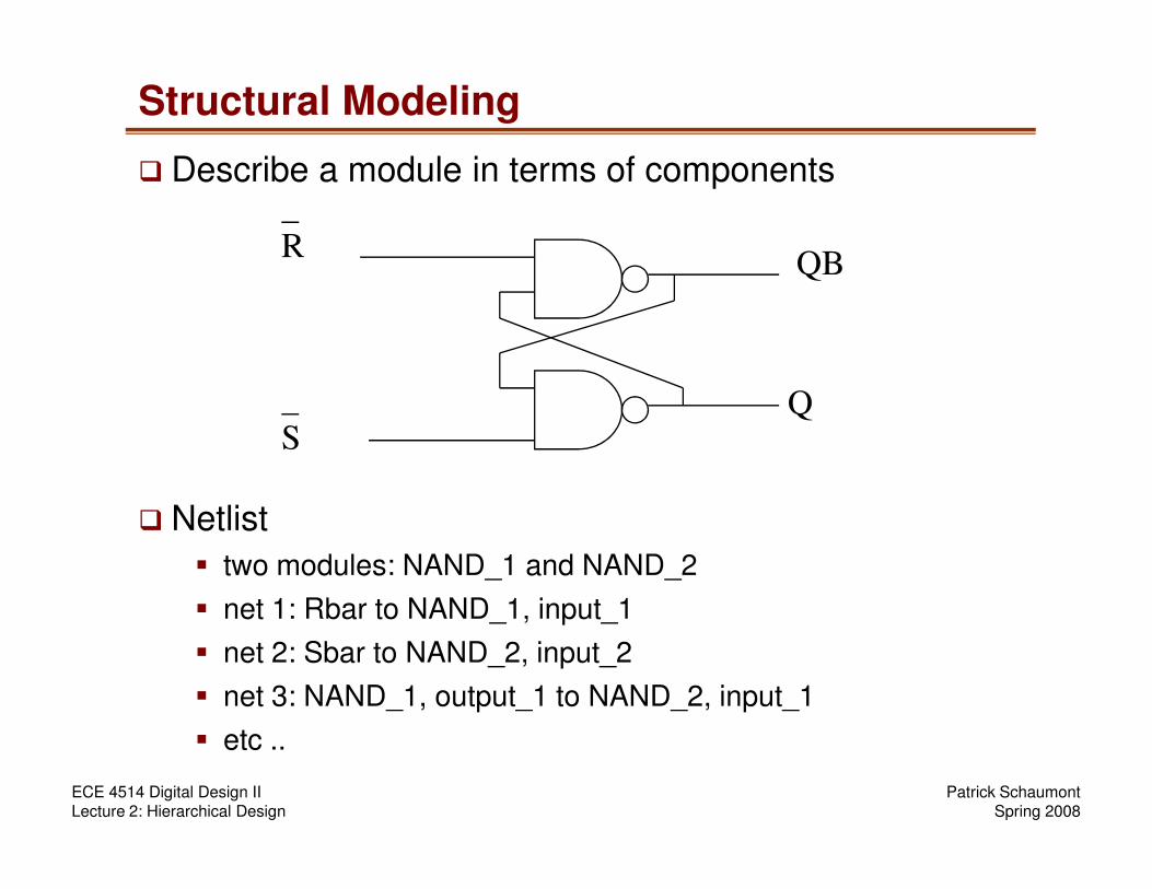
� Describe a module in terms of components
Patrick SchaumontSpring 2008
ECE 4514 Digital Design IILecture 2: Hierarchical Design
� Netlist
� two modules: NAND_1 and NAND_2
� net 1: Rbar to NAND_1, input_1
� net 2: Sbar to NAND_2, input_2
� net 3: NAND_1, output_1 to NAND_2, input_1
� etc ..
S

Behavioral Modeling
� Describe a module in terms of input-output behavior
input S, R;
output Q, QB;
if ( S == ‘1’) and (R == ‘0’) then
Patrick SchaumontSpring 2008
ECE 4514 Digital Design IILecture 2: Hierarchical Design
Set Q to ‘1’, set QB to ‘0’
else if ( S == ‘1’) and (R == ‘1’) then
Set Q to ‘1’, set QB to ‘1’
else if ( S == ‘0’) and (R == ‘0’) then
*Hold current state*
else if ( S == ‘0’) and (R == ‘1’) then
Set Q to ‘0’, set QB to ‘1’

Behavioral and Structural are dual mechanisms
my_flop
Rbar
Sbar
Q
Qbar
Patrick SchaumontSpring 2008
ECE 4514 Digital Design IILecture 2: Hierarchical Design
Behavioral Descriptionexplains what happens
to Q and Qbar in terms ofRbar and Sbar
Structural Descriptionexplains what happens
to Q and Qbar in terms ofa netlist of lower-level
components
Structural and Behavioral are related
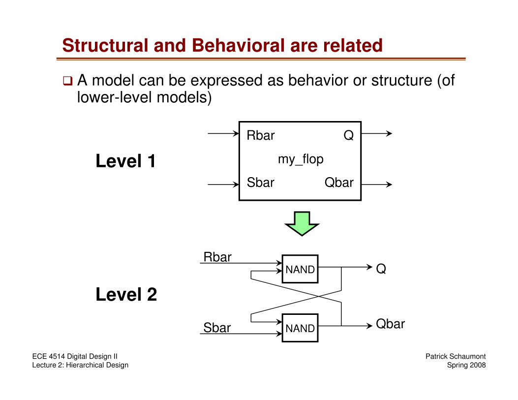
� A model can be expressed as behavior or structure (of lower-level models)
my_flop
Rbar
Sbar
Q
Qbar
Level 1
Patrick SchaumontSpring 2008
ECE 4514 Digital Design IILecture 2: Hierarchical Design
Q
QbarSbar
RbarNAND
NAND
Level 2

Top-down design
my_pc
motherboard
harddiskcontroller cpu memory
iocontroller
integer
Start here, rewrite behavior into structure until
you reach primitive behavior
Patrick SchaumontSpring 2008
ECE 4514 Digital Design IILecture 2: Hierarchical Design
integerunit cache regfile
ALU shifter
NAND NOR Leaf Cells of Primitive Behavior

Bottom-up design
my_pc
motherboard
harddiskcontroller cpu memory
iocontroller
integer
Equivalent Top-level Behavior
Patrick SchaumontSpring 2008
ECE 4514 Digital Design IILecture 2: Hierarchical Design
integerunit cache regfile
ALU shifter
NAND NORStart here, compose structure into
larger modules until you reach
equivalent top-level behavior
Bottom-up, Top-down are both useful
� When re-using modules from one design to the next: bottom-up
� When developing new modules from scratch: top-down
� In practice, top-down and bottom-up techniques are combined.
Patrick SchaumontSpring 2008
ECE 4514 Digital Design IILecture 2: Hierarchical Design
� In Verilog, a given module can be expressed as structure or else as behavior.
� There are two flavors of 'behavior' in Verilog
� Behavioral: similar to a sequential description in C
� Dataflow: a collection of concurrent expressions

Example of a hierarchical model
� 4-bit counter
q3q2q1q0
q q q q
T-ff T-ff T-ff T-ff
Patrick SchaumontSpring 2008
ECE 4514 Digital Design IILecture 2: Hierarchical Design
reset
� Top-level structure contains 4 interconnected T flip-flops
T flip-flop, behavior
q
T-ff
reset
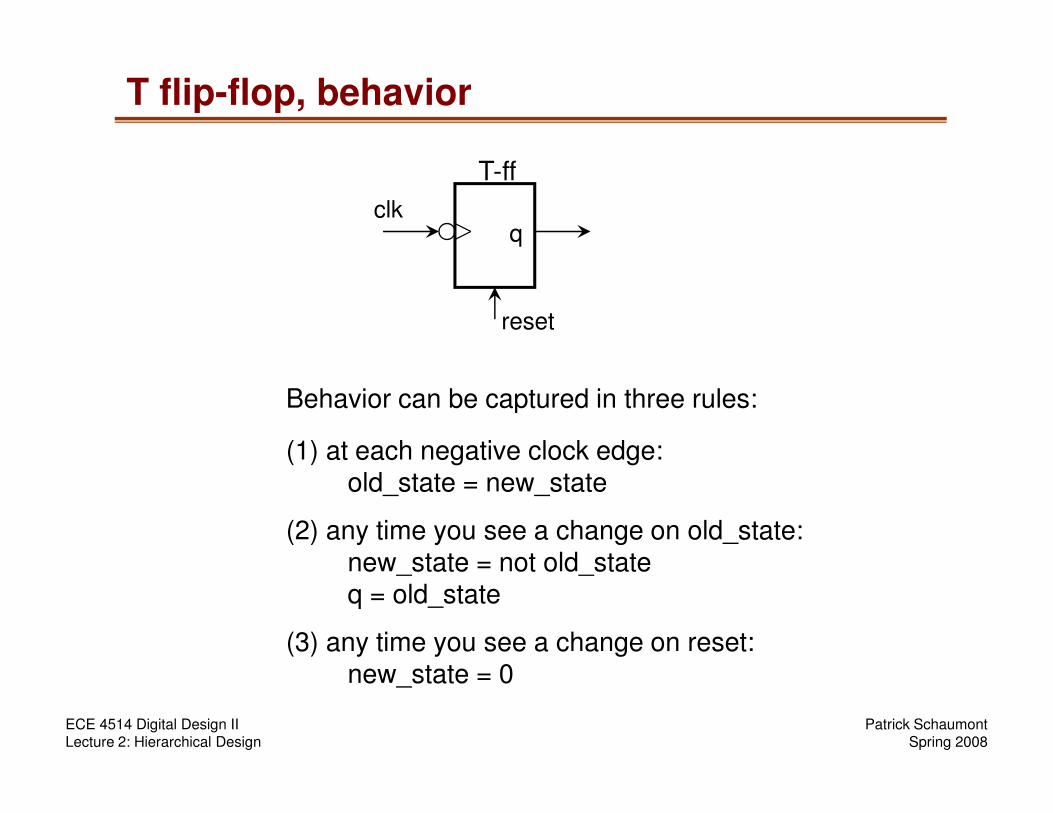
Behavior can be captured in three rules:
clk
Patrick SchaumontSpring 2008
ECE 4514 Digital Design IILecture 2: Hierarchical Design
at each negative clock edge:old_state = new_state
any time you see a change on old_state:new_state = not old_stateq = old_state
any time you see a change on reset:new_state = 0
Behavior can be captured in three rules:
(1)
(2)
(3)
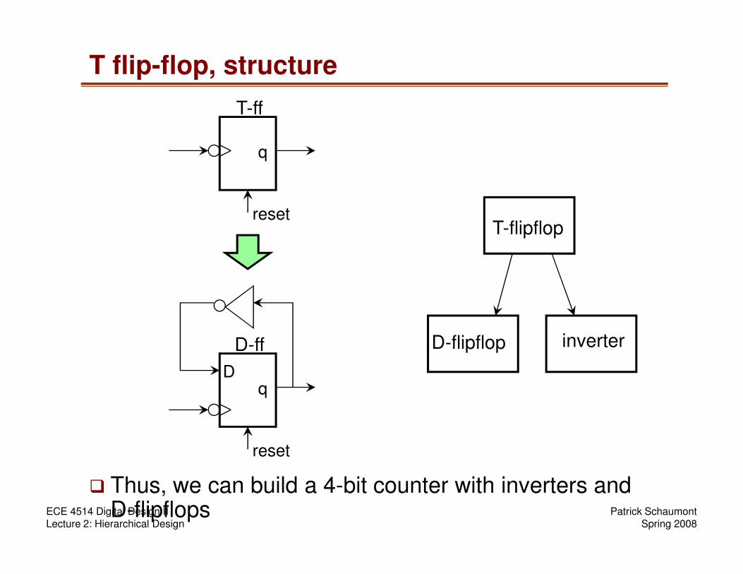
T flip-flop, structure
q
T-ff
resetT-flipflop
Patrick SchaumontSpring 2008
ECE 4514 Digital Design IILecture 2: Hierarchical Design
� Thus, we can build a 4-bit counter with inverters and D-flipflops
q
D-ff
reset
D
D-flipflop inverter

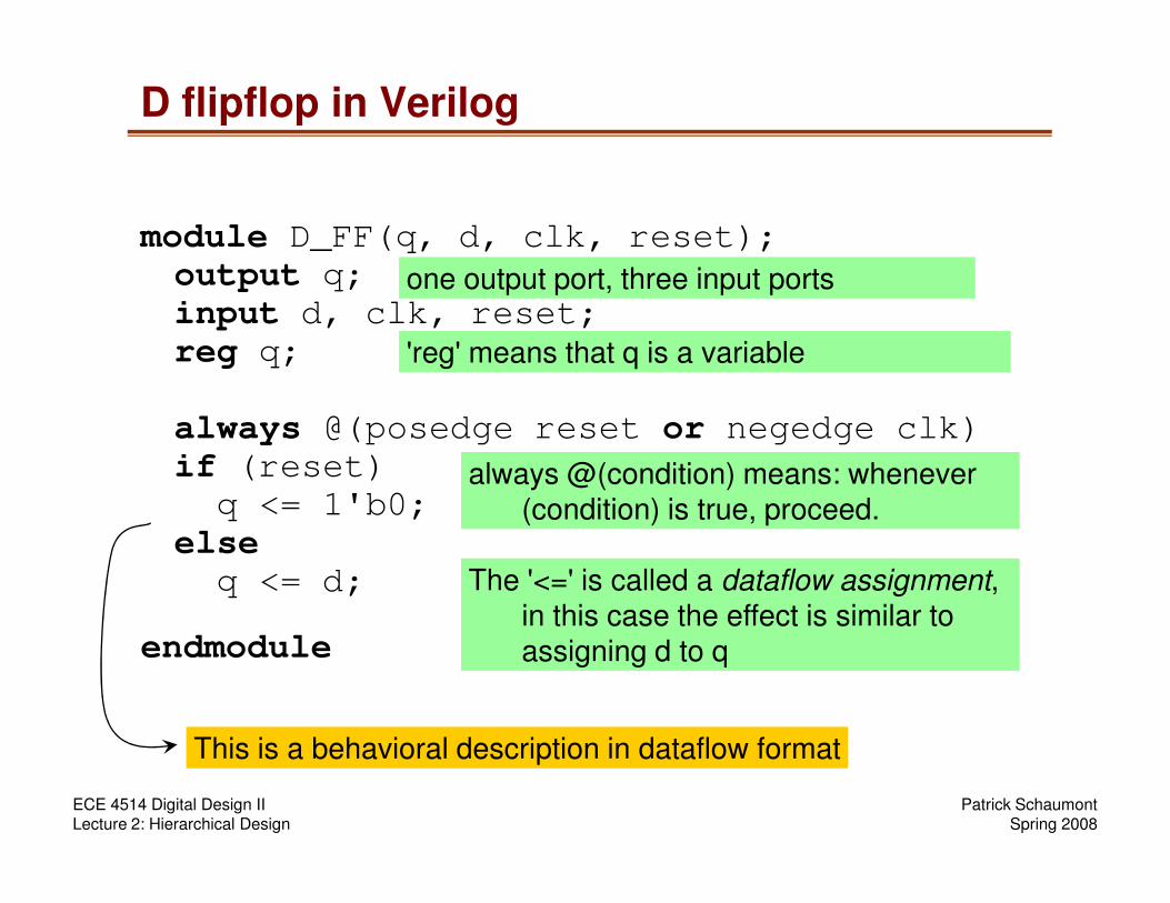
D flipflop in Verilog
module D_FF(q, d, clk, reset);
output q;
input d, clk, reset;
reg q;
always @(posedge reset or negedge clk)
if (reset)
Patrick SchaumontSpring 2008
ECE 4514 Digital Design IILecture 2: Hierarchical Design
if (reset)
q <= 1'b0;
else
q <= d;
endmodule
D flipflop in Verilog
module D_FF(q, d, clk, reset);
output q;
input d, clk, reset;
reg q;
always @(posedge reset or negedge clk)
if (reset)
one output port, three input ports
'reg' means that q is a variable
Patrick SchaumontSpring 2008
ECE 4514 Digital Design IILecture 2: Hierarchical Design
if (reset)
q <= 1'b0;
else
q <= d;
endmodule
always @(condition) means: whenever (condition) is true, proceed.
The '<=' is called a dataflow assignment, in this case the effect is similar to assigning d to q
This is a behavioral description in dataflow format

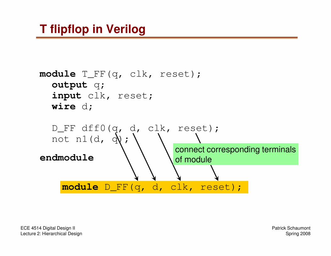
T flipflop in Verilog
module T_FF(q, clk, reset);
output q;
input clk, reset;
wire d;
D_FF dff0(q, d, clk, reset);
Patrick SchaumontSpring 2008
ECE 4514 Digital Design IILecture 2: Hierarchical Design
D_FF dff0(q, d, clk, reset);
not n1(d, q);
endmodule
T flipflop in Verilog
module T_FF(q, clk, reset);
output q;
input clk, reset;
wire d;
D_FF dff0(q, d, clk, reset);
Patrick SchaumontSpring 2008
ECE 4514 Digital Design IILecture 2: Hierarchical Design
D_FF dff0(q, d, clk, reset);
not n1(d, q);
endmodule
module D_FF(q, d, clk, reset);
connect corresponding terminalsof module

T flipflop in Verilog
module T_FF(q, clk, reset);
output q;
input clk, reset;
wire d;
D_FF dff0(q, d, clk, reset);
one output port, two input ports
a wire d has no storage: its value is always determined in terms of other variables
Patrick SchaumontSpring 2008
ECE 4514 Digital Design IILecture 2: Hierarchical Design
D_FF dff0(q, d, clk, reset);
not n1(d, q);
endmodule
'not' is a primitive in Verilog: the simulator understands what this module does.
This is a structural description
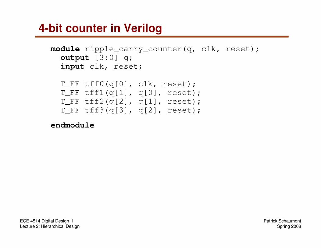
4-bit counter in Verilog
module ripple_carry_counter(q, clk, reset);
output [3:0] q;
input clk, reset;
T_FF tff0(q[0], clk, reset);
T_FF tff1(q[1], q[0], reset);
T_FF tff2(q[2], q[1], reset);
T_FF tff3(q[3], q[2], reset);
endmodule
Patrick SchaumontSpring 2008
ECE 4514 Digital Design IILecture 2: Hierarchical Design
endmodule
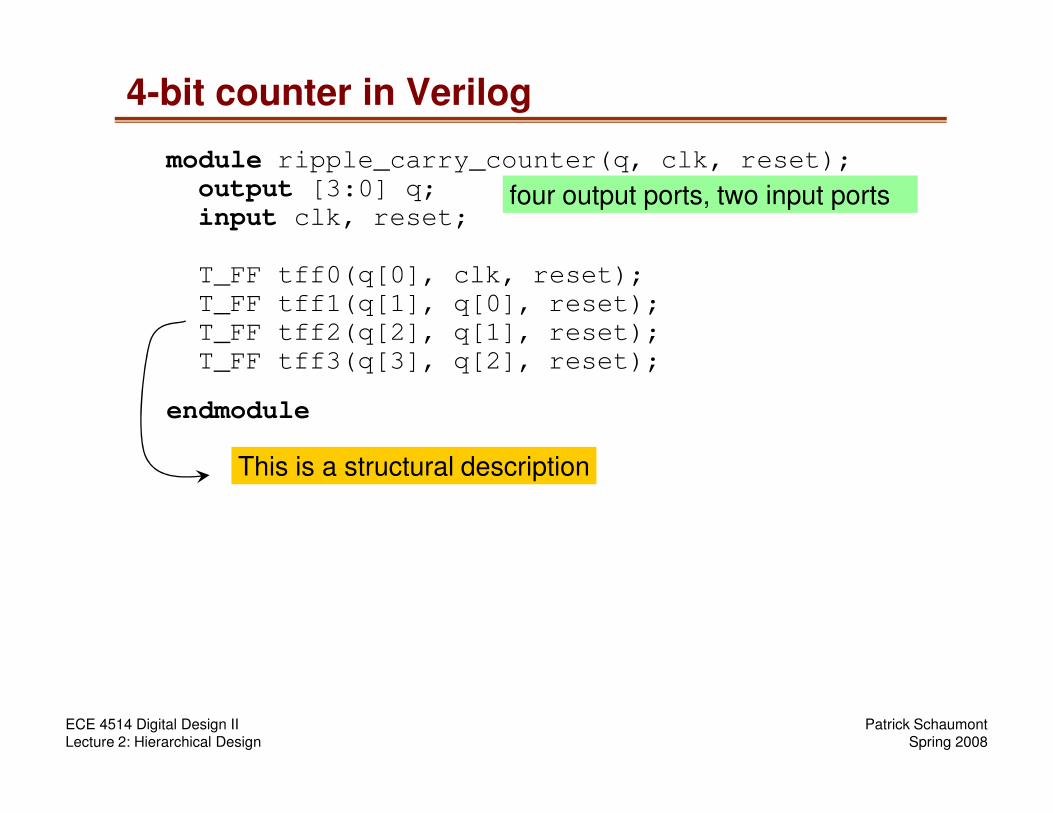
4-bit counter in Verilog
module ripple_carry_counter(q, clk, reset);
output [3:0] q;
input clk, reset;
T_FF tff0(q[0], clk, reset);
T_FF tff1(q[1], q[0], reset);
T_FF tff2(q[2], q[1], reset);
T_FF tff3(q[3], q[2], reset);
endmodule
four output ports, two input ports
Patrick SchaumontSpring 2008
ECE 4514 Digital Design IILecture 2: Hierarchical Design
endmodule
This is a structural description
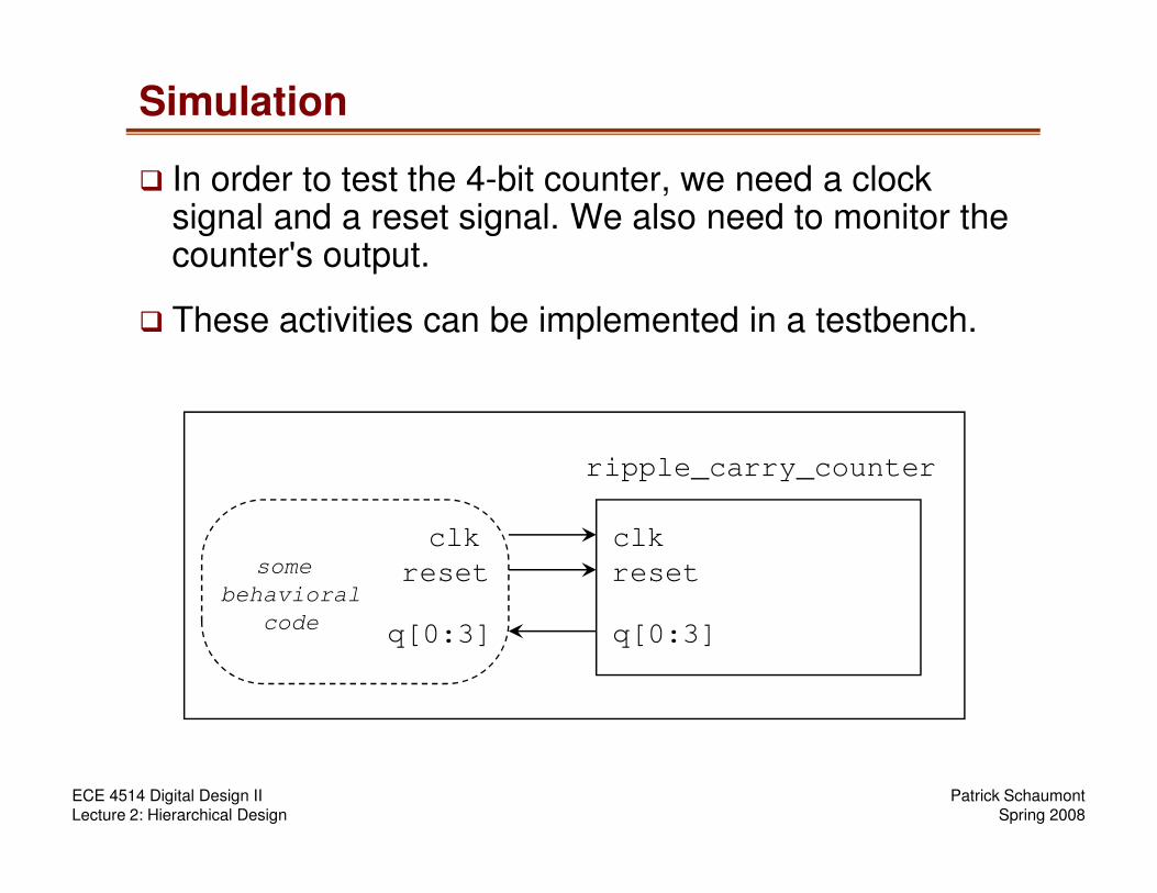
Simulation
� In order to test the 4-bit counter, we need a clock signal and a reset signal. We also need to monitor the counter's output.
� These activities can be implemented in a testbench.
Patrick SchaumontSpring 2008
ECE 4514 Digital Design IILecture 2: Hierarchical Design
ripple_carry_counter
some
behavioral
code
clk
reset
q[0:3] q[0:3]
reset
clk
Testbench
module stimulus;
reg clk;
reg reset;
wire [3:0] q;
ripple_carry_counter(q, clk,reset);
initial
clk = 1'b0;
always
#5 clk = ~clk;
Patrick SchaumontSpring 2008
ECE 4514 Digital Design IILecture 2: Hierarchical Design
#5 clk = ~clk;
initial
begin
reset = 1'b1;
#15 reset = 1'b0;
#180 reset = 1'b1;
#10 reset = 1'b0;
#20 $finish;
end
initial
$monitor($time, " Output q = %d", q);
endmodule

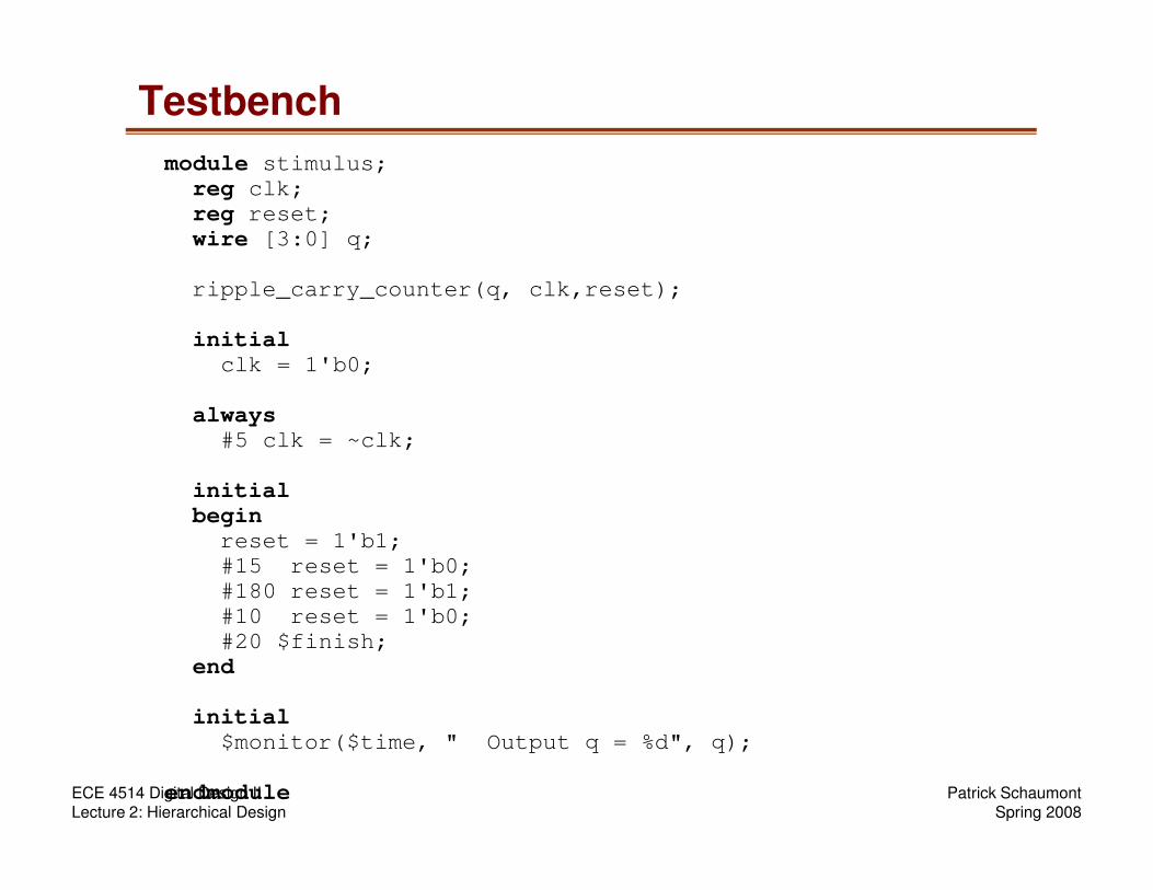
Testbench
module stimulus;
reg clk;
reg reset;
wire [3:0] q;
ripple_carry_counter(q, clk,reset);
initial
clk = 1'b0;
always
#5 clk = ~clk;
when simulation starts, clk is low
each 5 time units, clk will flip value
Patrick SchaumontSpring 2008
ECE 4514 Digital Design IILecture 2: Hierarchical Design
#5 clk = ~clk;
initial
begin
reset = 1'b1;
#15 reset = 1'b0;
#180 reset = 1'b1;
#10 reset = 1'b0;
#20 $finish;
end
initial
$monitor($time, " Output q = %d", q);
endmodule
each 5 time units, clk will flip value
when simulation starts, reset is high.after 15 time units, reset is low.after 180 time units, reset is high.after 10 time units, reset is low.after 20 time units, stop simulation.
each time q changes, print its value
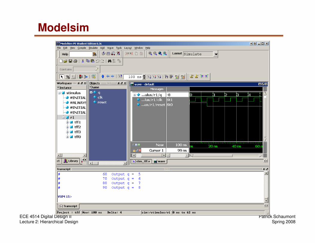
Modelsim
Patrick SchaumontSpring 2008
ECE 4514 Digital Design IILecture 2: Hierarchical Design
Summary
� Behavioral and Structural Modeling are two
complementary forms for Hardware Description
� They are linked with top-down (behavior into structure) or
bottom-up (structure into behavior) design
� 4-bit counter as an example of bottom-up design
� Check design files on Blackboard
Patrick SchaumontSpring 2008
ECE 4514 Digital Design IILecture 2: Hierarchical Design