high aspect ratio wing design: optimal aerostructural...
TRANSCRIPT
High Aspect Ratio Wing Design: Optimal AerostructuralTradeoffs for the Next Generation of Materials
Graeme J. Kennedy∗
Georgia Institute of Technology, School of Aerospace Engineering, Atlanta, Georgia
Gaetan W. Kenway† and Joaquim R. R. A. Martins‡
University of Michigan, Department of Aerospace Engineering, Ann Arbor, Michigan
Current and future composite material technologies have the potential to greatly improve the per-formance of large transport aircraft. However, the coupling between aerodynamics and structuresmakes it challenging to design optimal flexible wings, and the transonic flight regime requires highfidelity computational models. We address these challenges by solving a series of medium- and high-fidelity aerostructural optimization problems that explore the design space for the wing of a largetransport aircraft. We consider three different materials: aluminum, carbon-fiber reinforced com-posites and an hypothetical composite based on carbon nanotubes. The design variables consist ofboth aerodynamic shape (including span), and structural sizing, as well as ply angle fractions in thecase of composites. Pareto fronts with respect to takeoff weight and fuel burn are generated. Thewing performance in each case is optimized subject to stress and buckling constraints. We foundthat composite wings consistently resulted in lower fuel burn and lower structural weight, and thatthe carbon nanotube composite did not yield the increase in performance one would expect from amaterial with such outstanding properties. This was in part due to the minimum structural thicknessconstraint. For all materials, the minimum fuel burn wings were found to be longer, heavier, thinner,more flexible, and more lightly loaded than their minimum TOGW counterparts.
I. IntroductionThe growing concern about the effect of green-house gas emissions on climate change, together with the rise in fuel
prices, has lead to increased research on efficient aircraft. This research is crucial if aviation is to remain sustainable,both from the environmental and from the economic viewpoints. To this end, NASA has been developing compu-tational tools, technologies, and concepts to make significant improvements in the energy efficiency of commercialaviation.
NASA’s high aspect ratio wing work under the Fixed Wing project, in particular, aims to explore ways to increasewing aspect ratio in order to reduce fuel burn [9]. The minimization of fuel burn represents a tradeoff betweenstructural weight minimization and drag minimization. However, the fuel burn minimization tradeoff is biased towardsdesigns that have higher structural weights than current aircraft, as current aircraft are designed to strike a balancebetween acquisition cost (which correlates with weight) and operation cost (which depends mostly on fuel burn).
As a consequence of seeking better fuel burn due to higher fuel prices, the trend in the wing design of transportaircraft has been to increase the aspect ratio to improve the lift-to-drag ratio (L/D). The Boeing 787, for example,has an aspect ratio of 11, which is 10% higher than the Boeing 777-300ER (AR = 10) and even higher than the olderBoeing 747-400 (AR = 8). This trend is driven by increases in fuel price, which push the design tradeoffs towardhigher L/D. This increase in aspect ratio has also been observed in previous aerostructural design optimizationstudies by the authors [14, 12]. This was such an important factor for the planned Boeing 777X that it will use afolding mechanism (which incurs an additional weight penalty) to enable a large span while remaining in the samegate span constraint code.
To enable larger wing aspect ratios we can: (1) develop and implement new airframe technologies and (2) developand apply new design methodologies that maximize the benefit of a new airframe technology. In this work, we focuson the latter by considering new materials and exploring the wing design space using medium- and high-fidelitymultidisciplinary design optimization (MDO) methods. This wing design exploration requires the consideration ofboth aerodynamics and structures, not only due to the tradeoffs between drag and structural weight we just mentioned,∗Assistant Professor, AIAA Member†Postdoctoral Research Fellow, AIAA Member‡Associate Professor, AIAA Associate Fellow
1 of 24
American Institute of Aeronautics and Astronautics

but also due to the wing flexibility, which intrinsically couples these two disciplines. This is especially important inthe high aspect ratio wings considered in this study, since wings become more flexible as aspect ratio is increased. Toconsider this coupling, we use aerostructural optimization, which simultaneously performs the structural sizing and theaerodynamic shape optimization, naturally leading to optimally static aeroelastic tailored wings. Such wings exhibithigh aerodynamic performance at cruise conditions while avoiding an excessive weight penalty (which is determinedby structural sizing at critical flight conditions). This is made possible largely by tailoring the wing flexibility toachieve passive load alleviation, as shown previously by the authors [14].
Since the bulk of commercial air transport is performed by aircraft operating in the transonic flow regime, it isimperative to use computational fluid dynamics (CFD) aerodynamic models that consider compressibility effects. Onthe structural side, it is important to include a detailed model of the structural wing box, since an accurate quantificationof the tradeoff between aerodynamic shape and wing weight is required.
Although there has been much research into aerodynamic shape optimization based on the solution of the Eulerequations, we have found that the resulting airfoil shapes differ significantly from shapes obtained with optimizationbased on the Reynolds-averaged Navier–Stokes (RANS) equations [19]. Previous results in Euler-based aerostructuraloptimization also show that unrealistic airfoil shapes are obtained due to the inability of the Euler equations to predictthe shock strength and position, which is strongly coupled to viscous effects [14]. Since the cost of RANS-basedoptimization is high, the approach we take in the present work is to use a much faster panel method for a broaderexploration of the aerostructural design space (as previously done by Kennedy and Martins [12]), and then selectsmaller design spaces of interest for further refinement using RANS-based aerostructural optimization.
The quantification of the tradeoff between acquisition cost and operation cost varies significantly between airlines,aircraft types, and is highly dependent on fuel price. Therefore, it is important to consider various objective functionsbetween the two extremes of minimum fuel burn and minimum weight. To address this issue, we study optimal designsthat minimize fuel burn, takeoff gross weight (TOGW), and several objectives representing a compromise betweenthese two. The result of this multiobjective study is a Pareto front that quantifies the weight penalty of minimizing fuelburn relative to the minimum TOGW design, as well as how that weight penalty varies as the objective varies betweenfuel burn and TOGW.
When it comes to the technology, we chose to explore the use of different materials and seek the answers to twoquestions: (1) Can we take further advantage of carbon-fiber reinforced polymer (CFRP) composites by tailoring ofthe flexibility through the optimization of ply angle orientation, and (2) What if we had a material that had an order ofmagnitude higher strength and stiffness relative to CFRP? How well would a wing made with such material perform,and what would it look like?
To answer these questions, we consider three different materials: an aluminum alloy, a CFRP composite, and anhypothetical composite based on carbon nanotube (CNT) fibers. Aluminum alloys have been used for many decadesand are well understood, so aluminum is used to provide a reference. While CFRP composites are now used inthe primary structure of the two latest wide-body airliners (the Boeing 787 and Airbus A350), the design of CFRPcomposite wings still does not take full advantage of the additional design freedom provided by ply angle orientations.Finally, the CNT-based composite results should give us an idea of what wing designs will look like when vastlysuperior materials are available.
In the following sections, we describe a series of structural and aerostructural design problems that we solved. Theobjective of this sequence of design problems is to evaluate the impact of new structural material technologies on thetradeoffs in the design of a conventional aircraft wing. In order to perform this assessment, we use a series of structuraland coupled aerostructural optimization problems. Optimization of each candidate design is necessary to make a faircomparison between the different materials, so that the full benefit of the potential technology is realized. Comparingsub-optimal designs would lead to incorrect conclusions regarding the relative merits of different materials. However,the design optimization problem must also adequately capture the requirements and objective of a realistic aircraftdesign problem, otherwise the predicted performance improvements may be a result of an incomplete analysis or aninadequate design.
The remainder of this paper is structured as follows: in Section II we describe the essential aspects of the analysisand design tools used in this study. The parametric baseline wing that was used as the starting point for all theoptimizations is described in Section III. In Section IV we describe the details of the structural design parametrizationsthat we used, followed by the aerostructural design problem formulation in Section V. The results are presented anddiscussed in Section VI, and then we finish with conclusions and recommendations for future work in the last section.
2 of 24
American Institute of Aeronautics and Astronautics
II. Analysis and design toolsAs previously mentioned, it is crucial to consider the coupling between the structural flexibility and aerodynamic
loads when performing wing analysis and design. In this study, this is achieved through static aeroelastic analysis, oraerostructural analysis, where the aerodynamic forces on the deformed flying shape of the aircraft are in equilibriumwith the internal forces. All the functions of interest in the design problem we consider—objective functions andconstraints—are evaluated using aerostructural analysis to capture the effect of the structural flexibility on cruiseaerodynamic performance, as well as the effect of the aerodynamic shape on the structural stresses. This is particularlyimportant for higher aspect ratio wings, which tend to be more flexible.
To perform aerostructural analysis, we use both a medium fidelity method that uses a panel method (with com-pressibility, viscous, and wave drag corrections) coupled to a high-fidelity finite-element solver, as well as a RANSCFD solver coupled to the same finite-element solver. In this section we provide a brief description of these aerody-namic and structural solver, and how they are coupled to perform aerostructural analysis. More details are providedby Kennedy and Martins [11] and Kenway et al. [15].
Due to the large dimensionality of the design space and the computational cost of the analysis, we use a gradient-based optimization algorithm [4, 27] together with an adjoint method for evaluating the required gradients. Adjointmethods enable the efficient evaluation of gradients in large dimensional spaces and have been used in both aero-dynamic shape [7, 20, 18] and structural design optimization [34, 33, 28]. Since we are considering aerostructuralcoupling, we require a coupled adjoint that computes gradients of the aerostructural system with respect to both exter-nal shape and internal structural sizing. Again, we provide only a brief description of these techniques in this section;additional details can be found in our previous work [11, 15].
A. Aerodynamic analysisThe medium-fidelity aerodynamic analysis consists of a panel code that computes the pressure distribution over thewing, which is then transfered to the structural analysis. Since this panel code is only able to compute induceddrag, we also estimate the viscous drag and the drag due to compressibility. The RANS CFD includes all these dragcomponents.
1. Panel code and induced drag
For the medium-fidelity aerostructural cases, the aerodynamic analysis is performed using TriPan, an unstructured,three-dimensional parallel panel code for calculating the aerodynamic forces, moments, and pressures for inviscid,incompressible, external lifting flows using the Prandtl–Glauert equation [11]. TriPan uses constant first-order sourceand doublet singularity elements distributed over the entire lifting surface and doublet elements distributed over thewake [10]. The source strengths are determined based on the onset flow conditions, while the boundary conditions forthe doublet strengths form a dense linear system of equations, represented here by
RA(w,u) = 0, (1)
where u and w are vectors of the structural and aerodynamic state variables, respectively. The linear system repre-sented by Equation (1) is solved in parallel using PETSc [1]. A dense matrix format is used for the matrix-vectorproducts, while a sparse approximate-Jacobian is used to form a incomplete LU (ILU) preconditioner. The linearsystem is solved using the Krylov subspace method GMRES.
The lift-induced drag is computed directly from TriPan using a Trefftz-plane integration.
2. Viscous drag
The viscous drag is computed by dividing the wing into chordwise strips, estimating the profile drag coefficients ofthe corresponding airfoil sections, and then integrating the drag in the spanwise direction. The profile drag coefficientsare computed based on a quadratic model:
cdp = cd0 + cd2c2l , (2)
where cl is the sectional lift coefficient, and cd0 and cd2 are coefficients defined below. The coefficient cd0 is based onthe skin friction estimate
cd0 = Fccf ,
3 of 24
American Institute of Aeronautics and Astronautics

where cf is the turbulent skin-friction coefficient determined using the van Driest II method [6], and Fc is a factor thatcorrects this estimate to account for form drag. This factor is given by an empirical function of the airfoil thickness-to-chord ratio, t/c, as follows:
Fc = 1 + 2.7
(t
c
)+ 100
(t
c
)4
.
Finally, the quadratic coefficient in Equation (2) is obtained using the empirical relationship by Wakayama and Kroo[35]:
cd2 =0.38
cos2 Λcd0,
where Λ is the leading-edge sweep angle.
3. Compressibility drag
The compressibility drag is computed based on a crest-critical Mach number computed using the Korn equation [22],
Mcrit =κA
cos Λ− t/c
cos2 Λ− cl
10 cos3 Λ−(
0.1
80
)1/3
, (3)
where κA is a technology factor that we set to κA = 0.95, which is suitable for the supercritical airfoil sectionscommonly used in transport aircraft. The sectional contribution to the compressibility drag is then computed using
cdc = 20(M −Mcrit)4 (4)
for M > Mcrit.
4. CFD solver
For the high-fidelity cases, we use the CFD solver SUmb, which is a second-order structured block-based finite-volume solver for the Euler, Navier–Stokes and RANS equations [31]. SUmb uses a multi-grid solution method withan explicit Runge–Kutta time integration method with residual smoothing. An adjoint method was implemented forSUmb by Mader et al. [21] and Lyu et al. [19], enabling RANS-based aerodynamic shape optimization [18].
B. Load transferThe load and displacement transfer scheme follows the work of Brown [2]. The displacements from the structures areextrapolated to the aerodynamic nodes using rigid links. These rigid links are formed by locating the closest point onthe structural surface to each of the aerodynamic nodes. The structural surface is determined by interpolating betweenstructural nodes using the finite-element shape functions. The displacements uS and rotations θS on the structuralsurface, and the rigid links r are used to determine the displacements of the aerodynamic nodes uA as follows:
uA = uS + θS × r. (5)
Note that this formula uses a small angle approximation. Equation (5) can be used in conjunction with the method ofvirtual work to form the consistent force vector for the aerodynamic forces at the structural nodes. More details of thisapproach are outlined by Kennedy and Martins [11].
C. Structural analysisThe structural analysis is performed using the Toolkit for the Analysis of Composite Structures (TACS), a parallel,finite-element code designed specifically for the analysis of stiffened, thin-walled, composite structures using eitherlinear or geometrically nonlinear strain relationships Kennedy and Martins [11]. To date, we have exclusively usedlinear structural analysis. However, geometrically nonlinear analysis may be required to accurately predict the flyingshape of very flexible aircraft. In addition, we have focused on using a smeared stiffness approach in which the effectof stiffeners are included in the stiffness of the skin as described in detail below. As a result, we have not used the fullstiffened shell analysis capabilities of TACS. When modeling stiffened shell structures, we typically use third-orderfinite-element discretizations that provide a good tradeoff between solution accuracy and gradient-evaluation costs.
The residuals of the structural governing equations are
RS(w,u) = Sc(u)− F(w,u), (6)
4 of 24
American Institute of Aeronautics and Astronautics

where u is a vector of displacements and rotations, Sc are the residuals due to conservative forces and internal strainenergy and F are the follower forces due to aerodynamic loads.
The Jacobian of the structural residuals involves two terms: the stiffness, or tangent stiffness matrix K = ∂Sc/∂u,and the derivative of the consistent force vector with respect to the structural displacements. This results in thefollowing expression for the Jacobian of the structural residuals:
∂RS
∂u= K− ∂F
∂u. (7)
While the matrices involved in structural problems are typically symmetric, the term ∂F/∂u is non-symmetric dueto the non-conservative nature of the aerodynamic forces. These non-symmetric matrices require solution algorithmsdifferent from those typically employed in structural finite-element codes. We use GMRES [29] to solve the non-symmetric, linear systems involving the matrix in Equation (7).
D. Approximate Newton–Krylov methodThe aerostructural residuals are the concatenation of the aerodynamic and structural residuals, represented by:
R(q,x) =
[RA(w,u,x)RS(w,u,x)
]= 0, (8)
where RA and RS are the aerodynamic and structural residuals, w and u are the aerodynamic and structural statevariables, q is the full set of aerostructural state variables qT = [wT ,uT ], and x is a vector of design variables.
Newton’s method applied to Equation (8) results in the following linear system of equations for the update ∆q(n),
∂R
∂q∆q(n) = −R(q(n)), (9)
where the nth update is applied as follows: q(n+1) = q(n) = ∆q(n). In our Newton–Krylov approach, we solve anapproximate linearization of the system (9) inexactly, to a loose tolerance, using a Krylov subspace method. We usean approximate linearization that is less expensive to compute, which leads to better overall solution performance.We form a preconditioner for the Krylov subspace method based on discipline-level preconditioners by dropping theoff-diagonal coupling terms. Note that these coupling terms are retained for the matrix-vector products, which arecomputed using a product-rule implementation that is discussed in further detail in Kennedy and Martins [11].
E. Adjoint-based gradient computationEfficient gradient-based optimization requires the accurate and efficient evaluation of gradients of the objective func-tion and constraints. In the aerostructural optimization problem we solve in this work, there are typically far fewerobjective and constraint functions than there are design variables. While there are various sensitivity methods that canbe used to compute accurate derivatives [23], the coupled adjoint method [26, 25], is the most computationally efficientfor coupled systems when the gradients of a small number of functions of interest are required with respect to manydesign variables. We have developed a coupled aerostructural adjoint that is based entirely on analytic derivativeswithout the use of costly finite-difference approximations. Further details of this approach are presented in Kennedyand Martins [11]. The aerostructural adjoint equations can be written in the following form:
∂R
∂q
T
ψ =∂f
∂q
T
, (10)
where ψ is the adjoint vector and f(q,x) is either an aerodynamic or structural function of interest. Once the adjointvector is determined using Equation (10), the total derivative is computed using:
∇xf =∂f
∂x−ψT ∂R
∂x. (11)
We use a Krylov method to solve the linear coupled aerostructural adjoint equations (10) in an analogous mannerto the Krylov method applied to the linearized Newton system. In the Krylov approach, the matrix-vector products arecomputed using the exact Jacobian-transpose of the coupled aerostructural system. One iteration of a transpose blockJacobi iteration is used as the preconditioner.
5 of 24
American Institute of Aeronautics and Astronautics

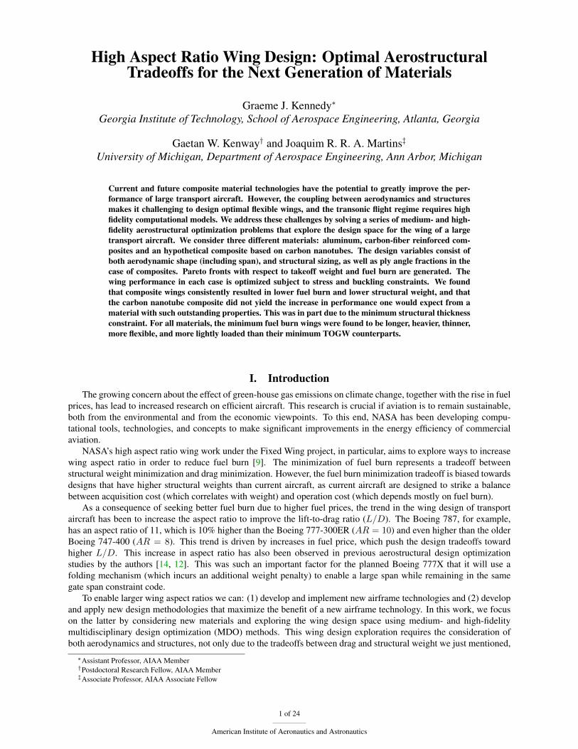
III. The QCRM wingFor this study we created a wing based on the common research model (CRM) configuration used in the DPW 4
and 5 workshops [32], which we call the Quasi-CRM (QCRM) wing. The QCRM is a wing and wing-tail geometrythat has a planform that is roughly the same as the CRM, but the QCRM geometry is not directly derived from theCRM wing.
The QCRM wing has several advantages over the CRM wing for parametric design studies. The QCRM is basedon the jig shape of the wing and does not implicitly assume any aeroelastic deflection, as the CRM geometry does. Thisgreatly simplifies aerostructural design studies, since the wing deflections do not have to be removed from the winggeometry. In addition, the QCRM geometry has a simple parametric description, and as a result, the wing planformcan easily be manipulated using a small number of geometric design variables. Since the QCRM wing is untwisted,the aerodynamic performance of the wing will be poor. However, we always compare the performance of optimizeddesigns so the initial planform and twist distributions are unimportant.
Figure 1: The Quasi-CRM (QCRM) wing geometry is based on the CRM planform and was created to facilitateaerostructural design optimization studies.
The QCRM wing is shown in Figure 1. The QCRM wing is untwisted, has a root chord of 12 m, a tip chordor 2.75 m, a semi-span of 30 m and a quarter-chord sweep of 35◦. The leading edge of the wing is straight, whilethe trailing edge of the wing is quadratically interpolated between the root trailing edge and the tip. The trailingedge is determined using a quadratic spline where a control point is added at a span-wise location of 10.5 m, with achord of 6.5 m. The curved trailing edge corresponds roughly with a wing crank, but is entirely smooth. The wing isconstructed using a set of lofted super-critical NASA SC(2)-0414 and SC(2)-0610 airfoil sections. While the initialaerodynamic performance of this wing is poor, we do not use its initial performance as a baseline. Instead, we onlycompare optimized designs.
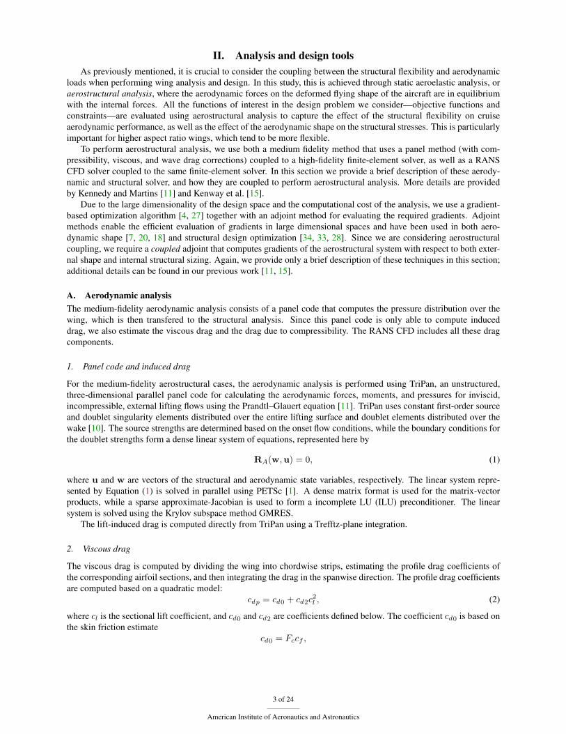
The internal wing structure geometry is shown in Figure 2. The wing box structure consists of two structuralspars and 44 ribs as well as top and bottom wing skins. In addition, non-structural elements are added to the modelto improve the load and displacement transfer between the aerodynamic and structural models. These non-structuralelements consist of the leading edge skin and a false trailing edge spar and skin that extend behind the true trailingedge spar. A more detailed wing model could include the control surfaces and leading and trailing edge supportstructures. However, fully modeling these additional features is not considered here due to the additional complexity.Furthermore, it would be necessary to add additional load cases to the design problem to properly size these portions ofthe structure, complicating the design problem formulation. We have also experimented with the complete omission ofthe leading and trailing edge surfaces, but this leads to difficulties, as the structural displacements must be extrapolatedto the aerodynamic surface. When the structural and aerodynamic surfaces are far apart, the extrapolation of thedeformed aerodynamic surface becomes inaccurate, and maintaining a smooth deformed surface can be difficult. As
6 of 24
American Institute of Aeronautics and Astronautics
Figure 2: The QRM structural wing box model includes spars, ribs, and skins with smeared stiffeners.
a result, we include these non-structural elements as a compromise. One of the primary purposes of the structuralmodel is to provide an accurate weight estimate based on the primary structure within wing. Therefore, we omit thenon-structural components from the weight estimate and set them with a minimum thickness determined by the parttype, which is described in more detail below. Furthermore, we reduce the stiffness of these components and maintaina consistent Poisson’s ratio to avoid stress concentration effects.
Within the wing box, the first 3 ribs in the structure are parallel to the symmetry plane. This section of the wingbox lies within the fuselage and is designed to model the center wing-box. The leading and trailing edge spars lie at15% and 65% of the local chord, respectively, while the non-structural trailing edge extends to 90% of the chord. Thestructural finite-element model used for both low and high-fidelity analysis consists of 31,130 third order MITC9 shellfinite-elements with 131 630 nodes and roughly 789 780 degrees of freedom.
IV. Structural design parametrizationsThe parametrization of the structural design defines the design variables that the optimization algorithm can con-
trol. In this section, we present the structural parametrizations for the metallic, composite and CNT-based compositewings. We model the structure using a smeared stiffness approach. In the smeared stiffener approach the effect of thestiffeners on the stiffness of the panels is included in the material properties of the panel directly rather than modelingeach discrete stiffener individually. This approach works well when the ratio of the panel side-length to stiffener pitchis high, such that there is a high density of stiffeners [30]. Furthermore, the smeared stiffener approach reduces themesh spacing requirements significantly compared to a discrete stiffener techniques, greatly reducing computationalcosts associated with the structural analysis.
In the structural parametrization for the metallic, composite and CNT-based composite wings, we split the wingstructure into approximately flat panels that are analyzed and designed based on the stress state in the global finite-element model under a series of loading conditions. These panels consist of the structural components formed betweenthe ribs and spars of the wing. In order to obtain an accurate estimate of the overall wing-box weight it is necessaryto have a design tool that can correctly size panels over a wide range of loading conditions. The panels range fromrelatively lightly loaded at the tip to heavily loaded at the wing root. Over this range, it is most important to capture thebehavior of the heavily loaded parts of the structure, since these structural components will have the greatest impacton the structural wing weight.
For the present work, we developed a design tool that predicts the stiffness of the panel based on a smeared-stiffener approach. This tool can also be used to enforce strength, buckling, and manufacturing constraints, as well asadjacency constraints that impose limits on the variation of the design variables between adjacent panels. The sizingof the panel is based on the simplified stiffness calculations and buckling criteria proposed by Stroud and Agranoff[30].
To avoid some of the more challenging aspects of composite design problems, we do not design the exact stackingsequence of the structure [13, 12]. Instead, we obtain an approximate design based on the fractions of plies at givenangles. Here, we restrict the possible ply angles to 0◦, ±45◦ and 90◦, where we enforce a balanced laminate byrequiring that the ply fractions of the positive and negative 45◦ plies are equal. The in-plane strength and stiffnesscan be determined exactly using the ply fraction variables alone [8]. However, the bending stiffness, bending strength,
7 of 24
American Institute of Aeronautics and Astronautics
and buckling characteristics of the laminate cannot be determined exactly without knowledge of the laminate stackingsequence. Instead we use conservative estimates of the exact quantities, where possible. Most importantly, theseformula approach the exact formula for very thick panels.
1. Smeared panel stiffness calculations
The ply fractions of the skin-panel are denoted f (p)i , while the ply fractions in the stiffener are denoted f (s)i . Thestiffness of the panel and stiffener are based on a stiffness weighted by the ply fractions:
Q(p) =
4∑i=1
f(p)i Q(θi), Q(s) =
4∑i=1
f(s)i Q(θi),
where θi = {−45o, 0o, 45o, 90o}, Q(θ) is the stiffness in the global axis, and Q(p) and Q(s) are the weighted stiffnessof the skin and stiffener, respectively. Note, that ply fractions are not independent, and must satisfy the followinglinear constraints:
4∑i=1
f(p)i = 1,
4∑i=1
f(s)i = 1.
The stiffness of the overall panel is determined by accounting for the effect of the discrete stiffeners by addingadditional bending and shear stiffness to the skin stiffness. The panel stiffness can be determined based on the panelthickness tp, the stiffener height hs, the stiffener width tw, the stiffener pitch sp, and the stiffness of the skin andstiffener Q(p) and Q(s). The smeared panel stiffness matrices are written as follows:
A = tpQ(p) + A(s), B = B(s),
D =t3p12
Q(p) + D(s), As = A(p)s + A(s)
s .(12)
The non-zero components of the matrices A(s), B(s), D(s), and A(s)s are:
A(s)11 =
EsAs
sp, B
(s)11 = − hs
2spEsAs,
D(s)11 =
Es(h2sAs + 4Is)
4sp, A(s)
s 11 =5GsAs
6sp,
where, Es = Qs11 −
Qs21Q
s12
Qs66
is the extension modulus of the stiffener, As is the area of the stiffener, and Is is the
second moment of area of the stiffener.
2. Panel-level failure analysis
Each panel in the structure must be constrained such that the response under each loading condition lies within anallowable operational envelope. In this study, we impose this envelope by considering both failure constraints andbuckling constraints. For the metallic cases, the failure envelope is modeled using a von Mises stress failure criterion,while for the composite and CNT-based composite cases, the failure envelope is calculated based on a maximum strainfailure criterion. This maximum strain failure criterion can be written as follows:
max
{ε1ε1t
,ε1ε1c
,ε2ε2t
,ε2ε2c
γ12γ12s
, − γ12γ12s
}(13)
where ε1, ε2 and γ12 are the normal, transverse and engineering shear strains in the local ply axis. The constants ε1t ,ε1c are the maximum allowable tensile and compressive strains along the fiber direction, while ε2t and ε2c are themaximum tensile and compressive strains in the transverse directions, and γ12s is the maximum in-plane shear strainallowable. This failure criteria is applied at all ply angles for the outer-most fibers in the skin, and the lowest fiberin the stiffener. This results in 12 separate failure criteria for each point in the panel where the failure constraint isapplied.
8 of 24
American Institute of Aeronautics and Astronautics

3. Panel-level buckling analysis
The buckling constraints are imposed by constraining several independent buckling modes including buckling of theskin between stiffeners, buckling of the stiffeners, and overall panel buckling including stiffeners and skins. The overallcritical buckling loads are determined based on the approach of Stroud and Agranoff [30]. The skin and stiffenerbuckling loads are determined by assuming that the panel ends are simply supported along the lines of attachmentwith adjacent structural components. The critical loads are determined under the assumption that the panels are nearlyflat, and therefore the analysis ignores any curvature effects.
We assume that the interaction between the longitudinal and shear buckling modes collapses into the followingbuckling envelope:
B(N1, N12) =N2
12
N212,cr
+N1
N1,cr≤ 1, (14)
where N1 and N12 are the longitudinal and shear loads respectively and N1,cr and N12,cr are the critical longitudinaland shear buckling loads. Note that N1 and N12 are computed in a locally aligned panel axis. Equation (14) is appliedseparately to the overall panel buckling, stiffener buckling and inter-stiffener skin buckling. The critical loads, N1,cr
and N12,cr are determined based on the formula presented in Table 1.
Overall buckling Skin buckling
N1,crπ2EIsspL2
x
2π2
s2p
(√D11D22 +D12 + 2D66
)EIs = z2n(tpspEp + tshsfbEs) + Es
(tsh3s12
+ tshs
(zn −
hs2
)2)
zn =Cn
AnCn = Es
h2s2ts An = Epsptp + Eshsts(1 + fb)
N12,cr ξ =
√D1D2
D3ξ =
√D11D22
D12 + 2D66
If ξ > 14
L2x
(D31D2)0.25
(8.125 +
5.045
ξ
)4
s2p(D11D
322)0.25
(8.125 +
5.045
ξ
)If ξ ≤ 1
4
L2x
√D1D3(11.7 + 0.532ξ + 0.938ξ2)
4
s2p
√D22(D12 + 2D66)(11.7 + 0.532ξ + 0.938ξ2)
Table 1: A summary of the critical load computations for the overall and skin buckling constraints. Note that An
and Cn are the modulus-weighted zeroth and first moments of area of the panel and stiffener, and zn is the modulus-weighted centroid. The bending stiffness EIs can then be used to determine the critical buckling load.
b
wb
hs
tstb
tw
Figure 3: The panel geometry and thickness design variables used in the structural design parametrization.
9 of 24
American Institute of Aeronautics and Astronautics

V. Aerostructural design optimization formulationThe aerostructural design optimization problem is solved using the multidisciplinary feasible MDO architec-
ture [24], whereby each design iteration is feasible with respect to the coupled governing equations, and all designvariables are optimized simultaneously in a monolithic fashion. In the aerostructural design problem, we implementeda representative aircraft design problem formulation that captures the most essential aspects of the aircraft designproblem in order to quantify the tradeoff between aerodynamic performance and structural weight reduction. This isessential in order to make a fair comparison between potential benefits of candidate structural technologies.
In this design formulation, we minimize a weighted combination of fuel burn and take-off gross weight (TOGW)for a single long-range high-payload mission. We compute the fuel consumption of the mission using the Breguetrange equation:
FB = LGW(
exp
(RTSFCV (L/D)
)− 1
), (15)
where FB is the fuel burn for the entire mission, LGW is the landing gross weight of the aircraft (which is the sumof the reserve fuel and the zero fuel weight of the aircraft), R is the mission range, TSFC is the thrust-specific fuelconsumption, V is the cruise speed, and L/D is the lift-to-drag ratio.
Due to aerostructural effects, the deformed flying shape, and aerodynamic performance of the wing changes withaircraft weight, and thus L/D varies during the mission, even at a fixed lift coefficient. A more accurate analysiswould integrate the true aircraft L/D over the mission profile using the Breguet range integral. In this work, however,we neglect these aerostructural effects and instead evaluate the L/D of the aircraft at the half fuel weight condition.Note that this is not the same point as the mid-range point.
To compare the impact of structural weight reduction and fuel burn reduction, we utilize a composite objectivethat includes both takeoff gross weight and fuel consumption. This provides a more realistic range of designs than themore extreme discipline-level objectives of structural weight and aerodynamic drag. The composite objective can bewritten as follows:
f(x) = βFB + (1− β)TOGW, (16)
for β ∈ [0, 1]. Note that since the TOGW is the sum of the landing gross weight (LGW) and the fuel burn, thisobjective is equivalently f(x) = (2−β)FB+(1−β)LGW. Alternatively, using Breguet range equation, the objectivecan be written as follows:
f(x) = LGW(
exp
(RTSFCV (L/D)
)− β
). (17)
A. Aerostructural optimization problem description1. Objective function
The aircraft sizing parameters are based roughly on a next-generation 777-sized aircraft. In an effort to simplify thedesign problem, only a wing is modeled and constant drag factors are used to estimate the drag of the remainingaircraft components.
We estimate the landing weight, LGW, at the end of the cruise segment using the following expression:
TOGW = OEWfixed +K1 ×Mstruct +K2 ×Aplanform +Mreserve +Mpayload (18)
The OEWfixed is derived from the preliminary aircraft design structural weight breakdown given by Kroo [16].For the metallic design this results in a fixed OEW of 98 700 kg. For the composite and CNT designs, we assumed aweight savings of 30% for the fuselage, horizontal stabilizer and vertical stabilizer and this results in a fixed OEW thatis 10 500 kg lower than the metallic case, or OEWfixed = 88 200 kg.
The structural mass, Mstruct, is evaluated directly from the finite-element model. A mark-up factor K1 = 1.5is applied to account for additional fastener weight and structural component that are absent from the finite-elementmodel. There is an additional contribution, K2 × Aplanform which is designed to account for the weight contributionsfrom the leading and trailing edge wing structures. For the optimization presented, we use K2 = 15 kg/m2.
The reserve fuel is calculated based on a 45 minute loiter at sub-optimalL/D and TSFC conditions, and a diversionto an alternate airport 500 nm away. For simplicity, the resulting reserve fuel quantity, 14 100 kg, remains fixedthroughout the optimization.
The cruise mission uses the maximum payload, maximum range mission for the 777-200ER aircraft. The maxi-mum payload is set at 55 000 kg and the mission range is 6 000 nm. The L/D performance of the aircraft is evaluatedat the point in the mission where half of the mission fuel has been consumed. To account for the drag on the fuselage,
10 of 24
American Institute of Aeronautics and Astronautics

horizontal stabilizer, vertical stabilizer and nacelles, a constraint drag factor of 0.0100 is added the total drag computedon the QCRM wing geometry:
L
D=
CL
CD + 0.0100(19)
A summary of the relevant parameters is given in Table 2.
Parameter Value
Fixed O.E.W. (metallic) 98 700 kgFixed O.E.W. (composite) 88 200 kgK1 1.5K2 15 kg/m2
Reserve Fuel 14 100 kgPayload 55 000 kgRange 6 000 nmAnalysis altitude 36 000 ftMach 0.85Span 60 mCD0
0.0100Root chord 12 mTip chord 2.75 mLeading Edge Sweep 37.2◦
Sref 397.46 m2
Maneuver Altitude 12 000 ftManeuver Mach 0.75
Table 2: Parameters used for the aircraft design problem.
Table 3 shows the properties of the materials used in this study including the metallic, composite and CNT-basedcomposite. Note that the hypothetical CNT-based composite material is based on a tensile modulus of 1.2 TPa anda tensile strength of 6 GPa, while the remaining properties are scaled to match the corresponding composite materialdata. A composite material with such properties is currently in the realm of science fiction, but we use it here toquantify the impact on wing design of improving material properties by an order of magnitude.
2. Design Constraints
The optimization problems presented require a variety of constraints to ensure a physically meaningful designs.For the aerostructural problem, we use a series of failure and buckling constraints that are imposed at two critical
points within the design envelope. These are the 2.5 g and−1 g points shown in the V-n diagram of Figure 4. For boththe failure and buckling constraints we employ a Kreisselmeier-Steinhauser (KS) aggregation technique [28], wherewe group point-wise constraints from within each element into a small number of global constraints. The KS functioncan be written as follows:
KS = cmax +1
ρKSln
[N∑i=1
exp(ρKS(ci − cmax))
], (20)
where ci are all the point-wise failure or buckling constraints in the aggregation domain, cmax = max{c1, c2, . . . , cN}is the maximum value of the failure or buckling constraint, and ρKS is a penalty parameter that we set to 80.0 in allcalculations presented here. Since the KS function is conservative, if the failure envelope of the KS function is notviolated, then none of the individual element-wise failure functions is violated. Instead of aggregating all the failureand buckling functions into a single constraint, we group the failure and buckling constraints separately over commonstructural components. We separate the top and bottom wing skins, respectively and group all spars and ribs into asingle KS constraint. Since we do not utilize buckling constraints for the spars and ribs, there are only two KS bucklingconstraints, while there are three KS failure constraints for each structural load condition.
11 of 24
American Institute of Aeronautics and Astronautics

Parameter Value Units Parameter Value Units
Aluminum material data
E 70.0 GPa ν 0.3σY S 420 MPa ρ 2780 kg/m3
Composite material data
E1 128 GPa E2 11 GPaG12 4.5 GPa G13 4.5 GPaG23 3.2 GPa ν12 0.25Xt 1170 MPa Xc 1120 MPaYt 40 MPa Yc 170 MPaS 48 MPa ρ 1522 kg/m3
Carbon nanotube-based composite material data
E1 1200 GPa E2 120 GPaG12 45 GPa G13 45 GPaG23 32 GPa ν12 0.25Xt 6000 MPa Xc 5000 MPaYt 400 MPa Yc 1600 MPaS 500 MPa ρ 1522 kg/m3
Table 3: Mechanical properties of the metallic, conventional composite and hypothetical CNT-based composite usedin this study.
3. Design Variables
The design variables consist of geometric variables, structural variables, aerodynamic design variables and consistencyvariables. The aerodynamic design variables consist of the angles of attack at each of the cruise and maneuver condi-tions. However, to avoid inconsistencies resulting from both root twist and angle of attack, the cruise alpha remainsfixed.
For the TriPan analysis, the geometric variables consists of 8 twist variables distributed along the wing span, onespan-scaling variable, and one chord scaling variable and 8 vertical scaling variables, which modify the thicknessto chord ratio. Together the span and chord scaling variables admit a series of planforms that are stretched in thechord-wise and span-wise directions, but share similar geometric features.
For the CFD-based design optimization, the same twist, span and chord variables are used, and 192 airfoil shapevariables are added. The shape variables control the airfoil shapes and permit arbitrary thickness distributions in boththe chord and spanwise direction, and thus the vertical scaling variables used with TriPan are not required. A view ofthe free form deformation volume used for the CFD-based design optimization is given in Figure 5.
The structural design variables are the same for both the low and high fidelity analysis. Two variables determinethe stiffener pitch of the entire upper and lower skins, respectively. Each panel formed by the leading edge, trailingedge, and ribs is assigned the variables shown in Figure 3. Each panel has two thickness variables for the skin andstiffener, respectively, as well as a panel height. The stiffener base width is fixed based on the stiffener height. Forthe metallic cases, no further information is necessary. For the composite and CNT designs there are three additionalvariables that define the ply-fraction for the skin. In this work, we fix the ply-fractions within the stiffeners to a 0o-plydominant laminate.
There are several consistency variables that are required in the design problem. First, we add a fuel mass consis-tency variable for each of the 4 missions. These variables are used in the application of the inertial relief from thefuel loads. They ensure that a fraction of the total fuel load is applied to the wing. In addition, we add an equivalentfuel traction on either the top or bottom skins for each maneuver load. These loads correspond to the surface forceper-unit-area exerted by the fuel on the wing. We add a consistency variable for each rib-bay for the entire wing.Finally, for the buckling constraints, it is necessary to have an equivalent panel length, since this information cannotbe calculated for each element, we add a length variable for each panel in the wing. We then add a geometric constraintthat the physical panel length must match the panel length variable for each component of the wing.
12 of 24
American Institute of Aeronautics and Astronautics

-1
0
1
2
2.5
3
Load factor
Equivalent air speed
VDVS VA
CL = CLmax
2.5g stall 2.5g dive
-1g dive
Figure 4: V-n diagram showing the critical points where the structural constraints are imposed.
Figure 5: The design variables for the CFD-based design optimization are the vertical positions of 192 points thatcontrol the wing shape through a free form deformation (FFD) volume.
4. Optimization Problem Statement
The aerostructural optimization problem can now be summarized as follows: The objective is to minimize a linearcombination of the TOGW and fuel burn by varying the external shape variables and structural sizing variables de-scribed above, as well as the ply fractions when the material is a composite. Simultaneously, the structural designmust satisfy a series of failure and buckling constraints at the two off-design conditions shown in Figure 4 such thatthe three KS failure constraints and two KS buckling constraints at each maneuver load are within the admissiblefailure envelope. In addition, we impose steady-state lift and trim constraints at each of the 3 operating conditions.
13 of 24
American Institute of Aeronautics and Astronautics

The aerostructural optimization problem can be written as follows:
minimize βFB + (1− β)TOGWw.r.t. x
such that KS(i)fail ≤ 1 i = 2, . . . , 3
KS(i)buckling ≤ 1 i = 2, . . . , 3
L(i) = n(i)W (i) i = 1, . . . , 3
c(x) = 0
l ≤ Ax ≤ u
(21)
where KS(i)fail and KS(i)
buckling are the KS failure and KS buckling constraints, L(i) = n(i)W (i) and is the lift constraint foreach analysis condition, and n(i) is the load factor, c(x) = 0 represents all the consistency constraints and l ≤ Ax ≤ urepresents the adjacency constraints. Note that the consistency constraints are nonlinear but do not depend on thesolution of the aerostructural problem directly, therefore their derivatives are inexpensive to evaluate.
VI. Results and DiscussionIn this section, we present the results from a series of optimizations for the metallic, conventional composite and
CNT-based composite wings. We present results for both the medium- and RANS-based high-fidelity aerostructuraloptimization. The conclusions drawn from both sets of optimizations are helpful in assessing the impact of struc-tural technologies on the tradeoff between structural weight reduction and drag minimization. As part of this study,we present a series of optimizations with different values of the parameter β using the aerostructural design formu-lation (21). In addition, we compare the fully integrated designs we obtain with the full aerostructural optimizationframework, to a sequential design approach. In the sequential approach, we repeatedly perform design iterations wherethe structure is sized at fixed aerodynamic loads to obtain a structural weight estimate, followed by an aerodynamicoptimization at fixed structural weight to minimize the fuel burn. This design process ignores the impact of aeroelasticdeformation, but provides a useful comparison of the fully integrated optimization approach with a sequential designmethod.
A. Medium-fidelity aerostructural optimizationFirst, we present the results from the aerostructural optimization framework that uses the panel-method aerodynamicswith empirical profile and wave drag corrections. The results from this study help inform the interpretation of the fullRANS-based high-fidelity aerostructural optimization results and provide insight into the most important aspects ofthe problem.
Figure 6 shows the planforms of the aerostructural optimization results for the metallic, conventional compositeand CNT-based composite designs. Both the metallic and conventional composite designs are shown for β = 0, 0.5,0.625, 0.75, 0.875, and 1, while the CNT-based results are shown for β = 0, 0.5, 0.75, and 1. For all designs the spansincrease monotonically as β increases. This trend reflects the increasing importance placed on fuel burn reduction asreflected in the objectives for larger values of β. While all designs exhibit increasing aspect ratios, the aspect ratiosfor the conventional composites and CNT-based composites, are higher than conventional aircraft.
Figure 7 shows the Pareto fronts for the designs obtained from the aerostructural optimization with the variousvalues of β. Recall that β = 0 corresponds the a TOGW minimization, β = 1 corresponds the a fuel burn minimiza-tion, and intermediate values represent a compromise between these two objectives. Figure 7 also show the resultsfrom a sequential design method for a series of fixed spans with metallic wings. As we can see, there is a significantdifference between the performance of the wing obtained from a sequential design method and the aerostructural op-timization results. The performance for the sequential designs is predicted using aerodynamic analysis only, withoutthe impact of aeroelastic optimization. Therefore, the actual performance of the designs will be different than what isshown here. We are currently working to refine the sequential design method in order to better reflect current indus-trial practice. The sequential designs exhibit higher takeoff gross weights than all but the β = 1 aerostructural fuelburn optimization. These sequential optimization results are in agreement with previous low-fidelity aerostructuraloptimization results, where the sequential approach was shown to be inferior relative to the MDO approach [5, 3]. Thepresent study is the first such comparison for higher-fidelity models, and it is also the first comparison of a Pareto frontobtained from sequential optimization.
14 of 24
American Institute of Aeronautics and Astronautics

0 5 10 15 20 25 30 35 40 45 50 55 60 65 70
0 5 10 15 20 25 30 35 40 45 50 55 60 65 70
0
5
10
15
20
25
30
35
40
45
50
0
5
10
15
20
25
30
35
40
45
50
MetallicComposite
CNT
Figure 6: The planforms for the metallic, conventional composite and CNT-based composite wings show thataerostructurally optimal spans increase as the material properties improve.
From the Pareto front trends shown in Figure 7 it is clear that the use of advanced materials leads to simultaneousfuel burn and structural weight improvements. As more advanced materials are used, the difference in performancebetween fuel burn minimization and TOGW minimized designs becomes smaller and the Pareto fronts become morecompact. This is due to the larger weight savings, which reduces both fuel consumption and TOGW directly. Thecomposite TOGW design (β = 0) is 8.4% lighter than the metallic baseline, and the CNT-based composite design is5.6% lighter relative to the β = 0 composite design. For the fuel burn optimized designs (β = 1) the composite designexhibits a 7.7% fuel burn advantage compared to the metallic design, and the CNT-based composite exhibits a further5.2% fuel burn reduction compared to the composite β = 1 design. Thus, the improvements in performance of theCNT-based composite wings are relatively modest compared to the drastically improved performance assumed in thematerial properties. This is in part because the weight savings were limited by minimum thickness constraints, as wewill see later.
Figure 8 shows the fuel burn and TOGW as a function of span for the metallic, conventional composite and CNT-based composite designs, as well as the sequential design optimization method. The fuel burn optimized designsexhibit large spans (all greater than 80 m) at the cost of increased wing structural weight, which explains the TOGWtrend. The combination of the fuel burn and TOGW trend with span demonstrate the key tradeoff that makes aerostruc-tural design optimization so challenging: The objective function is very flat with respect to span, since the changesin structural weight are balanced by the induced drag [17]. A flat objective function makes it difficult to differentiatebetween designs with different spans, and numerical issues arise when using optimization to find the best design.
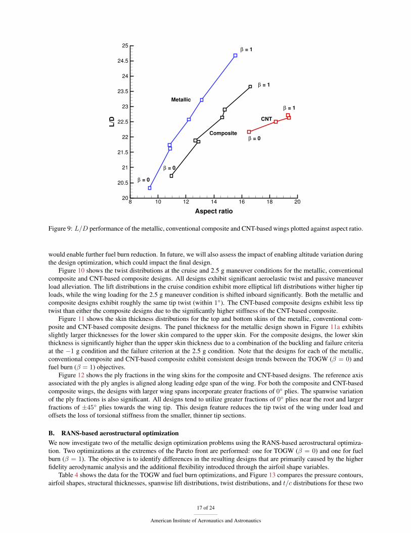
Figure 9 shows the cruise L/D as a function of the aspect ratio for the metallic, conventional composite, and CNT-based composite designs. The metallic designs exhibit aspect ratios between 9.4 and 15.5, the conventional compositedesigns exhibit aspect ratios between 10.9 and 16.5, and the CNT-based composite wings exhibit aspect ratios between16.6 and 19.5. The RANS-based high-fidelity wing results exhibit aspect ratios of around 11. Nearly all the mediumfidelity results exhibit the same trend: increasing aspect ratio and L/D as more emphasis is put on minimizing fuelburn (increasing β). Another key trend is the variation of cruise L/D both with fixed structural technology and be-tween different structural technologies. The cruise L/D increases monotonically for fixed wing construction as moreemphasis is put on minimizing fuel burn. This is expected since fuel burn reduction can be achieved by increasing theL/D at cruise. However, between different structural technologies, the cruise L/D decreases, despite the significant7.7% and 5.4% fuel burn reductions between the metallic and composite, and composite and CNT designs shown in
15 of 24
American Institute of Aeronautics and Astronautics

Metallic
Composite
CNT
β = 0
β = 1
β = 0.75
β = 0
β = 1
8.4 %
5.6 %
7.7 %
5.2 %
Metallic sequential
Takeoff gross weight [kg]
Fu
el b
urn
[k
g]
240000 260000 280000 300000
57500
60000
62500
65000
67500
70000
72500
75000
77500
Figure 7: The Pareto fronts of fuel burn and takeoff gross weight shows the advantage of the conventional com-posite and CNT composite materials, as well as the advantage of aerostructural design optimization over sequentialoptimization.
β = 0β = 1
β = 0
β = 0
β = 1
β = 1Metallic
Composite
CNT
Metallic sequential design
Span [m]
Fu
el b
urn
[k
g]
60 65 70 75 80 85 90 95 100
55000
60000
65000
70000
75000
80000
β = 0β = 1
β = 0
β = 0
β = 1
β = 1
Metallic
Composite
CNT
Metallic sequential design
Span [m]
Ta
ke
off
gro
ss
we
igh
t [k
g]
60 65 70 75 80 85 90 95 100
230000
240000
250000
260000
270000
280000
290000
300000
310000
320000
Figure 8: The fuel burn and MTOW as a function of the span for the metallic, conventional composite and CNT-basedcomposite wings.
Figure 7. A preliminary analysis of the results suggests that further fuel burn reductions could be achieved by allowingthe designs with larger wing areas to fly at higher altitudes wither more optimal L/D values. This altitude variation
16 of 24
American Institute of Aeronautics and Astronautics
Metallic
Composite
CNT
β = 1
β = 0
β = 0
β = 1
β = 0
β = 1
Aspect ratio
L/D
8 10 12 14 16 18 2020
20.5
21
21.5
22
22.5
23
23.5
24
24.5
25
Figure 9: L/D performance of the metallic, conventional composite and CNT-based wings plotted against aspect ratio.
would enable further fuel burn reduction. In future, we will also assess the impact of enabling altitude variation duringthe design optimization, which could impact the final design.
Figure 10 shows the twist distributions at the cruise and 2.5 g maneuver conditions for the metallic, conventionalcomposite and CNT-based composite designs. All designs exhibit significant aeroelastic twist and passive maneuverload alleviation. The lift distributions in the cruise condition exhibit more elliptical lift distributions wither higher tiploads, while the wing loading for the 2.5 g maneuver condition is shifted inboard significantly. Both the metallic andcomposite designs exhibit roughly the same tip twist (within 1◦). The CNT-based composite designs exhibit less tiptwist than either the composite designs due to the significantly higher stiffness of the CNT-based composite.
Figure 11 shows the skin thickness distributions for the top and bottom skins of the metallic, conventional com-posite and CNT-based composite designs. The panel thickness for the metallic design shown in Figure 11a exhibitsslightly larger thicknesses for the lower skin compared to the upper skin. For the composite designs, the lower skinthickness is significantly higher than the upper skin thickness due to a combination of the buckling and failure criteriaat the −1 g condition and the failure criterion at the 2.5 g condition. Note that the designs for each of the metallic,conventional composite and CNT-based composite exhibit consistent design trends between the TOGW (β = 0) andfuel burn (β = 1) objectives.
Figure 12 shows the ply fractions in the wing skins for the composite and CNT-based designs. The reference axisassociated with the ply angles is aligned along leading edge span of the wing. For both the composite and CNT-basedcomposite wings, the designs with larger wing spans incorporate greater fractions of 0◦ plies. The spanwise variationof the ply fractions is also significant. All designs tend to utilize greater fractions of 0◦ plies near the root and largerfractions of ±45◦ plies towards the wing tip. This design feature reduces the tip twist of the wing under load andoffsets the loss of torsional stiffness from the smaller, thinner tip sections.
B. RANS-based aerostructural optimizationWe now investigate two of the metallic design optimization problems using the RANS-based aerostructural optimiza-tion. Two optimizations at the extremes of the Pareto front are performed: one for TOGW (β = 0) and one for fuelburn (β = 1). The objective is to identify differences in the resulting designs that are primarily caused by the higherfidelity aerodynamic analysis and the additional flexibility introduced through the airfoil shape variables.
Table 4 shows the data for the TOGW and fuel burn optimizations, and Figure 13 compares the pressure contours,airfoil shapes, structural thicknesses, spanwise lift distributions, twist distributions, and t/c distributions for these two
17 of 24
American Institute of Aeronautics and Astronautics

span [m]
c C
l
0 5 10 15 20 25 30 35 40 45 500
2
4
6
cruise
2.5g maneuver
span [m]
twis
t [d
eg
ree
s]
8
6
4
2
0
2 cruise
2.5g maneuver
β = 0 (TOGW)β = 1 (Fuel burn)
29.6 m 41.5 m
(a) Metallic
span [m]
c C
l
0 5 10 15 20 25 30 35 40 45 500
2
4
6
cruise
2.5g maneuver
span [m]
twis
t [d
eg
ree
s]
8
6
4
2
0
2
cruise
2.5g maneuver
β = 0 (TOGW) β = 1 (Fuel burn)
32 m
42.7 m
(b) Composite
span [m]
c C
l
0 5 10 15 20 25 30 35 40 45 500
2
4
6
cruise
2.5g maneuver
span [m]
twis
t [d
eg
ree
s]
8
6
4
2
0
2
cruise
2.5g maneuver
β = 0 (TOGW)
β = 1 (Fuel burn)
40.8 m 47 m
(c) CNT
Figure 10: Twist at cruise and the 2.5 g maneuver condition, as well as lift normalized by dynamic pressure at thecruise and 2.5 g maneuver conditions.
optimizations. ).The performance of the baseline design was poor due to a large wave drag component and therefore is not used for
comparison purposes. Both the fuel burn and TOGW were reduced for relative to the initial design in both optimiza-tions.
As expected, the TOGW for the β = 0 optimization is lower than the fuel burn optimization, but converse isnot true: The fuel-burn optimized design has 0.7% high fuel burn. The reason for this discrepancy is that theseoptimizations were performed at a fixed altitude, and therefore the wing is not free to fly at the best point in itsdrag polar. For the fuel burn optimization, the final reference area was increased by 35% from the baseline value of198.3 m2. With such a large increase in area, the fixed design altitude of 36 000 ft does not yield the best possibleperformance for the fuel burn optimized design. An altitude sweep was performed at constant lift for each of thetwo optimized designs. For the minimum TOGW design, the best altitude was 36,250 ft, which is close to the designaltitude. However, the minimum fuel burn design, which has a significantly reduced wing loading, benefits from a
18 of 24
American Institute of Aeronautics and Astronautics

β = 0.0
β = 0.5 β = 0.625β = 0.75
β = 0.875
β = 1.0
panel thickness [mm]21.318.716.213.611.18.66.03.5
Upper surface
Lower surface
(a) Metallic
β = 0.0
β = 0.5 β = 0.625
β = 0.75 β = 0.875
β = 1.0
panel thickness [mm]32.028.023.919.815.711.77.63.5
Upper surface
Lower surface
(b) Composite
β = 0.0
β = 0.5β = 0.75 β = 1.0
panel thickness [mm]10.09.18.17.26.35.44.43.5
Upper surface
Lower surface
(c) CNT
Figure 11: Skin thickness distributions for the conventional composite and CNT-based composite designs.
higher altitude, being the best at around 39 000 ft. At this altitude, the fuel burn for the β = 1.0 design is 71 467 kg,3.7% lower than for the β = 0.0. However, even correcting for the best altitude does not ensure that fuel burn designis optimal. This is because the optimization designed the airfoil cross sections for low wave drag at a much lowerCL (for 36 000 ft) than is experienced at 39 000 ft for the same lift. Thus, if large changes in wing area or mass areexpected during the optimization, altitude variation, or a surrogate for altitude variation should be included as a design
19 of 24
American Institute of Aeronautics and Astronautics

β = 0.0
β = 0.5 β = 0.625
β = 0.75 β = 0.875
β = 1.0
ply fraction0 degree fraction
+/- 45 degree fraction
90 degree fraction
Upper surface
Lower surface
(a) Composite
β = 0.0
β = 0.5β = 0.75 β = 1.0
ply fraction0 degree fraction
+/- 45 degree fraction
90 degree fraction
Upper surface
Lower surface
(b) CNT
Figure 12: Ply fractions for the conventional composite and CNT-based composite designs.
β TOGW (kg) Fuel Burn (kg) Wing Mass (kg) L/D Span Wing Area (m2) Aspect Ratio
0.0 268 630 74 242 26 567 20.13 73.8 431.348 12.621.0 290 206 74 754 47 631 21.87 80.8 523.468 12.45
Table 4: TOGW and fuel burn results for RANS-based aerostructural optimization
variable in the optimization problem.The choice of objective function has a dramatic effect on nearly every aspect of the optimized design. The wing
planform is the first major difference (see Figure 13). Both designs have roughly the same aspect ratio, but the fuel burndesign wing span is 7 m longer and has a 21.4% larger wing area. Since th fuel burn objective places less emphasison the empty weight, the wing span extends to lower the span-loading and thus lower the induced drag. This increasein span comes at a substantial penalty in terms of structural weight, 21 064 kg or 79% of the TOGW optimized mass.This large wing mass is further explained by examining the distribution of thickness to chord ratio distributions. Theaverage t/c for the TOGW minimization is 33% higher than for the fuel burn design. However, the difference in thewingbox depth is slightly lower than this due to the larger chord of the minimum fuel burn wing. Further confirmationof the increased wingbox mass can be seen in the upper skin thickness distribution contours in Figure 13. With theexception of the more lightly loaded wing tips, the fuel burn design skin is thicker than the minimum TOGW design.These trends are consistent with previous aerostructural optimizations performed by the authors using Euler CFD [14].
The cruise lift distributions for both minimum fuel burn and minimum TOGW designs shown in Figure 13 areclose to elliptical, but the TOGW design yield a closer match to this ideal distribution. However, there is a very largedifference in the shape of the maneuver lift distributions. Both designs exhibit passive load alleviation—where the2.5 g maneuver lift distribution is shifted inboard relative to the elliptical distribution—but this load alleviation ismore pronounced for the minimum TOGW design.
For the fuel burn design, the corresponding twist distribution shows the additional passive aeroelastic wash-outthat occurs at the maneuver condition. This additional downward twisting reduces the tip load, shifting the distributioninboard and lowering the bending moment on the structure. This behavior is consistent with the medium fidelityresults.
20 of 24
American Institute of Aeronautics and Astronautics

Figure 13: Comparison of TOGW and fuel burn optimized designs
The 2.5 g maneuver lift distribution for the TOGW design shows a completely opposite twist behavior: the wingtwist actually decreases under the higher loading condition. Even so, the maneuver lift TOGW maneuver lift distribu-tion has shifted further inboard and is even more favorable from a structural perspective. To explain this phenomenon,we examined the three-dimensional flow field of the TOGW 2.5 g maneuver condition (shown in Figure 14). Theangle of attack for this simulation is 8.6◦ (3 ◦ larger than the 2.5 g fuel burn case), and a large portion of the winghas stalled, resulting in large region of separated flow. The gray-colored area in Figure 14 is the contour of −0.001x-velocity, showing the region in which the flow direction has reversed. The slice at 66% semi-span shows the theνSA variable, which indicates a region of very large eddy viscosity that is consistent with separated flow. For the fuelburn design, the flow remains attached and the eddy viscosity production is much, much lower. Although stall is notdesirable within the flight envelope (especially tip stall), the optimizer exploited the fact that no stall constraint isimposed to implement an extremely effective way to alleviate the loads. While the simulation of the stalled wing didconverge in the steady state sense, in reality this flow condition is unsteady and would be accompanied by buffeting.Further, such a flow condition would most likely significantly reduce the control effectiveness of any outboard controlsurface.
The “optimal” flow condition for the 2.5 g maneuver condition clearly demonstrates some of the unintended con-sequences of high fidelity aerostructural optimization significant design freedom. Without an explicit stall constraint,the optimizer sees this is a perfectly valid design, that is superior to the bend-twist coupling load alleviation. Wesuspect that this type of design may be an artifact of the single 2.5 g maneuver Mach number and lift coefficient. Otherflow conditions, especially at lower lift coefficient will not be stalled and thus may violate the stress and bucklingconstraints.
VII. ConclusionsIn this paper we investigated the differences between optimal wings for three different materials: aluminum alloy, a
conventional carbon composite and a hypothetical CNT-based composite. The objective was to understand the designtrends for the various materials and to quantify how much the performance can be improved. In the particular caseof the CNT composite, we assumed that both stiffness and strength were about one order of magnitude greater thanconventional composites, which is well beyond what is currently possible. We quantified the potential benefits of the
21 of 24
American Institute of Aeronautics and Astronautics

Figure 14: Flow visualization for the 2.5 g maneuver conditions.
various materials by obtaining Pareto fronts with respect to fuel burn and TOGW, since the real objective function inaircraft design is somewhere between these two objective functions, but depends on a number of factors such as fuelprice.
The design optimization approach was to perform aerostructural optimizations whereby the structural sizing andthe aerodynamic shape are optimized simultaneously. We showed that the Pareto front obtained through aerostructuraloptimization was significantly better than the sequential results with respect to both objectives. The designs obtainedthrough aerostructural optimization exhibited spanwise lift distributions that were close to elliptical at the cruise flightconditions, while being able to take advantage of passive load alleviation at the critical structural load conditions.Thus, an aerostructural optimization approach is essential to obtain optimal static aeroelastic tailored wings and toevaluate the benefits of different materials.
The use of more advanced materials enabled reductions in both objectives, resulting in a movement of the Paretofront towards the origin. The minimum fuel burn composite wing reduced the fuel burn by 7.7% when comparedto the corresponding metallic wing, and the minimum TOGW composite wing reduced the TOGW by 8.4%. Thecorresponding gains for the CNT composite versus the conventional composite wing were more modest: 5.2 and5.6%, respectively. This seems to be mostly due to the minimum structural thickness constraint, which was activefor a large portion of the CNT wing. Since we use the same minimum thickness as the conventional composite, thisminimum value requires further investigation.
The optimal wing trends were consistent among the different materials: the minimum fuel burn wings were foundto be longer, heavier, thinner, more flexible, and more lightly loaded than their minimum TOGW counterparts. Theoptimal composite wings exhibited larger spans than the metallic wings, and the CNT wings had even larger spans,reaching a maximum of almost 97 m for the minimum fuel burn case.
In addition to the aerostructural optimizations based on panel code aerodynamics, we also performed a few RANS-based aerostructural optimizations. While the trends shown by these higher fidelity results were similar, the fuel burnand TOGW values were quite different, and the resulting spans varied a lot less. These differences were in part due toan offset in the drag due to the physics considered, but we also found that some of the optimal wings were not flyingat their optimal lift coefficient. To address this, we plan to include the cruise altitude as an additional design variable.
The RANS results also added an additional insight to this study. The passive load alleviation that we had observedso far consisted in exploiting the bend-twist coupling to twist down the outer wing at the critical load conditionsto reduce the lift in that area, resulting in a reduction in bending moments. However, the RANS result for optimalTOGW discovered it could stall the outer wing to achieve even more dramatic load alleviation. This is obviously nota desirable flight condition and points out the need to enforce a stall constraint in our optimizations.
22 of 24
American Institute of Aeronautics and Astronautics

VIII. AcknowledgmentsFunding for this research was provided by NASA under grant number NNX11AI19A. The authors would like to
thank Christine Jutte, Bret Stanford, and Karen Taminger for their help in defining this project and for their suggestionsin the writing of this paper.
References[1] S. Balay, W. D. Gropp, L. C. McInnes, and B. F. Smith. Efficient management of parallelism in object oriented numerical
software libraries. In E. Arge, A. M. Bruaset, and H. P. Langtangen, editors, Modern Software Tools in Scientific Computing,pages 163–202. Birkhauser Press, 1997.
[2] S. Brown. Displacement extrapolation for CFD+CSM aeroelastic analysis. In 38th Structures, Structural Dynamics, andMaterials Conference, April 1997. doi:10.2514/6.1997-1090. AIAA97-1090.
[3] I. R. Chittick and J. R. R. A. Martins. An asymmetric suboptimization approach to aerostructural optimization. Optimizationand Engineering, 10(1):133–152, Mar. 2009. doi:10.1007/s11081-008-9046-2.
[4] P. E. Gill, W. Murray, and M. A. Saunders. SNOPT: An SQP algorithm for large-scale constrained optimization. SIAMReview, 47(1):99–131, 2005. doi:10.1137/S0036144504446096.
[5] B. Grossman, R. T. Haftka, P.-J. Kao, D. M. Polen, and M. Rais-Rohani. Integrated aerodynamic-structural design of atransport wing. Journal of Aircraft, 27(12):1050–1056, 1990. doi:10.2514/3.45980.
[6] E. J. Hopkins. Charts for predicting turbulent skin friction from the van Driest method (II). Technical Report TN D-6945,NASA, October 1972.
[7] A. Jameson. Computational aerodynamics for aircraft design. Science, 245:361–371, 1989.
[8] R. M. Jones. Mechanics of Composite Materials. Technomic Publishing Co., 1996.
[9] C. V. Jutte, B. K. Stanford, C. D. Wieseman, and J. B. Moore. Aeroelastic tailoring of the NASA common research model vianovel material and structural configurations. In Proceedings of the SciTech Conference, National Harbor, MD, January 2014.
[10] J. Katz and A. Plotkin. Low–Speed Aerodynamics. McGraw–Hill Inc., 1991.
[11] G. J. Kennedy and J. R. R. A. Martins. Parallel solution methods for aerostructural analysis and design optimization. InProceedings of the 13th AIAA/ISSMO Multidisciplinary Analysis Optimization Conference, Fort Worth, TX, September 2010.AIAA 2010-9308.
[12] G. J. Kennedy and J. R. R. A. Martins. A comparison of metallic and composite aircraft wings using aerostructural designoptimization. In 14th AIAA/ISSMO Multidisciplinary Analysis and Optimization Conference, Indianapolis, IN, Sep. 2012.AIAA-2012-5475.
[13] G. J. Kennedy and J. R. R. A. Martins. A laminate parametrization technique for discrete ply angle problems with manu-facturing constraints. Structural and Multidisciplinary Optimization, 48(2):379–393, August 2013. doi:10.1007/s00158-013-0906-9.
[14] G. K. W. Kenway and J. R. R. A. Martins. Multi-point high-fidelity aerostructural optimization of a transport aircraft config-uration. Journal of Aircraft, 2013. doi:10.2514/1.C032150. (In press).
[15] G. K. W. Kenway, G. J. Kennedy, and J. R. R. A. Martins. A scalable parallel approach for high-fidelity steady-state aeroelasticanalysis and adjoint derivative computations. AIAA Journal, 2012. (In press).
[16] I. Kroo. Aircraft design: Synthesis and analysis, November 2013. URL http://adg.stanford.edu/aa241/AircraftDesign.html.
[17] I. M. Kroo. Drag due to lift: Concepts for prediction and reduction. Annual Review of Fluid Mechanics, 33:587–617, Nov.2000.
[18] Z. Lyu and J. R. R. A. Martins. Aerodynamic design optimization studies of a blended-wing-body aircraft. Journal of Aircraft,2014. (In press).
[19] Z. Lyu, G. K. Kenway, C. Paige, and J. R. R. A. Martins. Automatic differentiation adjoint of the Reynolds-averaged Navier–Stokes equations with a turbulence model. In 21st AIAA Computational Fluid Dynamics Conference, San Diego, CA, Jul2013. doi:10.2514/6.2013-2581.
23 of 24
American Institute of Aeronautics and Astronautics

[20] C. A. Mader and J. R. R. A. Martins. Stability-constrained aerodynamic shape optimization of flying wings. Journal ofAircraft, 50(5):1431–1449, September 2013. doi:10.2514/1.C031956.
[21] C. A. Mader, J. R. R. A. Martins, J. J. Alonso, and E. van der Weide. ADjoint: An approach for the rapid development ofdiscrete adjoint solvers. AIAA Journal, 46(4):863–873, Apr. 2008. doi:10.2514/1.29123.
[22] B. Malone and W. Mason. Multidisciplinary optimization in aircraft design using analytic technology models. Journal ofAircraft, 32(2):431–438, mar-apr 1995. doi:10.2514/3.46734.
[23] J. R. R. A. Martins and J. T. Hwang. Review and unification of methods for computing derivatives of multidisciplinarycomputational models. AIAA Journal, 51(11):2582–2599, 2013. doi:10.2514/1.J052184.
[24] J. R. R. A. Martins and A. B. Lambe. Multidisciplinary design optimization: A survey of architectures. AIAA Journal, 51(9):2049–2075, Sep 2013. doi:10.2514/1.J051895.
[25] J. R. R. A. Martins, J. J. Alonso, and J. J. Reuther. High-fidelity aerostructural design optimization of a supersonic businessjet. Journal of Aircraft, 41(3):523–530, 2004. doi:10.2514/1.11478.
[26] J. R. R. A. Martins, J. J. Alonso, and J. J. Reuther. A coupled-adjoint sensitivity analysis method for high-fidelity aero-structural design. Optimization and Engineering, 6(1):33–62, Mar. 2005. doi:10.1023/B:OPTE.0000048536.47956.62.
[27] R. E. Perez, P. W. Jansen, and J. R. R. A. Martins. pyOpt: a Python-based object-oriented framework for nonlinear constrainedoptimization. Structural and Multidisciplinary Optimization, 45(1):101–118, January 2012. doi:10.1007/s00158-011-0666-3.
[28] N. M. K. Poon and J. R. R. A. Martins. An adaptive approach to constraint aggregation using adjoint sensitivity analysis.Structural and Multidisciplinary Optimization, 34(1):61–73, 2007. doi:10.1007/s00158-006-0061-7.
[29] Y. Saad and M. H. Schultz. GMRES: A generalized minimal residual algorithm for solving nonsymmetric linear systems.SIAM Journal on Scientific and Statistical Computing, 7(3):856–869, 1986. doi:10.1137/0907058.
[30] W. J. Stroud and N. Agranoff. Minimum mass design of filamentary composite panels under combined loads: Design pro-cedure based on simplified buckling equations. Technical report, NASA Langley Research Center, Hampton, VA 23665,October 1976.
[31] E. van der Weide, G. Kalitzin, J. Schluter, and J. J. Alonso. Unsteady turbomachinery computations using massively parallelplatforms. In Proceedings of the 44th AIAA Aerospace Sciences Meeting and Exhibit, Reno, NV, 2006. AIAA 2006-0421.
[32] J. C. Vassberg. A unified baseline grid about the common research model wing-body for the fifth aiaa cfd drag predictionworkshop. In 29th Applied Aerodynamics Conference, Honolulu, Hawaii, June 2011. doi:10.2514/6.2011-3508. AIAA2011-3508.
[33] S. Venkatamaran and R. T. Haftka. Structural optimization complexity: what has Moore’s law done for us? Structural andMultidisciplinary Optimization, 28:375–387, 2004.
[34] V. B. Venkayya. Structural optimization: A review and some recommendations. International Journal for Numerical Methodsin Engineering, 13(2):203–228, 1978. doi:10.1002/nme.1620130202.
[35] S. Wakayama and I. Kroo. Subsonic wing planform design using multidisciplinary optimization. Journal of Aircraft, 32(4):746–753, 1995. doi:10.2514/3.46786.
24 of 24
American Institute of Aeronautics and Astronautics