high capacity advancing oil recovery system performance testing at
TRANSCRIPT

High Capacity Advancing Oil Recovery System Performance Testing at Ohmsett for the Wendy Schmidt Oil Cleanup X CHALLENGE
Paul Meyer, Bill Schmidt, Dave DeVitis, and Jane-Ellen Delgado
MAR Incorporated/ Ohmsett Test Facility Atlantic Highlands, NJ, USA
Abstract Ohmsett - The National Oil Spill Response Research & Renewable Energy Test Facility
was selected as the test venue for the $1.4 Million Wendy Schmidt Oil Cleanup X CHALLENGE. The competition was designed to inspire a new generation of innovative solutions for recovering spilled oil from the seawater’s surface.
Ten finalists, selected from more than 350 entries from around the world, demonstrated oil cleanup systems during rigorous testing where they each had 10 days to demonstrate their individual technology in the Ohmsett test tank. In this head-to-head competition, a $1 Million Grand Prize was awarded to the team that demonstrated the ability to recover oil from the water’s surface at the highest oil recovery rate (ORR) at oil recovery efficiency (ORE) of more than 70%.
This was the largest oil recovery test ever conducted at Ohmsett. This paper discusses the test setup and methodology used during the high capacity advancing oil recovery system performance testing at Ohmsett. 1 Introduction
The X PRIZE Foundation, a non-profit organization, selected Ohmsett as the test venue for the $1.4 Million Wendy Schmidt Oil Cleanup X CHALLENGE. This challenge, the Foundation’s sixth major competition, was designed to inspire a new generation of innovative solutions for recovering spilled oil from the seawater’s surface.
The $1 Million Grand Prize would go to the team with the highest oil recovery rate (ORR) provided the ORR was greater than 9500 liters per minute (L/min) (2500 gallons per minute (gpm)) and the system’s recovery efficiency (RE) was greater than 70%. To put this in perspective, prior to the competition the largest capacity skimmer ever tested at Ohmsett achieved an ORR of approximately 3,400 L/min (900 gpm).
The X PRIZE committee determined that the competition should enable contestants to possibly recover 11356.2 L/min (3,000 gal min) of oil or greater. The advancing speed range was decided to be between one and four knots. To enable the contests to encounter that much oil, an 18.3 m (60 ft) swath width was chosen with a minimum tow speed of one knot. Based on the 18.3 m (60 ft) width at one knot tow speed, the required slick thickness was 25 mm (1 in), which equated to 11356.2 L/min (3000 gpm). This allowed contestants to choose a narrower swath width with higher speeds to encounter 11356.2 L/min (3,000 gal min) or greater. Later, the X PRIZE committee decided to reduce capacity to 9500 L/min (2500 gal) to meet performance goals.
Testing was conducted by Ohmsett staff with competition oversight by impartial judges provided by X PRIZE. The judges included personnel from industry and government agencies with oil spill response experience. To guarantee fairness, a judge was present whenever a team was on-site.
The competition took place from July through September 2011. Each team was given ten days at Ohmsett to demonstrate their system, including three full days of testing in the test basin. To ensure that the last team that tested did not have the advantage of additional development time, all team equipment had to be en route to Ohmsett by the same date. Tools and spare parts were required to be in the main shipment and additional parts and/or tools were not allowed to be brought to the facility at a later date. 2 Test Apparatus 2.1 Test Area
Ohmsett’s test basin is 203 m long x 20 m wide (667 ft x 65 ft) with three moveable bridges that span the width of the tank. The bridges, mounted on rails that run the length of the tank, can travel at speeds up to 3.1 m/s (6 knots). For this competition, each team’s oil recovery system was rigged between the Main Bridge and the Auxiliary Bridge. The team’s ancillary equipment, such as hydraulic power units and control stands, were mounted on the Main and/or Auxiliary Bridge.
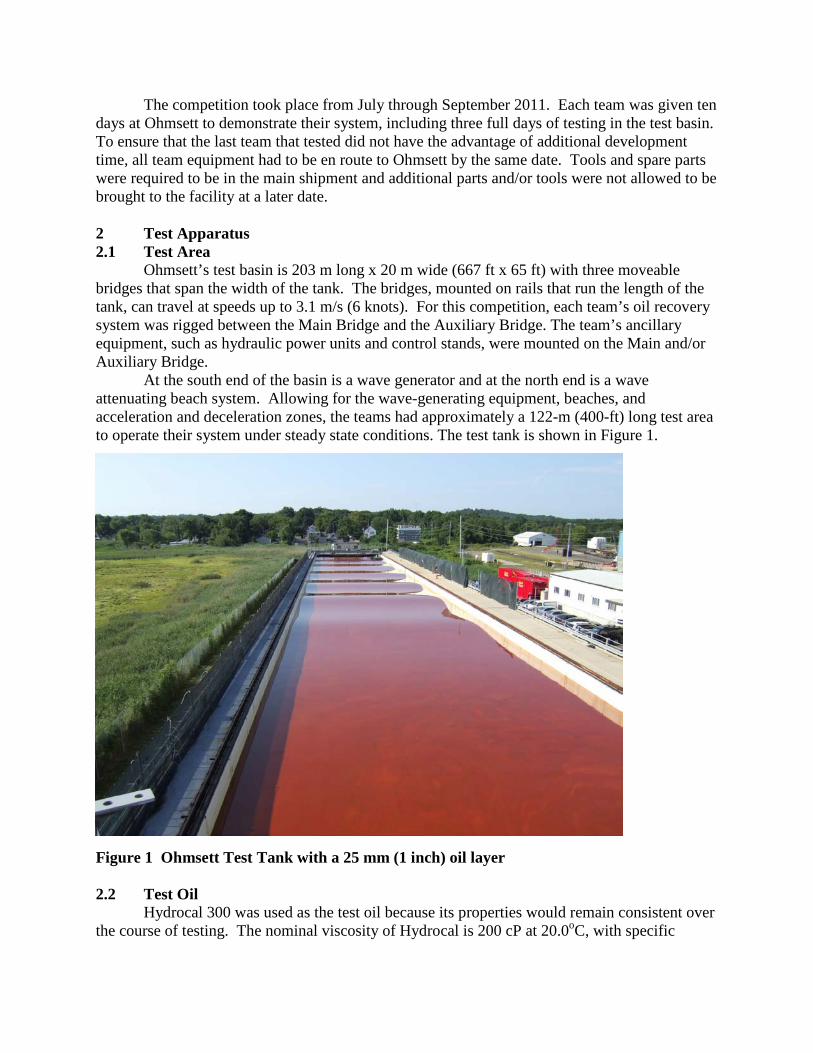
At the south end of the basin is a wave generator and at the north end is a wave attenuating beach system. Allowing for the wave-generating equipment, beaches, and acceleration and deceleration zones, the teams had approximately a 122-m (400-ft) long test area to operate their system under steady state conditions. The test tank is shown in Figure 1.
Figure 1 Ohmsett Test Tank with a 25 mm (1 inch) oil layer 2.2 Test Oil
Hydrocal 300 was used as the test oil because its properties would remain consistent over the course of testing. The nominal viscosity of Hydrocal is 200 cP at 20.0oC, with specific

gravity of 0.903, and interfacial tension of 20.6 dynes per cm at 25.5oC. The Hydrocal was dyed red for better visibility. 2.3 Slick Thickness
To achieve the nominal slick thickness of 25-mm (1-inch) for the oil recovery systems to encounter the required 102,000 L (27,000 gal), oil was dispensed on the surface of the tank. A VisiScreen device was used to measure and document the slick thicknesses at multiple locations in the test basin prior to each test. 2.4 Oil Distribution and Sampling
76,000 L (20,000 gal) calibrated frac tanks were used to store the 303,000 L (80,000 gal) of test oil. As test oil was transferred from the frac tanks to the test basin, the oil levels in the frac tanks were carefully measured to ensure the proper amount of oil was transferred to create the 25-mm thick (1-inch) slick. As oil was dispensed into the test tank, samples were obtained and analyzed to confirm initial oil properties. Multiple oil surface samples were obtained and analyzed for initial properties prior to each official test. 2.5 Oil Recovery
Two banks of four-cell calibrated recovery tanks, located on Ohmsett’s Auxiliary Bridge, were used during the test (Figure 2). Each of the eight recovery tanks had a capacity of approximately 2,300 L (600 gal) and for sounding purposes, equates to 1.8 L/mm (11.8 gal/in). Fluid depth was measured with a 1.2 m (4 ft) aluminum ruler, and readings were accurate to within 3 mm (1/8 in).
Figure 2 Recovery Tanks on the Auxiliary Bridge
The skimmer’s discharge line was connected to Ohmsett’s manifold system via a 254-mm (10-inch) flange. A wye downstream of the flange split the flow into two 254-mm (10-inch) pipes, and recovered fluid traveled 4.5 m (15 ft) vertically up to a 203-mm (8-inch) 3-way valve located at each recovery tank. Each manually operated 3-way valve either diverted flow to bypass mode or to collect mode. As each skimmer was allowed to reach to steady state conditions, fluid flow was diverted to bypass mode where the fluid traveled through the manifold and returned to the basin surface. Once the timed collection period started, flow was diverted to the recovery tanks. Prior to test end, flow was redirected to bypass and the collection period ended.
The volume of oil recovered was determined in the following manner. At test end, fluid soundings of each recovery tank cell were obtained to determine total volume of fluid recovered. Following a 30-minute period in which gravity separation took place, free water was decanted from the bottom of each recovery tank cell. A second set of fluid soundings were obtained from which the gross oil volume was calculated. The remaining fluid was stirred and a representative sample was obtained and sent to Ohmsett’s on-site lab for water content analysis per ASTM D-1796 (ASTM, 2011). After deducting the free and entrained water from the total fluid recovered, the volume of (pure) oil recovered was determined. Valves located at the bottom of each recovery tank cell allowed for visual decanting of free water.
3 Test Procedure
This was an advancing skimmer test and the methodology was developed based on guidelines from ASTM’s F-2709, Standard Test Method for Determining Nameplate Recovery Rate of Stationary Oil Skimmer Systems (ASTM 2008a) and ASTM F-631, Standard Guide for Collecting Skimmer Performance Data in Controlled Environments (ASTM, 2008b). 3.1 Preliminary Tests
The ASTM F-2709 standard suggests a minimum measurement period of 30 seconds (ASTM, 2008a). The minimum 30 second test period would be waived only if the system filled all eight recovery tanks (18,000 L (4800 gallons)) within 30 seconds. Other applicable data collection, measurement and sampling techniques were integrated into the protocol based on ASTM standards.
Prior to official testing, each manufacturer was allowed one day of practice runs to adjust equipment settings and operational speeds to optimize their system and determine the best tow speeds for calm and wave conditions. 3.2 Performance Tests
The measurement period for each test began when: • The skimmer system was at its proper tow speed; • The skimming system was adjusted to its optimum setting; • The oil recovery and discharge flow appeared to be at steady state; • The team signaled they were ready to begin the measurement period.
When the above conditions were met, the 3-way valve on each bank of recovery tanks was swung to divert the flow from bypass mode to collect mode and timing started.
The test could end in three possible ways: typically the team leader signaled to end the test period; the tanks were full; or the end of the test distance was reached. At test end flow was

redirected to bypass mode and timing ceased. All measurements were taken and the skimmer system was repositioned to start the next test.
3.3 Calculation of Performance Measurements/Oil Recovery Rate and Oil Recovery Efficiency The two performance measurements are:
Oil Recovery Rate (ORR): Total volume of oil recovered per unit time.
Voil ORR = t (1) Where: ORR = Oil Recovery Rate, L/min (gpm) Voil = Volume of oil recovered, L (gal) (decanted and lab corrected)
t = Elapsed time of recovery, minutes
and: Recovery Efficiency (RE): The ratio of the volume of oil recovered to the volume of total fluid recovered.
Voil RE = X 100 Vtotal fluid (2) Where: RE = Recovery Efficiency, % Vtotal fluid = Volume of total fluid (water and oil) recovered 4 The Teams 4.1 Voraxial – Florida, USA The Voraxial® Separator was originally designed in the aftermath of the Valdez Oil Spill in 1989. The concept was a high “g” force and continuous flow machine that separates large volumes of fluids based on their different densities. The low shear Voraxial® impeller was designed to produce a vortex in the fluids flowing through the unit with the heavier fluids (water) being drawn to the outside of the vortex, while the lighter materials (oil) are drawn to form a central core. The manifold at the exit of the separation chamber was used to collect the separated streams. The oil recovery system’s inflatable boom concentrated the oil into the apex where the oil entered the system via a large weir/collector (Figure 3). The fluid passed through a semi-submerged oil/water separator before it was pumped to the recovery tanks on the Auxiliary Bridge.

Figure 3 Voraxial skimmer system 4.2 PPR – Alaska, USA The open water skimming system, a long standing concept of PPR, was built to respond to the Deepwater Horizon disaster. The system was based on materials and technology currently in use in other maritime applications. The PPR system, as shown in Figure 4, used an inflatable boom to concentrate the oil and channel it into its collector. Fluid at the collector was drawn up and through a twin-tank vacuum system, and sent to the recovery tanks on the Auxiliary Bridge.
Figure 4 PPR skimmer system 4.3 OilWhale – Finland
The team developed a concept where fluid properties such as viscosity, temperature, pump ability, or stiffness, would not prevent the system from functioning efficiently nor decrease its performance. The OilWhale system used steel boom arms pin connected to the skimming

vessel to direct fluid over a weir and into a self-decanting collection tank (Figure 5). Two Yamaha personal watercraft (PWC), located in the collection tank, were used to pump recovered fluid up to the recovery tanks via discharge hoses attached to the PWC’s water jet nozzles.
Figure 5 OilWhale skimmer system 4.4 Vor-Tek – California, USA The Vor-Tek system, as shown in Figure 6, was designed to function not only as a containment boom/barrier but also as an integrated extraction line capable of removing contaminants (oil) from water for processing through separation systems. The system used a series of eight interconnected modular weir units that doubled as a collection boom and induction line capable of trapping and siphoning hazardous waste from surface and subsurface water. Fluid passed over the weirs and flowed to a collector at the apex of the system where it was drawn up via a self-priming pump located on the Auxiliary Bridge before flowing to the recovery tanks.
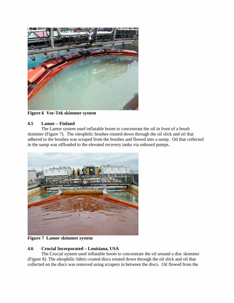
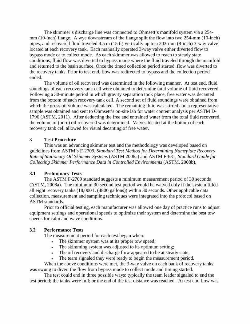
Figure 6 Vor-Tek skimmer system 4.5 Lamor – Finland The Lamor system used inflatable boom to concentrate the oil in front of a brush skimmer (Figure 7). The oleophilic brushes rotated down through the oil slick and oil that adhered to the brushes was scraped from the brushes and flowed into a sump. Oil that collected in the sump was offloaded to the elevated recovery tanks via onboard pumps.
Figure 7 Lamor skimmer system 4.6 Crucial Incorporated – Louisiana, USA
The Crucial system used inflatable boom to concentrate the oil around a disc skimmer (Figure 8). The oleophilic fabric-coated discs rotated down through the oil slick and oil that collected on the discs was removed using scrapers in between the discs. Oil flowed from the

discs, down the scrapers and into a sump, where pumps offloaded the oil up to the calibrated recovery tanks.
Figure 8 Crucial Incorporated skimmer system 4.7 OilShaver – Norway The OilShaver technology was based on a shaving process where the oil spill film is shaved off the surface before it is exposed to the turbulence induced by the collection device. The shaved off oil was directed into a containment channel created by two parallel booms (Figure 9). Surface oil striking the first boom entered the channel via slits in the fabric. Oil self-decanted as it flowed down the channel and entered a collector unit at the end of the channel, where the fluid was pumped to the recovery tanks on the Auxiliary Bridge.
Figure 9 OilShaver skimmer system 4.8 Koseq – Netherlands This system used steel V-shaped boom arms pin connected to the skimmer to direct oil to its collection tank where fluid flowed over weir and into a collection tank (Figure 10). The

weir’s height continuously adjusted based on feedback from a sensor mounted in front of the weir. Recovered fluid that passed over the weir and into the collection tank was pumped up to the recovery tanks on the Auxiliary Bridge.
Figure 10 Koseq skimmer system 4.9 $300,000 Second Place Winner: NOFI – Norway NOFI tested a single vessel unit called the Current Buster 6, which collects, separates and stores oil. Their system was designed with flexible V-shaped surface boom arms that extended forward and outward to channel oil through a narrow throat in the system (Figure 11). The fluid entered a more open, semi-quiescent area which allowed the fluid to self-decant before pumps offloaded the fluid to the recovery tanks on the Auxiliary Bridge.
Figure 11 The NOFI skimmer system

4.10 $1 Million First Place Winner: Elastec/American Marine – Illinois, USA Elastec’s system used four banks of oleophilic discs that were mounted between two pontoons (Figure 12). The oleophilic discs, which had concentric grooves in them, rotated through the oil slick and oil that adhered to the discs was scraped into a sump. Pumps in the sump transferred the recovered fluid to the recovery tanks on the Auxiliary Bridge.
Figure 12 The Elastec/American Marine skimmer system 5 Results
After each team’s system was rigged in the tank, the team was given one day of test runs to optimize their system’s settings and determine their optimum tow speed between 0.5m/s – 2.0m/s (1 and 4 knots). Following the optimization day, teams were given two additional days to complete up to four runs in calm conditions and four runs in wave conditions. Test results were valid if they were within 20% of the calm or wave run mean. The final combined mean was calculated by averaging the three best calm water runs and the three best wave runs (Table 1).
Table 1 Summary of Results
Team ORR combined
RE combined
(%)
ORR calm
RE calm (%)
ORR waves
RE waves (%)
Elastec Fig. 12
17,678 L/min 4670 gpm
89.5 17,814 L/min 4,706 gpm
88.9 17,538 L/min 4,633 gpm
90.1
NOFI Fig. 11
10,266 L/min 2,712 gpm
83.0 11,197 L/min 2,958 gpm
91.9 9,335 L/min 2,466 gpm
74.0

Koseq Fig. 10
7,817 L/min 2,065 gpm
87.9 8,748 L/min 2,311 gpm
98.2 6,882 L/min 1,818 gpm
77.6
OilShaver Fig. 9
7,597 L/min 2,007 gpm
90.7 7,601 L/min 2,008 gpm
92.6 7,594 L/min 2,006 gpm
88.8
Crucial Fig. 8
7,147 L/min 1,888 gpm
71.3 8,135 L/min 2,149 gpm
79.7 6,155 L/min 1,626 gpm
62.8
Lamor Fig. 7
5,349 L/min 1,413 gpm
92.5 5,156 L/min 1,362 gpm
91.4 5,546 L/min 1,465 gpm
93.6
Vor-Tec Fig. 6
8,589 L/min 2,269 gpm
57.3 11,409 L/min 3,014 gpm
72.1 5,773 L/min 1,525 gpm
42.5
OilWhale Fig. 5
3,865 L/min 1,021 gpm
42.8 5,894 L/min 1,557 gpm
44.6 1,836 L/min 485 gpm
41.0
PPR Fig. 4
3,642 L/min 962 gpm
92.1 3,956 L/min 1,045 gpm
96.9 3,324 L/min 878 gpm
87.3
Voraxial Fig. 3
2,623 L/min 693 gpm
49.2 3,562 L/min 941 gpm
63.9 1,685 L/min 445 gpm
34.5
6 Summary
Ten skimming systems were tested at Ohmsett in the $1.4 Million Wendy Schmidt Oil Cleanup X CHALLENGE. Although there were numerous concepts explored, the following are a few of the most notable in which their potential was validated through this competition. Elastec’s innovative advancement was the ability to create a large surface area within what was typically a standardize oleophilic disc skimmer surface.
NOFI’s system development of a channel which reduced relative velocity and allowed for oil/water separation to take place. Ultimately recovered fluid was directed to a system storage tank at which further natural oil/water separation took place prior to selected offloading of the recovered oil.
Koseq’s innovative technology was the dynamic weir which efficiently made a selective cut of surface oil into the skimmer. OilShaver’s very unique attribute of this system was its ability to be towed from one point as a vessel side collection unit. Its design was unique in concept were surface oil was literally shaved by a downward angled plane and directed through a separation channel to a recovery device.
Crucial’s technology was the fibrous coated oleophilic disc in which surface net area was significantly increased due to the fibrous cloth covering.
Prior to the X CHALLENGE, the highest ORR measured at Ohmsett was approximately 3,400 L/min (900 gpm) with a RE over 70%. To qualify for a prize, a system’s ORR had to exceed 9,464L/min (2500 gpm) with at least a 70% RE. Two teams surpassed these goals: the $300,000 second place winner, NOFI, achieved a combined ORR of 10,266 L/min (2712 gpm) with a RE of 83.0%; the $1 Million first place winner, Elastec/American Marine, had a combined ORR of 17,678 L/min (4670 gpm) with a RE of 89.5%. Elastec/American Marine’s ORR was five times greater than the highest capacity skimmer previously tested at Ohmsett.

7 Acknowledgements The authors would like to acknowledge the assistance of the U.S. Department of Interior
Bureau of Safety and Environmental Enforcement (BSEE), X PRIZE Foundation, and the staff of MAR, Inc., who operate Ohmsett under contract with BSEE.
8 References
ASTM, Annual Book of ASTM Standards: F 2709 - Standard Test Method for Determining Nameplate Recovery Rate of Stationary Oil Skimmer Systems, American Society for Testing and Materials, West Conshohocken, PA, 2008a. ASTM, Annual Book of ASTM Standards: F 631 - Standard Guide for Collecting Skimmer Performance Data in Controlled Environments, American Society for Testing and Materials, West Conshohocken, PA, 2008b. ASTM, Annual Book of ASTM Standards: D 1796 – Standard Test Method for Water and Sediment in Fuel Oils by the Centrifuge Method (Laboratory Procedure), American Society for Testing and Materials, West Conshohocken, PA, 2011.