high electrochemical selectivity of edge versus terrace...
TRANSCRIPT

High Electrochemical Selectivity of Edge versus Terrace Sites in Two-Dimensional Layered MoS2 MaterialsHaotian Wang,† Qianfan Zhang,*,‡ Hongbin Yao,§ Zheng Liang,§ Hyun-Wook Lee,§ Po-Chun Hsu,§
Guangyuan Zheng,∥ and Yi Cui*,§,⊥
†Department of Applied Physics, Stanford University, Stanford, California 94305, United States‡School of Materials Science and Engineering, Beihang University, Beijing 100191, People’s Republic of China§Department of Materials Science and Engineering and ∥Department of Chemical Engineering, Stanford University, Stanford,California 94305, United States⊥Stanford Institute for Materials and Energy Sciences, SLAC National Accelerator Laboratory, 2575 Sand Hill Road, Menlo Park,California 94025, United States
*S Supporting Information
ABSTRACT: Exploring the chemical reactivity of differentatomic sites on crystal surface and controlling their exposuresare important for catalysis and renewable energy storage. Here,we use two-dimensional layered molybdenum disulfide(MoS2) to demonstrate the electrochemical selectivity ofedge versus terrace sites for Li−S batteries and hydrogenevolution reaction (HER). Lithium sulfide (Li2S) nanoparticlesdecorates along the edges of the MoS2 nanosheet versusterrace, confirming the strong binding energies between Li2S and the edge sites and guiding the improved electrode design forLi−S batteries. We also provided clear comparison of HER activity between edge and terrace sites of MoS2 beyond the previoustheoretical prediction and experimental proof.
KEYWORDS: Electrochemical selectivity, Two-dimensional materials, MoS2, Li−S batteries, Hydrogen evolution reaction
Understanding the effects of different atomic sites oncrystal surface is critical to control chemical reactions
with great importance, ranging from materials synthesis,catalysis, to energy storage.1−8 Exposed facets, corners, steps,kinks, and edges on the surfaces of crystals have been shown toexhibit different chemical reactivity.9−15 Two-dimensional (2D)layered crystal materials have recently attracted tremendousinterests as electronic, optoelectronic, and catalytic materi-als.16−19 They have strong intralayer covalent bonding andweak interlayer van der Waals force and are expected tomanifest the difference of chemical reactivity between the edgesites with uncoordinated atoms and the fully coordinatedterrace sites.12,13 There exist a few examples on the differentchemical reactivity of terrace and edge sites of 2D materials.The terrace and edge sites of graphite electrodes in lithium ionbatteries exhibit dissimilar electrochemical reactivity during thesolid electrolyte interface formation.20 Electrodeposition ofmaterials takes place preferentially at the line edges of graphite,resulting in the formation of nanowires.13,21 The edge sites ofmolybdenum disulfide (MoS2) show much higher electro-chemical catalytic activity than the terrace counterpart incatalyzing hydrodesulfurization and hydrogen evolution.12,22
Therefore, understanding the properties of the sites andmanipulating the proper site exposure on the surface of 2Dmaterials becomes important in materials synthesis, batteries,and catalysis.
In this work, we exploit well-defined edge-exposed (layervertically aligned nanofilms) and terrace-exposed (horizontalnanosheets and nanocages) MoS2 samples to demonstrate highelectrochemical selectivity of edge versus terrace sites forlithium sulfide (Li2S) electrochemical deposition in high energyLi−S batteries and electrocatalysis of hydrogen evolutionreaction (HER). Recently Li−S batteries have been heavilyinvestigated due to the low cost, high specific capacity of S(1673 mAh/g), and high theoretical specific energy (2600 Wh/kg),23,24 which are attractive for portable electronics andelectrical transportations.25 However, the polysulfide dissolu-tion during battery charge/discharge has been a majorchallenge causing capacity decay.25,26 Many approaches havebeen developed to address this challenge including (1) physicalconfinement of polysulfide with porous nanostructures,polymers, rationally designed hollow nanoparticles and yolk−shell structures,23,27−31 (2) increasing chemical interaction withpolysulfide using polar polymers and inorganics,32,33 (3)changing electrolyte to reduce polysulfide solubility,34 and (4)dispersing S into microporous structures to avoid polysulfideformation.35 In all these studies, appreciable amount (10−15%)of polysulfide dissolution still takes place, causing the capacity
Received: September 29, 2014Revised: November 3, 2014
Letter
pubs.acs.org/NanoLett
© XXXX American Chemical Society A dx.doi.org/10.1021/nl503730c | Nano Lett. XXXX, XXX, XXX−XXX
decay. Therefore, controlling spatially the electrochemicaldeposition of soluble polysulfides is important as shownrecently in selective deposition of S species on conductingoxide surface instead of carbon.33 In addition to Li−S batteries,Li metal polysulfide semiflow batteries as an attractive conceptfor grid-scale energy storage also calls for the controlleddeposition of polysulfides.36
We recently demonstrated that 2D transition metal disulfidesare effective encapsulation materials for improved Li2S cathodesdue to the strong interactions with Li2S;
37 however, the site-dependent binding energies with S species are still unclear.Understanding polysulfide binding with different crystal sites iscritical for controlled polysulfide deposition. We propose that2D layered materials afford well-defined model system tounderstand site-dependent deposition due the drastic differenceof edge and terrace sites and are potentially practical solutions.Results and Discussions. We first demonstrate the
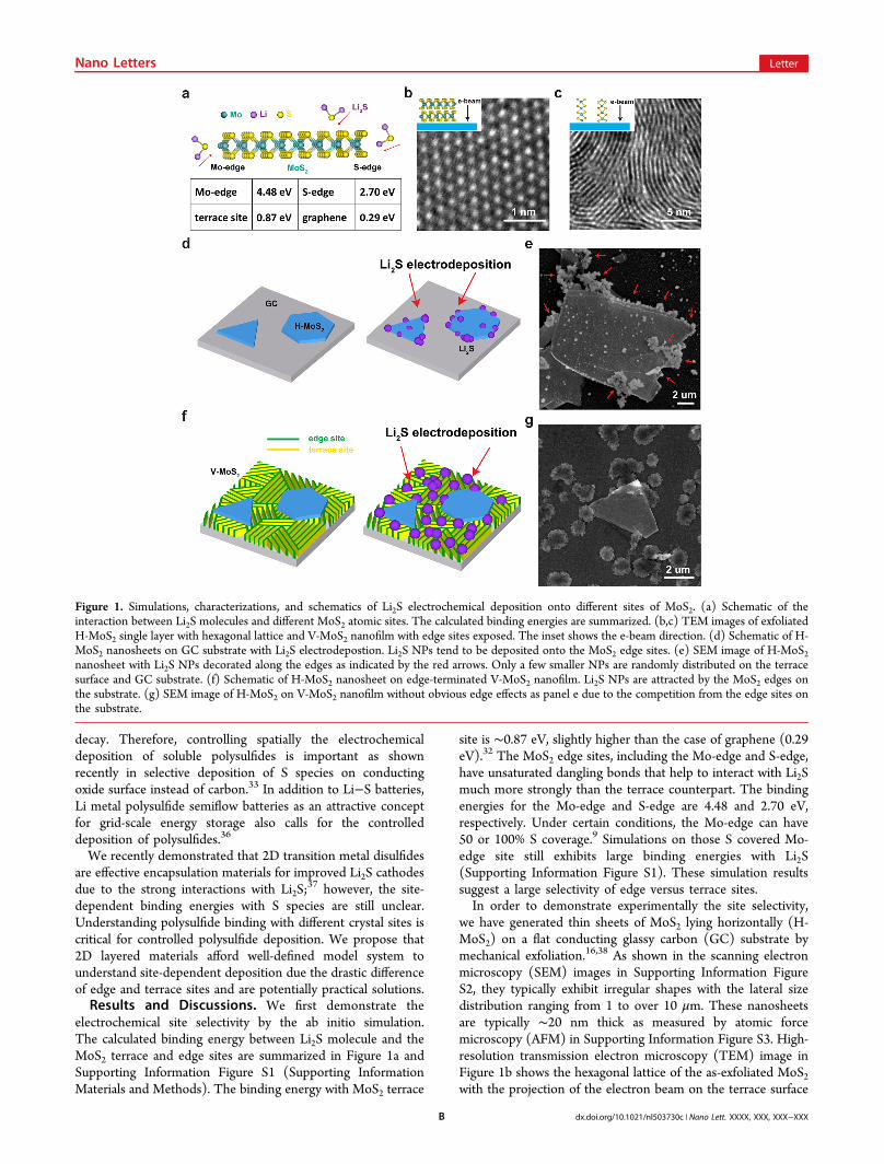
electrochemical site selectivity by the ab initio simulation.The calculated binding energy between Li2S molecule and theMoS2 terrace and edge sites are summarized in Figure 1a andSupporting Information Figure S1 (Supporting InformationMaterials and Methods). The binding energy with MoS2 terrace
site is ∼0.87 eV, slightly higher than the case of graphene (0.29eV).32 The MoS2 edge sites, including the Mo-edge and S-edge,have unsaturated dangling bonds that help to interact with Li2Smuch more strongly than the terrace counterpart. The bindingenergies for the Mo-edge and S-edge are 4.48 and 2.70 eV,respectively. Under certain conditions, the Mo-edge can have50 or 100% S coverage.9 Simulations on those S covered Mo-edge site still exhibits large binding energies with Li2S(Supporting Information Figure S1). These simulation resultssuggest a large selectivity of edge versus terrace sites.In order to demonstrate experimentally the site selectivity,
we have generated thin sheets of MoS2 lying horizontally (H-MoS2) on a flat conducting glassy carbon (GC) substrate bymechanical exfoliation.16,38 As shown in the scanning electronmicroscopy (SEM) images in Supporting Information FigureS2, they typically exhibit irregular shapes with the lateral sizedistribution ranging from 1 to over 10 μm. These nanosheetsare typically ∼20 nm thick as measured by atomic forcemicroscopy (AFM) in Supporting Information Figure S3. High-resolution transmission electron microscopy (TEM) image inFigure 1b shows the hexagonal lattice of the as-exfoliated MoS2with the projection of the electron beam on the terrace surface
Figure 1. Simulations, characterizations, and schematics of Li2S electrochemical deposition onto different sites of MoS2. (a) Schematic of theinteraction between Li2S molecules and different MoS2 atomic sites. The calculated binding energies are summarized. (b,c) TEM images of exfoliatedH-MoS2 single layer with hexagonal lattice and V-MoS2 nanofilm with edge sites exposed. The inset shows the e-beam direction. (d) Schematic of H-MoS2 nanosheets on GC substrate with Li2S electrodepostion. Li2S NPs tend to be deposited onto the MoS2 edge sites. (e) SEM image of H-MoS2nanosheet with Li2S NPs decorated along the edges as indicated by the red arrows. Only a few smaller NPs are randomly distributed on the terracesurface and GC substrate. (f) Schematic of H-MoS2 nanosheet on edge-terminated V-MoS2 nanofilm. Li2S NPs are attracted by the MoS2 edges onthe substrate. (g) SEM image of H-MoS2 on V-MoS2 nanofilm without obvious edge effects as panel e due to the competition from the edge sites onthe substrate.
Nano Letters Letter
dx.doi.org/10.1021/nl503730c | Nano Lett. XXXX, XXX, XXX−XXXB

of the layer. A pouch battery cell, with the H-MoS2 on GC ascathode, Li metal as anode, and 10 ul of 0.5 M Li2S8 polysulfidesolution (based on S) as catholyte, was used to perform theelectrochemical deposition with current density of 2.5 μA/cm2
(Supporting Information Materials and Methods). As illus-trated in the schematic of Figure 1d, we expect that Li2S wouldtend to be deposited at edge sites due to the high bindingenergies of Li2S species there. The SEM image in Figure 1eshows that the deposited Li2S NPs are mostly distributed at theedges of the nanosheet highlighted by the arrows. On top of thenanosheet there are visible steps with additional exposed edgesites, which also bind a large number of Li2S particles.Compared with the MoS2 edge sites, there are only a fewLi2S NPs with much smaller sizes distributed on the terracesurface of the nanosheet and the GC substrate. We note thatthe NPs are still decorated along the edges during charging thebattery for S deposition as shown in Supporting InformationFigure S4a, suggesting the same electrochemical selectivity ofthe edges for S deposition.33 However, this selectivity would belost if we use mild oxidation to pretreat MoS2 (SupportingInformation Figure S4b, Materials and Methods), which wouldchange the surface functional groups on both edge and a part ofterrace sites to O or OH groups.39 No obvious edge effectsobserved in Supporting Information Figure S4b again confirmsthat the high electrochemical selectivity results from theinteraction of Li2S and the fresh edge sites and, moreimportantly, rules out any possible physical geometricinfluences on the Li2S deposition.To further show the edge selectivity, we use an edge-
terminated surface to study the electrodeposition. Recently, wedeveloped a method of the rapid sulfurization reaction toconvert Mo thin film (5 nm) into layer vertically aligned MoS2(V-MoS2) thin film (20 nm) on the GC substrate (SupportingInformation Materials and Methods).40 As shown in the TEMimage in Figure 1c the MoS2 layers are parallel to the electronbeam, or perpendicular to the substrate, with nearly 100% edge
sites exposed on the surface. We used mechanical exfoliation totransfer some MoS2 nanosheets onto the V-MoS2 thin film andcreated a sample with mostly edge sites and a few terrace sites.We expect that the distribution of Li2S NPs after electro-deposition will change significantly when the MoS2 edge-terminated surface substitutes for the carbon surface asillustrated in Figure 1f. The ability of the H-MoS2 edges toattract S species for deposition is reduced to a considerableextent due to the rising competition from the V-MoS2 edgesites. Li2S NPs tend to be randomly distributed on the wholesurface area except for the terrace surface of the H-MoS2. InFigure 1g, there are Li2S particles sitting along the edges of thenanosheet; however, even more particles are distributed aroundthe nanosheet, showing no distinct H-MoS2 edge effects. NoLi2S NPs are observed on the terrace surface of the H-MoS2except for the corners. Notice that the sizes and morphologiesof the Li2S NPs are different from those in Figure 1e, possiblydue to the varied surface chemistry, which definitely influencesthe nucleation process.41 A comparison of the selectivitybetween MoS2 edge sites and carbon is by the distribution ofelectrodeposited Li2S NPs on these two patterned surfaces(Supporting Information Figure S5). The Li2S NPs areconcentrated on the MoS2 edge-terminated instead of theGC surface, again confirming the strong electrochemicalselectivity of MoS2 edge sites.With all the above simulation and experimental results, we
can conclude that MoS2 edge sites have much higherelectrochemical selectivity and activity than its terrace surface,which provides important guidance to the battery electrodematerials design. Here we use this design principle ofmaximizing edge site exposure to synthesize three-dimensionalelectrodes for studying the Li−S battery cell performance. Afree-standing, high surface area and low weight-conductingcarbon nanofiber (CNF) matrix (Supporting InformationFigure S6) is obtained by electrospinning the nanofibers ofpolyacrylonitrile (PAN) and polypyrrolidone (PVP) followed
Figure 2. TEM images and Raman spectra of MoS2 with different atomic sites exposed on CNF. (a) TEM image of a typical CNF. The diameterranges from 100 to 200 nm. (b,c) TEM images of V-MoS2 on CNF with edge sites exposed. The CNF surface is uniformly covered with MoS2 edges.The inset shows the schematic of the MoS2 structure on the CNF. (d,e) TEM images of C-MoS2 NPs on CNF with only terrace sites exposed. MoS2tends to hide the exposed edge sites by forming buckyball like structure layer by layer. (f) Raman spectra of different MoS2 structures. The integratedintensity ratio of E2g
1 to A1g offers rich information about the orientation of the MoS2 molecular layers.
Nano Letters Letter
dx.doi.org/10.1021/nl503730c | Nano Lett. XXXX, XXX, XXX−XXXC
by a simple carbonization process (Supporting InformationMaterials and Methods).42 The TEM image in Figure 2a showsa typical CNF with the diameter of 100 to 200 nm. To coat thecarbon surface with MoS2 edges, we employed the simple dip-coating of ammonium molybdate solution method for MoO3
NPs synthesis, followed by the rapid sulfurization process under600 °C to become MoS2 (Supporting Information Materialsand Methods).43 The TEM images in Figure 2b,c as well as theinset schematic clearly reveal that the MoS2 layers are verticallystanding on the CNF with edges exposed. The blurred areaswithout observable edges in the images may be due to the tiltedlayers on the curved surface of the CNF.44 The edge andterrace site exposure can be easily manipulated by adjusting thesulfurization temperature and time. For example, we can alsoreduce the edge site exposure to minimum by forming cage-likeMoS2 nanoparticles (C-MoS2) with self-closed layers, alsoknown as inorganic fullerene-like MoS2 NPs (Figure 2d,e),
45,46
simply by increasing the reaction temperature to 800 °C andthe growth time to 5 h. The C-MoS2 exposes terrace sitesinstead of the edge sites. The C-MoS2 is considered to bethermodynamically more stable than the V-MoS2,
40 whichexplains why the C-MoS2 dominates under the high-temper-ature, long growth time condition.46 The comparison of Ramanspectra among the three different MoS2 structures (H-MoS2, V-MoS2, C-MoS2) in Figure 2f is very intriguing and offers richinformation. The H-MoS2 nanosheet exhibits E2g
1 and A1g
vibration modes with similar integrated intensities (E2g1/A1g ≈
1:1.4), consistent with previous studies.47 V-MoS2 has acompletely different intensity ratio of E2g
1 to A1g (≈ 1:3)where the A1g mode with the out of plane vibration direction isfavored by the layer vertically standing structure.40,48 Theintensity ratio of C-MoS2 (≈ 1:2) positions well within the
range of the two limiting conditions due to the curvedmolecular layers.40
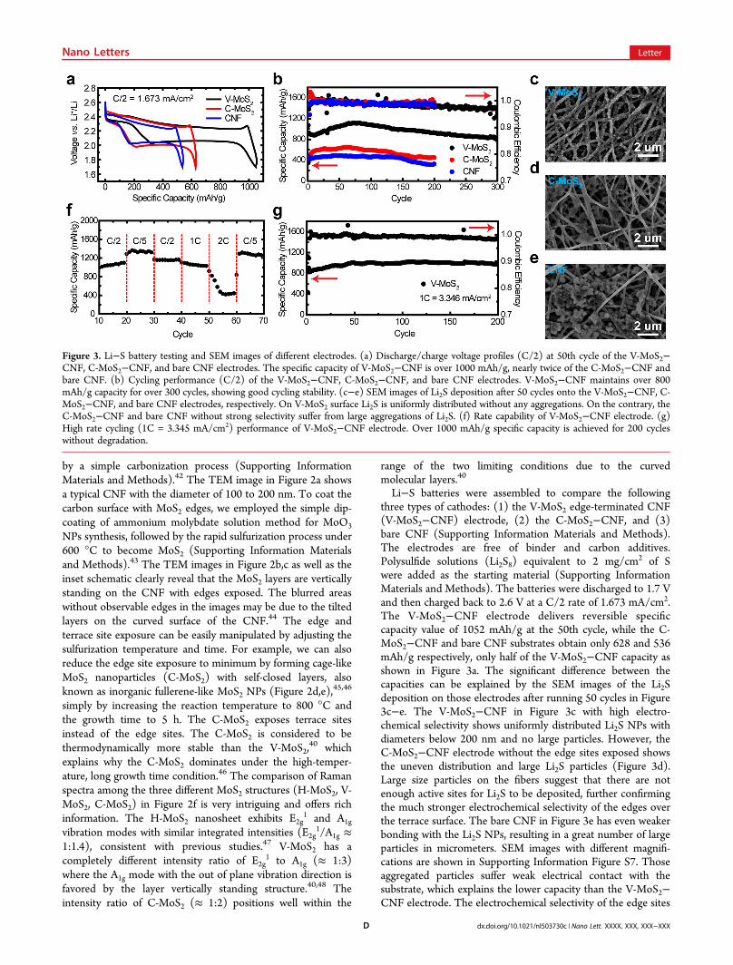
Li−S batteries were assembled to compare the followingthree types of cathodes: (1) the V-MoS2 edge-terminated CNF(V-MoS2−CNF) electrode, (2) the C-MoS2−CNF, and (3)bare CNF (Supporting Information Materials and Methods).The electrodes are free of binder and carbon additives.Polysulfide solutions (Li2S8) equivalent to 2 mg/cm2 of Swere added as the starting material (Supporting InformationMaterials and Methods). The batteries were discharged to 1.7 Vand then charged back to 2.6 V at a C/2 rate of 1.673 mA/cm2.The V-MoS2−CNF electrode delivers reversible specificcapacity value of 1052 mAh/g at the 50th cycle, while the C-MoS2−CNF and bare CNF substrates obtain only 628 and 536mAh/g respectively, only half of the V-MoS2−CNF capacity asshown in Figure 3a. The significant difference between thecapacities can be explained by the SEM images of the Li2Sdeposition on those electrodes after running 50 cycles in Figure3c−e. The V-MoS2−CNF in Figure 3c with high electro-chemical selectivity shows uniformly distributed Li2S NPs withdiameters below 200 nm and no large particles. However, theC-MoS2−CNF electrode without the edge sites exposed showsthe uneven distribution and large Li2S particles (Figure 3d).Large size particles on the fibers suggest that there are notenough active sites for Li2S to be deposited, further confirmingthe much stronger electrochemical selectivity of the edges overthe terrace surface. The bare CNF in Figure 3e has even weakerbonding with the Li2S NPs, resulting in a great number of largeparticles in micrometers. SEM images with different magnifi-cations are shown in Supporting Information Figure S7. Thoseaggregated particles suffer weak electrical contact with thesubstrate, which explains the lower capacity than the V-MoS2−CNF electrode. The electrochemical selectivity of the edge sites
Figure 3. Li−S battery testing and SEM images of different electrodes. (a) Discharge/charge voltage profiles (C/2) at 50th cycle of the V-MoS2−CNF, C-MoS2−CNF, and bare CNF electrodes. The specific capacity of V-MoS2−CNF is over 1000 mAh/g, nearly twice of the C-MoS2−CNF andbare CNF. (b) Cycling performance (C/2) of the V-MoS2−CNF, C-MoS2−CNF, and bare CNF electrodes. V-MoS2−CNF maintains over 800mAh/g capacity for over 300 cycles, showing good cycling stability. (c−e) SEM images of Li2S deposition after 50 cycles onto the V-MoS2−CNF, C-MoS2−CNF, and bare CNF electrodes, respectively. On V-MoS2 surface Li2S is uniformly distributed without any aggregations. On the contrary, theC-MoS2−CNF and bare CNF without strong selectivity suffer from large aggregations of Li2S. (f) Rate capability of V-MoS2−CNF electrode. (g)High rate cycling (1C = 3.345 mA/cm2) performance of V-MoS2−CNF electrode. Over 1000 mAh/g specific capacity is achieved for 200 cycleswithout degradation.
Nano Letters Letter
dx.doi.org/10.1021/nl503730c | Nano Lett. XXXX, XXX, XXX−XXXD
plays an important role in controlling the Li2S spatialdistribution and as a result improving the performance of thebattery.Cycling stability of the V-MoS2−CNF electrode was tested at
C/2 for over 300 cycles in Figure 3b. The first dischargecapacity is 1068 mAh/g with some decay until the 10th cyclefollowed by a slow activation process to reach 1110 mAh/g atthe 65th cycle. The initial decay is likely due to the reaction ofpolysulfides with Li metal. At the 300th cycle over 800 mAh/g(∼75% of the first cycle), specific capacity is retained with anaverage capacity decay of only 0.08% per cycle. Over the cycles,the discharge capacity of V-MoS2 is nearly twice of the C-MoS2−CNF and bare CNF. Good rate capability of the V-MoS2−CNF electrode is illustrated in Figure 3f with reversiblespecific capacities of 1339, 1152, and 1066 mAh/g at C/5, C/2,and 1C respectively. The capacity drops dramatically at 2C rate,which we assume is due to the diffusion limit of polysulfidespecies in the electrolyte.49 We tested our V-MoS2−CNF Li−Sbattery at 1C rate with impressive charge/discharge currentdensity of 3.346 mA/cm2 for 200 cycles, achieving over 1000mAh/g without any capacity decrease. The outstandingperformance of the high rate testing benefits from the facileelectrochemical deposition of S species on the V-MoS2 edge-terminated surface.The electrochemical selectivity of 2D material edge sites also
plays a critical role in electrocatalysis.12,22 For example, underthe hydrogen evolution condition, the specific atomic structureof MoS2 edge sites provides a proper bonding (not too strongand not too weak) with H, which facilitates both the dischargestep and the H2 releasing process.
12 In the past, measurements
on horizonatal nanoplates of MoS2 were conducted to showthat HER activity is linearly scaled with edge lengths,22 as anevidence of active edge sites. Recent simulation results alsoshow a large free energy of H bonding on terrace sitescompared with the edge sites, confirming that the terrace sitesare not active for HER.50 However, there have not been anystudies to compare the edge-only and terrace-only samplesexperimentally. Here our V-MoS2−CNF and C-MoS2−CNFelectrodes afford such a possibility. The V-MoS2−CNF matrixwas first broken down into small pieces by ball milling, andthen uniformly drop casted onto carbon fiber paper substratewith binders and carbon additives for efficient electrontransport and bubble releasing (Supporting InformationMaterials and Methods). The mass loading of MoS2 is ∼0.25mg/cm2. A standard three-electrode setup was used forperforming electrochemical characterizations in 0.5 M H2SO4
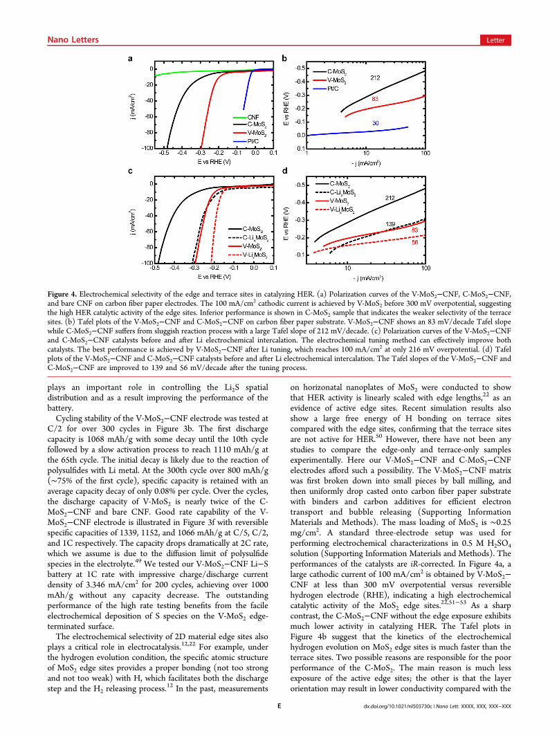
solution (Supporting Information Materials and Methods). Theperformances of the catalysts are iR-corrected. In Figure 4a, alarge cathodic current of 100 mA/cm2 is obtained by V-MoS2−CNF at less than 300 mV overpotential versus reversiblehydrogen electrode (RHE), indicating a high electrochemicalcatalytic activity of the MoS2 edge sites.22,51−53 As a sharpcontrast, the C-MoS2−CNF without the edge exposure exhibitsmuch lower activity in catalyzing HER. The Tafel plots inFigure 4b suggest that the kinetics of the electrochemicalhydrogen evolution on MoS2 edge sites is much faster than theterrace sites. Two possible reasons are responsible for the poorperformance of the C-MoS2. The main reason is much lessexposure of the active edge sites; the other is that the layerorientation may result in lower conductivity compared with the
Figure 4. Electrochemical selectivity of the edge and terrace sites in catalyzing HER. (a) Polarization curves of the V-MoS2−CNF, C-MoS2−CNF,and bare CNF on carbon fiber paper electrodes. The 100 mA/cm2 cathodic current is achieved by V-MoS2 before 300 mV overpotential, suggestingthe high HER catalytic activity of the edge sites. Inferior performance is shown in C-MoS2 sample that indicates the weaker selectivity of the terracesites. (b) Tafel plots of the V-MoS2−CNF and C-MoS2−CNF on carbon fiber paper substrate. V-MoS2−CNF shows an 83 mV/decade Tafel slopewhile C-MoS2−CNF suffers from sluggish reaction process with a large Tafel slope of 212 mV/decade. (c) Polarization curves of the V-MoS2−CNFand C-MoS2−CNF catalysts before and after Li electrochemical intercalation. The electrochemical tuning method can effectively improve bothcatalysts. The best performance is achieved by V-MoS2−CNF after Li tuning, which reaches 100 mA/cm2 at only 216 mV overpotential. (d) Tafelplots of the V-MoS2−CNF and C-MoS2−CNF catalysts before and after Li electrochemical intercalation. The Tafel slopes of the V-MoS2−CNF andC-MoS2−CNF are improved to 139 and 56 mV/decade after the tuning process.
Nano Letters Letter
dx.doi.org/10.1021/nl503730c | Nano Lett. XXXX, XXX, XXX−XXXE
layer vertically aligned structure.40 We also tested theelectrochemical double layer capacity of C-MoS2−CNF andV-MoS2−CNF as a direct comparison of their active surfaceareas. The capacity of V-MoS2−CNF is 16.0 mF, significantlyhigher than that of C-MoS2−CNF (1.3 mF). This largedifference in capacity confirms that the HER active surface areaof V-MoS2−CNF is larger than C-MoS2−CNF (SupportingInformation Figure S8). The stability of the V-MoS2−CNFcatalyst was tested by applying a constant voltage to achieve∼10 mA/cm2 cathodic current for over 2 h (SupportingInformation Figure S9). The negligible decay of the currentsuggests that catalyst is stable under the evolution condition.43
In addition, the morphology of C-MoS2 after constant HERcurrent operation is slightly changed with the cage partiallyopened as indicated in Supporting Information Figure S10. TheHER performance of V-MoS2−CNF could be further optimizedby the Li electrochemical tuning method developed in ourprevious studies (Supporting Information Materials andMethods).43,48 Here both V-MoS2−CNF and C-MoS2−CNFare improved by much as shown in Figure 4c,d. Theintercalated Li helps to dramatically change the electronicstructure of MoS2 from 2H to 1T, creating new HER activesites, and at the same time expanding or exfoliating the layersfor larger surface areas.43,48,54,55 In Supporting InformationFigure S11a, it is difficult to tell whether the layers of V-MoS2on CNF are expanded or not after Li intercalation due to thehighly curved surface of the fibers (on a flat substrate the layerspacing is expanded by ∼10%);48 however, the C-MoS2 isbroken into a noncontinuous shape to open up some edge sitesas shown in Supporting Information Figure S11b. Theselectivity in catalyzing HER further reveals the importanceof the 2D material edge sites in catalysis as well as otherimportant applications.Conclusion. This work illustrates the great importance of
understanding the site-dependent chemical reactivity of 2Dmaterials. The demonstration of electrochemical selectivity ofedge versus terrace sites provides a clear guidance of 2D MoS2design for improved batteries and catalysis, which also opens upopportunities to design and engineer the big family of 2Dmaterials for extended applications.
■ ASSOCIATED CONTENT
*S Supporting InformationMaterials and Methods, Figures S1 to S11 are included. Thismaterial is available free of charge via the Internet at http://pubs.acs.org.
■ AUTHOR INFORMATION
Corresponding Authors*E-mail: [email protected] (Y.C.).*E-mail: [email protected] (Q.Z.).
Author ContributionsH.W. and Y.C. conceived the experiments. H.W., H.Y., and Z.L.synthesized and prepared the materials. H.W., H−W.L., P−C.H., and G.Z. performed characterizations. H.W., H.Y., andZ.L. carried out electrochemical measurements and analyses.Q.Z performed ab initio simulations. All authors contributed toscientific planning and discussions.
NotesThe authors declare no competing financial interest.
■ ACKNOWLEDGMENTS
We acknowledge support by the Department of Energy, Officeof Basic Energy Sciences, Materials Sciences and EngineeringDivision, under contract DE-AC02-76-SFO0515.
■ REFERENCES(1) Stamenkovic, V. R.; Fowler, B.; Mun, B. S.; Wang, G.; Ross, P.N.; Lucas, C. A.; Markovic, N. M. Science 2007, 315 (5811), 493−497.(2) Hansen, T. W.; Wagner, J. B.; Hansen, P. L.; Dahl, S.; Topsøe,H.; Jacobsen, C. J. H. Science 2001, 294 (5546), 1508−1510.(3) Hansen, P. L.; Wagner, J. B.; Helveg, S.; Rostrup-Nielsen, J. R.;Clausen, B. S.; Topsøe, H. Science 2002, 295 (5562), 2053−2055.(4) Over, H.; Kim, Y. D.; Seitsonen, A. P.; Wendt, S.; Lundgren, E.;Schmid, M.; Varga, P.; Morgante, A.; Ertl, G. Science 2000, 287 (5457),1474−1476.(5) Sun, Y.; Xia, Y. Science 2002, 298 (5601), 2176−2179.(6) Peng, X.; Manna, L.; Yang, W.; Wickham, J.; Scher, E.;Kadavanich, A.; Alivisatos, A. P. Nature 2000, 404 (6773), 59−61.(7) Lim, B.; Jiang, M.; Camargo, P. H. C.; Cho, E. C.; Tao, J.; Lu, X.;Zhu, Y.; Xia, Y. Science 2009, 324 (5932), 1302−1305.(8) Chen, C.; Kang, Y.; Huo, Z.; Zhu, Z.; Huang, W.; Xin, H. L.;Snyder, J. D.; Li, D.; Herron, J. A.; Mavrikakis, M.; Chi, M.; More, K.L.; Li, Y.; Markovic, N. M.; Somorjai, G. A.; Yang, P.; Stamenkovic, V.R. Science 2014, 343 (6177), 1339−1343.(9) Lauritsen, J. V.; Kibsgaard, J.; Helveg, S.; Topsoe, H.; Clausen, B.S.; Laegsgaard, E.; Besenbacher, F. Nat. Nanotechnol. 2007, 2 (1), 53−58.(10) Manna, L.; Milliron, D. J.; Meisel, A.; Scher, E. C.; Alivisatos, A.P. Nat. Mater. 2003, 2 (6), 382−385.(11) Lantz, M. A.; Hug, H. J.; Hoffmann, R.; van Schendel, P. J. A.;Kappenberger, P.; Martin, S.; Baratoff, A.; Guntherodt, H.-J. Science2001, 291 (5513), 2580−2583.(12) Hinnemann, B.; Moses, P. G.; Bonde, J.; Jørgensen, K. P.;Nielsen, J. H.; Horch, S.; Chorkendorff, I.; Nørskov, J. K. J. Am. Chem.Soc. 2005, 127 (15), 5308−5309.(13) Zach, M. P.; Ng, K. H.; Penner, R. M. Science 2000, 290 (5499),2120−2123.(14) Tian, N.; Zhou, Z.-Y.; Sun, S.-G.; Ding, Y.; Wang, Z. L. Science2007, 316 (5825), 732−735.(15) Zambelli, T.; Wintterlin, J.; Trost, J.; Ertl, G. Science 1996, 273(5282), 1688−1690.(16) Novoselov, K. S.; Geim, A. K.; Morozov, S. V.; Jiang, D.; Zhang,Y.; Dubonos, S. V.; Grigorieva, I. V.; Firsov, A. A. Science 2004, 306(5696), 666−669.(17) Geim, A. K.; Novoselov, K. S. Nat. Mater. 2007, 6 (3), 183−191.(18) Butler, S. Z.; Hollen, S. M.; Cao, L.; Cui, Y.; Gupta, J. A.;Gutierrez, H. R.; Heinz, T. F.; Hong, S. S.; Huang, J.; Ismach, A. F.;Johnston-Halperin, E.; Kuno, M.; Plashnitsa, V. V.; Robinson, R. D.;Ruoff, R. S.; Salahuddin, S.; Shan, J.; Shi, L.; Spencer, M. G.; Terrones,M.; Windl, W.; Goldberger, J. E. ACS Nano 2013, 7 (4), 2898−2926.(19) Chhowalla, M.; Shin, H. S.; Eda, G.; Li, L.-J.; Loh, K. P.; Zhang,H. Nat. Chem. 2013, 5 (4), 263−275.(20) Zhang, S.; Ding, M. S.; Xu, K.; Allen, J.; Jow, T. R. Electrochem.Solid-State Lett. 2001, 4 (12), A206−A208.(21) Walter, E. C.; Zach, M. P.; Favier, F.; Murray, B. J.; Inazu, K.;Hemminger, J. C.; Penner, R. M. ChemPhysChem 2003, 4 (2), 131−138.(22) Jaramillo, T. F.; Jørgensen, K. P.; Bonde, J.; Nielsen, J. H.;Horch, S.; Chorkendorff, I. Science 2007, 317 (5834), 100−102.(23) Ji, X.; Lee, K. T.; Nazar, L. F. Nat. Mater. 2009, 8 (6), 500−506.(24) Bruce, P. G.; Freunberger, S. A.; Hardwick, L. J.; Tarascon, J.-M.Nat. Mater. 2012, 11 (1), 19−29.(25) Yang, Y.; Zheng, G.; Cui, Y. Chem. Soc. Rev. 2013, 42 (7),3018−3032.(26) Ji, X.; Nazar, L. F. J. Mater. Chem. 2010, 20 (44), 9821−9826.(27) Zheng, G.; Yang, Y.; Cha, J. J.; Hong, S. S.; Cui, Y. Nano Lett.2011, 11 (10), 4462−4467.
Nano Letters Letter
dx.doi.org/10.1021/nl503730c | Nano Lett. XXXX, XXX, XXX−XXXF
(28) Jayaprakash, N.; Shen, J.; Moganty, S. S.; Corona, A.; Archer, L.A. Angew. Chem. 2011, 123 (26), 6026−6030.(29) Xiao, L.; Cao, Y.; Xiao, J.; Schwenzer, B.; Engelhard, M. H.;Saraf, L. V.; Nie, Z.; Exarhos, G. J.; Liu, J. Adv. Mater. 2012, 24 (9),1176−1181.(30) Seh, Z. W.; Li, W.; Cha, J. J.; Zheng, G.; Yang, Y.; McDowell, M.T.; Hsu, P.-C.; Cui, Y. Nat. Commun. 2013, 4, 1331.(31) Moon, S.; Jung, Y. H.; Jung, W. K.; Jung, D. S.; Choi, J. W.; Kim,D. K. Adv. Mater. 2013, 25 (45), 6547−6553.(32) Zheng, G.; Zhang, Q.; Cha, J. J.; Yang, Y.; Li, W.; Seh, Z. W.;Cui, Y. Nano Lett. 2013, 13 (3), 1265−1270.(33) Yao, H.; Zheng, G.; Hsu, P.-C.; Kong, D.; Cha, J. J.; Li, W.; Seh,Z. W.; McDowell, M. T.; Yan, K.; Liang, Z.; Narasimhan, V. K.; Cui, Y.Nat. Commun. 2014, 5, 5280.(34) Suo, L.; Hu, Y.-S.; Li, H.; Armand, M.; Chen, L. Nat. Commun.2013, 4, 1481.(35) Xin, S.; Gu, L.; Zhao, N.-H.; Yin, Y.-X.; Zhou, L.-J.; Guo, Y.-G.;Wan, L.-J. J. Am. Chem. Soc. 2012, 134 (45), 18510−18513.(36) Yang, Y.; Zheng, G.; Cui, Y. Energy Environ. Sci. 2013, 6 (5),1552−1558.(37) Seh, Z. W.; Yu, J. H.; Li, W.; Hsu, P.-C.; Wang, H.; Sun, Y.; Yao,H.; Zhang, Q.; Cui, Y. Nat. Commun. 2014, 5, 5017.(38) Radisavljevic, B.; Radenovic, A.; Brivio, J.; Giacometti, V.; Kis, A.Nat. Nanotechnol. 2011, 6 (3), 147−150.(39) Voiry, D.; Salehi, M.; Silva, R.; Fujita, T.; Chen, M.; Asefa, T.;Shenoy, V. B.; Eda, G.; Chhowalla, M. Nano Lett. 2013, 13 (12),6222−6227.(40) Kong, D.; Wang, H.; Cha, J. J.; Pasta, M.; Koski, K. J.; Yao, J.;Cui, Y. Nano Lett. 2013, 13 (3), 1341−1347.(41) Tian, M.; Wang, J.; Kurtz, J.; Mallouk, T. E.; Chan, M. H. W.Nano Lett. 2003, 3 (7), 919−923.(42) Li, D.; Xia, Y. Adv. Mater. 2004, 16 (14), 1151−1170.(43) Wang, H.; Lu, Z.; Kong, D.; Sun, J.; Hymel, T. M.; Cui, Y. ACSNano 2014, 8 (5), 4940−4947.(44) Wang, H.; Kong, D.; Johanes, P.; Cha, J. J.; Zheng, G.; Yan, K.;Liu, N.; Cui, Y. Nano Lett. 2013, 13 (7), 3426−3433.(45) Tenne, R.; Margulis, L.; Genut, M.; Hodes, G. Nature 1992, 360(6403), 444−446.(46) Feldman, Y.; Wasserman, E.; Srolovitz, D. J.; Tenne, R. Science1995, 267 (5195), 222−225.(47) Lee, C.; Yan, H.; Brus, L. E.; Heinz, T. F.; Hone, J.; Ryu, S. ACSNano 2010, 4 (5), 2695−2700.(48) Wang, H.; Lu, Z.; Xu, S.; Kong, D.; Cha, J. J.; Zheng, G.; Hsu,P.-C.; Yan, K.; Bradshaw, D.; Prinz, F. B.; Cui, Y. Proc. Natl. Acad. Sci.U.S.A. 2013, 110 (49), 19701−19706.(49) Shin, E. S.; Kim, K.; Oh, S. H.; Cho, W. I. Chem. Commun. 2013,49 (20), 2004−2006.(50) Tsai, C.; Chan, K.; Abild-Pedersen, F.; Norskov, J. K. Phys.Chem. Chem. Phys. 2014, 16 (26), 13156−13164.(51) Kibsgaard, J.; Chen, Z.; Reinecke, B. N.; Jaramillo, T. F. Nat.Mater. 2012, 11 (11), 963−969.(52) Chen, Z.; Cummins, D.; Reinecke, B. N.; Clark, E.; Sunkara, M.K.; Jaramillo, T. F. Nano Lett. 2011, 11 (10), 4168−4175.(53) Li, Y.; Wang, H.; Xie, L.; Liang, Y.; Hong, G.; Dai, H. J. Am.Chem. Soc. 2011, 133 (19), 7296−7299.(54) Lukowski, M. A.; Daniel, A. S.; Meng, F.; Forticaux, A.; Li, L.;Jin, S. J. Am. Chem. Soc. 2013, 135 (28), 10274−10277.(55) Voiry, D.; Yamaguchi, H.; Li, J.; Silva, R.; Alves, D. C. B.; Fujita,T.; Chen, M.; Asefa, T.; Shenoy, V. B.; Eda, G.; Chhowalla, M. Nat.Mater. 2013, 12 (9), 850−855.
Nano Letters Letter
dx.doi.org/10.1021/nl503730c | Nano Lett. XXXX, XXX, XXX−XXXG