high feed finish milling cutter for aluminium alloys …...a special alloy steel and aluminium body...
TRANSCRIPT

FMAXTOOL NEWS
Feed Maximum (FMAX)milling cutter for ultra efficient and accurate finishing.
* By CG image
High Feed Finish Milling Cutter for Aluminium Alloys
SeriesExpansion
B216G2019.6 Update

1
FMAX
*1
Ultra High Efficiency MachiningThe ultra fine pitch design is ideal for high efficiency machining (vf ≥ 20000 mm/min).
The body protector on the rake face forms chip shapes ideal for disposal and disperses them away from the body. Internal coolant also aids this process. The body is compatible with all centre through coolant arbors.
Light Weight, High Rigidity BodyA special alloy steel and aluminium body combine to provide rigidity and light weight.
High Feed Finish Milling Cutter for Aluminium Alloys
Designed for High SpeedsAnti fly dovetail clamping mechanism.
Body Protector Internal Coolant
Internal coolant and a special chip breaker wall (body protector) provides ideal chip discharge performance.
Dovetail Clamp
Angled Face
Aluminium Alloy
Special Alloy Steel
Standard Through Coolant Arbor
*Graphical Representation.
*1 Except DC=40, 50, 63mm

2
DC=40, 50, 63mm
High Precision, Easy SettingThe combination of both a large and micro screw provides precise run-out adjustment and for adjusting new or re-grinding inserts (5 ɥm or better).
Economy, Multi-useA maximum re-grinding allowance of 0.6 mm is possible on both the peripheral and bottom edges.
Large Adjustment Screw
Micro Adjustment Nut
PCD Grade

3
FMAX100
10 1.06 12 1.8516 1.11 18 1.81
12514 1.44 16 3.3320 1.48 24 3.27
(mm)
NEW
High Efficiency MachiningMulti-blade design ideal for low power machines.
The body protector on the rake face forms chip shapes ideal for disposal and disperses them away from the body. Internal coolant also aids this process. The body is compatible with all centre through coolant arbors.
Body Protector Internal Coolant
Internal coolant and a special chip breaker wall (body protector) provides ideal chip discharge performance.
*Graphical Representation.
DCFor Compact and Smaller Machining Centres FMAX
Number of Teeth WT (kg) Number of Teeth WT (kg)
Light Weight Design of 1.5kg or Less
For Compact and Smaller Machining Centres
Light Weight, High Rigidity BodyA special alloy steel and aluminium body combine to provide rigidity and light weight.
High Feed Finish Milling Cutter for Aluminium Alloys

4
NEW
DC
2.0mm 0.8mm2.0m
m5.0m
m
DC
2.0mm 0.8mm
5.0m
m
DC
2.0mm 0.4mm
5.0m
m
DC
2.0mm 0.8mm
8.0m
m
R0.8
Burr Prevention Type
RE=0.8mm RE=0.4mm
General Purpose Inserts
Burr Prevention Inserts
Long Edge Inserts
Inserts with corner R(RE) = 0.8 mm are excellent for general applications, and can be used in a wide variety of cutting areas.They are able to exhibit outstanding cutting edge stability, particularly under high-load conditions such as heavy interrupted cutting.
The sharpness of inserts with corner R(RE) = 0.4 mm is one of their most notable features. Its effectiveness can be demonstrated by the ability to suppress chatter and maintain finished surfaces.
The tool cutting edge angle is effective at reducing the thickness of chips, with almost no burrs generated in comparison to conventional products.The finely-detailed R shape of the corner portion prevents chipping and enhances both stability and tool life.
Inserts for Specific Applications
RE=0.8mm
The long edge insert is capable of finish cutting of castings with a gate. Therefore, it is possible to reduce the number of cutting passes and to shorten the machining time as well.
Gate<
7mm

5
MD220
MD2030
Diamond Sintered Segment Containing Ultra Microparticle Diamond
Diamond Particles : Give a highly stable cutting edge performance because of the strong bonding.
Bond
Diamond Particles
Binding Material
Bond of Diamond Particles
Fracture Resistance
Wea
r Res
ista
nce
Features of the Grades
Features of MD2030 Features of MD220Intended for milling.Improved fracture resistance when used in unstable applications.The stability of the cutting edge can meet a wide variety of workpiece material and cutting conditions.
Sintered medium grain diamond particles. Wear resistance and fracture resistance are superbly balanced. MD220 can prevent burr formation and achieve long tool life.
Re-grinding of an InsertThe maximum material to be re-grinding is 0.6 mm.Use similar inserts after re-grinding to maintain balance.Problems may occur if the cutter isn't balanced correctly.After re-grinding the minor edge will reduce in size and may affect surface finishes.Check the diameter offset after fitting re-grinding inserts.
* Please contact us regarding optimum re-grinding conditions.
Max 0.6 mm
Max
0.6
mm
Minor Cutting Edge
6
P M K N S H
FMAXP M K N S H
KAPR90°
F
(mm)
(mm)
DCON DC CBDP DAH DCCB LCCB DCSFMS KWW L8 KWL
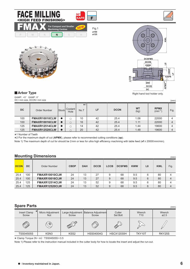
25.4 100 FMAXR10010CLW 24 13 27 9 68 9.5 6 80 425.4 100 FMAXR10016CLW 24 13 27 9 68 9.5 6 80 425.4 125 FMAXR12514CLW 24 13 52 9 68 9.5 6 80 425.4 125 FMAXR12520CLW 24 13 52 9 68 9.5 6 80 4
(mm)
TSS04505S KSN3 KSS2 HSS04004G HSCX12030H TKY10T RKY25S
DC LF DCON WT(kg)
RPMX(min-1)
100 FMAXR10010CLW a 10 42 25.4 1.06 22000 4100 FMAXR10016CLW a 16 42 25.4 1.11 22000 4125 FMAXR12514CLW a 14 42 25.4 1.44 19600 4125 FMAXR12520CLW a 20 42 25.4 1.48 19600 4
y
GAMP: +5° GAMF: 0°
*
LCC
B
DCDCCB
LFCB
DP
APM
X
DCSFMSDCONKWW
KW
LL8
DAH
KAPR
ø100ø125
a : Inventory maintained in Japan.
Fig.1
<HIGH FEED FINISHING>FACE MILLING
Steel Stainless Steel Cast Iron Non-ferrous Metal Difficult-to-Cut Materials Hardened Steel
*1 Number of Teeth
*2 For the maximum depth of cut (APMX), please refer to recommended cutting conditions (ap).Note 1) The maximum depth of cut for should be 2mm or less for ultra high efficiency machining with table feed (vf ≥ 20000mm/min).
Order Number Stock Coolant Hole No.T Fig.
u
u
u
u
Right hand tool holder only.
Order Number Fig.
* Clamp Torque (N • m) : TSS04505S=3.5Note 1) Please refer to the instruction manual included in the cutter body for how to locate the insert and adjust the run-out.
Spare PartsInsert Clamp
ScrewMicro Adjustment
NutLarge Adjustment
ScrewBalance Adjustment
ScrewCutter
Set BoltWrench
T10Wrench
ø2.5
Mounting Dimensions
DC=mm size, DCON=mm size
Arbor Type
For Compact and Smaller Machining Centres
*1
*2

7
P M K N S H
FMAX-40/50/63P M K N S H
DC LF DCON WT(kg)
RPMX(min-1)
40 FMAX-040A04R a 4 40 16 0.24 30000 140 FMAX-040A06R a 6 40 16 0.23 30000 150 FMAX-050A08R a 8 40 22 0.37 30000 150 FMAX-050A10R a 10 40 22 0.35 30000 163 FMAX-063A10R a 10 40 22 0.67 27000 163 FMAX-063A12R a 12 40 22 0.66 27000 1
(mm)
(mm)
DCON DC CBDP DAH DCCB LCCB DCSFMS KWW L8 KWL
16 40 FMAX-040A04R 18 9 14 10 37 8.4 5.6 ─ 116 40 FMAX-040A06R 18 9 14 10 37 8.4 5.6 ─ 122 50 FMAX-050A08R 20 11 17 12 47 10.4 6.3 ─ 122 50 FMAX-050A10R 20 11 17 12 47 10.4 6.3 ─ 122 63 FMAX-063A10R 20 11 17 12 60 10.4 6.3 ─ 122 63 FMAX-063A12R 20 11 17 12 60 10.4 6.3 ─ 1
(mm)
DC
40 FMAX-040 TSS04505S KSN2 KSS2 HSS04004G HSC08030H TKY10T RKY25S50 FMAX-050 TSS04505S KSN2 KSS2 HSS04004G HSC10030H TKY10T RKY25S63 FMAX-063 TSS04505S KSN2 KSS2 HSS04004G HSC10030H TKY10T RKY25S
KAPR90°
F
*
y
GAMP: +5° GAMF: -6°─ -3°
KWL
DCSFMS
DC
DCON
DAHDCCB
KWW
LCCB
L8CBDP
LF
APMX
DCSFMS
DC
DAH
DCON
DCCB
KWW
APMX
LCCB
L8CBDP
LF
KAPR
DCSFMSDCONKWW
LCCB
L8CBDP
DC
DAHDCCB
LF
APMX
KAPR KAPR
ø40ø50ø63
High Feed Finish Milling Cutter for Aluminium Alloys
a : Inventory maintained in Japan.
Fig.1
<HIGH FEED FINISHING>FACE MILLING
Steel Stainless Steel Cast Iron Non-ferrous Metal Difficult-to-Cut Materials Hardened Steel
*1 Number of Teeth
*2 For the maximum depth of cut (APMX), please refer to recommended cutting conditions (ap).Note 1) The maximum depth of cut for should be 2mm or less for ultra high efficiency machining with table feed (vf ≥ 20000mm/min).
Order Number Stock Coolant Hole No.T Fig.
u
u
u
u
u
u
Right hand tool holder only.
*1
Order Number Fig.
* Clamp Torque (N • m) : TSS04505S=3.5Note 1) Please refer to the instruction manual included in the cutter body for how to locate the insert and adjust the run-out.
Spare Parts
Tool Holder Type
Insert Clamp Screw
Micro Adjustment
Nut
Large Adjustment
Screw
Balance Adjustment
ScrewCutter
Set BoltWrench
T10Wrench
ø2.5
Mounting Dimensions
DC=mm size, DCON=mm size
Arbor Type
*2

8
DC LF DCON WT(kg)
RPMX(min-1)
80 FMAXR08010C a 10 45 25.4 1.11 24500 280 FMAXR08014C a 14 45 25.4 1.09 24500 2
100 FMAXR10012D a 12 50 31.75 1.85 22000 3100 FMAXR10018D a 18 50 31.75 1.81 22000 3125 FMAXR12516E a 16 60 38.1 3.33 19600 3125 FMAXR12524E a 24 60 38.1 3.27 19600 3160 FMAXR16016D a 16 63 31.75 3.30 10000 2160 FMAXR16024D a 24 63 31.75 3.39 10000 2
(mm)
DCON DC CBDP DAH DCCB LCCB DCSFMS KWW L8 KWL
25.4 80 FMAXR08010C 24 13 26 11 68 9.5 6 ─ 225.4 80 FMAXR08014C 24 13 26 11 68 9.5 6 ─ 231.75 100 FMAXR10012D 32 17 32 10 79 12.7 8 90 331.75 100 FMAXR10018D 32 17 32 10 79 12.7 8 90 338.1 125 FMAXR12516E 36 22 38 12 88 15.9 10 112 338.1 125 FMAXR12524E 36 22 38 12 88 15.9 10 112 331.75 160 FMAXR16016D 38 17 53 10 75 12.7 8 ─ 231.75 160 FMAXR16024D 38 17 53 10 75 12.7 8 ─ 2
(mm)
(mm)
DC
80 FMAXR080 TSS04505S KSN2 KSS2 HSS05005G HSCX12030H TKY10T RKY25S100 FMAXR100 TSS04505S KSN2 KSS2 HSS06006G HSCX16035H TKY10T RKY25S125 FMAXR125 TSS04505S KSN2 KSS2 HSS08008G HSCX20035H TKY10T RKY25S160 FMAXR160 TSS04505S KSN2 KSS2 HSS08008G HSCX16045H TKY10T RKY25S
*
y
GAMP: +5° GAMF: -0°
FMAXP M K N S H
KAPR90°
F
KWL
DCSFMS
DC
DCON
DAHDCCB
KWW
LCCB
L8CBDP
LF
APMX
DCSFMS
DC
DAH
DCON
DCCB
KWW
APMX
LCCB
L8CBDP
LF
KAPR
DCSFMSDCONKWW
LCCB
L8CBDP
DC
DAHDCCB
LF
APMX
KAPR KAPR
ø80ø160
ø100 ø125
*1 Number of Teeth
*2 For the maximum depth of cut (APMX), please refer to recommended cutting conditions (ap).Note 1) The maximum depth of cut for should be 2mm or less for ultra high efficiency machining with table feed (vf ≥ 20000mm/min).
Order Number Stock Coolant Hole No.T Fig.
u
u
u
u
u
u
u
u
*1
Order Number Fig.
* Clamp Torque (N • m) : TSS04505S=3.5Note 1) Please refer to the instruction manual included in the cutter body for how to locate the insert and adjust the run-out.
Spare Parts
Tool Holder Type
Insert Clamp Screw
Micro Adjustment
Nut
Large Adjustment
Screw
Balance Adjustment
ScrewCutter
Set BoltWrench
T10Wrench
ø2.5
Mounting Dimensions
DC=mm size, DCON=mm size
Arbor Type
Fig.3Fig.2
<HIGH FEED FINISHING>FACE MILLING
Steel Stainless Steel Cast Iron Non-ferrous Metal Difficult-to-Cut Materials Hardened Steel
Right hand tool holder only.
*2 *2

9
(mm)
DCON DC CBDP DAH DCCB LCCB DCSFMS KWW L8 KWL
27 80 FMAX-080B14R 24 13 26 11 68 12.4 7 ─ 232 100 FMAX-100B18R 32 17 32 10 79 14.4 8 90 340 125 FMAX-125B24R 36 22 38 12 88 16.4 9 112 3
(mm)
DC
80 FMAX-080 TSS04505S KSN2 KSS2 HSS05005G HSCX12030H TKY10T RKY25S100 FMAX-100 TSS04505S KSN2 KSS2 HSS06006G HSCX16035H TKY10T RKY25S125 FMAX-125 TSS04505S KSN2 KSS2 HSS08008G HSCX20035H TKY10T RKY25S
DC LF DCON WT(kg)
RPMX(min-1)
80 FMAX-080B14R a 14 45 27 1.08 24500 2100 FMAX-100B18R a 18 50 32 1.81 22000 3125 FMAX-125B24R a 24 60 40 3.26 19600 3
*
y
(mm)GAMP: +5° GAMF: 0°
KWL
DCSFMS
DC
DCON
DAHDCCB
KWW
LCCB
L8CBDP
LF
APMX
DCSFMS
DC
DAH
DCON
DCCB
KWW
APMX
LCCB
L8CBDP
LF
KAPR
DCSFMSDCONKWW
LCCB
L8CBDP
DC
DAHDCCB
LF
APMX
KAPR KAPR
ø80ø160
ø100 ø125
High Feed Finish Milling Cutter for Aluminium Alloys
a : Inventory maintained in Japan. (PCD inserts are available with 1 piece in one case.)
Fig.3Fig.2
Right hand tool holder only.
Order Number Fig.
* Clamp Torque (N • m) : TSS04505S=3.5Note 1) Please refer to the instruction manual included in the cutter body for how to locate the insert and adjust the run-out.
Spare Parts
Tool Holder Type
Insert Clamp Screw
Micro Adjustment
Nut
Large Adjustment
Screw
Balance Adjustment
ScrewCutter
Set BoltWrench
T10Wrench
ø2.5
*1 Number of Teeth
*2 For the maximum depth of cut (APMX), please refer to recommended cutting conditions (ap).Note 1) The maximum depth of cut for should be 2mm or less for ultra high efficiency machining with table feed (vf ≥ 20000mm/min).
Order Number Stock Coolant Hole No.T Fig.
u
u
u
*1
Mounting Dimensions
DC=mm size, DCON=mm size
Arbor Type
*2 *2

10
MD
220
MD
2030
L LE W1 S BS RE
GOER1404PXFR2 a a 14.0 5.0 9.0 4.2 2.0 0.4
GOER1408PXFR2 a a 14.0 5.0 9.0 4.2 2.0 0.8
GOER1408PXFR2-8 a 14.0 8.0 9.0 4.2 2.0 0.8
L
W1
LE
REBS
S10°
5°
GOER1401ZXFR2 a 14.0 5.0 9.0 4.2 2.0 0.1
W1BS RE
LLE
S10°
5°
L
W1
LE
REBS
S10°
5°
(mm)y Inserts
Shape Order Number Geometry
General Purpose
Long Edge
Burr Prevention
Note 1) If general purpose inserts (RE = 0.4mm, 0.8mm), burr prevention inserts and long edge inserts are used together, they will not be able to sufficiently display their full performance. Inserts of the same shape should be used according to the application.
Note 2) The cutting diameter will change depending on the shape. Refer to page 4 for details.Be particularly careful when cutting near vertical walls, since there is a possibility of interference with the holder.
Note 3) The long edge inserts corresponds to the gate remainder and can not be used for constant depth cutting.

11
ae ap
N
MD2030MD220
2500(2000─3000)
0.08(0.05─0.2)
MD2030MD220
2500(2000─3000)
0.08(0.05─0.2)
MD220MD2030
600(400─800)
0.08(0.05─0.2)
MD220MD2030
600(400─800)
0.08(0.05─0.2)
(mm)y
High Feed Finish Milling Cutter for Aluminium Alloys
Workpiece material Properties Grade vc(m/min)
Depth of Cutfz
(mm/t.)
Aluminium Alloys
ContentSi ˂ 5%
≤ 0.2 DC≤ 3.0
(0.5─3.0)
≤ 0.5 DC≤ 2.5
(0.5─2.5)
≤ 0.8 DC≤ 2.0
(0.5─2.0)
≤ 0.2 DC≤ 3.0
(0.5─3.0)
Content5% ≤ Si ≤ 10% ≤ 0.5 DC
≤ 2.5(0.5─2.5)
≤ 0.8 DC≤ 2.0
(0.5─2.0)
≤ 0.2 DC≤ 3.0
(0.5─3.0)
Content10% < Si < 15% ≤ 0.5 DC
≤ 2.5(0.5─2.5)
≤ 0.8 DC≤ 2.0
(0.5─2.0)
ContentSi ≥ 15%
≤ 0.2 DC≤ 3.0
(0.5─3.0)
≤ 0.5 DC≤ 2.5
(0.5─2.5)
≤ 0.8 DC≤ 2.0
(0.5─2.0)
Recommended Cutting Conditions
(Note 1) Please adjust the depth of cut ap depending on the width of cut ae.(Note 2) When using the long edge insert, please select the conditions depending on depths of cut (ap) excluding the length of the gate.(Note 3) Wet cutting is recommended.
Wet Cutting

12
0.80
1.00
1.10
1.20
1.30
0.90
1.40
1.50
8000 10000 12000
1
0
20% 40% 60% 80% 100%
2
3
Finished Surface Roughness (Rz)
Effective Chip Disposal Range
<Cutting Conditions> Workpiece material : ADC12 Cylinder Head Tool : FMAXR12524EInsert : GOER1408PXFR2Grade : MD2030Revolution : n = 8000‒12000 min-1
Feed per Tooth : fz = 0.08 mm/t.Depth of Cut : ap = 2.0 mmWidth of Cut : ae = 68 mm x 3Cutting Mode : Internal Coolant 4MPa
Main Spindle Revolution n (min-1)
Fini
shed
Sur
face
Rou
ghne
ss R
z (μ
m)
Dep
th o
f Cut
ap
(mm
)
Depth of Cut (Width of Cut ae) / Cutter Dia. DC
Cutting Performance

13
FMAXR12520CLWGOER1401ZXFR2 (MD220)
0.09
0.5–
Cutter BodyInsert (Grade)
Workpiece
Aluminium Alloy
Cut
ting
Con
ditio
ns Cutting Speed vc (m/min) 3927(Conventional 3141)Revolution n (min-1) 10000(Conventional 8000)Feed per Tooth fz (mm/t.)Table Feed vf (mm/min) 18000(Conventional 15840)Depth of Cut ap (mm)Width of Cut ae (mm)
Cutting Mode Wet CuttingMachine Vertical MC (BT30)
Results
Compared to the conventional cutting conditions, the surface roughness is maintained and the machining efficiency is improved by 15%.
Application Examples
The above application examples are customer's application examples, so it can be different from the recommended conditions.

14
FMAXR10018D FMAXR08014CGOER1408PXFR2 (MD2030) GOER1408PXFR2 (MD2030)
2513 20118000 80000.2 0.13
28800 150001.5 2.550 20
FMAX-050A08R FMAXR08014CGOER1401ZXFR2 (MD220) GOER1408PXFR2-8 (MD220)
ADC12 ADC12
1099 25007000 99500.06 0.13500 140000.3
20 – 30 25 – 50
150005000 25000
FMAX
100005000 15000
FMAX
Cutter BodyInsert (Grade)
Workpiece
Aluminium Alloy Aluminium Alloy
Cut
ting
Con
ditio
ns Cutting Speed vc (m/min)Revolution n (min-1)Feed per Tooth fz (mm/t.)Table Feed vf (mm/min)Depth of Cut ap (mm)Width of Cut ae (mm)
Cutting Mode Wet Cutting Wet CuttingMachine Horizontal MC Horizontal MC
ResultsIncreased efficiency with a table feed increase 2.6 times, FMAX achieved good surface finishes and increased machining stability.
Increased efficiency with a table feed increase 2.2 times, FMAX achieved good surface finishes and increased machining stability.
Cutter BodyInsert (Grade)
Workpiece
Cut
ting
Con
ditio
ns Cutting Speed vc (m/min)Revolution n (min-1)Feed per Tooth fz (mm/t.)Table Feed vf (mm/min)Depth of Cut ap (mm) 1.0, Gate 7.0Width of Cut ae (mm)
Cutting Mode Wet Cutting Wet Cutting (Water-soluble)Machine Vertical MC (BT30) Horizontal MC
ResultsBurr prevention inserts can ensure smooth finished surfaces and can maintain their effective burr prevention capabilities over long periods of use. As a result, they can achieve tool life which is over triple longer than conventional products.
FMAX achieved 1.4 times higher efficiency than conventional product due to its fine pitch design.
Application Examples
The above application examples are customer's application examples, so it can be different from the recommended conditions.
Conventional
Tool Life (m)
Can Continue
Conventional
Table Feed vf (mm/min)

FMAXMITSUBISHI MATERIALS CORPORATION
Overseas Sales Dept, Asian RegionKFC bldg., 8F, 1-6-1 Yokoami, Sumida-ku, Tokyo 130-0015, JapanTEL +81-3-5819-8771 FAX +81-3-5819-8774
Overseas Sales Dept, European & American RegionKFC bldg., 8F, 1-6-1 Yokoami, Sumida-ku, Tokyo 130-0015, JapanTEL +81-3-5819-8772 FAX +81-3-5819-8774
2019.6.( - )EXP-14-E012
For Your SafetyaDon't handle inserts and chips without gloves. aPlease machine within the recommended application range and exchange expired tools with new ones in advance of breakage. aPlease use safety covers and wear safety glasses. aWhen using compounded cutting oils, please take fire precautions. aWhen attaching inserts or spare parts, please use only the correct wrench or driver. aWhen using rotating tools, please make a trial run to check run-out, vibration and abnormal sounds etc.
http://www.mitsubishicarbide.com/en/(Tools specifications subject to change without notice.)
High Feed Finish Milling Cutter for Aluminium AlloysFMAXFMAX