high flow cartridge valves – 2/2 way series ng16 – ng100 · designation symbol page general...
TRANSCRIPT
High Flow Cartridge Valves – 2/2 WaySeries NG16 – NG100
111841_MOOG_Hiflow_Cover 8/12/03 7:58 AM Seite 2
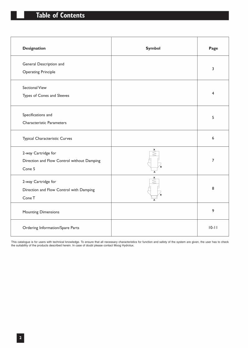
Table of Contents
2
Designation Symbol Page
General Description and
Operating Principle
Sectional View
Types of Cones and Sleeves
Specifications and
Characteristic Parameters
Typical Characteristic Curves
2-way Cartridge for
Direction and Flow Control without Damping
Cone S
2-way Cartridge for
Direction and Flow Control with Damping
Cone T
Mounting Dimensions
Ordering Information/Spare Parts
4
5
6
X
B
A
3
7
8
9
10-11
A
B
X
This catalogue is for users with technical knowledge. To ensure that all necessary characteristics for function and safety of the system are given, the user has to checkthe suitability of the products described herein. In case of doubt please contact Moog Hydrolux.
111841_MOOG_Hiflow 28/10/04 18:37 Seite 3
General Description and Operating Principle
3
General Description
Cartridge valves, also known as 2/2–way valves or logic valves,conform to DIN 24342 and ISO 7368 standards.They have twooperational ports A and B.The flow path between these twoconnections is controlled hydraulically by a pilot pressureapplied to X.
Depending on the control input, cartridge valves canbe used as:
➣ Directional Control Valves (start, stop, directional control)
➣ Flow Control ValvesThe preferred mode of mounting is the manifold block,
which can be equipped with several valves depending on thehydraulic circuit for the specific application. Each valve isconnected to each other in the manifold block.
The Moog Hydrolux product line contains valves ofnominal bores 16, 25, 32, 40, 50, 63, 80 and 100 as per DIN24342,for flows up to 12,000 lpm. Moreover, Moog Hydrolux offerscover plates and pilot valves for a wide variety of functions.
In addition to this, our product offering also containscartridge housings for a great number of applications forsubplate, pipe and flange mounting.
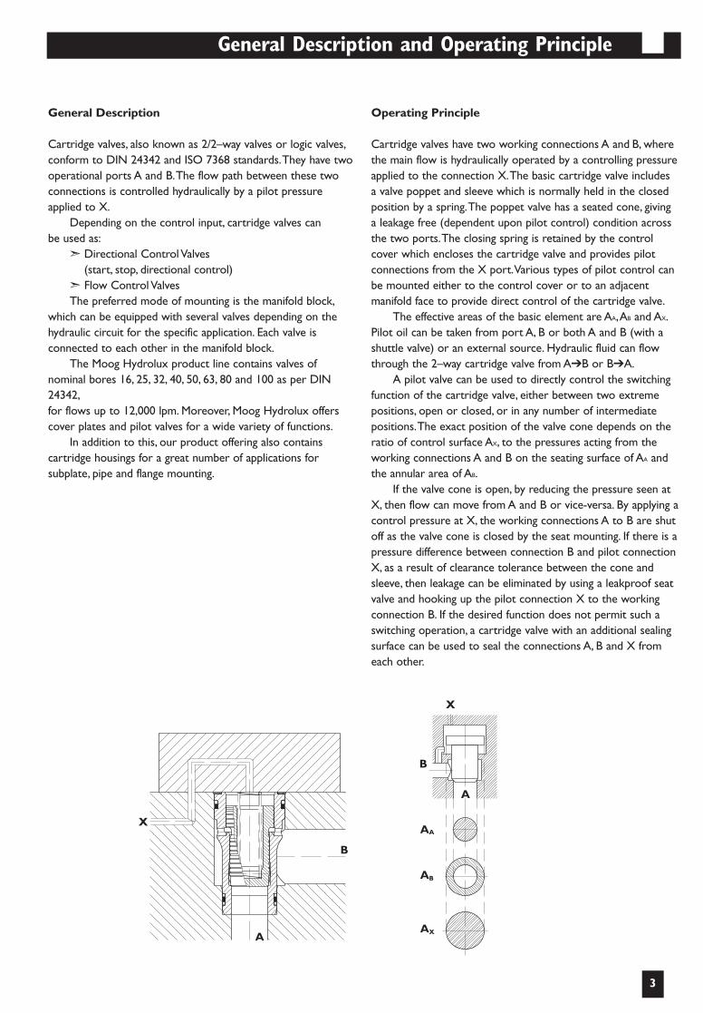
Operating Principle
Cartridge valves have two working connections A and B, wherethe main flow is hydraulically operated by a controlling pressureapplied to the connection X.The basic cartridge valve includesa valve poppet and sleeve which is normally held in the closedposition by a spring.The poppet valve has a seated cone, givinga leakage free (dependent upon pilot control) condition acrossthe two ports.The closing spring is retained by the controlcover which encloses the cartridge valve and provides pilotconnections from the X port.Various types of pilot control canbe mounted either to the control cover or to an adjacentmanifold face to provide direct control of the cartridge valve.
The effective areas of the basic element are AA,AB and AX.Pilot oil can be taken from port A, B or both A and B (with ashuttle valve) or an external source. Hydraulic fluid can flowthrough the 2–way cartridge valve from A➔B or B➔A.
A pilot valve can be used to directly control the switchingfunction of the cartridge valve, either between two extremepositions, open or closed, or in any number of intermediatepositions.The exact position of the valve cone depends on theratio of control surface AX, to the pressures acting from theworking connections A and B on the seating surface of AA andthe annular area of AB.
If the valve cone is open, by reducing the pressure seen atX, then flow can move from A and B or vice-versa. By applying acontrol pressure at X, the working connections A to B are shutoff as the valve cone is closed by the seat mounting. If there is apressure difference between connection B and pilot connectionX, as a result of clearance tolerance between the cone andsleeve, then leakage can be eliminated by using a leakproof seatvalve and hooking up the pilot connection X to the workingconnection B. If the desired function does not permit such aswitching operation, a cartridge valve with an additional sealingsurface can be used to seal the connections A, B and X fromeach other.
X
X
A
AB
AX
AA
B
B
A
111841_MOOG_Hiflow 8/6/03 7:23 PM Seite 6

Sectional View
4
High Flow Cartridge Valve Advantages
➢ 40% to 50% more flow with the same size of the DIN 24342 cartridge, relative to standard cartridge valves
➢ In many applications, the DIN 24342 cartridgecan be reduced one size
➢ Fully interchangeable with DIN 24342 cavity;no manifold redesign required
Cone
Sleeve-B, Cone-S Sleeve-B, Cone-T
Sleeve
Directional Control and Flow Control Valves
Types of Cones and Sleeves
111841_MOOG_Hiflow 8/13/03 7:33 AM Seite 7
Specifications
5
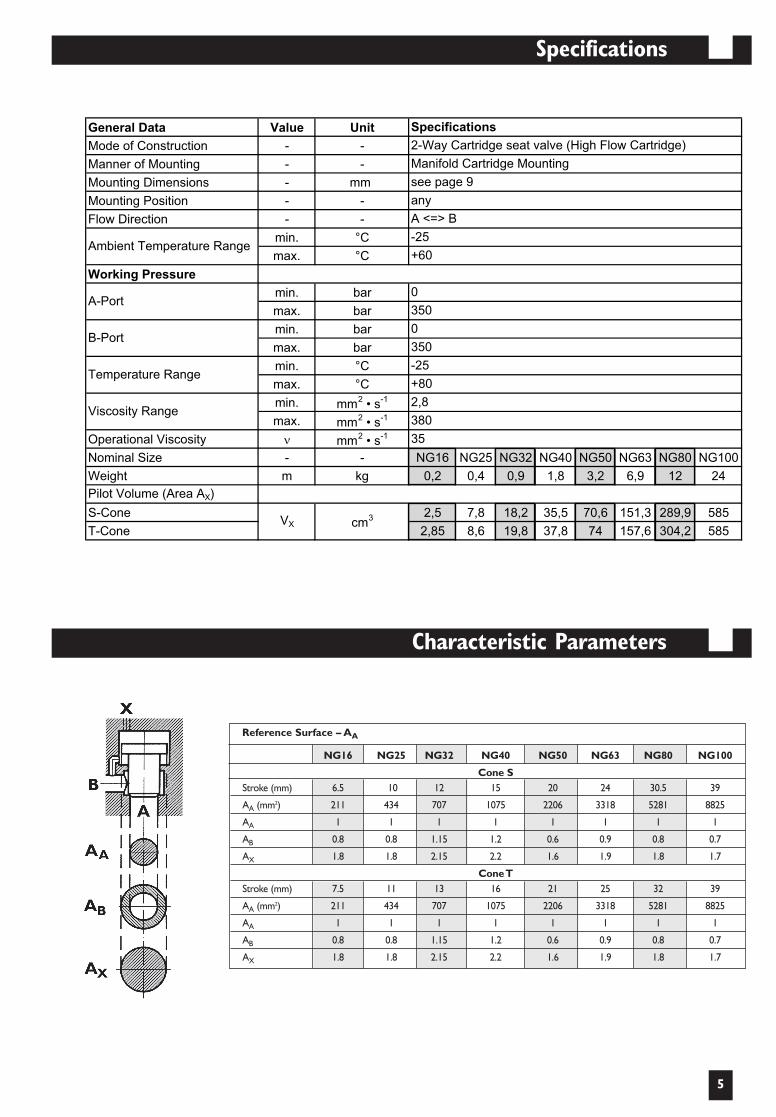
NG16 NG25 NG32 NG40 NG50 NG63 NG80 NG100
Cone SStroke (mm) 6.5 10 12 15 20 24 30.5 39
AA (mm2) 211 434 707 1075 2206 3318 5281 8825
AA 1 1 1 1 1 1 1 1
AB 0.8 0.8 1.15 1.2 0.6 0.9 0.8 0.7
AX 1.8 1.8 2.15 2.2 1.6 1.9 1.8 1.7
Cone TStroke (mm) 7.5 11 13 16 21 25 32 39
AA (mm2) 211 434 707 1075 2206 3318 5281 8825
AA 1 1 1 1 1 1 1 1
AB 0.8 0.8 1.15 1.2 0.6 0.9 0.8 0.7
AX 1.8 1.8 2.15 2.2 1.6 1.9 1.8 1.7
Reference Surface – AA
Characteristic Parameters
111841_MOOG_Hiflow 8/6/03 7:23 PM Seite 10
General Data Value Unit
Mode of Construction - -
Manner of Mounting - -
Mounting Dimensions - mm
Mounting Position - -
Flow Direction - -
min. °C
max. °C
Working Pressure
min. bar
max. bar
min. bar
max. bar
min. °C
max. °C
min. mm2 • s
-1
max. mm2 • s
-1
Operational Viscosity mm2 • s
-1
Nominal Size - - NG16 NG25 NG32 NG40 NG50 NG63 NG80 NG100
Weight m kg 0,2 0,4 0,9 1,8 3,2 6,9 12 24
Pilot Volume (Area AX)
S-Cone 2,5 7,8 18,2 35,5 70,6 151,3 289,9 585
T-Cone 2,85 8,6 19,8 37,8 74 157,6 304,2 585
Temperature Range-25
350A-Port
B-Port
+80
0
350
Viscosity Range
Specifications
Ambient Temperature Range
2-Way Cartridge seat valve (High Flow Cartridge)
see page 9
Manifold Cartridge Mounting
0
+60
-25
A <=> B
any
35
380
2,8
VX cm3

10
9
8
7
6
5
4
3
2
1
0
10
9
8
7
6
5
4
3
2
1
0
10
9
8
7
6
5
4
3
2
1
0
10
9
8
7
6
5
4
3
2
1
0
0 100 200 300 400 500 600 700 800 900 1000 0 250 500 750 1000 1250 1500 1750 2000 2250 2500
0 750 1500 2250 3000 3750 4500 5250 6000 6750 7500 0 1500 3000 4500 6000 7500 9000 10500 12000 13500 15000
PR
ES
SU
RE
DR
OP
- b
ar
FLOW - l/min
PR
ES
SU
RE
DR
OP
- b
ar
FLOW - l/min
PR
ES
SU
RE
DR
OP
- b
ar
PR
ES
SU
RE
DR
OP
- b
ar
FLOW - l/min FLOW - l/min
NG
16
(T C
one)
NG
16
(S C
one)
NG
25
(T C
one)
NG
25
(S C
one)
NG
32
(T C
one)
NG
32
(S C
one)
NG
40
(T C
one)
NG
40
(S C
one)
NG
50
(T C
one)
NG
50
(S C
one)
NG
63
(T C
one)
NG
63
(S C
one)
NG
80
(T C
one)
NG
80
(S C
one)
NG
100
(T C
one)
NG
100
(T C
one)
NG16/NG25 ∆p-Q-Curves
Flow direction: A B
NG32/NG40 ∆p-Q-Curves
Flow direction: A B
NG80/NG100 ∆p-Q-Curves
Flow direction: A B
NG50/NG63 ∆p-Q-Curves
Flow direction: A B
Typical Characteristic Curves
6
Notes:1. Performance characteristics are based
on oil viscosity of 32 cSt.
2. Oil temperature – 40°C.
3. Pressure drop vs. flow data measuredwithout spring.
Flow and Direction Functions (S & T Cones)
111841_MOOG_Hiflow 8/6/03 7:23 PM Seite 11
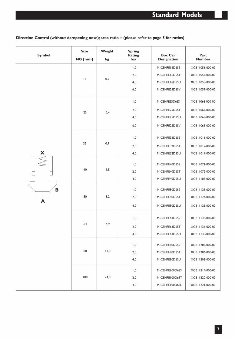
Standard Models
7
X
B
A
Direction Control (without dampening nose); area ratio = (please refer to page 5 for ratios)
1,0 M-CEHFE16D6SS XCB11056-000-00
2,0 M-CEHFE16D6ST XCB11057-000-00
4,0 M-CEHFE16D6SU XCB11058-000-00
6,0 M-CEHFE25D6SV XCB11059-000-00
1,0 M-CEHFE25D6SS XCB11066-000-00
2,0 M-CEHFE25D6ST XCB11067-000-00
4,0 M-CEHFE25D6SU XCB11068-000-00
6,0 M-CEHFE25D6SV XCB11069-000-00
1,0 M-CEHFE32D6SS XCB11016-000-00
2,0 M-CEHFE32D6ST XCB11017-000-00
4,0 M-CEHFE32D6SU XCB11019-000-00
1,0 M-CEHFE40D6SS XCB11071-000-00
2,0 M-CEHFE40D6ST XCB11072-000-00
4,0 M-CEHFE40D6SU XCB11108-000-00
1,0 M-CEHFE50D6SS XCB11123-000-00
2,0 M-CEHFE50D6ST XCB11124-000-00
4,0 M-CEHFE50D6SU XCB11125-000-00
1,0 M-CEHFE63D6SS XCB11135-000-00
2,0 M-CEHFE63D6ST XCB11136-000-00
4,0 M-CEHFE63D6SU XCB11138-000-00
1,0 M-CEHFE80D6SS XCB11205-000-00
2,0 M-CEHFE80D6ST XCB11206-000-00
4,0 M-CEHFE80D6SU XCB11208-000-00
1,0 M-CEHFE100D6SS XCB11219-000-00
2,0 M-CEHFE100D6ST XCB11220-000-00
3,0 M-CEHFE100D6SL XCB11221-000-00
Size Weight SpringSymbol Rating Box Car Part
NG [mm] kg bar Designation Number
16 0,2
25 0,4
32 0,9
40 1,8
50 3,2
63 6,9
80 12,0
100 24,0
111841_MOOG_Hiflow 8/6/03 7:23 PM Seite 12

Standard Models
8
Direction Control (with dampening nose); area ratio = (please refer to page 5 for ratios)
A
B
X
Size Weight SpringSymbol Rating Box Car Part
NG [mm] kg bar Designation Number
1,0 M-CEHFE16D6TS XCB11188-000-00
2,0 M-CEHFE16D6TT XCB11189-000-00
4,0 M-CEHFE16D6TU XCB11190-000-00
6,0 M-CEHFE25D6TV XCB11191-000-00
1,0 M-CEHFE25D6TS XCB11183-000-00
2,0 M-CEHFE25D6TT XCB11184-000-00
4,0 M-CEHFE25D6TU XCB11185-000-00
6,0 M-CEHFE25D6TV XCB11186-000-00
1,0 M-CEHFE32D6TS XCB11149-000-00
2,0 M-CEHFE32D6TT XCB11150-000-00
4,0 M-CEHFE32D6TU XCB11151-000-00
1,0 M-CEHFE40D6TS XCB11118-000-00
2,0 M-CEHFE40D6TT XCB11119-000-00
4,0 M-CEHFE40D6TU XCB11217-000-00
1,0 M-CEHFE50D6TS XCB11099-000-00
2,0 M-CEHFE50D6TT XCB11100-000-00
4,0 M-CEHFE50D6TU XCB11101-000-00
1,0 M-CEHFE63D6TS XCB11141-000-00
2,0 M-CEHFE63D6TT XCB11142-000-00
4,0 M-CEHFE63D6TU XCB11144-000-00
1,0 M-CEHFE80D6TS XCB11211-000-00
2,0 M-CEHFE80D6TT XCB11212-000-00
4,0 M-CEHFE80D6TU XCB11214-000-00
1,0 M-CEHFE100D6TS XCB11224-000-00
2,0 M-CEHFE100D6TT XCB11225-000-00
3,0 M-CEHFE100D6TL XCB11226-000-00
16 0,2
25 0,4
32 0,9
40 1,8
50 3,2
63 6,9
80 12,0
100 24,0
111841_MOOG_Hiflow 8/6/03 7:23 PM Seite 9
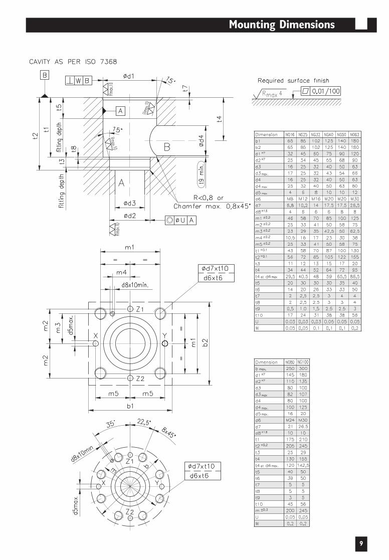
Mounting Dimensions
9
111841_MOOG_Hiflow 8/6/03 7:23 PM Seite 8
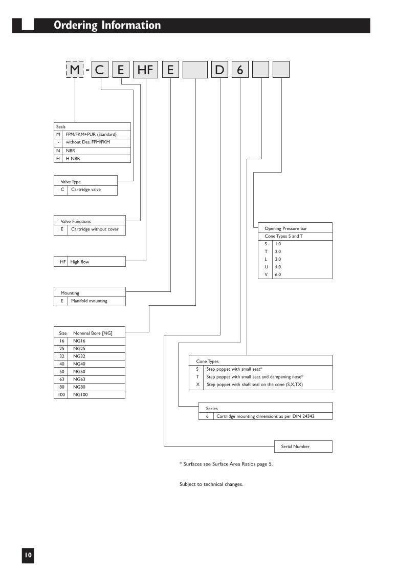
Ordering Information
10
Valve Type
C Cartridge valve
Valve Functions
E Cartridge without cover
HF High flow
Mounting
E Manifold mounting
Size Nominal Bore [NG]
16 NG16
25 NG25
32 NG32
40 NG40
50 NG50
63 NG63
80 NG80
100 NG100
Opening Pressure bar
Cone Types S and T
S 1,0
T 2,0
L 3,0
U 4,0
V 6,0
Cone Types
S Step poppet with small seat*
T Step poppet with small seat and dampening nose*
X Step poppet with shaft seal on the cone (S,X,TX)
Serial Number
Series
6 Cartridge mounting dimensions as per DIN 24342
* Surfaces see Surface Area Ratios page 5.
Subject to technical changes.
CM E EHF D 6-
Seals
M FPM/FKM+PUR (Standard)
- without Des. FPM/FKM
N NBR
H H-NBR
111841_MOOG_Hiflow 8/6/03 7:23 PM Seite 5
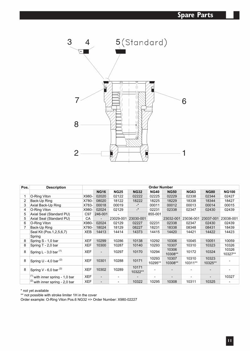
Spare Parts
11
3 4
7
8
2 1
6
5
Pos. DescriptionNG16 NG25 NG32 NG40 NG50 NG63 NG80 NG100
1 O-Ring Viton X980- 02020 02122 02222 02225 02229 02338 02344 024272 Back-Up Ring X780- 08020 18122 18222 18225 18229 18338 18344 184273 Axial Back-Up Ring X783- 00018 00019 -* 00011 00012 00013 00014 000154 O-Ring Viton X980- 02024 02129 -* 02231 02338 02347 02430 024395 Axial Seal (Standard PU) C97 246-001 - 855-0015 Axial Seal (Standard PU) CA - 23029-001 23030-001 23032-001 23036-001 23037-001 23038-0016 O-Ring Viton X980- 02024 02129 02227 02231 02338 02347 02430 024397 Back-Up Ring X780- 18024 18129 08227 18231 18338 08348 08431 18439
Seal Kit (Pos.1,2,5,6,7) XEB 14413 14414 14373 14415 14420 14421 14422 14423Spring
8 Spring S - 1,0 bar XEF 10299 10286 10138 10292 10306 10045 10051 100598 Spring T - 2,0 bar XEF 10300 10287 10140 10293 10307 10310 10323 10326
(1) with inner spring - 1,0 bar XEF - - - - - - - 10327(2) with inner spring - 2,0 bar XEF - - 10322 10295 10308 10311 10325 -
** not possible with stroke limiter 1H in the coverOrder example: O-Ring Viton Pos.6 NG32 => Order Number: X980-02227
1032610327**
-
-
* not yet available
-
10324
1032310325**
-
Spring L - 3,0 bar (1)8
8 Spring U - 4,0 bar (2)
XEF
XEF
-
10301
10297
8 Spring V - 6,0 bar (2) XEF 10302 10289
10170
10171
1017110322**
Order Number
10294
1029310295**
-
1030610308**10307
10308**
-
10172
1031010311**
10288
X999_02010_MOOG 28/10/04 18:45 Seite 4

AustraliaBrazilChina
DenmarkEnglandFinlandFrance
GermanyIndiaIrelandItaly
JapanKoreaLuxembourg PhilippinesSingaporeSpainSwedenUSA
MOOG HYDROLUX S.àr.l.1, rue de l’AciérieL-1112 LUXEMBOURGTel: (+352) 40 46 40-1Fax: (+352) 40 46 40-909E-mail: [email protected]
10/04/X999-02010
111841_MOOG_Hiflow_Cover 8/12/03 7:58 AM Seite 1