high head centrifugal pedestal pumps information and repair parts manual 4897, 4906 and 4907...
TRANSCRIPT

Specifications Information and Repair Parts Manual 4897, 4906 and 4907
4897-251-00 1 8/2014
Please read and save this Repair Parts Manual. Read this manual and the General Operating Instructions carefully before attempting to assemble, install, operate or maintain the product described. Protect yourself and others by observing all safety information. The Safety Instructions are contained in the General Operating Instructions. Failure to comply with the safety instructions accompanying this product could result in personal injury and/or property damage! Retain instructions for future reference. AMT reserves the right to discontinue any model or change specifications at any time without incurring any obligation.
©2014 American Machine & Tool Co., Inc. of PA, A Subsidiary of The Gorman-Rupp Company, All Rights Reserved.
Periodic maintenance and inspection is required on all pumps to ensure proper operation. Unit must be clear of debris and sediment. Inspect for leaks and loose bolts. Failure to do so voids warranty.
High Head Centrifugal Pedestal PumpsRefer to pump manual 1808-634-00 for General Operating and Safety Instructions.
MAINTENANCE
Make certain that the unit is disconnected from the power source before attempting to service or remove any components!
REMOVAL OF OLD SEALShould the mechanical seal (Ref. No. 6) require replacement, proceed as follows and refer to Figures No. 1 and 2.
IMPORTANT: Always replace both the seal seat and seal head to ensure proper mating of components! Also, the impeller seal (Ref. No. 9) should be replaced any time the impeller lock nut (Ref. No. 10) has been removed.1. Remove four bolts (Ref. No. 3) connecting the casing (Ref. No. 11) to the
adapter (Ref. No. 4).2. Remove the casing.
Care should be taken not to “pinch” or “shave” the O-ring gasket (Ref. No. 5) between the adapter and the casing.3. Use a box and/or socket wrench to remove the impeller nut (Ref. No.10).
Remove the impeller seal (Ref. No. 9) and the impeller (Ref. No. 8).NOTE: Pump shaft must be held in place to remove impeller. Impeller (Ref. No. 8) and lock nut (Ref. No. 10) unscrew CCW when looking at the front of the pump.4. The seal head (part of Ref. No. 6) can now be pulled from the shaft. (See
Figure 2).5. Pry the seal seat (part of Ref. No. 6) from the adapter (Ref. No. 4). (See
Figure 2).
INSTALLATION OF NEW SEAL
The precision faces on the mechanical seal are easily damaged. Handle your replacement seal carefully. Do not touch the carbon/ceramic seal faces.
IMPORTANT: Be sure that shaft shoulder does not damage carbon face.1. Thoroughly clean all surfaces of the seal seat cavity in adapter (Ref. No.
4).2. Using a clean cloth, wipe the shaft and shaft sleeve to make certain that
they are perfectly clean.3. Wet the rubber portion of the new seal seat (part of Ref. No. 6) with a light
coating of soapy water. While wearing clean gloves or using a clean light rag, press seal seat squarely into adapter recess. Place the cardboard washer (usually supplied with new seal) over the polished surface and use a piece of pipe or dowel rod to press in firmly, but gently. Avoid scratching the white ceramic face.
4. Dispose of cardboard washer. Check again to see that ceramic surface is free of dirt and all other foreign particles and that it has not been scratched or damaged.
5. Wet the inside rubber portion of the new seal head 9 part of Ref. No. 6) with a light coating of soapy water. Slide head onto the motor shaft with the sealing surface (Carbon) facing the seal seat (See Figure 1). This completes seal installation.
NOTE: A short “run-in” period may be necessary to provide completely leakproof seal operation.
Rotation (Threaded Shaft Model) 1. Remove pump components from pedestal assembly:
a. Remove bolts (Ref. No. 3) from casing; remove casing and o-ring (Ref. No. 5).
b. Remove impeller nut (Ref. No.10), unscrew CCW. Pedestal shaft must be held in place to loosen nut.
c. Remove impeller o-ring (Ref. No. 9) and impeller (Ref. No. 8) turning CCW while holding pedestal shaft in place. Remove impeller shims (Ref.No. 7).
d. Replace seal as described in “Removal of Old Seal”.e. Remove bolts (Ref. No. 13); remove adapter.
Reverse instructions to install pump on repaired pedestal assembly.
Failure to follow above information may cause impeller to unscrew and damage pump head, cause property damage and/or personal injury.
DESCRIPTIONThese pumps are non self-priming units designed for use where higher heads are required to handle liquid transfer, heating and cooling applications where no suction lift is required. Pump construction features investment cast stainless steel closed impeller. The discharge port on all models can be rotated in 90º incre-ments to accommodate specific applications. All units are for use with non-flammable liquids compatible with pump component materials. Units are suitable for direct coupling or pulley drive. Pump rotation is CCW facing the front of the pump. No motor is supplied with these units.
Figure 1 - Mechanical Seal
Specifications Information and Repair Parts Manual 4897, 4906 and 4907
4897-251-00 2 8/2014
PEDESTAL ASSEMBLY MAINTENANCE
Disconnect from power source before servicing or inspecting pump for any reason.
Bearing Housing Service
1. Remove shaft bearings (Ref. No. 3) and shaft (Ref. No. 4) as an assembly by first removing snap ring (Ref. No. 6) then wave washer (Ref. No. 5).
2. Push shaft/bearing assembly out of bearing housing (Ref. No. 2) by rapping on pump end of shaft with soft mallet or block of wood and a hammer.
3. Shaft bearings can now be removed from shaft.4. If shaft bearings have been removed from shaft and bearing housing,
replace by sliding bearing or shaft to shoulder.5. Replace shaft bearing assembly by sliding assembly into housing, pump
end first. Push shaft bearing assembly completely in by gently tapping on key way end of shaft with soft mallet.
6. Replace wave washer and snap ring.7. Reassemble pump to pedestal (See pump manual “Maintenance”)
High Head Centrifugal Pedestal Pumps
Specifications Information and Repair Parts Manual 4897, 4906 and 4907
4897-251-00 3 8/2014
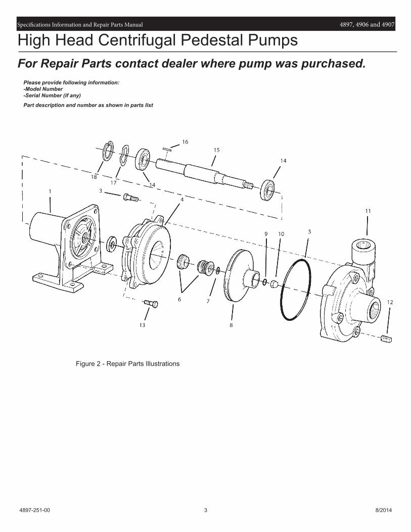
For Repair Parts contact dealer where pump was purchased.Please provide following information:-Model Number-Serial Number (if any)
Part description and number as shown in parts list
Figure 2 - Repair Parts Illustrations
High Head Centrifugal Pedestal Pumps

Specifications Information and Repair Parts Manual 4897, 4906 and 4907
4897-251-00 4 8/2014
Ref Part Number for Models
No. Description 4897 4906 4907 Qty
1 Pedestal/Bearing Housing 3890-090-09 3890-090-09 3890-090-09 1
Pedestal Assembly 3891-999-99 3891-999-99 3891-999-99 1
(includes Ref. Nos. 1, 14, 15, 16, 17, 18 and 19)
3 3/8-16 x 1" Hex Head Cap Screw * * * 4
4 Adapter Kit - Cast Iron 4890-030-95 4900-030-95 4900-030-95 1
Adapter Kit - Bronze 4890-030-97 4900-030-97 4900-030-97 1
Adapter Kit - Stainless Steel 4890-030-98 4900-030-98 4900-030-98
(includes Ref. Nos. 4 and 13)
5 O-Ring - Buna N Incl. w/Ref KIT Incl. w/Ref KIT Incl. w/Ref KIT 1
O-Ring - Viton Incl. w/Ref KIT Incl. w/Ref KIT Incl. w/Ref KIT 1
6 Seal Assembly - Buna N 1640-161-96 1640-161-96 1640-161-96 1
Seal Assembly - Viton 1640-161-97 1640-161-97 1640-161-97 1
7 Impeller Shim Kit 1806-044-90 1806-044-90 1806-044-90 1
8 Impeller Kit 4891-010-98 4901-010-98 4905-010-98 1
(includes Ref. Nos. 7, 8 and 10)
9 O-Ring - Buna N Incl. w/Ref KIT Incl. w/Ref KIT Incl. w/Ref KIT 1
O-Ring - Viton Incl. w/Ref KIT Incl. w/Ref KIT Incl. w/Ref KIT 1
10 7/16-20 Acorn Nut 1784-001-00 1784-001-00 1784-001-00 1
11 Casing Kit - Cast Iron 4890-001-95 4900-001-95 4900-001-95 1
Casing Kit - Bronze 4890-001-97 4900-001-97 4900-001-97 1
Casing Kit - Stainless Steel 4890-001-98 4900-001-98 4900-001-97 1
(includes Ref. Nos. 3, 11 and 12)
12 3/8" Pipe Plug * * * 1
13 3/8 x 3/4" Hex Head Cap Screw * * * 4
14 Ball Bearing 1695-031-00 1695-031-00 1695-031-00 2
15 Shaft 1696-066-00 1696-066-00 1696-066-00 1
16 Shaft Key 1517-000-00 1517-000-00 1517-000-00 1
17 Wave Washer 1806-023-00 1806-023-00 1806-023-00 1
18 Snap Ring 1695-034-00 1695-034-00 1695-034-00 1
19 q Bearing Shim Kit 1696-008-90 1696-008-90 1696-008-90 1
20 1696-075-00 Thread Sealant 1696-075-00 1696-075-00 1696-075-00 1
KIT O-Ring Kit - Buna N 4890-300-90 4900-300-90 4900-300-90 1
O-Ring Kit - Viton 4890-301-90 4900-301-90 4900-301-90 1
(*) Standard hardware item, available locally.
q Not Shown
Repair Parts List

Specifications Information and Repair Parts Manual 4897, 4906 and 4907
4897-251-00 5 8/2014
NOTES:

Specifications Information and Repair Parts Manual 4897, 4906 and 4907
4897-251-00 6 8/2014
NOTES:

www.amtpump.com