high on control big on reliability
TRANSCRIPT
CBM
C/P
RD/1
1201
4SP
507
01
AC Drive for Elevator
High on controlbig on reliability
Three Phase 230V (2.2 ~ 37kW)
Three Phase 415V (2.2 ~ 45kW)
Customer Interaction Center (CIC)BSNL / MTNL (toll free): 1800 233 5858 Reliance (toll free): 1800 200 5858 Tel: 022 6774 5858 Fax: 022 6774 5859 Email: [email protected] Web: www.Lntebg.com
Larsen & Toubro Limited, Electrical Standard ProductsPowai Campus, Mumbai 400 072
Regd. Office: L&T House, N. M. Marg, Ballard Estate, Mumbai - 400 001. INDIA Tel: +91 22 6752 5656 CIN: L99999MH1946PLC004768
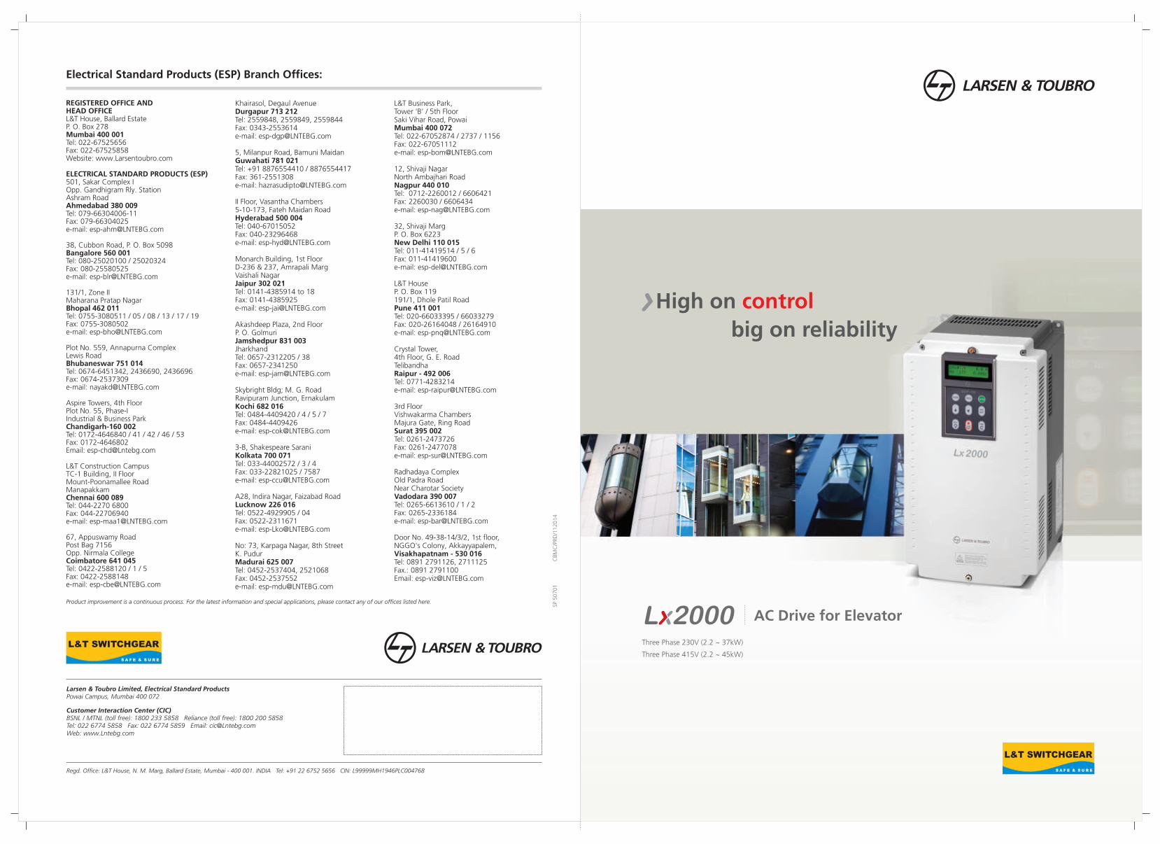
Electrical Standard Products (ESP) Branch Offices:
Product improvement is a continuous process. For the latest information and special applications, please contact any of our offices listed here.
Khairasol, Degaul AvenueDurgapur 713 212Tel: 2559848, 2559849, 2559844Fax: 0343-2553614e-mail: [email protected]
5, Milanpur Road, Bamuni MaidanGuwahati 781 021Tel: +91 8876554410 / 8876554417Fax: 361-2551308e-mail: [email protected]
II Floor, Vasantha Chambers5-10-173, Fateh Maidan RoadHyderabad 500 004Tel: 040-67015052Fax: 040-23296468e-mail: [email protected]
Monarch Building, 1st FloorD-236 & 237, Amrapali MargVaishali NagarJaipur 302 021Tel: 0141-4385914 to 18Fax: 0141-4385925e-mail: [email protected]
Akashdeep Plaza, 2nd FloorP. O. GolmuriJamshedpur 831 003JharkhandTel: 0657-2312205 / 38Fax: 0657-2341250e-mail: [email protected]
Skybright Bldg; M. G. RoadRavipuram Junction, ErnakulamKochi 682 016Tel: 0484-4409420 / 4 / 5 / 7Fax: 0484-4409426e-mail: [email protected]
3-B, Shakespeare SaraniKolkata 700 071Tel: 033-44002572 / 3 / 4 Fax: 033-22821025 / 7587e-mail: [email protected]
A28, Indira Nagar, Faizabad Road Lucknow 226 016Tel: 0522-4929905 / 04Fax: 0522-2311671e-mail: [email protected]
No: 73, Karpaga Nagar, 8th StreetK. PudurMadurai 625 007Tel: 0452-2537404, 2521068Fax: 0452-2537552e-mail: [email protected]
REGISTERED OFFICE AND HEAD OFFICEL&T House, Ballard EstateP. O. Box 278Mumbai 400 001Tel: 022-67525656 Fax: 022-67525858Website: www.Larsentoubro.com
ELECTRICAL STANDARD PRODUCTS (ESP)501, Sakar Complex I Opp. Gandhigram Rly. Station Ashram RoadAhmedabad 380 009Tel: 079-66304006-11Fax: 079-66304025e-mail: [email protected]
38, Cubbon Road, P. O. Box 5098Bangalore 560 001Tel: 080-25020100 / 25020324Fax: 080-25580525e-mail: [email protected]
131/1, Zone IIMaharana Pratap NagarBhopal 462 011Tel: 0755-3080511 / 05 / 08 / 13 / 17 / 19 Fax: 0755-3080502e-mail: [email protected]
Plot No. 559, Annapurna ComplexLewis RoadBhubaneswar 751 014Tel: 0674-6451342, 2436690, 2436696Fax: 0674-2537309e-mail: [email protected]
Aspire Towers, 4th FloorPlot No. 55, Phase-IIndustrial & Business ParkChandigarh-160 002Tel: 0172-4646840 / 41 / 42 / 46 / 53Fax: 0172-4646802Email: [email protected]
L&T Construction CampusTC-1 Building, II FloorMount-Poonamallee RoadManapakkamChennai 600 089Tel: 044-2270 6800Fax: 044-22706940e-mail: [email protected]
67, Appuswamy RoadPost Bag 7156 Opp. Nirmala CollegeCoimbatore 641 045Tel: 0422-2588120 / 1 / 5Fax: 0422-2588148e-mail: [email protected]
L&T Business Park,Tower 'B' / 5th FloorSaki Vihar Road, PowaiMumbai 400 072Tel: 022-67052874 / 2737 / 1156Fax: 022-67051112e-mail: [email protected]
12, Shivaji NagarNorth Ambajhari RoadNagpur 440 010Tel: 0712-2260012 / 6606421Fax: 2260030 / 6606434e-mail: [email protected]
32, Shivaji Marg P. O. Box 6223New Delhi 110 015Tel: 011-41419514 / 5 / 6Fax: 011-41419600e-mail: [email protected]
L&T House P. O. Box 119 191/1, Dhole Patil RoadPune 411 001Tel: 020-66033395 / 66033279Fax: 020-26164048 / 26164910e-mail: [email protected]
Crystal Tower, 4th Floor, G. E. RoadTelibandhaRaipur - 492 006Tel: 0771-4283214e-mail: [email protected]
3rd Floor Vishwakarma ChambersMajura Gate, Ring RoadSurat 395 002Tel: 0261-2473726Fax: 0261-2477078e-mail: [email protected]
Radhadaya ComplexOld Padra RoadNear Charotar SocietyVadodara 390 007Tel: 0265-6613610 / 1 / 2Fax: 0265-2336184e-mail: [email protected]
Door No. 49-38-14/3/2, 1st floor,NGGO's Colony, Akkayyapalem,Visakhapatnam - 530 016Tel: 0891 2791126, 2711125Fax.: 0891 2791100Email: [email protected]
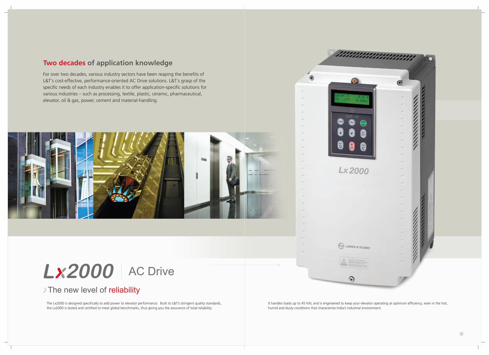
For over two decades, various industry sectors have been reaping the benefits of L&T's cost-effective, performance-oriented AC Drive solutions. L&T's grasp of the specific needs of each industry enables it to offer application-specific solutions for various industries � such as processing, textile, plastic, ceramic, pharmaceutical, elevator, oil & gas, power, cement and material-handling.
Two decades of application knowledge
The Lx2000 is designed specifically to add power to elevator performance. Built to L&T�s stringent quality standards, the Lx2000 is tested and certified to meet global benchmarks, thus giving you the assurance of total reliability.
It handles loads up to 45 kW, and is engineered to keep your elevator operating at optimum efficiency, even in the hot, humid and dusty conditions that characterise India�s industrial environment.
AC Drive
The new level of reliability
1

We believe in addressing your needs and not just selling a product. That's why a dedicated Solutions Team first focuses on understanding your application. Then helps you select the drive that best meets your needs. Our advice on installation, maintenance and replacement will ensure that your elevators function at peak productivity. From engineer to repair technician, our people have the knowledge and skill-sets to deliver total peace of mind.
Meeting solving your needs, your problems
A knowledge-based company, L&T brings you the benefits of over 75 years of engineering experience and expertise, and the richness of its collaborations with technology leaders across the globe.
For 50 years, L&T's low-tension switchgear � India's widest range � has been the preferred option of top industrial houses countrywide.
Backed by knowledge engineeringacross seven decades
32

Tested
NABL-Certified
E&A Lab
L&T is one of the few switchgear manufacturers in India with a dedicated, NABL-certified testing facility. Our products are tested for conformity to standards that exceed minimum requirements, giving you the assurance of high-quality performance. Our focus on continuous improvement ensures that our standards are on par with the best in the world. Repeat orders endorse the value that we deliver.
Tested. Certified. Reliable.
54

A malfunction of the drive can bring an entire assembly line or process to a halt. To ensure maximum uptime for you, our Rapid Response service team is available to analyze the situation and help you set the problem right. We have set up strategic service centres across the country to provide temporary replacement drives or ready spares to ensure that your business keeps running smoothly.
After-sales service aimed at maximum uptime
Rapid Response Service Team
Ready Spares
At our countrywide Switchgear Training Centres, we can train your operators, electricians and supervisors to increase their effectiveness in the operation and maintenance and trouble-shooting of your drives. We can also conduct in-plant training and workshops at your premises to improve both power management and equipment maintenance skills. This gives you total operational excellence, minimising downtime.
L&T's engineers and channel partners also upgrade their skills through seminars, workshops, training sessions and white papers on electrical practices.
Training your people to enhance your operations
76

Features
Lx2000 guarantees stable driving and monitoring of the elevator with both optimum speed pattern and position control.
Rollback Prevention:Anti-Rollback Function(without external load cell)
Green : Posion Error between Command & Actual Spd.
Before Anti-Rollback Algorithm After Anti-Rollback Algorithm
Time Chart for Anti-Rollback Function
Elevator DriveFeatures
Elevator Drive
Suitable for geared / gearless machines
Compatibility with various types of encoders
Anti-roll-back algorithm
Load and direction based floor-leveling
Built-in ARD function
Features that ensure performance
Provides Dedicated Solutionsfor Elevator Systems
Controls the elevator systemsmoothly and efficiently
98

Features
The SIN/COS encoder option enablesmore precise control over a normal encoder.
Extreme control precise
SIN/COS encoder option
With synchronous motor sensorlesscontrol functions including initial stimulusposition estimation, the Lx2000 perfectlycontrols the SPM and IPM motor - withoutan additional sensor.
� SPM, IPM motor� Within ±5� error estimation� 30,000 rpm driving fast response within 100msec
SPM, IPM motor control
Elevator Drive
Auto-tuningStandstill auto-tuningL&T�s unique technology allows auto-tuning to be performedeven with the motor shaft directly connected to the load.Standstill auto-tuning is useful for elevators because it does notrequire removal of the brake coupling connected to the motor.
To minimize risk of the elevator�s givingin to the gravitational pull of the earth, brake-control is built in.
Built-in brake control for vertical loading safe
Rotationel auto-tuningWidely used for vector-control drives, this requiresthe motor shaft to be free from the couplingfor proper operation.
Precise ControlPrecise speed controlAccurate control with SIN/COS encoderPM Sensorless controlStationary Auto tuning (at standstill)Brake Control
1110

PC-based Software for Easy Maintenance of Drive and Motor Parameters
DriveConnect software allows drive/system monitoring on a PC and easy maintenance of drive and motor parameters
� Windows-based graphic user interface (GUI]� Modbus-RTU� Connecting up to 31 drives � Integrated control console� Offline editing function� Data upload/download� 4-channel oscilloscope� Trigger function
Easy-to-maintain drive/motor parameter via PC
User-FriendlyInterface
Easy-to-use with user-centrickeypad and removableterminal blocks
Supports communicationdevices such asModbus-RTU, CC-Link
Systematic and efficientsystem managementthrough DriveConnet 2.0
Converter
1312
User-Friendly DesignEasy-to-use keypadBy adopting a user-centered operationkeypad, parameter setting becomeseasier. When applying to the system,the varied information required canbe monitored.
International standardremovable terminal blockWiring and maintenance is made easyby an international standard acquiredterminal block.
Drive integrated console
Reporting 2
Parameter management
Oscilloscope/Trigger
DriveConnect
Reporting 1

Model & TypeElevator Drive Elevator Drive
Motor rating(Heavy Duty) Three-Phase 230V
2.2kW LTVF-L20012AAA LTVF-L40006AAA
3.7kW LTVF-L20016AAA LTVF-L40008AAA
5.5kW LTVF-L20024AAA LTVF-L40012AAA
7.5kW LTVF-L20032AAA LTVF-L40016AAA
11kW LTVF-L20046AAA LTVF-L40024AAA
15kW LTVF-L20059AAA LTVF-L40030AAA
18.5kW LTVF-L20074AAA LTVF-L40039AAA
22kW LTVF-L20088AAA LTVF-L40045AAA
30kW LTVF-L20122AAA LTVF-L40061AAA
37kW LTVF-L20146AAA LTVF-L40075AAA
45kW - LTVF-L40091AAA
Three-Phase 415V
Lx2000
L&T VariableFrequencyDrive
Series Input Voltage Enclosure
2 Three-Phase200~240[V]
4 Three-Phase380~480[V]
A IP00
LTVF L 4
Drive Current Rating
0012 A
Reserved
A
Reserved
A
Heavy Duty Amp
15
Digital Operator Instructions
Function
Shift between groups.
Shift from a group code to upper code.
Parameter setting value change.
Saving altered setting values.
Shift between codes and increase the parameter value.
Shift between codes and decrease the parameter value.
In case of set-up mode, it is operated with the shift key. Operation with ESC key innon-set up mode.
Reverse run key.
Stop key when drive is on operation.
Forward run key.
Turns on at reverse operation.
Blinks while the drive is on Acc/Deceleration and then turns on the constantspeed operation.
Turns off when drive stops operation.
Classification
KEY
LED Blinks when fault occurs.
Turns on during forward operation.
Acc/Deceleration running modes blink the lamp and it is turned on in the
Display
MODE
PROG
ENT
▲ (up)
▼ (down)
Shift/ESC
REV
STOP/RESET
FWD
(REV)
(STOP/RESET)
(FWD)
Function Name
Mode Key
Program Key
Enter Key
Up Key
Down Key
Shift/ESC Key
Reverse run
Stop/Reset Key
Forward Key
Reverse run key
Stop/Fault display
Forward Run Display
forward operation.
� Data and status display
� Shift between function groups� Shifting from group code to the upper code
� Function code shift� Shift to next function code
� Data increase in set up mode
� Reverse run command key � Only available, with loader
operation� LED is turned ON with reverse run� Blinks during Acc/Deceleration of reverse run
� Shift to function code� Shift to previous code
� Data is decreased in set up mode
MODE
REV
� Data set up start
� Data set up completion
� Decimal point shift� Only available in case of data setup
� Forward run command key� Only available with loader operation� LED is turned on with forward operation � Blinks during Acc/Deceleration of forward operation
� Stop command� Available with the loader operation� LED is turned on when drive stops its operation � Blinks when fault occurs � Reset� Fault reset
STOPRESET
FWD
SHITESC
ENT
PROG
Digital Operator
14
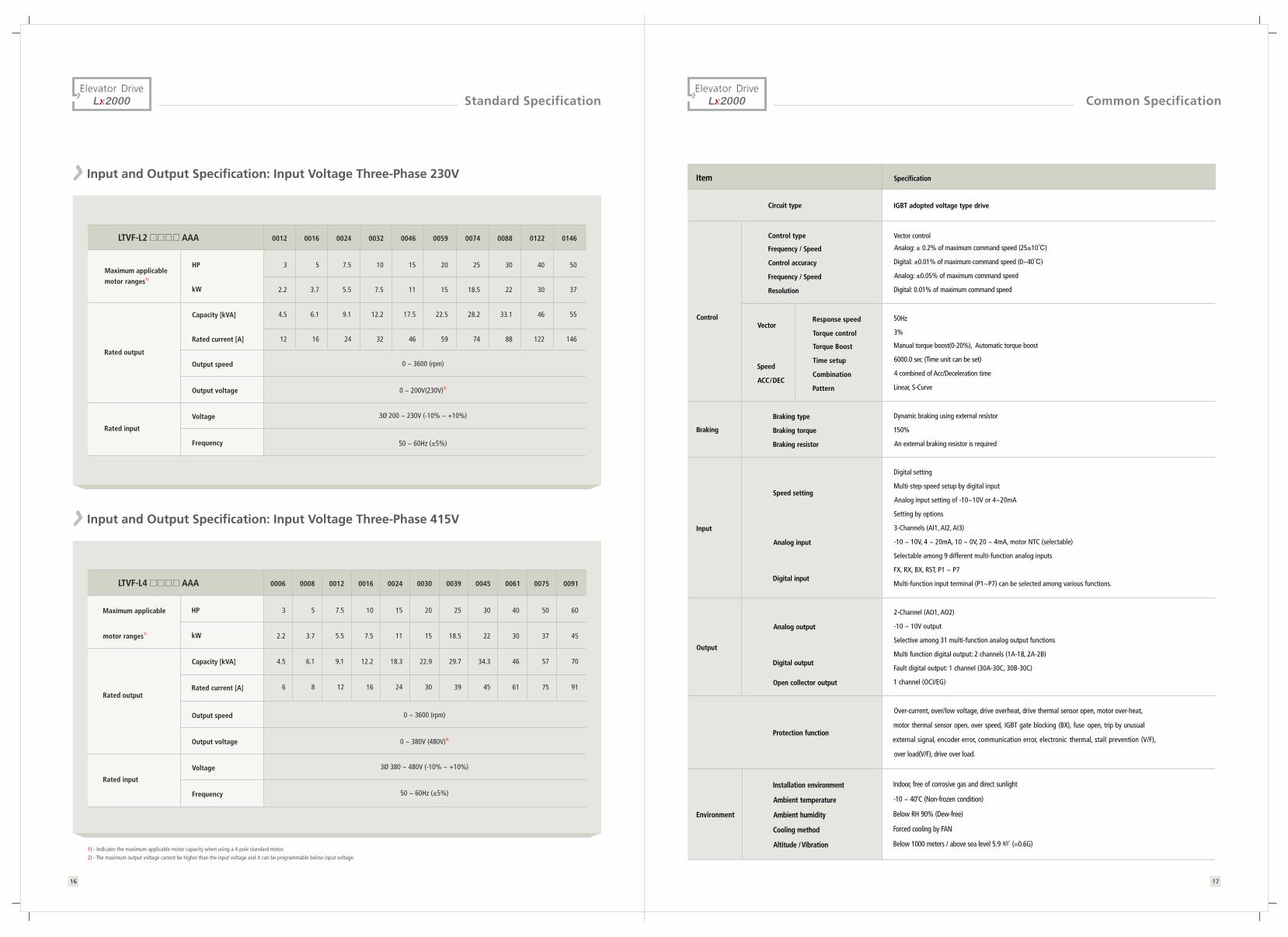
Common SpecificationStandard SpecificationElevator Drive Elevator Drive
Input and Output Specification: Input Voltage Three-Phase 230V
Rated output
HP
kW
Capacity [kVA]
Voltage
40
30
46
122
30
22
33.1
88
25
18.5
28.2
74
20
15
22.5
59
15
11
17.5
46
10
7.5
12.2
32
7.5
5.5
9.1
24
5
3.7
6.1
16
3
2.2
4.5
12
0 ~ 200V(230V)2)
3Ø 200 ~ 230V (-10% ~ +10%)
0 ~ 3600 (rpm)
Maximum applicablemotor ranges1)
Rated current [A]
Output speed
Output voltage
Frequency 50 ~ 60Hz (±5%)
0012 0016 0024 0032 0046 0059 0074 0088 0122LTVF-L2 AAA 0146
50
37
55
146
Rated input
Speed setting
Input
Output
Analog input
Digital input
Analog output
Digital output
Open collector output
Protection function
Installation environment
Ambient temperature
Ambient humidity
Cooling method
Altitude / Vibration
Environment
Response speed
Torque control
Torque Boost
Time setup
Combination
Pattern
Control type
Frequency / Speed
Control accuracy
Frequency / Speed
Resolution
Braking type
Braking torque
Braking resistor
Circuit type
Digital setting
Multi-step-speed setup by digital input
Analog input setting of -10~10V or 4~20mA
Setting by options
3-Channels (AI1, AI2, AI3)
-10 ~ 10V, 4 ~ 20mA, 10 ~ 0V, 20 ~ 4mA, motor NTC (selectable)
Selectable among 9 different multi-function analog inputs
FX, RX, BX, RST, P1 ~ P7
Multi-function input terminal (P1~P7) can be selected among various functions.
2-Channel (AO1, AO2)
-10 ~ 10V output
Selective among 31 multi-function analog output functions
Multi function digital output: 2 channels (1A-1B, 2A-2B)
Fault digital output: 1 channel (30A-30C, 30B-30C)
1 channel (OCI/EG)
Over-current, over/low voltage, drive overheat, drive thermal sensor open, motor over-heat,
motor thermal sensor open, over speed, IGBT gate blocking (BX), fuse open, trip by unusual
external signal, encoder error, communication error, electronic thermal, stall prevention (V/F),
over load(V/F), drive over load.
Indoor, free of corrosive gas and direct sunlighto-10 ~ 40 C (Non-frozen condition)
Below RH 90% (Dew-free)
Forced cooling by FAN
Below 1000 meters / above sea level 5.9 ㎨ (=0.6G)
IGBT adopted voltage type drive
Vector control
Analog: ± 0.2% of maximum command speed (25±10�)
Digital: ±0.01% of maximum command speed (0~40�)
Analog: ±0.05% of maximum command speed
Digital: 0.01% of maximum command speed
50Hz
3%
Manual torque boost(0-20%), Automatic torque boost
6000.0 sec (Time unit can be set)
4 combined of Acc/Deceleration time
Linear, S-Curve
Dynamic braking using external resistor
150%
An external braking resistor is required
Vector
Speed
ACC/DEC
Braking
Control
SpecificationItem
1) - Indicates the maximum applicable motor capacity when using a 4-pole standard motor.2) - The maximum output voltage cannot be higher than the input voltage and it can be programmable below input voltage.
Input and Output Specification: Input Voltage Three-Phase 415V
Rated output
Maximum applicable HP
kW
Capacity [kVA]
40
30
46
61
30
22
34.3
45
25
18.5
29.7
39
20
15
22.9
30
15
11
18.3
24
10
7.5
12.2
16
7.5
5.5
9.1
12
5
3.7
6.1
8
3
2.2
4.5
6
0 ~ 380V (480V)2)
0 ~ 3600 (rpm)
motor ranges1)
Rated current [A]
Output speed
Output voltage
50
37
57
75
0006 0008 0012 0016 0024 0030 0039 0045 0061LTVF-L4 AAA 0075 0091
60
45
70
91
Voltage 3Ø 380 ~ 480V (-10% ~ +10%)
Frequency 50 ~ 60Hz (±5%)
Rated input
1716

Terminal SpecificationElevator Drive
Standard SpecificationElevator Drive
30~37kW (230V) & 30~45kW (415V)
2.2~22kW (230/415V)
Brake resistor (option)
B1 B2
R
S
T
G
U
V
W
GShielded cable
Encoder(line drive)
IM
E
Encoder output-A Phase
Encoder output common terminal
Encoder output-B Phase
Encoder output common terminal
Analog output1
Analog output2
Common out
Analog output
(-10~10V)
Fault digital output
(~AC 250V, 1A)
(~DC 30V, 1A)
Multi function digital output
(~AC 250V, 1A)
(~DC 30V, 1A)
Multi function
open collector output
(24V, 50mA)
VREF
AI1
AI2
AI3
5G
P1(MM0)
P2(MM1)
P3(ATO)
P4(FHM)
P5(BAT)
P6(BRC)
P7(MCC)
CM
FX
RX
BX
RST
24V
Standard voltage
Analog input1
Analog input2
Analog input3
Common terminal
Variable resistor 10�,�1/2W
Analog input(-10V~10V)
(4~20mA)
(0V~10)
(4~20mA)
Motor NTC
Multi function input1
Multi function input2
Multi function input3
Multi function input4
Multi function input5
Multi function input6
Multi function input7
Common terminal
Forward run/Stop command
Reverse run/Stop command
Emergency stop
Fault reset
3-phase AC
input
(230V/415V
50/60Hz)
MCCB ACR MC
PE
5G
A+
A-
B+
B-
Supply power
Encoder
B Phase input
Encoder
A Phase input
Common terminal
Open collectoroutput
RA
GE
RB
GE
AO1
AO2
5G
30A
30C
30B
1A1B
2A2B
OC1
EG
Note) :�Power terminal : Control terminal
Item
Digital input
Analog input
Display
FX
RX
RST
P1(MMO)
CM
VREF
AI1
AI2
AI3
5G
Name
Forward run command
Reverse run command
Fault reset
Common
Analog setting power
Voltage input
Current input
Voltage input
Motor NTC input
COMMON
Description
� ON when tied to CM terminal
� Stops when FX and RX are ON/OFF simultaneously
� Clears the fault condition only when the fault state is removed
� Selectable among the following functions:
(Multi step speed selection 1/2/3, JOG run, MOP up/down/Save/Clear, analog hold,
main drive, speed acc/dec time selection, 3-wire operation, external default signal
B contact point, timer input, soft-start cancellation, ASR PI gain selection,
ASR P.PI selection, pre-excitation, torque bias
� ON in case of connection between CM and digital
� Variable resistor use standard voltage (+10V):10 ㏀
� Voltage input (-10~10V), current input (4~20mA)
The motor NTC input is selectable
� Selectable among following functions;
(Speed reference, Torque bias, Torque limit,
Process PI control reference, Motor NTC input)
� Jumper set up use AC voltage input
→ AI1, AI2: Open , AI3:Left of switch
� Jumper set to use as voltage input
→ AI1,AI2: Short
� With motor NTC input, switch direction setup
→ AI3: Right of switch
� Analog input COMMON terminal
Control Circuit Terminals
Power Terminal
Description
3Phase AC input connection
1) 230V: 200~230V, 50/60Hz
2) 415V: 300~460V, 50/60Hz
Cable connection of 3 phase induction motor
Drive frame earth terminal
Braking resistor connection
DC reactor, braking unit and DC link common connection terminal
DC Link common connection terminal
Braking unit and DC link common terminal
Name
AC Input
Output
Earth
Braking resistor
DC reactor and Braking unit
DC Link(+-) terminal
DC Link(-) terminal
Display
R, S, T
U, V, W
G
B1, B2
P1, P2
P
N
Brake resistor (option)
Short part
Brake unit (option)
P1 P2
B2
N
P/B1
G
NNote: Control terminals & input-output power terminals are same for 2.2 to 22kW
1918
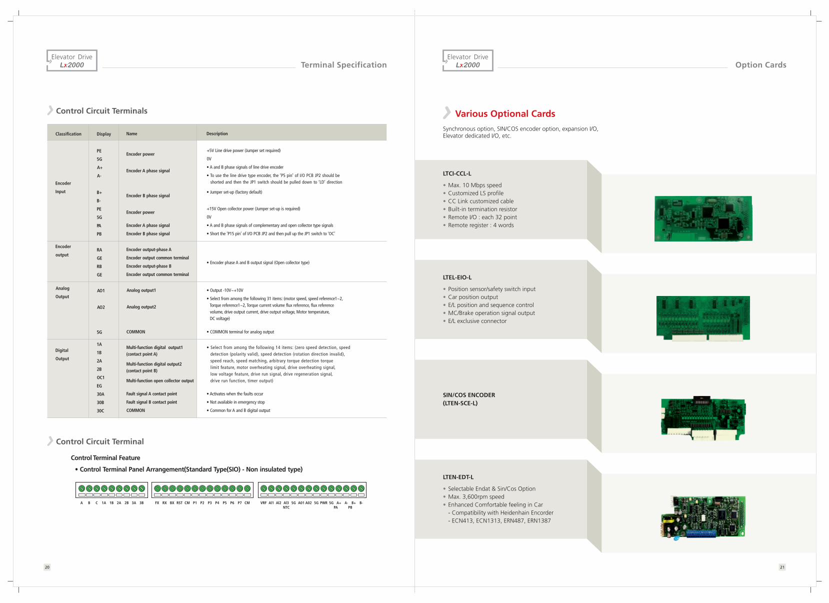
Option CardsTerminal Specification
Classification
Encoder
Input
Encoder
output
Analog
Output
Digital
Output
Display
PE
5G
A+
A-
B+
B-
PE
5G
PA
PB
RA
GE
RB
GE
AO1
AO2
5G
1A
1B
2A
2B
OC1
EG
30A
30B
30C
Name
Encoder power
Encoder A phase signal
Encoder B phase signal
Encoder power
Encoder A phase signal
Encoder B phase signal
Encoder output-phase A
Encoder output common terminal
Encoder output-phase B
Encoder output common terminal
Analog output1
Analog output2
COMMON
Multi-function digital output1(contact point A)
Multi-function digital output2(contact point B)
Multi-function open collector output
Fault signal A contact point
Fault signal B contact point
COMMON
Description
+5V Line drive power (Jumper set required)
0V
� A and B phase signals of line drive encoder
� To use the line drive type encoder, the �P5 pin� of I/O PCB JP2 should be shorted and then the JP1 switch should be pulled down to �LD� direction
� Jumper set-up (factory default)
+15V Open collector power (Jumper set-up is required)
0V
� A and B phase signals of complementary and open collector type signals
� Short the �P15 pin� of I/O PCB JP2 and then pull up the JP1 switch to �OC�
� Encoder phase A and B output signal (Open collector type)
� Output -10V~+10V
� Select from among the following 31 items: (motor speed, speed reference1~2, Torque reference1~2, Torque current volume flux reference, flux reference volume, drive output current, drive output voltage, Motor temperature, DC voltage)
� COMMON terminal for analog output
� Select from among the following 14 items: (zero speed detection, speed detection (polarity valid), speed detection (rotation direction invalid), speed reach, speed matching, arbitrary torque detection torque limit feature, motor overheating signal, drive overheating signal, low voltage feature, drive run signal, drive regeneration signal, drive run function, timer output)
� Activates when the faults occur
� Not available in emergency stop
� Common for A and B digital output
Control Circuit Terminals
Control Terminal Feature
� Control Terminal Panel Arrangement(Standard Type(SIO) - Non insulated type)
Control Circuit Terminal
A B C 1A 1B 2A 2B 3A 3B FX RX BX RST CM P1 P2 P4 P5 CMP6 P7P3 VRF Al1 Al2 Al3NTC
5G A01 A02 5G PWR 5G A+ A- B-B+PA PB
Elevator Drive Elevator Drive
2120
Various Optional Cards
Synchronous option, SIN/COS encoder option, expansion I/O,Elevator dedicated I/O, etc.
LTCI-CCL-L
� Max. 10 Mbps speed� Customized LS profile� CC Link customized cable� Built-in termination resistor� Remote I/O : each 32 point� Remote register : 4 words
LTEL-EIO-L
� Position sensor/safety switch input� Car position output� E/L position and sequence control� MC/Brake operation signal output� E/L exclusive connector
LTEN-EDT-L
� Selectable Endat & Sin/Cos Option� Max. 3,600rpm speed� Enhanced Comfortable feeling in Car - Compatibility with Heidenhain Encorder - ECN413, ECN1313, ERN487, ERN1387
SIN/COS ENCODER(LTEN-SCE-L)

Braking Unit and ResistorBraking Unit and ResistorElevator Drive Elevator Drive
Breaking Unit LED Functions
Description
Main power in braking unit turns on the POWER LED. Generally the braking unit is wired to the drive, soonce the input main power of drive is on, the POWER LED of braking unit turns on.
While braking unit operates its normal operation by the motor regenerative energy, the RUN LED blinks.
During the braking operation, if the braking unit heat sink is overheated and exceeds its limited value, the overheat protection function operates. This blocks the braking unit signal and then turns on the OHT LED.
During the braking operation, if over-current flows in the main circuit of braking unit then the over current protection function is operated in order to prevent the circuit from over current. The TURN ON signal of braking unit is blocked and then turns on the OCT LED.
Displayed Item
POWER
RUN
OHT
OCT
Brake resistor wiring
Brake resistor terminal blocks Drive terminals
P,BR
One of the multi-function input terminals,out of P1~P7, of control terminals board isused as defining �External trip signal contact B�
Operation
The contact is ON in normal temperature and opens in overheat.
For brake resistor with a temperature detection sensor for fire protection, refer below when in use.
B1, B2
P7, CM
Terminal Block and Braking Unit
Main circuit terminal block Control circuit terminal
IN+ IN- OUT+ OUT- 30B 30C 30A
G N B2 B1
Terminal Block and Braking Unit
Double use of Braking Unit
Combination of Braking Units and Braking Resistors
� 30~37kW (230V/415V) � 45kW (415V)
LTDBU-0370-2LTDBU-0370-4
3�-5kW/12�-5kW
제동유닛LTDBU-0750-4
12�-5kW
Drive Drive
Brakingunit
Brakingunit
12�-5kW
Braking resistor
Braking resistor
Braking resistor specifications
Resistance values in the table shown below are calculated based on the 150% braking torque, 10%ED* standard.
▶ * % ED is based on 100sec.
Drive Cat. No. [ Ω] Capacity (10%ED)
[W]
LTVF-L20012AAA
LTVF-L20016AAA
LTVF-L20024AAA
LTVF-L20032AAA
LTVF-L20046AAA
LTVF-L20059AAA
LTVF-L20074AAA
LTVF-L20088AAA
800
1200
1600
2400
4800
4800
7200
7200
Input Voltage
Three-Phase 230V
Three-Phase 415V
LTVF-L40006AAA
LTVF-L40008AAA
LTVF-L40012AAA
LTVF-L40016AAA
LTVF-L40024AAA
LTVF-L40030AAA
LTVF-L40039AAA
LTVF-L40045AAA
50
33
20
15
10
8
5
5
200
130
85
60
40
30
20
20
800
1200
1600
2400
4800
4800
7200
7200
2322

Dimensions & WeightsPeripheral Device
MCCB (Moulded Case Circuit Breaker) and MC (Magnetic Contactor)
Elevator Drive Elevator Drive
W (mm) H (mm) D (mm)
207
207
207
207
207
202
202
202
202
221
221
221
221
254
254
254
LTVF-L20012AAA
LTVF-L20016AAA
LTVF-L40006AAA
LTVF-L40008AAA
LTVF-L20024AAA
LTVF-L20032AAA
LTVF-L40012AAA
LTVF-L40016AAA
LTVF-L20046AAA
LTVF-L20059AAA
LTVF-L40024AAA
LTVF-L40030AAA
LTVF-L20074AAA
LTVF-L20088AAA
LTVF-L40039AAA
LTVF-L40045AAA
Weight (kg)
6
6
6
6
14
14
14
14
13.7
13.7
13.7
13.7
20.3
20.3
20.3
20.3
284
284
284
284
284
355
355
355
355
385
385
385
385
460
460
460
200
200
200
200
200
200
200
200
200
250
250
250
250
304
304
304
30 ~ 37kW (230V/415V)
MC (L&T)
MO 18
MO 32
MO 50
MO 50
MO 70
MO 95
MNX 140
MNX 140
MNX 140
MNX 225
MO 12
MO 18
Input Voltage Motor (kW) MCCB (L&T)Drive Cat. No.
230V
415V
2.2
3.7
5.5
7.5
11
15
18.5
22
30
37
2.2
3.7
5.5
7.5
11
15
18.5
22
30
37
45
LTVF-L20012AAA
LTVF-L20016AAA
LTVF-L20024AAA
LTVF-L20032AAA
LTVF-L20046AAA
LTVF-L20059AAA
LTVF-L20074AAA
LTVF-L20088AAA
LTVF-L20122AAA
LTVF-L20146AAA
LTVF-L40006AAA
LTVF-L40008AAA
LTVF-L40012AAA
LTVF-L40016AAA
LTVF-L40024AAA
LTVF-L40030AAA
LTVF-L40039AAA
LTVF-L40045AAA
LTVF-L40061AAA
LTVF-L40075AAA
LTVF-L40091AAA
DM100/30
DM100/30
DM100/50
DM100/60
DN2-250M/100
DN2-250M/125
DN2-250M/160
DN2-250M/160
DN2-250M/250
DN3-400M/320
DM16/16
DM16/16
DM100/30
DM100/30
DM100/50
DM100/60
DM100/80
DN2-250M/100
DN2-250M/125
DN2-250M/160
DN2-250M/160
MO 25
MO 32
MO 50
MO 50
MO 70
MO 70
MO 95
MNX 140
MNX 140
2.2 ~ 22kW (230V/415V)
Input V oltage
Three -Phase230V
Three -Phase415V
Drive Cat. No.
LTVF-L20122AAA
LTVF-L20146AAA
LTVF-L40061AAA
LTVF-L40075AAA
LTVF-L40091AAA
350
350
350
350
375
680
680
680
680
780
308.2
308.2
308.2
308.2
326
42
42
42
42
63
W (mm) H (mm) D (mm) Weight (kg)Input V oltage
Three -Phase230V
Three -Phase415V
Drive Cat. No.
2524
Three-Phase
Three-Phase