high performance double offset butterfly valve manual ... butterfly valves... · operating and...
TRANSCRIPT
Operating and installation manual Proven Quality since 1892
ECON high performance butterfly series 91 & 93 Page 1 of 19
www.eriks.com
Rev.0
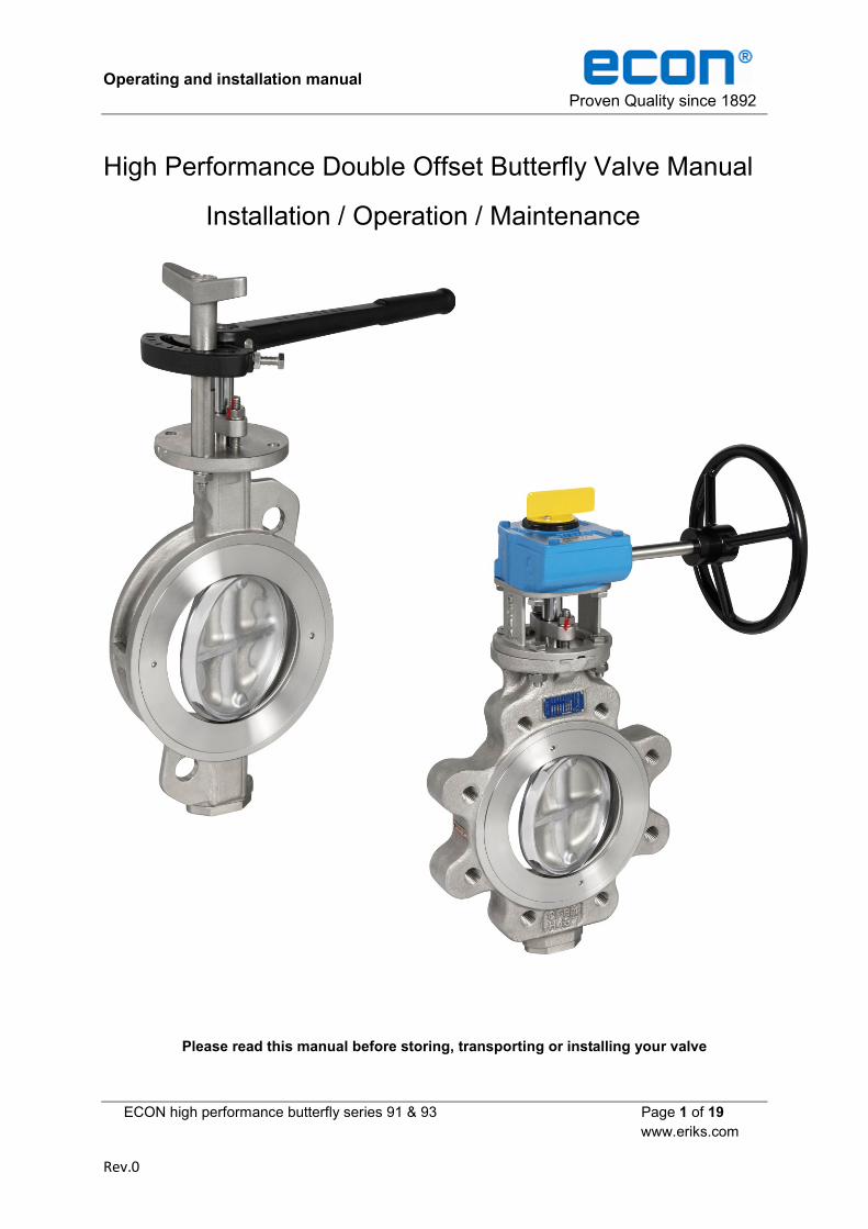
High Performance Double Offset Butterfly Valve Manual
Installation / Operation / Maintenance
Please read this manual before storing, transporting or installing your valve

Operating and installation manual Proven Quality since 1892
ECON high performance butterfly series 91 & 93 Page 2 of 19
www.eriks.com
Rev.0
Content
1. Introduction 2. ERIKS operating companies 3. Requirements for maintenance staff 4. Transport and storage 5. Precautions to be taken prior to installation 6. Installation 7. Maintenance 8. Assembly and Disassembly 9. Function test 10. Cleaning of piping 11. Removal 12. Disposal 13. Parts and Service 14. Troubleshooting guide 15. Application
Annex I 1. Introduction
In order to benefit from the excellent properties of the ECON high performance butterfly valves it is necessary to follow the instructions of this user manual carefully. For errors resulting from improper installation the manufacturer or distributer can’t be held responsible. Consult the applicable standards for allowable flange dimensions. Dimensions, materials and applicability of these valves should be derived from the technical ECON datasheets and documentation. ECON series 91 wafer type and 93 lug type are double eccentric high performance butterfly valves. The valve design is based on a double eccentric geometry of the disc rotating centre, utilizing a floating radius machined seal ring. This design makes the disc move back and away from the body seat during the opening movement. (Fig.1.1). The double eccentric design decreases the seat friction, which results in an extension of the valves life span and lower operating torques. If repair is needed the seat can be replaced easily without removing the valve shaft. Valves with PTFE, RPTFE or PTFE/Inconel seats can be used for media from -29°C up to 210°C. Valves with a fully Inconel seat can be used for temperatures from -29°C up to 500°C. These ECON valves are bi-directional, but do have a preferred flow direction. It’s however strongly recommended to install the valves in the preferred flow direction, as it will extend the valve’s life span and will also lower the operating torque. (Fig. 1.2)
Fig. 1.1

Operating and installation manual Proven Quality since 1892
ECON high performance butterfly series 91 & 93 Page 3 of 19
www.eriks.com
Rev.0
2. ERIKS operating companies ECON high performance butterfly valves are being supplied by several ERIKS operating companies worldwide. In this manual these will be referred to as ‘ERIKS’, the individual terms of delivery of the ERIKS operating company having executed the order are applicable.
3. Requirements for maintenance staff The staff assigned to assembly, operating and maintenance tasks should be qualified to carry out such jobs and in any circumstance, ensure personal safety.
4. Transport and storage
The valve must be transported and stored dry and clean. In humid rooms, a drying material or heating must be used to avoid condensation. During transport and intermediate storage the high performance butterfly valve should not be outside a temperature range of -15°C and +30°C. The valve is supplied and has to be stored with the disc in a slightly open position.
5. Precautions to be taken prior to installation
Please make sure that the valve intended for installation is suitable for the service conditions prevailing. The responsibility about the used fluids (corrosion resistance, pressure, temperature, etc.) lies by the user of the plant. Please consider that turbulences (i.e. created by piping bows) generate hydro dynamic forces increasing the operating torque of the valve. We recommend installing the valve minimum 5x DN behind pipe fittings. For safety, follow these cautions before installing, removing or dissembling your valve.
Check if and what kind of medium is in the pipeline.
Make sure that the system is depressurized.
Use protective clothing and equipment to avoid injury.
Keep hands and other body parts out of the valve.
Always ensure that the valve is in the fully closed position before installation, removal or disassembly.
Keep flange faces clean before installation in pipeline
Preferred flow direction Non-Preferred flow direction
Fig. 1.2

Operating and installation manual Proven Quality since 1892
ECON high performance butterfly series 91 & 93 Page 4 of 19
www.eriks.com
Rev.0
Before installation of the valve into the piping system, visually inspect the valve to determine if any
damage has occurred during shipping. Particularly, inspect the actuator, shaft, valve interior, valve
body and flanges. For proper operation of the valves, the seat and disc seal must be undamaged
and free of foreign material. If other than superficial damage is discovered, please contact your
supplier immediately, indicating the location and extent of the damage found.
If it is necessary to clean the valve, use a soft cloth and mineral spirits, or an equivalent solvent.
All rust preventives should be removed before installing your valve
There are no special tools required for installation and maintenance that are not commercially
available. Any lifting devices used to move the valve into a desired position shall be of sufficient
size to support the weight of the valve and actuator assembly. The nylon slings, secured around
the valve bearing areas, are recommended to reduce the possibility of mechanical damage
occurring to the valve body and actuator. (Fig. 2) The assembly should never be lifted by the
actuator. Lifting areas on the actuator are for removal and installation of the actuator to the valve
only.
WARNING
NEVER pass a lifting device through the valve port. Severe damage may occur.
6. Installation The valve must be installed so that pipeline stresses are not transmitted to the valve body. Despite its solid manufacture, such stress may affect valve operation. If pipeline stresses are severe, they should be cushioned by expansion joints or compensators. If supports are necessary to carry the weight of the valve, they should only support the dead weight of the valve and should not serve as base points for the pipeline.
Fig. 2

Operating and installation manual Proven Quality since 1892
ECON high performance butterfly series 91 & 93 Page 5 of 19
www.eriks.com
Rev.0
Steps of installation
All valves must be in fully closed position during installation or removal. It is not necessary to torque seat the valve, but the disc travel must be restricted to prevent damage.
Please make sure that the valve is clean and that there is no foreign material inside the valve and pipe.
The arrow on the valve body indicates the preferred flow direction. It also indicates the high pressure side of the valve, obtaining the best closure performance. During installation the best valve position must be determined in order to utilize this feature. This may not necessary be the common flow direction of the system Fig.3)
Please install the valve stem horizontally (Fig.4), in order to prevent damage to the stem
bearing of the valve by sediment that builds up around bottom of the pipe system.
Install the valve and gaskets into the pipeline (Fig.5).
Fig. 3
Fig. 4

Operating and installation manual Proven Quality since 1892
ECON high performance butterfly series 91 & 93 Page 6 of 19
www.eriks.com
Rev.0
Make sure the valve will be perfectly centred between the pipe flanges, in order to prevent
damaging the disc by interference with the pipe flange (Fig.6)
The correct installation of butterfly valves connected to an elbow would be to align the stem
position in order to have equal flow on each side of the shaft, minimizing dynamic torque on
the valve disc. (Fig.7)
Excellent Good No recommend
Always use an extension tube between a wafer check valve and butterfly valve. Do never
connect them directly. (Fig.8)
Fig. 5 Fig. 6
Fig. 7

Operating and installation manual Proven Quality since 1892
ECON high performance butterfly series 91 & 93 Page 7 of 19
www.eriks.com
Rev.0
Flange connecting & bolting
o Keep valve protection boards in place until the valve is being mounted in the pipe system.
o Make sure the material and size of gaskets are suitable for the service. Check if the flange faces are clean and undamaged.
o Check all bolts and nuts. They must be in undamaged condition. o Apply lubricant such as Molykote to all bolts and nuts before tightening them. o The pipe support(s) may now be required to be partially disengaged in order to make
enough clearance to mount the valve and the flange gaskets. o The opposite connecting pipe flange face may not be further away than a 1/4 inch
(6mm) from the valve flange face. If this distance is bigger, an alternate method, other than using the flange bolts, must be selected in order close the gap between the pipe flange and valve.
o Tighten four of the flange bolts equally divided over the flange by a quarter turn at a time, until the flange touches the flange face of the valve. During this operation, it is advisable to continually check the distance between the flange faces. Tighten the bolts to approximately 25% of the final torque value (see table 1).
o Inspect the remaining bolts and assure correct alignment. Tighten them to the same level as the first four bolts.
o Complete the tightening of all flange bolts in minimal four steps by increasing the torque by every step, until the final torque value (table 1) has been reached. Tighten the bolts crosswise according to fig. 9
o Test cycle the valve to be sure that the disc is not interfering with the pipe flange.
Fig. 8

Operating and installation manual Proven Quality since 1892
ECON high performance butterfly series 91 & 93 Page 8 of 19
www.eriks.com
Rev.0
Bolt tightening sequence
Actual torque shall depend on gasket type, consult your gasket supplier.
Removal procedure o To remove your valve from the pipeline, please follow these simple steps:
Ensure the valve is in the fully closed position. Ensure that the system is depressurized. Ensure the actuator is disconnected from the power or air supply. Use protective clothing and equipment to prevent injury. If your valve is equipped with a fail-open actuator, close the valve manually or
dismount the actuator from the valve and close the valve before removal from the pipe system.
Attach nylon slings to the body shoulders of the valve. Remove the flange bolts.
Caution o High performance valves are not suitable for media that contain solid particles, which
could damage the valve seat. o Make sure the valve materials are resistant to the medium. o Make sure that the valve is suitable for the medium, medium pressure and
temperature. o The medium temperature must be within a range of -29 ~ 210°C for PTFE seated
valves and within a range of -29 ~ 500°C for fully Inconel seated valves. o The maximum working pressure may not be higher than the design pressure of the
valve.
Installation o Check what kind of medium is in the pipeline. o Make sure that the system is depressurized. o Make sure the arrow on the valve body, which shows the preferred flow direction of
the valve, points into the direction flow direction. o Use protective clothing and equipment to avoid injury. Keep hands and other body
parts out of the valve.
Bolt size Torque
(ft-lb) (Nm)
5/8” (M16) 110 150
3/4” (M20) 200 270
7/8” (M22) 320 434
1” (M26) 480 650
1-1/8”(M28) 600 815
1-1/4”(M32) 840 1140
Fig. 9
Table 1

Operating and installation manual Proven Quality since 1892
ECON high performance butterfly series 91 & 93 Page 9 of 19
www.eriks.com
Rev.0
o ALWAYS ENSURE THAT THE VALVE IS IN THE FULLY CLOSED POSITION BEFORE INSTALLATION, REMOVAL OR DISASSEMBLY.
o Before installation of the valve into the pipe system visually inspect the valve to determine if any damage has occurred during shipping. Particularly, inspect the actuator, stem, valve interior, valve body and flanges. For proper operation of the valves, the seat and disc sealing surface must be undamaged. If other than superficial damage is discovered, contact your supplier immediately, indicating the location and extent of the damage found.
o All seats and seals must be free of damage, please change a new one if damaged. o After installing the valve in the pipeline, check the flange connections for leakage by
using compressed air and soapy water. (Fig.10) o Make sure that the flange and valve faces and gaskets are clean and undamaged
before installation.
On service o Do not touch the valve body when it is in service. o Do not loosen flange bolts, valve bolts when valve is in service. (Fig.11) o The valve must be supported if pipeline vibration occurs, so that pipeline stresses are
not transmitted to the valve and actuator. o Don’t use an “F” wrench to operate the hand wheel or gear box. (Fig.12)
If there are problems which could not be eliminated during service, please contact your supplier and describe the valve and operation condition. (Fig.13)
X
X
Fig. 10 Fig. 11
Fig. 12 Fig. 13

Operating and installation manual Proven Quality since 1892
ECON high performance butterfly series 91 & 93 Page 10 of 19
www.eriks.com
Rev.0
7. Maintenance Please notice that fluid residues inside the butterfly valve could be dangerous for humans and the environment. The butterfly valve must be handled accordingly and be cleaned carefully prior to maintenance. Maintenance is made at the own risk of the user. Only original spare parts are to be used.
LUBRICATION SCHEDULE o We recommend your valve be inspected at least every three months to determine
lubrication and other maintenance requirements under your specific service conditions.
GLAND PACKING MAINTENANCE PROCEDURE o Routine maintenance of the gland packing consists of tightening the packing gland
periodically. If leakage around the gland packing is discovered, first tighten the hex-nuts on the gland follower (more than 2/3 compression) as this may reduce packing life. If the leakage still persists, replace the packing according to the following procedure. (For clarity, the actuator and bracket are not shown in the following diagrams. It is not necessary to remove the actuator or bracket before performing this procedure).
In order to gain access to the packing, remove the gland follower and slide it up to the actuator. See Fig. 14 hereunder:
Remove the complete packing from the gland packing using a flexible screw
hook (Fig. 15). For gland packing that contain a lantern ring, use a puller with
10-32 threads to remove the lantern ring. Save the lantern ring for reuse, but
discard the other packing material. Please replace the complete gland
packing. It can either be made of graphite or PTFE. (Fig.16)
Fig. 14

Operating and installation manual Proven Quality since 1892
ECON high performance butterfly series 91 & 93 Page 11 of 19
www.eriks.com
Rev.0
Inspect the stem, bore of the gland packing and the gland follower. These surfaces should be relatively scratching free (Fig.17.1). If there is any damage, polish the surface to 32 rms finish. If any part has severe damage, contact your supplier.
Install each new packing ring by using the gland follower to push each packing ring evenly into position. Stagger the splice-joints of each packing ring so they are as far as possible away from each other (see example above). Usually, rotating each ring until the splice is at 90° from the previous splice is sufficient. (Fig.17.2)
Fig. 15 Fig. 16
Fig. 17.1
Fig. 17.2

Operating and installation manual Proven Quality since 1892
ECON high performance butterfly series 91 & 93 Page 12 of 19
www.eriks.com
Rev.0
For V type PTFE packings, please follow this procedure, o For standard applications use configuration as shown in Fig.18. o For vacuum applications use configuration as shown in Fig.19.
Install the gland follower and tighten it firmly. DO NOT compress the gland
follower too much. Over-tightening may dramatically reduce the life of the packing and may increase the operating torque. The maximum torque of the gland nuts is mentioned in table 2.
Maintenance o Maintenance technicians must be trained before doing any valve repair. o Do not replace any gasket or seal if the pipeline is pressurized. o Repainting the valve when it starts to corrode. o If internal valve parts start to corrode, please check the resistance of this part to the
medium and replace the part by a genuine part that is resistant. o If the valve body is corroded heavily, please measure the thickness and check Annex I
if it still can be used safely. o Please check abrasion or wear of the stem, disc and seats and verify if they still can
ensure a proper operation of the valve.
Graphite Packing PTFE “V” Type Packing
Screw Size Max. Torque Screw Size Max. Torque
M8 11 Nm M8 11 Nm
M10 12 Nm M10 12 Nm
M12 14 Nm M12 14 Nm
M16 45 Nm M16 22 Nm
M20 65 Nm M20 27 Nm
Fig. 18 Fig. 19
Table 2
Operating and installation manual Proven Quality since 1892
ECON high performance butterfly series 91 & 93 Page 13 of 19
www.eriks.com
Rev.0
o Always check what kind of medium is in the pipe system. It might be dangerous for your health or the environment.
o Ensure that the pipe system is depressurized and that the medium temperature has reached a safe level.
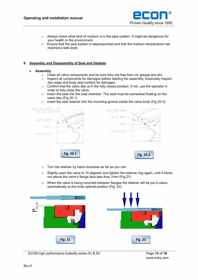
8. Assembly and Disassembly of Seat and Gaskets
Assembly o Clean all valve components and be sure they are free from oil, grease and dirt. o Inspect all components for damages before starting the assembly. Especially inspect
disc edge and body seat surface for damages. o Confirm that the valve disc is in the fully closed position. If not, use the operator in
order to fully close the valve. o Insert the seat into the seat chamber. The seat must be somewhat floating on the
valve disc (Fig.20.1) o Insert the seat retainer into the mounting groove inside the valve body (Fig 20.2).
o Turn the retainer by hand clockwise as far as you can
o Slightly open the valve to 10 degrees and tighten the retainer ring again, until it sticks out above the valve’s flange face less than 1mm (Fig.21).
o When the valve is being mounted between flanges the retainer will be put in place automatically to the most optimal position (Fig. 22).
Fig. 20.1
Fig. 21 Fig. 22
Fig. 20.2

Operating and installation manual Proven Quality since 1892
ECON high performance butterfly series 91 & 93 Page 14 of 19
www.eriks.com
Rev.0
o Operate the actuator again to bring the disc to the fully closed position before mounting to the pipe system.
o Insert the studs into the threaded holes in the top-flange of the valve. o Install the packing follower and tighten it with the hex nuts. Tighten both hex nuts
equally. o Install the bottom cover with a gasket and tighten it with the hex-socket cap screws. o The valve is now ready for actuator mounting. Please check the disc position before
mounting the actuator and consult the actuator instruction and operation manual for further details.
Disassembly o Place the valve on a working bench or other suitable working surface with the drive
shaft side of the valve up. Remove the actuator and actuator bracket from the valve. (Fig.23)
o Separate the packing follower by removing the hex-nuts from the studs, and then remove the studs.
o Remove the gland packing using a flexible screw-hook. o Remove the packing retainer and be careful not to damage the finish of the packing
chamber and/or stem. o Open the disc up to 90° and separate the seat retainer (Fig.24), seat (Fig.25), from the
valve body.
Fig. 23
Fig. 24 Fig. 25

Operating and installation manual Proven Quality since 1892
ECON high performance butterfly series 91 & 93 Page 15 of 19
www.eriks.com
Rev.0
9. Function test Before the system is put into operation, it’s recommended to do a function test. Therefore the valve must be opened and closed at least once in order to check that the disc doesn’t touch the flanges and that the valve does close completely. If a pressure test of the complete piping system is being carried out, it is very important that the testing pressure is not higher than the nominal pressure of the valve. An overpressure may damage the valve.
10. Cleaning of the piping
When cleaning the piping system it is very important to assure that the cleaning products and devices are harmless for the valve. Not appropriate products and devices might damage the valve.
11. Removal Before removing the valve from the pipe, consider that dangerous fluids might leak. Corresponding measures of precaution have to be applied.
12. Disposal Please notice that some residues could remain in the inner of the valve and that they might be dangerous for people or the environment. Therefore, the butterfly valve has to be handled with the corresponding caution. After its use, the butterfly valve has to be disposed of according to the state of the art and taking into account the environment.
13. Parts and service
Fig. 26

Operating and installation manual Proven Quality since 1892
ECON high performance butterfly series 91 & 93 Page 16 of 19
www.eriks.com
Rev.0
14. Troubleshooting guide
You may try the following procedures before contacting your supplier. If your valve doesn’t operate properly before or after trying these trouble- shooting ideas, you may contact your supplier for assistance.
LEAKAGE FROM GLAND PACKING If leakage around the gland packing is discovered, first tighten the nuts on the gland follower to stop the leakage. Do not over tighten the gland follower (more than 2/3 compression) as this may reduce packing life. If the leakage still persists, replace the packing according to the procedure in the “Gland Packing Maintenance Procedure” section.
LEAKAGE BETWEEN SEAL AND DISC Inspect disc edge and seat for damage or excessive wear. If necessary, the disc edge may be lightly hand polished using wet 400grit sandpaper. If leakage persists, the seat and/or disc must be replaced. Re-check for leakage. If leakage still persists, contact your supplier for repair.
SPARE PARTS
SERIES 91 and 93
No. Name Materials Quantity
19 SEAT
PTFE 1
PTFE+15%GLASS 1
PTFE+15%GRAPHITE 1
INCONEL 718 1
ASTM A240 Gr.316 1
3 FIRE SAFE (second) SEAT (only in
combination with PTFE or RPTFE seat) INCONEL 718 1
7 GLAND PACKING
PTFE 1
PTFE+15%GRAPHITE 1
GRAPHITE 1
12 BOTTOM COVER SEAL
GRAPHITE 1
PTFE 1
18 SEAT GASKET FOR METAL SEATS
AND FIRE SAFE SEATS GRAPHITE 1

Operating and installation manual Proven Quality since 1892
ECON high performance butterfly series 91 & 93 Page 17 of 19
www.eriks.com
Rev.0
Fig. 27
Fig. 9130 with
PTFE/Inconel fire
safe seat
Operating and installation manual Proven Quality since 1892
ECON high performance butterfly series 91 & 93 Page 18 of 19
www.eriks.com
Rev.0
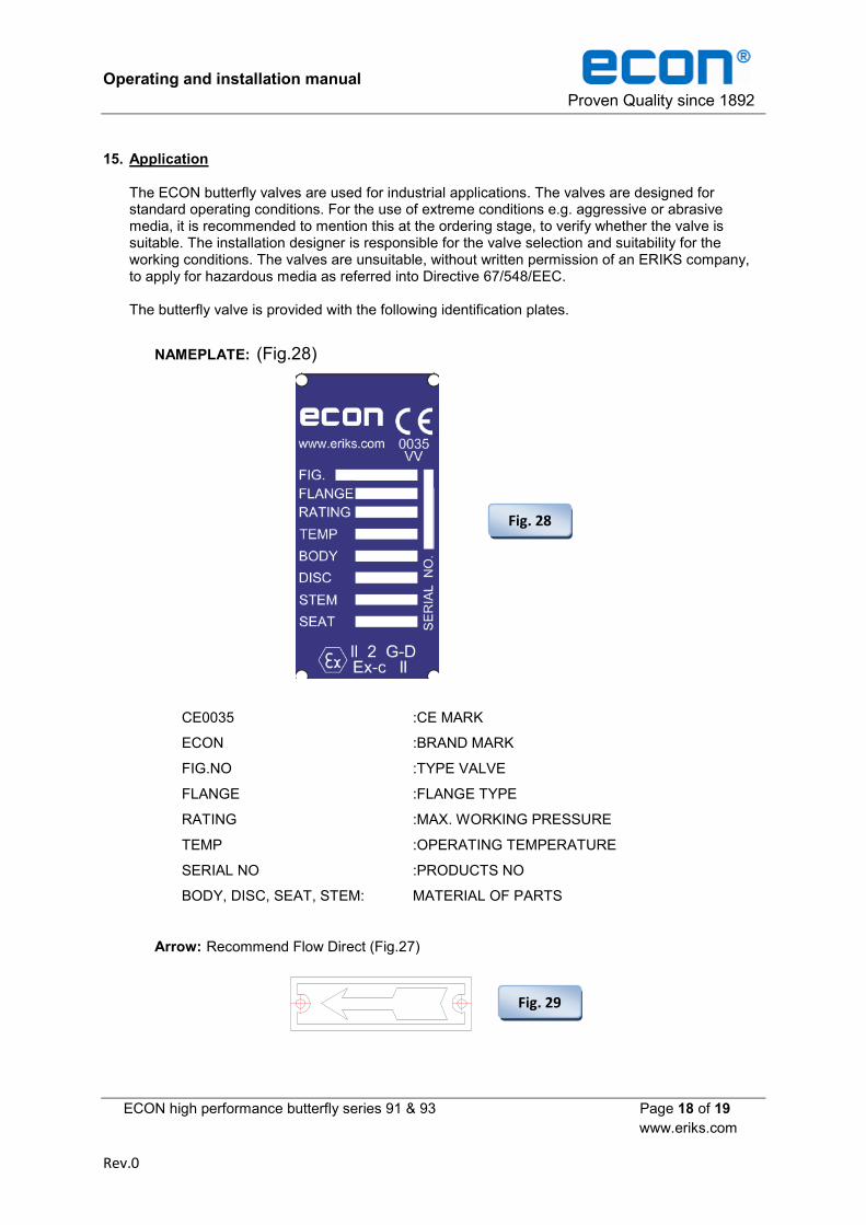
15. Application The ECON butterfly valves are used for industrial applications. The valves are designed for standard operating conditions. For the use of extreme conditions e.g. aggressive or abrasive media, it is recommended to mention this at the ordering stage, to verify whether the valve is suitable. The installation designer is responsible for the valve selection and suitability for the working conditions. The valves are unsuitable, without written permission of an ERIKS company, to apply for hazardous media as referred into Directive 67/548/EEC. The butterfly valve is provided with the following identification plates.
NAMEPLATE: (Fig.28)
CE0035 :CE MARK
ECON :BRAND MARK
FIG.NO :TYPE VALVE
FLANGE :FLANGE TYPE
RATING :MAX. WORKING PRESSURE
TEMP :OPERATING TEMPERATURE
SERIAL NO :PRODUCTS NO
BODY, DISC, SEAT, STEM: MATERIAL OF PARTS
Arrow: Recommend Flow Direct (Fig.27)
Fig. 28
Fig. 29

Operating and installation manual Proven Quality since 1892
ECON high performance butterfly series 91 & 93 Page 19 of 19
www.eriks.com
Rev.0
ECON Brand mark (Fig.30)
Annex I
Check list for minimum wall thickness (ASME B 16.34)
Minimum thickness (mm) for each pressure rating
Size (in) Items Class 150 Class 300 Size (in) Items Class 150 Class 300
2 t min 5.588 6.350 24 t min 14.732 24.638
2.5 t min 5.588 6.350 26 t min 15.494 26.416
3 t min 5.588 7.112 28 t min 16.256 27.940
4 t min 6.350 9.652 30 t min 17.018 29.718
5 t min 7.112 8.636 32 t min 18.034 31.242
6 t min 7.112 9.652 34 t min 18.796 33.020
8 t min 7.875 11.176 36 t min 19.558 34.798
10 t min 8.636 12.700 40 t min 21.336 38.100
12 t min 9.652 14.224 42 t min 22.098 39.624
14 t min 10.668 16.510 44 t min 22.860 41.402
16 t min 11.430 18.034 46 t min 23.622 43.180
18 t min 12.192 19.812 48 t min 24.638 44.704
20 t min 12.954 21.336 50 t min 25.400 46.482
The minimum wall thickness was designed according to ASME B16.34-1988
Fig. 30