high-performance service-oriented computing a...
TRANSCRIPT

HIGH-PERFORMANCE SERVICE-ORIENTED COMPUTING
A DISSERTATION
SUBMITTED TO THE DEPARTMENT OF ELECTRICAL
ENGINEERING
AND THE COMMITTEE ON GRADUATE STUDIES
OF STANFORD UNIVERSITY
IN PARTIAL FULFILLMENT OF THE REQUIREMENTS
FOR THE DEGREE OF
DOCTOR OF PHILOSOPHY
Nicholas McDonald
June 2016

http://creativecommons.org/licenses/by/3.0/us/
This dissertation is online at: http://purl.stanford.edu/gb403yz8060
© 2016 by Nicholas George McDonald. All Rights Reserved.
Re-distributed by Stanford University under license with the author.
This work is licensed under a Creative Commons Attribution-3.0 United States License.
ii

I certify that I have read this dissertation and that, in my opinion, it is fully adequatein scope and quality as a dissertation for the degree of Doctor of Philosophy.
Bill Dally, Primary Adviser
I certify that I have read this dissertation and that, in my opinion, it is fully adequatein scope and quality as a dissertation for the degree of Doctor of Philosophy.
John Ousterhout
I certify that I have read this dissertation and that, in my opinion, it is fully adequatein scope and quality as a dissertation for the degree of Doctor of Philosophy.
Al Davis
Approved for the Stanford University Committee on Graduate Studies.
Patricia J. Gumport, Vice Provost for Graduate Education
This signature page was generated electronically upon submission of this dissertation in electronic format. An original signed hard copy of the signature page is on file inUniversity Archives.
iii

Abstract
This dissertation presents Sikker, a highly-scalable high-performance distributed system ar-
chitecture for secure service-oriented computing. Sikker includes a novel service-oriented
application model upon which security and isolation policies are derived and enforced. The
workhorse of Sikker is a custom network interface controller, called the Network Manage-
ment Unit (NMU), that enforces Sikker’s security and isolation policies while providing
high-performance network access.
Sikker’s application model satisfies the complex interactions of modern large-scale dis-
tributed applications. Experimental results show that even when implemented on very large
clusters, the NMU adds a negligible message latency of 41 ns under realistic workloads and
91 ns at the 99.99th percentile of worst-case access patterns. Analysis shows that the NMU
can support many hundreds of Gbps of bandwidth with common VLSI technologies while
imposing zero overhead on the CPU.
Integrated into Sikker and the NMU is a novel service-oriented, distributed rate-control
algorithm, called Sender-Enforced Token and Rate Exchange (SE-TRE), that is able to
regulate service-to-service aggregate rates while imposing zero latency overhead at the
99.99th percentile, less than 0.3% bandwidth overhead, and zero overhead on the CPU.
Sikker’s service-oriented security and isolation methodology removes high overheads
imposed by current systems. Sikker allows distributed applications to operate in an en-
vironment with fine-grained security and isolation while experiencing supercomputer-like
network performance.
iv

Acknowledgements
I would like to specially thank two advisors in my academic career that have had enormous
impact on my success. My bachelor’s and master’s advisor, Professor Al Davis, provided
me with much inspiration and numerous opportunities. Without his positive encourage-
ment I would have settled on a less exciting and unrewarding career path that would have
not taken me to Stanford to pursue a PhD. My doctoral advisor, Professor William Dally,
taught me the art of academic research and impressed on me the desire to approach fun-
damental limitations to technology. Throughout my time at Stanford I benefited from his
numerous insights and his ability to instantaneously filter out my bad ideas. Professors
Christos Kozyrakis, Mendel Rosenblum, and John Ousterhout have all guided my research
in significant ways and helped guide me towards my goals. I would like to thank all the
members of the CVA research group for being great friends and colleagues.
I would like thank my mother, Tricia McDonald, for her endless support of me and
tirelessly putting up with me for many decades. She continuously showed patience and
understanding for my childhood desire to destruct all the electronic devices in our home
with many failed attempts to piece them back together. The amount of sacrifice my mother
has made for me is endless.
Last but certainly not least, I would like to thank my amazing wife, Kara McDonald,
who has supported me through thick and thin. Kara has been my driving force of confi-
dence even when I myself did not believe I could achieve my objectives. In addition to her
continuous love and patience, Kara brought our two beautiful daughters into this world.
She is an extraordinary wife, mother, and friend. I could not and would not have done this
without her. Just as my friend Song Han once pointed out, “I am a happy man!”
v

Contents
Abstract iv
Acknowledgements v
1 Introduction 11.1 Service-Oriented Computing . . . . . . . . . . . . . . . . . . . . . . . . . 2
1.2 High-Performance Interconnects . . . . . . . . . . . . . . . . . . . . . . . 7
1.3 Contributions . . . . . . . . . . . . . . . . . . . . . . . . . . . . . . . . . 8
1.4 Dissertation Outline . . . . . . . . . . . . . . . . . . . . . . . . . . . . . . 8
2 Related Work 102.1 Supercomputing . . . . . . . . . . . . . . . . . . . . . . . . . . . . . . . . 10
2.2 Cloud Computing . . . . . . . . . . . . . . . . . . . . . . . . . . . . . . . 11
3 Motivation 143.1 Access Control . . . . . . . . . . . . . . . . . . . . . . . . . . . . . . . . 14
3.2 Rate Control . . . . . . . . . . . . . . . . . . . . . . . . . . . . . . . . . . 18
4 Sikker 224.1 Application Model . . . . . . . . . . . . . . . . . . . . . . . . . . . . . . 22
4.2 Addressing and Authentication . . . . . . . . . . . . . . . . . . . . . . . . 25
4.3 Fixed Permissions . . . . . . . . . . . . . . . . . . . . . . . . . . . . . . . 26
4.4 One Time Permissions . . . . . . . . . . . . . . . . . . . . . . . . . . . . 29
4.5 Rate Control . . . . . . . . . . . . . . . . . . . . . . . . . . . . . . . . . . 31
vi
4.6 Network Operating System . . . . . . . . . . . . . . . . . . . . . . . . . . 32
4.7 Connectivity Model . . . . . . . . . . . . . . . . . . . . . . . . . . . . . . 34
4.8 Scalability . . . . . . . . . . . . . . . . . . . . . . . . . . . . . . . . . . . 35
4.9 Summary . . . . . . . . . . . . . . . . . . . . . . . . . . . . . . . . . . . 37
5 Rate Control Algorithms 395.1 Nothing Enforced (NE) . . . . . . . . . . . . . . . . . . . . . . . . . . . . 40
5.2 Relay Enforced (RE) . . . . . . . . . . . . . . . . . . . . . . . . . . . . . 40
5.3 Sender-Enforced - Fixed Allocation (SE-FA) . . . . . . . . . . . . . . . . . 43
5.4 Sender-Enforced - Token Exchange (SE-TE) . . . . . . . . . . . . . . . . . 44
5.5 Sender-Enforced - Rate Exchange (SE-RE) . . . . . . . . . . . . . . . . . 46
5.6 Sender-Enforced - Token and Rate Exchange (SE-TRE) . . . . . . . . . . . 47
6 Network Management Unit 496.1 Architecture . . . . . . . . . . . . . . . . . . . . . . . . . . . . . . . . . . 49
6.1.1 Authenticated OS-Bypass . . . . . . . . . . . . . . . . . . . . . . 50
6.1.2 Nested Hash Map Accelerator . . . . . . . . . . . . . . . . . . . . 53
6.1.3 Permissions Enforcement . . . . . . . . . . . . . . . . . . . . . . . 54
6.1.4 Management . . . . . . . . . . . . . . . . . . . . . . . . . . . . . 54
6.2 Operation . . . . . . . . . . . . . . . . . . . . . . . . . . . . . . . . . . . 55
6.2.1 Send . . . . . . . . . . . . . . . . . . . . . . . . . . . . . . . . . 55
6.2.2 Receive . . . . . . . . . . . . . . . . . . . . . . . . . . . . . . . . 56
6.2.3 Send with OTP . . . . . . . . . . . . . . . . . . . . . . . . . . . . 56
6.2.4 Receive with OTP . . . . . . . . . . . . . . . . . . . . . . . . . . 56
6.2.5 Send using OTP . . . . . . . . . . . . . . . . . . . . . . . . . . . 57
6.2.6 Rate Control . . . . . . . . . . . . . . . . . . . . . . . . . . . . . 57
7 Access Control Evaluation 587.1 Methodology . . . . . . . . . . . . . . . . . . . . . . . . . . . . . . . . . 58
7.1.1 Simulation . . . . . . . . . . . . . . . . . . . . . . . . . . . . . . 58
7.1.2 Permission Access Patterns . . . . . . . . . . . . . . . . . . . . . . 59
7.2 Results . . . . . . . . . . . . . . . . . . . . . . . . . . . . . . . . . . . . . 61
vii

7.2.1 Latency . . . . . . . . . . . . . . . . . . . . . . . . . . . . . . . . 61
7.2.2 Bandwidth . . . . . . . . . . . . . . . . . . . . . . . . . . . . . . 63
7.2.3 Security . . . . . . . . . . . . . . . . . . . . . . . . . . . . . . . . 64
7.3 Summary . . . . . . . . . . . . . . . . . . . . . . . . . . . . . . . . . . . 66
8 Rate Control Evaluation 678.1 Methodology . . . . . . . . . . . . . . . . . . . . . . . . . . . . . . . . . 67
8.2 Results . . . . . . . . . . . . . . . . . . . . . . . . . . . . . . . . . . . . . 70
8.3 Discussion . . . . . . . . . . . . . . . . . . . . . . . . . . . . . . . . . . . 75
8.3.1 Token Bucket Sizing . . . . . . . . . . . . . . . . . . . . . . . . . 75
8.3.2 Greed and Generosity . . . . . . . . . . . . . . . . . . . . . . . . 77
8.4 Summary . . . . . . . . . . . . . . . . . . . . . . . . . . . . . . . . . . . 78
9 Optimizations and Improvements 799.1 Contiguous Process Placement . . . . . . . . . . . . . . . . . . . . . . . . 79
9.2 End-to-End Zero Copy . . . . . . . . . . . . . . . . . . . . . . . . . . . . 81
9.2.1 Send Templates . . . . . . . . . . . . . . . . . . . . . . . . . . . . 82
9.2.2 Receive Templates . . . . . . . . . . . . . . . . . . . . . . . . . . 83
9.3 Buffered Demux . . . . . . . . . . . . . . . . . . . . . . . . . . . . . . . 86
9.4 NMU Placement . . . . . . . . . . . . . . . . . . . . . . . . . . . . . . . 89
10 Conclusion 90
Bibliography 92
viii

List of Tables
3.1 A network-oriented ACL (NACL) entry. . . . . . . . . . . . . . . . . . . . 15
3.2 A service-oriented ACL (SACL) entry. . . . . . . . . . . . . . . . . . . . . 16
4.1 Connectivity parameters for the service interaction model. . . . . . . . . . 34
5.1 Rate-control variables . . . . . . . . . . . . . . . . . . . . . . . . . . . . . 41
7.1 Throughput performance of a single NMU logic engine . . . . . . . . . . . 63
8.1 Rate-control evaluation results of the six algorithms. . . . . . . . . . . . . 75
8.2 SE-TRE performance when varying the token bucket size. . . . . . . . . . 76
9.1 Compressed service encoding with contiguity . . . . . . . . . . . . . . . . 80
ix

List of Figures
1.1 High-level service-oriented connectivity . . . . . . . . . . . . . . . . . . . 3
1.2 Twitter’s Finagle RPC system [1]. . . . . . . . . . . . . . . . . . . . . . . 5
1.3 Netflix’s architecture on AWS [2]. . . . . . . . . . . . . . . . . . . . . . . 5
1.4 Hailo’s service interactions [3]. . . . . . . . . . . . . . . . . . . . . . . . . 6
2.1 Network-related CPU overhead in cloud computing [4]. . . . . . . . . . . . 12
3.1 High-level service-oriented rate limits . . . . . . . . . . . . . . . . . . . . 18
3.2 Two services each with three processes . . . . . . . . . . . . . . . . . . . . 21
4.1 Services are composed of processes and domains . . . . . . . . . . . . . . 23
4.2 A system with 5 client services and a key-value store. . . . . . . . . . . . . 24
4.3 A Sikker system performing sender-enforced access control. . . . . . . . . 27
4.4 An example service interaction graph . . . . . . . . . . . . . . . . . . . . 28
4.5 The 4 stages of generating, sending, receiving, and using an OTP. . . . . . . 30
4.6 Example of assigning unidirectional service-level rate limits. . . . . . . . . 32
4.7 Scalability comparison between NACLs and SACLs . . . . . . . . . . . . . 37
5.1 A token bucket with size Sb being filled at rate Rt . . . . . . . . . . . . . . . 40
5.2 NE rate-control algorithm . . . . . . . . . . . . . . . . . . . . . . . . . . . 41
5.3 RE rate-control algorithm . . . . . . . . . . . . . . . . . . . . . . . . . . . 42
5.4 SE-FA rate-control algorithm . . . . . . . . . . . . . . . . . . . . . . . . . 43
5.5 SE-TE rate-control algorithm . . . . . . . . . . . . . . . . . . . . . . . . . 44
5.6 SE-RE rate-control algorithm . . . . . . . . . . . . . . . . . . . . . . . . . 46
5.7 SE-TRE rate-control algorithm . . . . . . . . . . . . . . . . . . . . . . . . 48
x

6.1 Hosts connect processes to the network via NMUs. . . . . . . . . . . . . . 50
6.2 The NMU architectural diagram. . . . . . . . . . . . . . . . . . . . . . . . 51
6.3 The interaction between 4 processes, the MMU, and the NMU . . . . . . . 52
6.4 The NMU’s internal nested hash maps data structures. . . . . . . . . . . . . 53
7.1 Mean, 99th%, and 99.99th% latency across four access patterns . . . . . . . 62
7.2 An NMU connected to an exploited host . . . . . . . . . . . . . . . . . . . 65
8.1 Stress testing traffic pattern for rate-control simulation. . . . . . . . . . . . 69
8.2 Bandwidth usage of the six rate-control algorithms . . . . . . . . . . . . . 71
8.3 End-to-end latency of the six rate-control algorithms. . . . . . . . . . . . . 72
8.4 Worst-case latency percentiles of the six rate-control algorithms. . . . . . . 73
8.5 Bandwidth overhead of the six rate-control algorithms. . . . . . . . . . . . 74
8.6 Results for SE-TRE with different token bucket sizes . . . . . . . . . . . . 76
9.1 Send templates. . . . . . . . . . . . . . . . . . . . . . . . . . . . . . . . . 84
9.2 Data structures used during a message receive with templates. . . . . . . . 85
9.3 Three different schemes of network message buffering. . . . . . . . . . . . 88
xi

Chapter 1
Introduction
The number and variety of applications and services running in data centers, cloud com-
puting facilities, and supercomputers has driven the need for a secure computing platform
with an intricate network isolation and security policy. Traditionally, supercomputers fo-
cused on performance at the expense of internal network security while data centers and
cloud computing facilities focused on cost efficiency, flexibility, and TCP/IP compatibility
all at the expense of performance. In spite of their historical differences, the requirements
of these computing domains are beginning to converge. With increased application com-
plexity, data centers and cloud computing facilities require higher network bandwidth and
predictably low latency. As supercomputers become more cost sensitive and are simul-
taneously utilized by many clients, they require a higher level of application isolation and
security. The advent of cloud based supercomputing [5, 6] brings these domains even closer
by merging them onto the same network.
Operating within a single administrative domain allows distributed systems to consider
the network a trusted entity and safely rely on the features it provides. Supercomputers use
this ideology to achieve ultimate performance, however, they maintain minimal security
and isolation mechanisms to achieve their performance goals. In contrast, cloud computing
facilities achieve high levels of security and isolation at the expense of much lower perfor-
mance. In theory, a single administrative domain can provide simultaneous performance,
security, and isolation as these are not fundamentally in opposition. The unfortunate truth
is that modern network technologies have not provided distributed systems that are capable
1

CHAPTER 1. INTRODUCTION 2
of supercomputer like network performance while simultaneously providing robust appli-
cation security and isolation. As a result, system designers and application developers are
forced into making trade offs between performance and security. This leaves deficiencies in
the system which makes application development harder and yields performance limiting
overheads.
This dissertation presents a new distributed system architecture called Sikker, that in-
cludes an explicit security and isolation policy. The goal of this system is to provide the
highest level of network performance while enforcing the highest level of application secu-
rity and isolation required by the complex interactions of modern large scale applications.
Sikker formally defines a distributed application as a collection of distributed services with
well defined interaction policies. Sikker utilizes specially architected network interface
controllers (NICs), called Network Management Units (NMUs), to enforce application se-
curity and isolation policies while providing efficient network access.
1.1 Service-Oriented Computing
The size of modern distributed applications spans from a few processes to potentially
millions of processes. Specifically, web based applications have ubiquitously adopted a
service-oriented architecture (SOA) in which the many processes of an application are
grouped by similarity into collections called services. A service is a collection of processes
developed and executed for the purpose of implementing a subset of an application’s func-
tionality. Applications can be comprised of one or more services, often tens or hundreds,
and services are often shared between many applications.
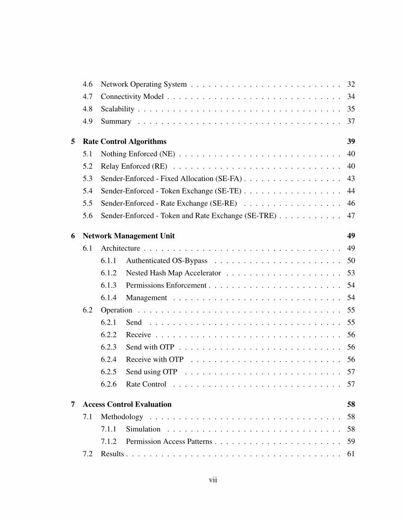
Figure 1.1 shows a simplified diagram of six services interacting to fulfill the func-
tionality of a user facing blogging application with viewing and editing capabilities. Each
service has a defined application programming interface (API) that it exposes to provide
functionality to other services. Even though a modern data center might contain thousands
of services, each service generally communicates with a small subset of the total services
in order to fulfill its designed functionality. Furthermore, it is common for a service to use
only a portion of another service’s API.
The Organization for the Advancement of Structured Information Standards (OASIS)
CHAPTER 1. INTRODUCTION 3
View MemCache
ADs UserDB
PostDBEdit
Figure 1.1: High-level service-oriented connectivity
[7], a nonprofit consortium that drives the development, convergence, and adoption of open
standards, has published a formal definition for a “Service-Oriented Architecture” as fol-
lows [8]:
Service-Oriented Architecture is a paradigm for organizing and utilizing dis-
tributed capabilities that may be under the control of different ownership do-
mains. It provides a uniform means to offer, discover, interact with and use
capabilities to produce desired effects consistent with measurable precondi-
tions and expectations.
The ubiquity of SOAs is evidence of their numerous advantages relative to other dis-
tributed programming paradigms. By nature of the architecture, core logic elements of an
application are separated and are managed separately both during development and oper-
ation. SOAs enable easy integration of services developed by third parties because each
service can be viewed as a black box and is often distributed along with client libraries
that developers can integrate into their own code base. These libraries enable a high level

CHAPTER 1. INTRODUCTION 4
of abstraction, support system specific optimization, and provide a means to support many
intercommunicating programming languages. Although not required by definition, SOAs
often make use of client-server protocols which are widely known to reduce the complexity
of distributed systems [9]. These protocols are structured as request-response interactions
and can be implemented synchronously or asynchronously.
In contrast to SOAs, the distributed shared memory (DSM) [10] paradigm keeps a co-
herent model of the memory address space across all machines. While this approach can
provide high performance data access on small systems, the additional complexity (i.e.,
distributed memory coherence) implemented by the system severely limits system scala-
bility. Paradigms such as partitioned global address space (PGAS), relax the coherency
constraint of DSM to exploit locality and increase system scalability. When faults occur in
shared memory paradigms like DSM and PGAS, they often break the entire system either
at the hardware level or application level. For this reason, many scientific computing work-
loads use check-pointing where they revert to known good states upon detection of faults.
In contrast, SOAs attempt to isolate faults within a service. In this regime, services are
responsible for handling faults within themselves and provide a durable interface to their
clients. Instead of creating complex systems with higher cost and lower fault frequency,
modern data centers using SOAs expect frequent faults and have built their systems to
handle these faults gracefully.
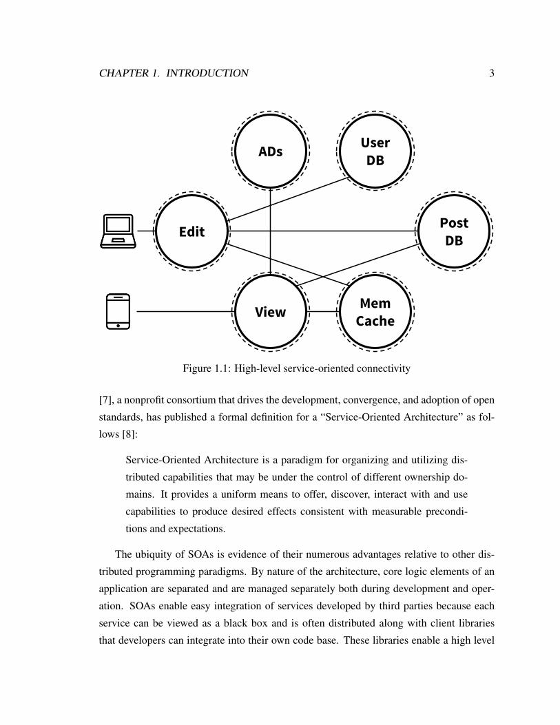
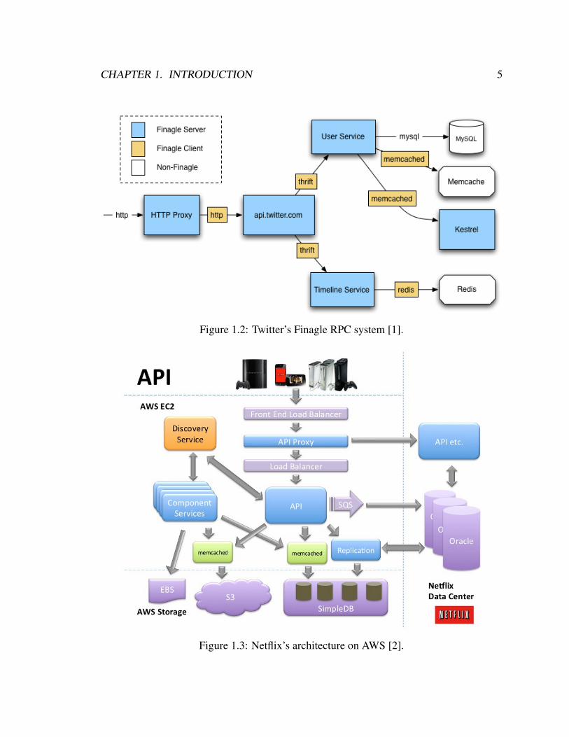
Figure 1.2 is a diagram created by Twitter [1] showing only a small portion of their ar-
chitecture to illustrate the operation of their protocol agnostic communication system called
Finagle. This diagram shows a few services interacting to create the Twitter application.
Similarly, Figure 1.3 is a diagram created by Netflix [2] illustrating their architecture on
Amazon’s cloud computing platform. For both of these designs, there exist several ser-
vices custom written for the application, as well as several services written by third parties.
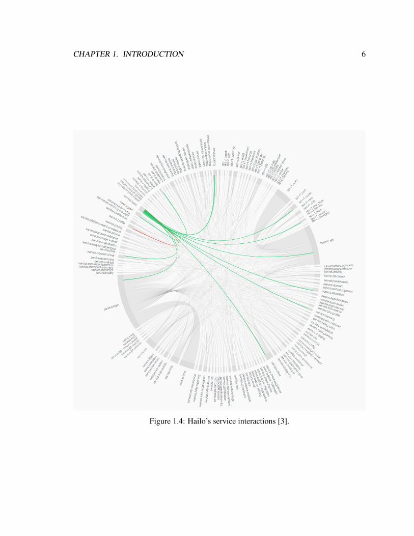
Figure 1.4 shows a service interaction diagram (occasionally referred to as “the wheel
of doom”) created by Hailo [3] listing interactions of the 146 services that comprise their
application. This diagram highlights one such service which utilizes 12 other services to
fulfill its function. Figures 1.2, 1.3, and 1.4 all show that when designing an application at
a high level, application developers divide the application’s functionality into services with
well-defined APIs to achieve modularity.
CHAPTER 1. INTRODUCTION 5
Figure 1.2: Twitter’s Finagle RPC system [1].
Figure 1.3: Netflix’s architecture on AWS [2].
CHAPTER 1. INTRODUCTION 6
Figure 1.4: Hailo’s service interactions [3].

CHAPTER 1. INTRODUCTION 7
1.2 High-Performance Interconnects
The highest level of network performance available today is found in supercomputing in-
terconnection networks such as Cray Cascade [11] and Gemini [12], IBM Blue Gene/Q
[13] and PERCS [14], and Mellanox InfiniBand [15]. These interconnects achieve high
bandwidth and predictably low latency while incurring minimal CPU overhead. For exam-
ple, InfiniBand networks manufactured by Mellanox Technologies achieve round-trip times
on the order of 2 µs and bandwidths as high as 100 Gbps [15]. The Cray Cascade system
scales the 92,544 nodes, achieves unidirectional latencies as low as 500 ns, and provides
93.6 Gbps of global bisection bandwidth per node [11]. In order to achieve the goal of
high network performance, this dissertation defines metrics of performance relative to the
highest performing interconnection networks.
One of the major strategies that supercomputers use to achieve high performance is
allowing applications to bypass the operating system and interact with the network interface
directly. This is called OS-bypass. All major high-performance computing fabrics have
taken this approach, such as those offered by Cray, IBM, Mellanox, Myricom, Quadrics,
etc. On top of better network performance, OS-bypass provides lower CPU overhead as
the kernel is freed of the task of managing network interface sharing. CPU overhead can
be further reduced by offloading network transport protocols to the network interface.
OS-bypass has one major ramification that limits its ability to be useful in traditional
schemes for implementing security and isolation. Bypassing the kernel (or hypervisor)
removes its ability to monitor, modify, rate limit, or block outgoing network traffic in an
effort to provide sender-side security and isolation features. This is commonly performed in
network virtualization software like VMware NSX [16] and Open vSwitch [17]. The work
of this dissertation embraces this ramification of OS-bypass and utilizes it as an advantage.
Achieving high network performance, both in terms of high bandwidth and predictably
low latency, is crucial to the advancement of future computing technologies. Speaking
about the topic in their article titled “It’s Time for Low Latency”, Rumble et al. [18] say:
Lower latency will simplify application development, increase web application
scalability, and enable new kinds of data-intensive applications that are not
possible today.

CHAPTER 1. INTRODUCTION 8
High-performance interconnection networks that enable high bandwidth and predictably
low latency already exist, however, the technologies found within these systems are not ad-
equately usable for the computing models ubiquitously used in modern data centers and
cloud computing environments. Until now, it has been assumed that there exists a funda-
mental trade-off between security and performance. This dissertation dispels this belief and
proposes a new distributed system architecture that provides both security and performance
with zero overhead on the CPU.
1.3 Contributions
This dissertation makes the following contributions:
• A service-oriented application model, called Sikker, is proposed that fits with modern
large-scale applications and increases the scalability of access control lists (ACLs)
by many orders of magnitude. This is the first work to present a service-oriented
network architecture that yields process-oriented authentication.
• A new network interface architecture, called the Network Management Unit (NMU),
is proposed that enforces Sikker security policies. The NMU increases message la-
tency by approximately 50 ns, is able to handle hundreds of Gbps of bandwidth, and
imposes zero overhead on the CPU.
• A new distributed rate-control algorithm, called Sender-Enforced Token and Rate
Exchange (SE-TRE), is proposed that provides strict service-oriented rate control.
SE-TRE has zero latency overhead at the 99.99th percentile, less than 0.3% band-
width overhead, and as an algorithm that can be implemented in the NMU imposes
zero overhead on the CPU.
1.4 Dissertation Outline
The remainder of this dissertation is as follows. Chapter 2 provides some background into
what the current state-of-practice and state-of-research are including their focus and direc-
tions. Chapter 3 describes the motivation behind this dissertation and explains the areas

CHAPTER 1. INTRODUCTION 9
where prior work is deficient and/or non-existent. Chapter 4 defines and describes Sikker
as a new distributed system architecture for efficient service-oriented computing. As an ab-
stract system architecture, this Chapter describes Sikker’s functionality and model, not its
implementation. Chapter 5 presents potential rate-control algorithms for implementation
within Sikker. Chapter 6 describes the architecture of a novel network interface controller,
called the Network Management Unit (NMU), that is a Sikker enforcement agent as it up-
holds the policies laid out by Sikker. Chapter 7 provides an evaluation of the access-control
efficiency of Sikker and the NMU. Similarly, Chapter 8 provides an evaluation of the rate-
control efficiency of Sikker and the NMU. Chapter 9 describes several optimizations and
improvements that can be implemented under the service-oriented programming model of
Sikker. Finally, Chapter 10 concludes this dissertation.

Chapter 2
Related Work
2.1 Supercomputing
For the sake of performance, modern supercomputers employ minimal security and iso-
lation mechanisms. For isolation, some fabrics use coarse-grained network partitioning
schemes that are efficient at completely isolating applications from each other but they
don’t provide a mechanism for controlled interaction between applications. This is espe-
cially problematic if the system offers shared services, such as a distributed file system
(e.g., Lustre [19]).
Some high-performance interconnects, namely InfiniBand, employ mechanisms for se-
cret key verification where the receiving network interface is able to drop packets that do
not present the proper access key that corresponds to the requested resource [20]. While
this scheme provides a mechanism for coarse-grained security, it does not provide net-
work isolation nor does it provide fine-grained security to cover the application’s security
requirements. As a result, the endpoints are susceptible to malicious and accidental denial-
of-service attacks and they still have to implement the required fine-grained security checks
in software.
Current research in the space of supercomputer multi-tenancy focuses on resource uti-
lization and fairness and makes little effort to provide security and isolation in the face of
malicious behavior. These proposals [21, 22, 23, 24, 25], while succeeding in their defined
goals, do not provide secure supercomputing systems in the presence of multi-tenancy.
10
CHAPTER 2. RELATED WORK 11
Furthermore, none of these proposals provide a scalable architecture on which large-scale
service-oriented applications can be built. Even with the advancements of these proposals,
supercomputers are still only useful for environments where security and isolation is not a
requirement which would imply implicit trust between all users.
2.2 Cloud Computing
In contrast to supercomputers, cloud computing facilities (e.g., Amazon Web Services [26],
Microsoft Azure [27], Google Cloud Platform [28], Heroku [29], Joyent [30]) are faced
with the most malicious of tenants. These facilities run applications from many thousands
of customers simultaneously, some as small as one virtual machine and others large enough
to utilize thousands of servers. These facilities must provide the highest level of security
and isolation in order to protect their clients from each other. Furthermore, these facili-
ties often have large sharable services that get used by their tenants for storage, caching,
messaging, load balancing, etc. These services also need to be protected from client abuse.
Network isolation mechanisms found in modern cloud computing facilities are net-
work partitioning schemes both physical (e.g., VLAN [31]) and virtual (e.g., VXLAN
[32], NVGRE [33]). These partitioning schemes are successful at completely isolating
applications from each other, but just like the partitioning schemes found in supercom-
puters, they don’t provide a mechanism for controlled interaction between partitions. In
efforts to bridge partitions, network virtualization software like OpenStack Neutron [34]
and VMware NSX [16] create virtualized switches (e.g., Open vSwitch [17]) and routers
that use network-oriented primitives as a mechanism for access control.
Current research in the space of cloud computing multi-tenancy uses hypervisor-based
pre-network processing to implement various types of security and isolation. While these
proposals [35, 36, 37, 38, 39, 40] achieve their desired goals of providing fair network re-
source sharing, they significantly increase message latency and CPU utilization and still
don’t provide fine-grained security and isolation. These proposals are often developed and
tested on network bandwidths an order of magnitude lower than the bandwidths achieved
on supercomputers (10 Gbps vs 100 Gbps) and may not be feasible at supercomputer band-
widths.
CHAPTER 2. RELATED WORK 12
NetBurst@ 1 Gbps
Nehalem@ 10 Gbps
Haswell@ 25 Gbps
Skylake@ 50 Gbps
0%
5%
10%
15%
20%
25%
30%
35%
40%
45%
50%
2005 2007 2009 2011 2013 2015 2017
CP
U O
verh
ead
Year
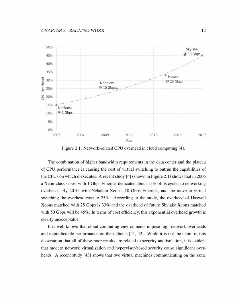
Figure 2.1: Network-related CPU overhead in cloud computing [4].
The combination of higher bandwidth requirements in the data center and the plateau
of CPU performance is causing the cost of virtual switching to outrun the capabilities of
the CPUs on which it executes. A recent study [4] (shown in Figure 2.1) shows that in 2005
a Xeon-class server with 1 Gbps Ethernet dedicated about 15% of its cycles to networking
overhead. By 2010, with Nehalem Xeons, 10 Gbps Ethernet, and the move to virtual
switching the overhead rose to 25%. According to the study, the overhead of Haswell
Xeons matched with 25 Gbps is 33% and the overhead of future Skylake Xeons matched
with 50 Gbps will be 45%. In terms of cost efficiency, this exponential overhead growth is
clearly unacceptable.
It is well known that cloud computing environments impose high network overheads
and unpredictable performance on their clients [41, 42]. While it is not the claim of this
dissertation that all of these poor results are related to security and isolation, it is evident
that modern network virtualization and hypervisor-based security cause significant over-
heads. A recent study [43] shows that two virtual machines communicating on the same

CHAPTER 2. RELATED WORK 13
host should expect 25-75 µs of round-trip latency. Similarly, a virtual machine commu-
nicating with a native operating system connected to the same 10 Gbps physical switch
should expect 35-75 µs of round-trip latency. The latency is significantly worse if the com-
munication is forced to tunnel through an intermediate host containing a virtual router in
order to cross the boundary between virtualized network partitions, as is done in OpenStack
Neutron [34].

Chapter 3
Motivation
In order to overcome the deficiencies of modern systems this dissertation calls for the de-
sign of a system that is highly optimized for large-scale service-oriented computing archi-
tectures. This is divided into two main topics: access control and rate control.
3.1 Access Control
An examination of the source code of a particular service reveals the implicit interaction
privileges it desires with other services. In most cases, the code expressing the desired in-
teractions does not contain IP addresses or TCP port numbers, but instead contains service
names, process identifiers, permission domains, and/or API commands. For example, from
the Twitter architecture, shown in Figure 1.2, the code might reveal the Timeline Service
desiring to communicate with the Redis service using its process #6 and using API com-
mand Get. Services written at Google use the “Borg name service” (BNS) that translates
high-level service-oriented identifiers into IP address and TCP port pairs to be used in their
ubiquitous RPC system [44].
The implicit service-level privileges expressed in the source code present the ideal level
at which permissions should be enforced as these privileges are derived from the applica-
tions themselves and represent the actual intent of the interacting services on the network.
14

CHAPTER 3. MOTIVATION 15
Protocol Source DestinationAddress Port Address Port
TCP 192.168.1.3 54321 10.0.2.10 123TCP 192.168.1.3 43215 10.0.2.10 456TCP 192.168.1.3 43215 10.0.3.10 456
Table 3.1: A network-oriented ACL (NACL) entry.
As will be described in this section, the available security and isolation techniques in mod-
ern data centers use multiple layers of indirection (e.g., DNS, IP-to-MAC translation) be-
fore permissions can be checked and enforced. This creates high operational complexity
and presents many opportunities for misconfiguration. Furthermore, these systems lose in-
formation about the original intent of the application, and thus cannot enforce the intended
permissions. The lack of inherent identity authenticity within the network forces develop-
ers to use authentication mechanisms (e.g., cryptographic authentication) that incur high
CPU overhead and are unable to properly guard against denial-of-service attacks due to the
lack of isolation. This section describes how current systems work and presents a proposal
for a better solution.
To moderate network access, modern network isolation mechanisms use access control
lists (ACLs). In the abstract form, an ACL is a list of entries each containing identifiers
corresponding to a communication mechanism and represent a permissions whitelist. For
access to be granted, each communication must match an entry in the ACL. The most
common type of ACL entry is derived from TCP/IP network standards. This network-
oriented style of ACL will further be referred to as an NACL. Table 3.1 shows an example
of NACL entries, commonly represented as a list of 5-tuples. The first entry states that
a packet will be accepted by the network if the protocol is TCP and it is being sent from
192.168.1.3 port 54321 to 10.0.2.10 port 123. The other entries vary the IP addresses and/or
the ports. Portions of a NACL can be masked out so that only a portion of the entry must
be matched in order for a packet to be accepted by the network.
A comparison between the NACL whitelisting mechanism and the implicit privileges
desired by services exposes the deficiencies of using any ACL system based on network-
centric identifiers such as protocols, network addresses, or TCP/UDP ports. One important
thing to notice is that the source entity is referenced by an IP address and optionally a port.

CHAPTER 3. MOTIVATION 16
Source DestinationService Service Processes Domains
TimelineService Redis 6, 17, 32 Get, Set
Table 3.2: A service-oriented ACL (SACL) entry.
For this system to work as desired, the system must know with absolute confidence that
the source entity is the only entity with access to that address/port combination and that
it is unable to use any other combination. This is hard to ensure because the notion of an
IP address is very fluid. While it is commonly tied to one network interface port, modern
operating systems allow a single machine to have many network interfaces, network inter-
faces can have more than one IP address, and/or multiple network interfaces can share one
or more IP addresses. There is no definitive way to determine the source entity based solely
on the source IP address. Another issue is the use of UDP and TCP ports, which are ab-
stract identifiers shared among all the processes on a given machine. Tying the permissions
to ports requires the source and destination to keep numerous open sockets proportional to
the number of permission domains required by the application.
ACL whitelisting has the right intent with its approach to security and isolation because
of its inherent implementation of the principle of least privilege [45] and its ability to pre-
vent denial-of-service attacks by filtering invalid traffic before it enters the network. How-
ever, the layers of indirection and loss of original intent imposed by using network-centric
ACLs yields security and isolation deficiencies for modern service-oriented applications.
In order to design a better system, this dissertation proposes creating an access control
scheme based directly on the implicit privileges desired by each service. The ACL entries
of this scheme exactly express the communication interactions of services and their APIs.
This service-oriented style of ACL will further be referred to as a SACL. As shown in
Table 3.2, the entry is a nested data structure that stores two lists for each source and
destination service pair. The first list specifies the set of destination processes within the
destination service that the source service is allowed to communicate with. Similarly, the
second list specifies the set of destination permission domains within the destination service
that the source service has access to. Because the lists are held separately this creates an
orthogonality between process access and permission domain access. In this example,

CHAPTER 3. MOTIVATION 17
repeated from the Twitter example shown in Figure 1.2, the TimelineService is able to
access the Redis service using process #6 and using the Get permission domain, among
others. SACLs make reasoning about network permissions much easier and don’t tie the
permission system to any underlying transport protocol or addressing scheme. It simply
enforces permissions in their natural habitat, the application layer.
A tremendous amount of security and isolation benefits are available to the endpoints if
the following system-level requirements are upheld for the SACL methodology:
SACL Requirements:
S.1 The network is a trusted entity under a single administrative domain.
S.2 The network is able to derive the identity of a process and it is impossible for a
process to falsify its identity.
S.3 The source is able to specify the destination as a service, process, and permission
domain.
S.4 Messages sent are only received by the specified destination.
S.5 The source service and process identifiers are sent with each message to the destina-
tion.
With these requirements upheld, the system inherently implements source and destination
authentication by which all received messages explicitly state the source entity’s identifi-
cation and are only delivered to the specified destination. Combined, source and destina-
tion authentication remove the need for complex authentication software in the application
layer. Furthermore, senders don’t need to use name servers to discover physical addressing
for desired destinations as they only need to specify the destination by its virtual identity
(i.e., service ID, process ID, and domain ID) and the network will deliver the message to
the proper physical location.

CHAPTER 3. MOTIVATION 18
3.2 Rate Control
Restricting which entities have access to particular resources is an essential component for
security and isolation. Another essential component is restricting the amount of access an
entity has with a particular resource. When applied to service-oriented architectures, this
equates to limiting the amount of communication one service has with another. Figure 3.1
shows an example of 6 services that interact to provide the functionality of two user facing
applications, similar to Figure 1.1. Also shown in Figure 3.1 is the desire to limit the rate at
which the Editor service and Viewer service are able to utilize the Post DB service. In this
figure, and in the rest of this dissertation, network bandwidth is the rate-based resource that
will be controlled, however, the observations, theories, and practices presented can equally
and easily be applied to any other rate-based resource (e.g., requests per second, operations
per second, etc.).
Viewer MemCache
ADs UserDB
PostDBEditor 25 Gbps
75 Gbps
Figure 3.1: High-level service-oriented rate limits

CHAPTER 3. MOTIVATION 19
The complex interactions of many distributed systems, predominantly cloud comput-
ing, require precise control over the amount of inter-service communication. Service-
oriented rate control is a desirable feature for numerous reasons. First, even though ser-
vices can be designed to satisfy the requests of many clients they have finite capabilities
which must not be exceeded. In order to ensure that their services aren’t oversubscribed
by malicious or faulty clients, service providers can use rate-control mechanisms to limit
the amount of communication from each client. Second, because the physical placement of
processes of the various client services might be unregulated or unknown, it is undesirable
to give priority to those client processes that happen to be closer to the destination. It is
desirable to give each service its fair share of bandwidth. Third, in cloud computing en-
vironments the definition of fair share typically comes with a price tag. Cloud computing
service providers often price their services in performance brackets and they don’t want
customers receiving more bandwidth than they paid for. Service-oriented rate control can
ensure that clients only receive what they pay for.
Due to the lack of service orientation in today’s systems, rate-control mechanisms get
applied directly to processes, containers, or virtual machines. The inability to adapt to
the demands of a distributed service results in either over-provisioning, which leaves the
receiving service at higher risk, or under-provisioning, which leaves the sending service
without enough network resources to complete its task. Instead of applying rate limits at
the process level, this dissertation makes the proposal to apply rate limits at the service
level to fit with the architecture of modern large-scale applications. This work measures
the service level rate as the aggregate bandwidth being sent from all processes in the source
service to all processes in the destination service. As each process is executing along its
own sequence of operations, which might be driven by events external to the service, the
rate required by an individual process may vary over time.
Distributed rate control is a difficult problem to solve because both entities (source and
destination services) are highly distributed entities potentially consisting of thousands of
processes each. Figure 3.2 shows a diagram of two services each containing three pro-
cesses. As shown, each process within the source service has a unique path through the
network for each process in the destination service. The total number of unique paths for a
pair of services is equal to the product of the number of processes in each service. Due to

CHAPTER 3. MOTIVATION 20
this potentially very large number of unique paths, using a feedback methodology as means
to monitor then enforce rate control is infeasible.
Distributed rate control is also difficult to solve because the processes of a service often
have a non-uniform usage of another service and programs go through phases where usage
of the destination service varies over time. Consider the case where Service #1 is given 30
units of aggregate bandwidth to communicate with Service #2. A naive distributed rate-
control algorithm might provision each source process with a fixed and equal allocation
of the aggregate rate limit, which would be 10 units of bandwidth per process. This naive
algorithm places too many limitations on the types of applications that can run under this
scheme as it only allows applications where all processes can complete their tasks under
their fixed rate allocation. Assume Process A wants to use 20 units of bandwidth while
Processes B and C only want 5. After some short period of time Process A lowers its usage
down to 5 units of bandwidth and Process C increases its usage to 20. This sequence is
acceptable because the aggregate rate limit is not violated during these periods of time and
during the transitions. This rate usage pattern makes any fixed allocation scheme (equal or
not) unsatisfactory as it can not adapt to the changing behavior of the program which in
turn starves the processes of the bandwidth they require to complete their tasks.
In this dissertation a novel service-oriented rate-control algorithm is proposed, called
Sender-Enforced Token and Rate Exchange (SE-TRE), that enforces rate control directly
in the network interface of the sending processes. The network interfaces collaboratively
exchange control information to dynamically adapt to the continuously changing rate usage
of the processes within a service. The class of rate-control algorithms presented in this
dissertation only provide the upper limit of the rate used by one distributed entity (e.g.,
source service) communicating with another distributed entity (e.g., destination service).
The aggregate rate limit is only designed to protect the destination entity. It is not the
intent to provide minimum rate guarantees (e.g., service level agreements), ensure that the
network links can handle the rate limit specified, or provide process-level load balancing.
These rate-control algorithms control the high-level interaction between the two entities
and assume the physical infrastructure was appropriately designed to provide the necessary
link-level bandwidths.

CHAPTER 3. MOTIVATION 21
ProcC
ProcB
ProcA
ProcE
ProcF
ProcD
Service 1 Service 2
Network
Figure 3.2: Two services each with three processes. Also shown are unique paths that existsfrom every source process to every destination process.
Chapter 4
Sikker
With the insights gained in Chapter 3, a new distributed system architecture is proposed,
called Sikker1, that formally defines the structure of distributed applications and the inter-
actions within applications. Sikker is strictly a service-oriented architecture and makes no
attempt to justify the boundaries of applications. As a service-oriented architecture, Sikker
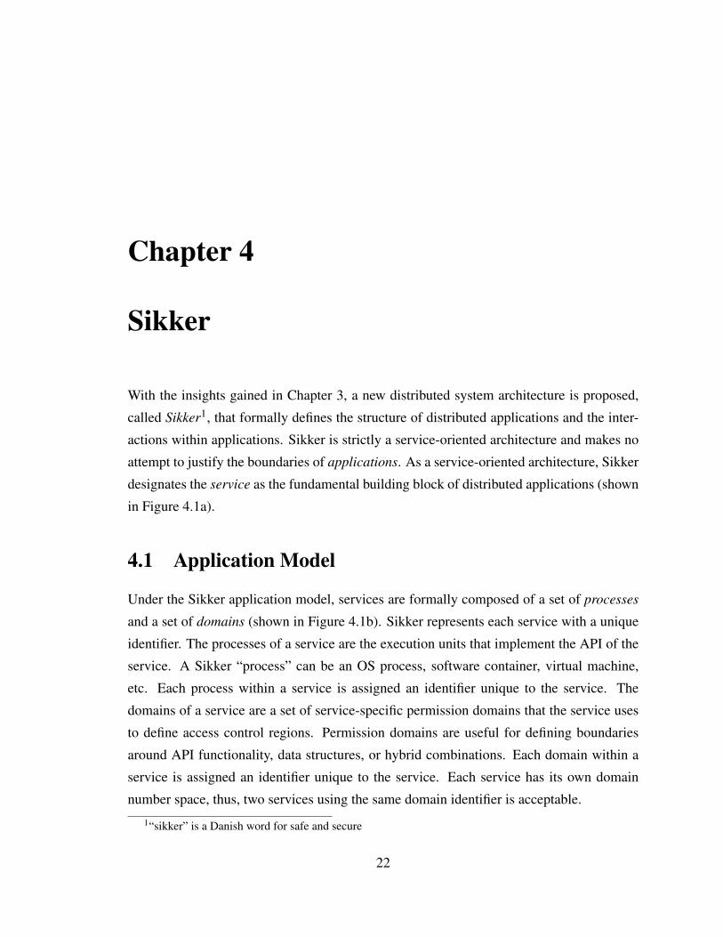
designates the service as the fundamental building block of distributed applications (shown
in Figure 4.1a).
4.1 Application Model
Under the Sikker application model, services are formally composed of a set of processes
and a set of domains (shown in Figure 4.1b). Sikker represents each service with a unique
identifier. The processes of a service are the execution units that implement the API of the
service. A Sikker “process” can be an OS process, software container, virtual machine,
etc. Each process within a service is assigned an identifier unique to the service. The
domains of a service are a set of service-specific permission domains that the service uses
to define access control regions. Permission domains are useful for defining boundaries
around API functionality, data structures, or hybrid combinations. Each domain within a
service is assigned an identifier unique to the service. Each service has its own domain
number space, thus, two services using the same domain identifier is acceptable.
1“sikker” is a Danish word for safe and secure
22

CHAPTER 4. SIKKER 23
AppApp App
SvcSvc SvcSvcSvc
(a) Applications are composed of Services. Services can be shared by multiple applications.
DomProc
Svc
Proc Dom Dom
(b) Services are composed of Processes and Domains.
Figure 4.1: Services are formally composed of a set of processes and a set of domains.
CHAPTER 4. SIKKER 24
Table Key Value
Mammals pet dog
Engineering department Electrical
Locations school California
Companies internship Google
Sports best wakeboarding
Engineering tool oscilloscope
Sports boring baseball
Locations born Utah
Mammals fastest cheetah
Companies career HPEAPI Commands: Get, Set, Delete
Bill KVS
John Mendel
GillAl
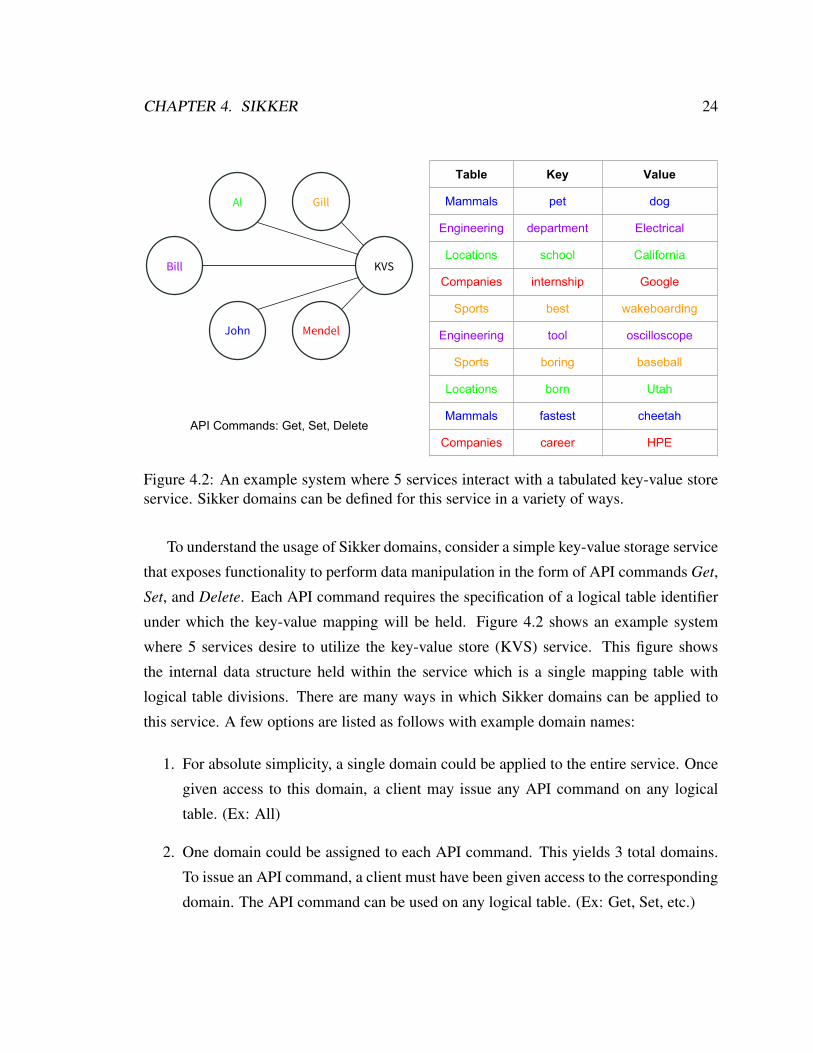
Figure 4.2: An example system where 5 services interact with a tabulated key-value storeservice. Sikker domains can be defined for this service in a variety of ways.
To understand the usage of Sikker domains, consider a simple key-value storage service
that exposes functionality to perform data manipulation in the form of API commands Get,
Set, and Delete. Each API command requires the specification of a logical table identifier
under which the key-value mapping will be held. Figure 4.2 shows an example system
where 5 services desire to utilize the key-value store (KVS) service. This figure shows
the internal data structure held within the service which is a single mapping table with
logical table divisions. There are many ways in which Sikker domains can be applied to
this service. A few options are listed as follows with example domain names:
1. For absolute simplicity, a single domain could be applied to the entire service. Once
given access to this domain, a client may issue any API command on any logical
table. (Ex: All)
2. One domain could be assigned to each API command. This yields 3 total domains.
To issue an API command, a client must have been given access to the corresponding
domain. The API command can be used on any logical table. (Ex: Get, Set, etc.)
CHAPTER 4. SIKKER 25
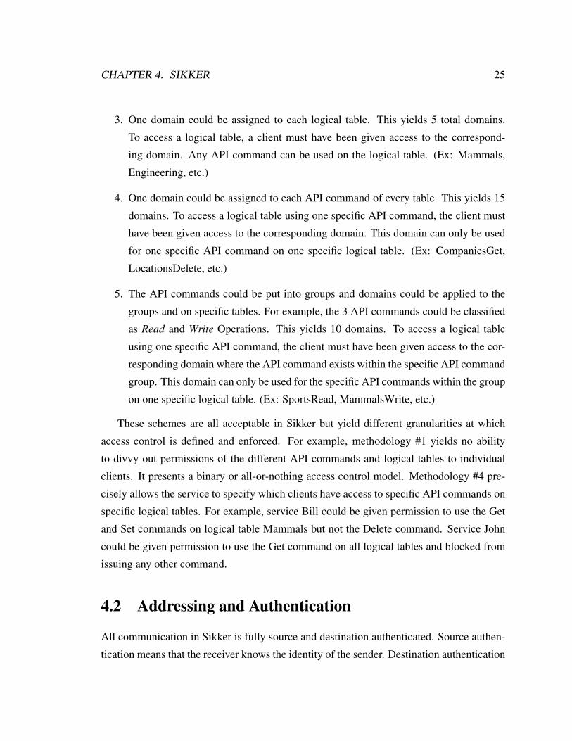
3. One domain could be assigned to each logical table. This yields 5 total domains.
To access a logical table, a client must have been given access to the correspond-
ing domain. Any API command can be used on the logical table. (Ex: Mammals,
Engineering, etc.)
4. One domain could be assigned to each API command of every table. This yields 15
domains. To access a logical table using one specific API command, the client must
have been given access to the corresponding domain. This domain can only be used
for one specific API command on one specific logical table. (Ex: CompaniesGet,
LocationsDelete, etc.)
5. The API commands could be put into groups and domains could be applied to the
groups and on specific tables. For example, the 3 API commands could be classified
as Read and Write Operations. This yields 10 domains. To access a logical table
using one specific API command, the client must have been given access to the cor-
responding domain where the API command exists within the specific API command
group. This domain can only be used for the specific API commands within the group
on one specific logical table. (Ex: SportsRead, MammalsWrite, etc.)
These schemes are all acceptable in Sikker but yield different granularities at which
access control is defined and enforced. For example, methodology #1 yields no ability
to divvy out permissions of the different API commands and logical tables to individual
clients. It presents a binary or all-or-nothing access control model. Methodology #4 pre-
cisely allows the service to specify which clients have access to specific API commands on
specific logical tables. For example, service Bill could be given permission to use the Get
and Set commands on logical table Mammals but not the Delete command. Service John
could be given permission to use the Get command on all logical tables and blocked from
issuing any other command.
4.2 Addressing and Authentication
All communication in Sikker is fully source and destination authenticated. Source authen-
tication means that the receiver knows the identity of the sender. Destination authentication

CHAPTER 4. SIKKER 26
means the sender is guaranteed that only the specified destination is able to receive the mes-
sage. Similar to other networks, processes in Sikker reside at physical locations specified
by physical addresses. However, in Sikker, processes are referenced by virtual addresses
that specify both the service and the process. When a process desires to send a message on
the network, it does not specify its own identity as the source. Instead, Sikker derives its
identity, consisting of both service and process, and attaches it to the message.
When specifying a destination for a message, the source process specifies the desti-
nation by three things: a service, a process within the service, and a domain within the
service. Combined, the source and destination specifications are attached to every message
transmitted on the network. Sikker guarantees that the message will only be delivered to
the specified destination. Receiving processes are able to inspect the source specification
in the message to explicitly know the source’s identity.
Under the Sikker security model, processes need not be concerned about physical ad-
dressing in the network. Processes only use service-oriented virtual network addresses
when referencing each other. Sikker performs the virtual-to-physical translations needed
for transmission on the network. Name servers are therefore not needed in Sikker. Through
Sikker, each process has the high-level identification for the destinations it will be commu-
nicating with.
4.3 Fixed Permissions
Each process within a service inherits all the permissions of the service to which it belongs.
In order for a process to be able to transmit a message to a specific destination, the service of
the sending process must have permission to access the specified process and domain within
the specified destination service. Sikker performs permission checks before messages enter
the network and for every message. Because the interaction policies of modern large-scale
distributed systems are constantly in flux, Sikker allows processes and domains to be added
and removed from services dynamically during runtime. When a new process is created, it
inherits all the permissions of the service to which it belongs. Any time the permissions of
a given service change, the change is reflected in all processes of the service.
Figure 4.3 shows a Sikker system that is performing access control at the injection point

CHAPTER 4. SIKKER 27
Sikker
Proc
Proc
NOS
Proc
Proc
Proc
Proc
tx_message: dst: [KVS, 27, MammalsSet] payload: “pet=cat”
rx_message: src: [Bill, 101] dst: [KVS, 27, MammalsSet] payload: “pet=cat”
Service: BillProcess: 101
Service: KvsProcess: 27
✓
Service: JohnProcess: 72
tx_message: dst: [KVS, 27, MammalsSet] payload: “pet=fish”
Figure 4.3: A Sikker system performing sender-enforced access control.
of the network. This figure highlights methodology #4 from the key-value store example
in Figure 4.2. In this figure, process #101 from the Bill service is granted access to set the
key-value mapping for “pet=cat” in the Mammals logical table of the KVS service. During
this transaction there exists source and destination authentication. The KVS service is
guaranteed that the Bill service had the proper permission to perform the transaction. The
KVS service did not have to perform any authentication or permissions checking itself.
Because of this, the KVS service can process the request immediately without wasting any
CPU cycles guarding itself from the network. Also in the figure is process #72 of the John
service attempting to perform a similar request. Due to a lack of permissions Sikker stops
this request before it enters the network. The KVS service is unaware of and is unaffected
by this attempt.
Figure 4.4 is an example service interaction graph under the Sikker application model.
This diagram shows three services, each with a few processes and a few domains. Solid
lines connect services to their corresponding processes and domains and connects processes
to their corresponding hosts. As shown, and widely used in practice, processes from the

CHAPTER 4. SIKKER 28
H1
S1:P1
S1
S1:D2
S1:D1
S3:P1
H2
S2:P1
S2
S3:P2
S2:D1
H4
S3:D2
S3
S3:D1S3:P3
H5
H3
S1:P2
S1:D3
=Service
=Process
=Domain
=Host
Figure 4.4: An example service interaction graph. Solid edges represent assignment anddashed edges represent permissions. Highlighted is one successful permission set beingused.

CHAPTER 4. SIKKER 29
same service and/or different services may overlap on the same host. Dashed lines show
the permissions given to services. These lines originate at a service and end at a process
or a domain. Highlighted in the diagram is a successful usage of a permission set where
Service 2 Process 1 (S2,P1) sends a message to Service 1 Process 2 using the Domain 1
(S1,P2,D1).
4.4 One Time Permissions
The use of request-response protocols is ubiquitous in service-oriented applications. In
this environment, many services only become active when they receive requests from other
services. This master/slave interaction is achieved via request-response protocols. Cloud
computing providers often provide services like this with many features to increase the
productivity of their tenants. These services (e.g., Amazon S3[46], Google BigTable[47],
Microsoft Azure Search[48]) can be very large and provide functionality to many thousands
of clients.
To increase scalability and to fit better with large-scale request-response driven multi-
tenant systems, Sikker contains a mechanism for one-time-permissions (OTPs). An OTP is
a permission generated by one process and given to another process to be used only once.
An OTP specifies a service, process, and domain as a destination and can only be created
using the permissions that the creating process already has. When a process receives an
OTP from another process, it is stored by Sikker in a temporary storage area until it gets
used by the process, at which time Sikker automatically deletes the permission. Because an
OTP fully specifies the destination, the process using it specifies the OTP by its unique ID
instead of specifying the destination as a service, process, and domain. Only the process
that received the OTP can use it. OTPs cannot be shared across the processes in a service.
For an example of using OTPs, consider Service 1 in Figure 4.4 which has no permis-
sions assigned to it, thus, cannot send messages on the network. Assume its API specifies
that users of the service must give it an OTP with each request. Now assume that Service
2 Process 1 (S2,P1) wishes to send a request to Service 1 Process 2 Domain 1 (S1,P2,D1).
When it formulates its request, it generates an OTP (shown in Figure 4.5a) that specifies
itself (S2,P1) with Domain 1 as the recipient (S2,P1,D1). The message will be sent as usual

CHAPTER 4. SIKKER 30
H1
S1:P1
S1
S1:D2
S1:D1
S3:P1
H2
S2:P1
S2
S3:P2
S2:D1
H4
S3:D2
S3
S3:D1S3:P3
H5
H3
S1:P2
S1:D3
2:1:1
(a) An OTP is generated by the requester.
H1
S1:P1
S1
S1:D2
S1:D1
S3:P1
H2
S2:P1
S2
S3:P2
S2:D1
H4
S3:D2
S3
S3:D1S3:P3
H5
H3
S1:P2
S1:D3
2:1:1
(b) The OTP is sent to the responder.
H1
S1:P1
S1
S1:D2
S1:D1
S3:P1
H2
S2:P1
S2
S3:P2
S2:D1
H4
S3:D2
S3
S3:D1S3:P3
H5
H3
S1:P2
S1:D3
2:1:1
(c) The OTP is received by the responder.
H1
S1:P1
S1
S1:D2
S1:D1
S3:P1
H2
S2:P1
S2
S3:P2
S2:D1
H4
S3:D2
S3
S3:D1S3:P3
H5
H3
S1:P2
S1:D3
2:1:1
(d) The OTP is used by the responder.
Figure 4.5: The 4 stages of generating, sending, receiving, and using an OTP.
and the OTP will be sent with it (shown in Figure 4.5b). (S1,P2) will receive the OTP with
the request (shown in Figure 4.5c) and when the response is ready to be sent, it simply uses
the OTP to send it (shown in Figure 4.5d). After the response is sent, Sikker deletes the
OTP.
For a real-world example, consider the case of the Hailo application as shown in Figure
1.4. The service with the largest number of service-to-service connections is the “login”
service. This service performs the login functionality for users using the Hailo service.
Nearly all other services access this service. As such, using fixed permissions would require
the service to hold permissions for nearly all other services. As a slave-oriented service,
CHAPTER 4. SIKKER 31
login functionality becomes active only when another service needs to log a user in or
verify that a user has already logged in. Instead of using fixed permissions, this service
could just require all client services to provide an OTP along with each login request. In
this way, the service doesn’t need to hold any fixed permissions.
Another interesting example of using OTPs is allowing one service to act on behalf of
another service. This is called a 3-way OTP. Given the same example as before, assume
that (S2,P1) wants the response to be sent to (S3,P3,D2) instead of itself. Because it has
the proper permissions, it is able to create the OTP with this recipient. The effect is that
(S2,P1) sends the request to (S1,P2,D1), then (S1,P2) sends the response to (S3,P3,D2).
Continuing from the Hailo example above, 3-way OTPs could be used to reduce messaging
latency by service A using a OTP on the “login” service to send a user’s status to service
B that is expecting the data. In this case, it reduces the number of network transactions
from 3 to 2 for service A sending the user’s log in information to service B. This increases
performance in terms of latency, bandwidth, and CPU utilization.
4.5 Rate Control
Sikker provides a mechanism upon which service-to-service rate limits can be enforced.
Rate limits in Sikker specify a source service and a destination service. The enforced rate
limit specifies the maximum amount of bandwidth that can be sent by the source service
to the destination service. The rate limit is independent of the size of both the source and
destination services. When a rate limit is enabled, Sikker guarantees that the specified
aggregate rate will not be exceeded. If the source service attempts to exceed its designated
rate, further messages will be denied access to the network until the aggregate rate limit
has dropped below to specified limit. As each particular process of a service has a varying
amount of rate usage to the destination, the rate each process experiences is a dynamic
value that can increase or decrease upon demand so long as the aggregate rate limit is not
exceeded. When rate limits are not specified, Sikker does not impede traffic being sent on
the network and the maximum bandwidth between the pair of services is only limited by
the underlying network infrastructure.

CHAPTER 4. SIKKER 32
Bill KVS
John Mendel
GillAl
35 Gbps
10 Gbps
15 Gbps
25 Gbps15 Gbps
Figure 4.6: Example of assigning unidirectional service-level rate limits.
Figure 4.6 shows an example of assigning rate limits to services. The example is re-
peated from the key-value store example shown in Figure 4.2. It could be the case that the
KVS service only has 100 Gbps of total processing power. Using Sikker’s service-oriented
rate control it can be guaranteed that this isn’t exceeded. Another scenario might be that
the KVS service has plenty of processing power enough to cover far more than the sum of
all client allocations, however the service desires to limit its clients’ access rate based on
the amount of money being paid monthly by the clients. Sikker rate limits can be used for
this as well. In most cases, it makes sense to apply rate limits only in the request direction
for request-response protocols, however, there is no restriction against bidirectional rate
limiting.
4.6 Network Operating System
As a system designed for a single administrative domain, Sikker requires the existence
of a network operating system or NOS (sometimes referred to as a cluster coordinator,
cluster scheduler, or cluster manager) to act as a trusted system-wide governor. The NOS
creates the services running on the network, establishes their permissions, and distributes
the proper permissions to the proper entities in the system. The NOS is responsible for
interacting with the cluster users (i.e., those who run services on the cluster) via a secure

CHAPTER 4. SIKKER 33
externally accessible user interface. The specific placement, implementation, and fault
tolerability of the NOS is beyond the scope of this work as nearly all large-scale cluster
coordinators have already solved these issues [44, 49, 50].
When a user desires to start a new service they must first define the service in terms
of processes and domains. While the service, its processes, and its domains are all repre-
sented with abstract identifiers, process definitions must also specify a program to be run
(e.g., the program binary) and how to run it (e.g., program arguments, working directory,
environment variables, etc.).
If the service will be providing functionality to other services, the user must create a set
of access portals for the service. Each portal contains a subset of the total processes and
domains within the service that an eligible other service will be able to use. For example,
consider the key-value store described in Section 4.1 and Figure 4.2. The user that started
the KVS service could have created a password protected portal, called AccessForBill, con-
taining processes 3, 6, and 9 and permission domains CompaniesGet and LocationsDelete
(domain methodology #4).
The next step is to determine which of the other services the starting service will require
functionality from. The user might explicitly know this information (presumably because
they or their colleagues started those services) or they may need to retrieve this information
from the NOS. For instance, a user starting several services designed to operate with each
other will know the services IDs of all the services that comprise their application. In
contrast, a user starting a service in a cloud computing environment will need to get the
service identification of a storage service (e.g., Amazon S3[46]) provided by the system
operator (e.g., Amazon Web Services[26]).
After having the service identifiers, the user must specify which portals it desires to
utilize on the other services and, if required, present valid credentials to use those portals.
Continuing the previous example, assume the KVS service defined the AccessForBill por-
tal and was started. Later, the user starting the Bill service identifies that it will require
interaction with the KVS service and provides the NOS with AccessForBill and the proper
password. When the Bill service is started it will contain fixed permissions to the KVS
service using processes 3, 6, and 9 and permission domains CompaniesGet and Locations-
Delete. The KVS service ID and the IDs of the processes and domains within the portal

CHAPTER 4. SIKKER 34
can be directly given to the processes of the Bill service via program arguments.
There are instances where the domains of a service need to be created dynamically as
the service runs. For example, a storage service might create a set of domains for each client
service utilizing the storage functionality. Alternatively, a storage service might create a
new set of domains for a new data set that will be stored within the service. To accomplish
this, the NOS allows users to define a set of policies upon which the NOS decides when
and how to create or remove domains for their service while it runs. When the domains of
a service are modified, the service itself receives a message from the NOS informing it of
the change so that it knows how to act accordingly.
4.7 Connectivity Model
For the sake of comparison, a connectivity model for large-scale distributed applications
is used to model systems of any size. For a given number of host machines, this model
builds a connectivity graph with services, processes, and domains based on configurable
parameters. The parameters of this connectivity model are shown in Table 4.1. As an
example, consider a system comprised of 131,072 (i.e., 217) hosts. Under this configuration
each host has 16 processes that use the NMU, thus, there are over 2 million processes in
the system using Sikker. Since there are 512 processes per service, there are 4,096 total
services, each having 256 domains. Each service connects with 819 other services (20%
of 4,096) and each service connection is comprised of 333 processes (65% of 512) and 64
domains (25% of 256).
Processes per NMU 16Processes per service 512Domains per service 256
Service coverage 20%Process coverage 65%Domain coverage 25%
Table 4.1: Connectivity parameters for the service interaction model.
This is a rough estimation of the combination of workloads from data centers, cloud
computing, and supercomputing. In cloud computing environments, there are several very

CHAPTER 4. SIKKER 35
big services but the vast majority of services are small. Small services come from small
clients, thus, the inter-process connectivity they require is minimal. The big services that
satisfy the requirements of many clients can use the OTP mechanism described in Section
4.4, thus, they will not need fixed permissions for communicating with their clients.
Large singly-operated data centers (e.g., Facebook) more closely approach this connec-
tivity model as they employ many large services. The majority of modern large-scale web
services fit within approximately 1,000 processes, however, they only require connection
with approximately 10-20 other services.
Supercomputers have very little connectivity between services, however, the services
themselves can consume enormous portions of the system. Besides services densely con-
necting with themselves, scientific supercomputing workloads don’t exhibit system-wide
dense connectivity.
4.8 Scalability
This section evaluates the scalability of SACLs under the Sikker methodology. In general,
the amount of state needed to represent a set of permissions can be expressed as
E = A×R (4.1)
where E is the total number of ACL entries, A is the number of agents holding permissions,
and R is the number of resources being accessed by each agent. The NACL methodology
is compared to the SACL methodology with the following symbols:
st : Total services
ps : Processes per service
ds : Domains per service
sa : Services accessed by each service
pa : Processes per service accessed by each service

CHAPTER 4. SIKKER 36
da : Domains per service accessed by each service
ph : Processes per host
SACLs have two scalability advantages over NACLs. First, SACLs apply permissions
directly to services instead of processes. Second, SACLs provide orthogonality between
the access to processes and the access to domains. The amount of ACL entries needed in
the NOS is first evaluated. For NACLs the number of permission holding agents is equal
to the total number of processes in the system. Because NACLs have no knowledge of
services, they assume each process has its own domain set. The resulting expression is:
Nnacl = st × ps︸ ︷︷ ︸A
×sa × pa ×da︸ ︷︷ ︸R
(4.2)
where N is the number of ACL entries in the NOS. In contrast, the expression for SACLs
is:
Nsacl = st︸︷︷︸A
×sa × (pa +da)︸ ︷︷ ︸R
(4.3)
In Figure 4.7 the left Y-axis and the solid lines show a comparison between NACLs
and SACLs for the storage requirements of the NOS using the connectivity model from
Section 4.7. This shows that SACLs maintain savings of well over 4 orders of magnitude
compared to NACLs. For example, if each ACL entry consumes 4 bytes, and the system
size is 131,072 hosts, NACLs require 146 TB of storage while SACLs only require 5.33
GB.
The amount of storage needed on each host scales differently than the storage required
in the NOS. For both NACLs and SACLs, the number of permission holding agents is the
number of resident processes. The resulting expression for NACLs is:
Hnacl = ph︸︷︷︸A
×sa × pa ×da︸ ︷︷ ︸R
(4.4)

CHAPTER 4. SIKKER 37
2k 4k 8k 16k 32k 64k 128kHosts
105106107108109
10101011101210131014
Tota
l ACL
s
NACLSACL
104
105
106
107
108
109
ACLs
per
hos
t
NACLSACL
Figure 4.7: Scalability comparison between NACLs and SACLs. The left Y-axis and solidlines show the storage requirements on the NOS. The right Y-axis and dashed lines showthe storage requirements at each host.
where H is the number of ACL entries on each host. In contrast, the expression for SACLs
is:
Hsacl = ph︸︷︷︸A
×sa × (pa +da)︸ ︷︷ ︸R
(4.5)
In Figure 4.7 the right Y-axis and the dashed lines show a comparison between NACLs
and SACLs for the storage requirements at each host. This shows that SACLs maintain
savings of over 2 orders of magnitude compared to NACLs. For example, if each ACL
entry consumes 4 bytes, and the system size is 131,072 hosts, NACLs requires 1.12 GB of
storage while SACLs only require 20.8 MB.
4.9 Summary
Sikker’s security model is more straight forward than other approaches because the policies
on which it is established are derived directly from the applications themselves, instead of
being tied to specific network transport mechanisms. Sikker enforces security and isolation

CHAPTER 4. SIKKER 38
at a much finer granularity than current systems, provides inherent source and destination
authentication, implements the principle of least privilege [51], and makes reasoning about
service-oriented permissions easier.
Sikker’s sender-enforced isolation mechanism removes the ability for denial-of-service
attacks between services that don’t have permission to communicate. This isolation mecha-
nism creates a productive programming environment for developers since they can assume
that all permission checks were performed at the sender. In this environment, developers
are able to spend less time protecting their applications from the network and more time
developing core application logic.
The scalability benefits of Sikker’s service-oriented permission scheme yields signif-
icant system wide savings as well as savings at each endpoint. For a NOS holding the
permissions of an entire system, the difference between 146 TB and 5.33 GB allows the
permissions data to reside in a single DIMM of DRAM rather than multiple racks worth of
DRAM. Besides the obvious cost savings, this also presents enormous performance benefits
while operating on the data set. Managing a large-scale system with NACLs is rightfully
considered a “Big Data” application. In contrast, managing the same system with SACLs
can be done on an average laptop.
The amount of storage savings SACLs provide at each endpoint creates a great opportu-
nity for performance gain. While NACLs require 1.12 GB of storage at each point, SACLs
require only 20.8 MB which is within the storage capability of on-chip SRAM. Being able
to use only on-chip SRAM at each endpoint significantly reduces system cost and increases
performance.

Chapter 5
Rate Control Algorithms
This chapter describes the mechanics and operation of six different rate-control schemes
which will be evaluated as potential candidate algorithms for use in Sikker. The basis of
these algorithms was chosen to explore the space of distributed rate control with respect to
high-performance computing. This topic has not been previously covered because, prior
to Sikker, environments that support high-performance computing have not had formally
defined distributed entities that share permissions. The new computing model has yielded
the need for an efficient distributed rate control algorithm to regulate the communication
between services.
Rate control is provided using token buckets [52] implemented in the system in various
locations depending on the algorithm. In their basic form, token buckets (as shown in
Figure 5.1), have a rate Rt at which the bucket of size Sb is filled with tokens. Once full,
additional tokens are thrown away. When an outgoing packet desires to be sent it must wait
until there are enough tokens in the bucket to cover its size. When the packet is sent, the
corresponding number of tokens are consumed. It is possible for a token to represent a bit,
byte, phit, flit, or packet. This dissertation designates a token to represent one phit, which
is the amount of data handled in a single clock cycle [53]. Sikker defines the service-to-
service rate as the aggregate rate between all source processes to all destination processes.
The rate limit applied to the aggregate usage is denoted as Ra.
The six algorithms presented use variables which control their operation and efficiency.
Table 5.1 lists the global variables as well as the variables used in the algorithms. Many of
39

CHAPTER 5. RATE CONTROL ALGORITHMS 40
Rt
Rp
Sb
Figure 5.1: A token bucket with size Sb being filled at rate Rt .
the variables are shared across algorithms.
5.1 Nothing Enforced (NE)
The Nothing Enforced algorithm (shown in Figure 5.2) is simply to do nothing. It doesn’t
provide any protection for the destination service, thus it does not produce correct be-
haviour. It allows all source processes to send to the destination processes at whatever rate
they desire. While this algorithm is obviously a bad choice, it does however have zero
overhead which makes it a good comparison point.
5.2 Relay Enforced (RE)
The Relay Enforced algorithm (shown in Figure 5.3) appoints Nr intermediate entities as
relay devices through which all traffic is tunneled flowing from the source service to the
destination service. The minimum number of relays is the aggregate rate limit Ra divided

CHAPTER 5. RATE CONTROL ALGORITHMS 41
Symbol Description Algorithm(s)Sb Maximum number of tokens per token bucket -Rt Rate at which a token bucket fills -Ra Maximum aggregate rate limit -Nr Number of relays employed RERr Rate capability of an individual sender or relay RENo Number of outstanding requests per relay RE
T hlow Low token bucket threshold SE-TE, SE-RE, SE-TRENpeers Number of peers for parallel requests SE-TE, SE-RE, SE-TRE
Ft Token ask factor SE-TE, SE-TRENt Current number of tokens in the bucket SE-TE, SE-RE, SE-TRE
Task Number of tokens asked for per peer SE-TE, SE-TRET ht Token giveaway threshold SE-TE, SE-TRETgive Number of tokens to give to requesting peer SE-TE, SE-TREFr Rate ask factor SE-RE, SE-TRE
Rask Amount of rate asked for per peer SE-RE, SE-TRET hr Rate giveaway threshold SE-RE, SE-TREFmr Maximum rate giveaway factor SE-RE, SE-TRERgive Amount of rate to give to requesting peer SE-RE, SE-TRE
Table 5.1: Rate-control variables
ProcC
ProcB
ProcA
ProcE
ProcF
ProcD
Service 1 Service 2
Network
Figure 5.2: Nothing Enforced (NE) rate-control algorithm.
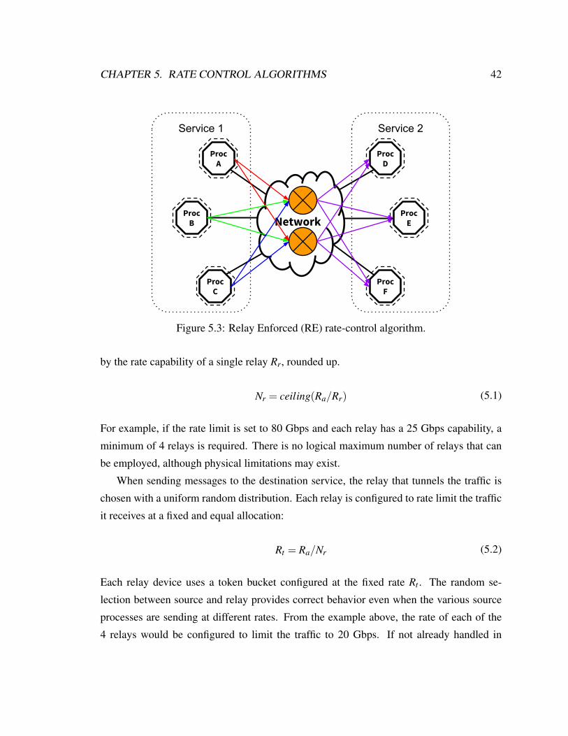
CHAPTER 5. RATE CONTROL ALGORITHMS 42
ProcC
ProcB
ProcA
ProcE
ProcF
ProcD
Service 1 Service 2
Network
Figure 5.3: Relay Enforced (RE) rate-control algorithm.
by the rate capability of a single relay Rr, rounded up.
Nr = ceiling(Ra/Rr) (5.1)
For example, if the rate limit is set to 80 Gbps and each relay has a 25 Gbps capability, a
minimum of 4 relays is required. There is no logical maximum number of relays that can
be employed, although physical limitations may exist.
When sending messages to the destination service, the relay that tunnels the traffic is
chosen with a uniform random distribution. Each relay is configured to rate limit the traffic
it receives at a fixed and equal allocation:
Rt = Ra/Nr (5.2)
Each relay device uses a token bucket configured at the fixed rate Rt . The random se-
lection between source and relay provides correct behavior even when the various source
processes are sending at different rates. From the example above, the rate of each of the
4 relays would be configured to limit the traffic to 20 Gbps. If not already handled in

CHAPTER 5. RATE CONTROL ALGORITHMS 43
ProcC
ProcB
ProcA
ProcE
ProcF
ProcD
Service 1 Service 2
Network
Figure 5.4: Sender-Enforced - Fixed Allocation (SE-FA) rate-control algorithm.
the networking infrastructure, a simple credit-based flow-control [53] scheme can be em-
ployed from source processes to relay devices to prevent the relays’ queues from getting
overwhelmed. The credit scheme limits the number of outstanding messages from each
sender to No.
This algorithm provides correct behaviour as it is impossible for the senders to com-
municate at a rate higher than the configured aggregate rate limit. However, this algorithm
induces a bandwidth overhead of at least 100% as each packet is relayed through an inter-
mediate device requiring two network transactions. Queuing latencies will also exist in the
relay devices when multiple senders randomly choose the same relay device. Statistically,
this affects the average latency very little, however the tail latency suffers severely.
5.3 Sender-Enforced - Fixed Allocation (SE-FA)
For all Sender-Enforced algorithms one token bucket is co-located with each process in the
source service.
Using a Fixed Allocation (shown in Figure 5.4) gives each token bucket a fixed portion
of the aggregate rate and the sum of all token bucket rates is equal to the aggregate rate

CHAPTER 5. RATE CONTROL ALGORITHMS 44
ProcC
ProcB
ProcA
ProcE
ProcF
ProcD
Service 1 Service 2
Network
Token Exchange Protocol
Figure 5.5: Sender-Enforced - Token Exchange (SE-TE) rate-control algorithm.
limit. These rates can be distributed equally or unequally.
This algorithm provides correct behavior as the aggregate rate limit cannot be violated.
It also has zero bandwidth overhead as messages flow directly from source to destination
and there is no auxiliary control messages being sent. When each source process sends at
a rate that is less than the rate at which its corresponding token bucket fills, this algorithm
provides zero latency overhead. However, any process that tries to send at a rate higher
than its token bucket fills will see an infinite amount of latency because its messages will
wait for an increasingly longer time and it will never recover. This is the case even when
the desired rate doesn’t cause the aggregate rate to exceed the limit.
5.4 Sender-Enforced - Token Exchange (SE-TE)
The Token Exchange algorithm (shown in Figure 5.5) augments the baseline Fixed Allo-
cation algorithm by allowing each token bucket to ask its peer token buckets for tokens
during times of need. To accomplish this, each token bucket has a threshold T hlow that
triggers when the amount of tokens gets too low. In this scenario, the token bucket chooses
Npeers random peers from which it will ask for additional tokens. For each request, the
CHAPTER 5. RATE CONTROL ALGORITHMS 45
token bucket asks for tokens using the following equation:
Task = ((Sb −Nt)/Npeers)×Ft (5.3)
where Ft is the token ask factor and Nt is the current amount of tokens in the bucket. The
token ask factor creates an opportunity to vary the algorithm to be more greedy or more
conservative. A token ask factor of greater than 1.0 means the algorithm may receive
more tokens than it is able to handle, thus wasting tokens. However, it may be found
that statistically, this greedy approach is beneficial. For example, assuming Ft = 1.0 and
Npeers = 3, if the bucket size is 500 but there only 200 tokens in the bucket, each request
would ask for 100 tokens. When Ft = 1.0 a token bucket asks for exactly enough tokens to
fill its bucket.
When a token bucket receives a request from one of its peers asking for tokens, it
decides whether it wants to give tokens away or not, and if so, how many to give. Each
token bucket has a threshold T ht which is the minimum amount of tokens needed before
it is willing to give away any of its tokens. If this threshold is exceeded, it is willing to
give away all of its tokens above the threshold. It gives tokens according to the following
equation:
Tgive = min(Task,max(0,Nt −T ht) (5.4)
This algorithm provides correct behaviour. Just like the previous algorithm, this has
zero overhead if the processes stay within their allotted rate. However, unlike the previous
algorithm, this algorithm is able to adapt to non-uniform rate usage by the various pro-
cesses. In this case, it employs token exchange to retrieve the necessary tokens to send its
packets. As long as the aggregate rate of the processes does not violate the aggregate rate
limit, this algorithm can, in theory, have zero latency overhead if the token exchange is
able to adapt fast enough. However, bandwidth overhead is incurred by the token exchange
requests and responses when non-uniformity exists.
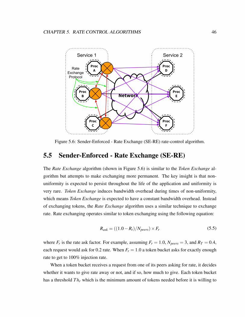
CHAPTER 5. RATE CONTROL ALGORITHMS 46
ProcC
ProcB
ProcA
ProcE
ProcF
ProcD
Service 1 Service 2
Network
Rate Exchange Protocol
Figure 5.6: Sender-Enforced - Rate Exchange (SE-RE) rate-control algorithm.
5.5 Sender-Enforced - Rate Exchange (SE-RE)
The Rate Exchange algorithm (shown in Figure 5.6) is similar to the Token Exchange al-
gorithm but attempts to make exchanging more permanent. The key insight is that non-
uniformity is expected to persist throughout the life of the application and uniformity is
very rare. Token Exchange induces bandwidth overhead during times of non-uniformity,
which means Token Exchange is expected to have a constant bandwidth overhead. Instead
of exchanging tokens, the Rate Exchange algorithm uses a similar technique to exchange
rate. Rate exchanging operates similar to token exchanging using the following equation:
Rask = ((1.0−Rt)/Npeers)×Fr (5.5)
where Fr is the rate ask factor. For example, assuming Fr = 1.0, Npeers = 3, and RT = 0.4,
each request would ask for 0.2 rate. When Fr = 1.0 a token bucket asks for exactly enough
rate to get to 100% injection rate.
When a token bucket receives a request from one of its peers asking for rate, it decides
whether it wants to give rate away or not, and if so, how much to give. Each token bucket
has a threshold T hr which is the minimum amount of tokens needed before it is willing to

CHAPTER 5. RATE CONTROL ALGORITHMS 47
give away any of its rate. If this threshold is exceeded, it is willing to give away some of its
rate based on a factor Fmr, where 0.0 < Fmr < 1.0. It gives rate according to the following
equation:
Rgive = min(Rask,Rt ×Fmr)
Rt = Rt −Rgive
(5.6)
After rate is given away, the token bucket fills at the new rate Rt , which is now slower than
is was prior to the request. When rate is retrieved from peers, the token bucket fills at a new
faster rate.
This algorithm provides correct behaviour and also has zero overhead if the processes
stay within their allotted rate. During times of non-uniformity the amount of bandwidth
overhead is proportional to the derivative of the rates. In other words, exchanging rates
allows the algorithm to adapt to non-uniformity by putting the rate where it needs to go.
Bandwidth overhead is only incurred during times of change. Latency overhead might be
incurred if the algorithm isn’t able to adapt fast enough to the rate of change. Receiving
additional rate from a peer doesn’t immediately allow blocked packets to proceed. They
must still wait until the proper number of tokens have been generated.
5.6 Sender-Enforced - Token and Rate Exchange (SE-TRE)
The Token and Rate Exchange algorithm (shown in Figure 5.7) is simply the combination
of the Token Exchange algorithm and the Rate Exchange algorithm. Each exchange request
asks for tokens and/or rate. Similarly, responses can contain tokens and/or rate. The two
exchange protocols remain logically independent, but use the same network requests and
responses. The insight into the usefulness of this algorithm is that token exchange makes
the right short term decision and rate exchange makes the right long term decision. This
hybrid algorithm yields the fast recovery of token exchanging and the dynamic non-uniform
adaptation of rate exchanging.
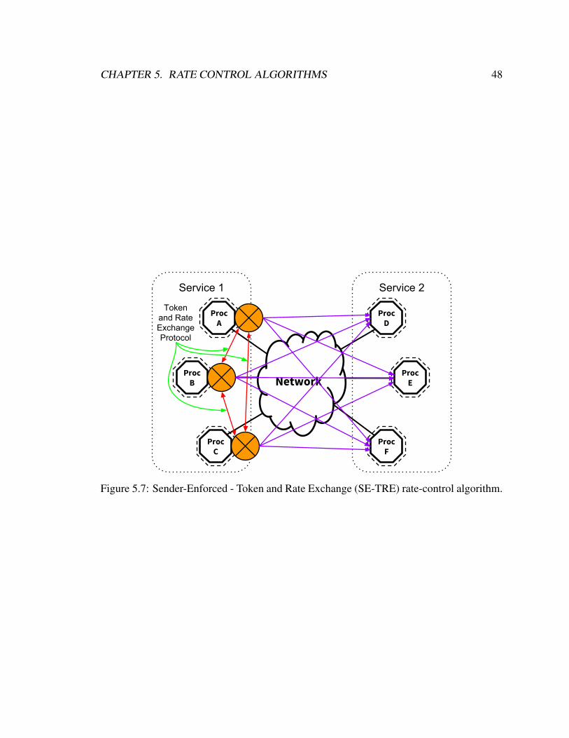
CHAPTER 5. RATE CONTROL ALGORITHMS 48
ProcC
ProcB
ProcA
ProcE
ProcF
ProcD
Service 1 Service 2
Network
Tokenand Rate Exchange Protocol
Figure 5.7: Sender-Enforced - Token and Rate Exchange (SE-TRE) rate-control algorithm.

Chapter 6
Network Management Unit
The workhorse of Sikker is a device called the Network Management Unit (NMU). This
chapter describes the architecture and functionality of the NMU. The NMU provides each
process with high-performance network access while implementing the Sikker security and
isolation model, described in Chapter 4. The name Network Management Unit is used to
resemble the name of the Memory Management Unit (MMU) used in all modern CPU
architectures. MMUs are hardware devices that sit between the processor and its corre-
sponding memory system in effort to implement efficient process-level isolation. MMUs
are governed by the host operating system using tables that hold mappings between process
identifiers and their memory-oriented permissions. In a similar vein, the NMU sits between
a host and the network. It is a hardware device that provides efficient service-level security
and isolation on the network. It is governed by the network operating system and contains
tables that hold mappings between services and their network-oriented permissions.
6.1 Architecture
This section describes the architecture of the NMU which is a new network interface con-
troller (NIC). As the entry point to the network (shown in Figure 6.1), the NMU is able
to enforce access control at the sender for every network transaction. A high-level archi-
tectural diagram of the NMU is shown in Figure 6.2 which shows that the NMU is an
extension to the standard NIC architecture with the following requirements:
49
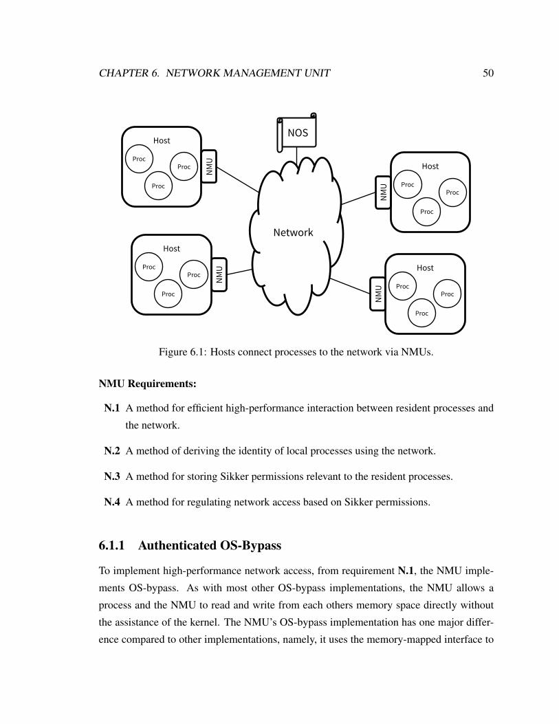
CHAPTER 6. NETWORK MANAGEMENT UNIT 50
Host
Host
Host
Host
Network
NOS
NMU
NMU
NMU
NMU
Proc
Proc
Proc
ProcProc
Proc Proc
Proc
Proc
Proc
ProcProc
Figure 6.1: Hosts connect processes to the network via NMUs.
NMU Requirements:
N.1 A method for efficient high-performance interaction between resident processes and
the network.
N.2 A method of deriving the identity of local processes using the network.
N.3 A method for storing Sikker permissions relevant to the resident processes.
N.4 A method for regulating network access based on Sikker permissions.
6.1.1 Authenticated OS-Bypass
To implement high-performance network access, from requirement N.1, the NMU imple-
ments OS-bypass. As with most other OS-bypass implementations, the NMU allows a
process and the NMU to read and write from each others memory space directly without
the assistance of the kernel. The NMU’s OS-bypass implementation has one major differ-
ence compared to other implementations, namely, it uses the memory-mapped interface to

CHAPTER 6. NETWORK MANAGEMENT UNIT 51
To NetTo CPUProcessor
Interconnect Controller
Network Access
Controller
Security Logic
HashMap Controller
Dynamic Memory Allocator
Memory System
Figure 6.2: The NMU architectural diagram.
derive the identity of a communicating process, which fulfills requirement N.2. This pro-
cess is shown in Figure 6.3. The NMU contains many virtual register sets, upon which, the
various processes are able to interact with the NMU. This corresponds to a large physical
address space mapped to the NMU. When a new networked process is started, the NMU
gives the host’s operating system the base address of the register set that the process will
use. The NMU contains an internal table that maps register set addresses to process iden-
tities, in terms of service ID and process ID. After the process is started, the register set is
mapped into the process’s address space via the memory management unit (MMU) and the
process is only able to use this register set for interaction with the NMU. The process never
tells the NMU its identity, instead, the NMU derives its identity from the memory address
used for communication with the NMU.

CHAPTER 6. NETWORK MANAGEMENT UNIT 52
NMU
0x00 = Svc:C Proc:7
0x01
0x02 = Svc:A Proc:0
0x03 = Svc:B Proc:4
0x04 = Svc:A Proc:3
0x05
0x06
0x07
Svc:A Proc:0
0x12340000
Svc:C Proc:7
0x12340000
Svc:A Proc:3
0x12340000
Svc:B Proc:4
0x12340000
MMU
0xC0002000
0xC0000000
0xC0004000
0xC0003000
VirtualAddresses
PhysicalAddresses
“LocalIndex”
Figure 6.3: The interaction between 4 process, the MMU, and the NMU. The NMU mapsvirtual register set addresses to Sikker’s high-level service-oriented process identifiers.

CHAPTER 6. NETWORK MANAGEMENT UNIT 53
IndexMap: (LocalService, LocalProcess) → LocalIndex
InfoMap: LocalIndex → (LocalService, LocalProcess, OtpNextKey,
PermissionMap: RemoteService → (ProcessMap,DomainSet, RateFSM)
ProcessMap: RemoteProcess → Address
DomainSet: RemoteDomain
OtpMap: OtpKey → (RequesterService, RequesterProcess,
PermissionMap,OtpMap,PeerSet)
RecipientService, RecipientProcess,RecipientDomain, RecipientAddress)
PeerSet: PeerAddress
Figure 6.4: The NMU’s internal nested hash maps data structures.
6.1.2 Nested Hash Map Accelerator
The internal data structures of the NMU have been crafted such that all variable sized data
is represented as nested hash maps1. Furthermore, the hash mappings and value placements
have been optimized to keep the hash maps as small as possible in effort to produce pre-
dictably low search times. The elements of the NMU’s internal data structures are listed in
nested form in Figure 6.4. These data structures are the NMU’s fulfillment of requirement
N.3 and comprise all the information needed for the resident processes to communicate
on the network. Because the NMU is governed by the NOS and not the host’s operating
system, the NMU’s memory subsystem is inaccessible by the host’s operating system2.
To implement the NMU’s internal data structures efficiently, the NMU architecture
has been designed as a data structure accelerator specifically for searching and managing
nested hash maps. As shown in Figure 6.2, the top-level architecture of the NMU consists
of three main elements above that of a standard NIC architecture: security logic, hash
map controller, and dynamic memory allocator. The combination of these logic blocks
facilitates the management of its internal data structures, the nested hash maps.
Attached to the memory system of the NMU is the dynamic memory allocator which
1Hash sets are considered the same as hash maps. A hash set is simply a hash map with a zero sized value.2It is possible to use the same memory system as the host processor if the NMU uses digital signatures to
verify that the information has not been tampered with.

CHAPTER 6. NETWORK MANAGEMENT UNIT 54
is a hardware implementation of a coalescing segregated fit free list allocator. This allo-
cator design has a good performance to memory utilization ratio across a wide variety of
access patterns [54]. Furthermore, the allocator is not in the critical path of the NMU’s
operation as dynamic memory allocation is only performed when the hash mappings are
modified. The allocator allows both the security logic and the hash map controller to cre-
ate, resize, and free dynamically sized blocks of memory. The hash map controller is a
hardware implementation of a linear probed open addressing (a.k.a. closed hashed) [55]
hash map controller. This particular hash map controller is used because it is extremely
cache friendly. It connects to the dynamic memory allocator and directly to the memory
system. Since the hash map controller handles all hash map operations, the security logic
simply issues a set of operations for each NMU function.
6.1.3 Permissions Enforcement
The NMU’s task is to efficiently check the permissions of every outgoing message before
it enters the network. For each potential message being sent on the network, the security
logic issues commands to the hash map controller, which traverses the nested data struc-
tures to ensure that proper permissions exist. If proper permissions do exist, the security
logic translates the virtual service-oriented network address, consisting of a destination ser-
vice, process, and domain, into a physical network address directly from the entries in the
hash maps. The message is then given to the network access controller to be sent on the
network. When proper permissions do not exist, the security logic rejects transmission of
the message and flags the process with an error code in its corresponding register set. This
functionality fulfills requirement N.4.
6.1.4 Management
The NOS manages every NMU in the system using an in-band management protocol which
gives the NOS the ability to send messages over the network directly to the NMUs. The
management protocol allows the NOS to modify the contents of the NMU’s internal data
structures explicitly giving the NOS control over the permissions that are placed within
each NMU.
CHAPTER 6. NETWORK MANAGEMENT UNIT 55
The NMU is able to distinguish control messages from the NOS with explicit authenti-
cation as the service ID of the NOS uses a reserved value. Before a new networked process
is started on a host, the NOS configures the NMU with all the permissions needed by that
process. Similarly, the NOS is also responsible for removing the permissions of a process
when the process ends.
6.2 Operation
This section walks through the operations the NMU performs and its traversal and manage-
ment of the data structures shown in Figure 6.4. “Local” variables refer to entities resident
on the NMU and “Remote” variables refer to entities that exist on other NMUs. It is possi-
ble to send messages between processes resident on the same NMU, however, the “Local”
and “Remote” distinctions will still be used. When using OTPs, the process that generates
the OTP is defined as the requester, the process that receives the OTP as the responder, and
the process that receives the message that was sent using the OTP as the recipient. Thus, the
requester sends an OTP and request message to the responder and the responder uses the
OTP to send a response message to the recipient. For two-way request-response protocols,
the requester and recipient are the same.
6.2.1 Send
To initiate a standard message send operation, the source process gives the NMU the
RemoteService, RemoteProcess, and RemoteDomain of the destination. The NMU de-
rives the sender’s LocalIndex which is a simple bit selection from the physical memory
address used by the process to communicate with the NMU. Next, the LocalIndex is used
as the key for an InfoMap lookup which yields, among other things, the PermissionMap.
The NMU then uses the RemoteService to perform a PermissionMap lookup which
yields the ProcessMap and DomainSet corresponding to the RemoteService. The NMU
now checks that the RemoteProcess exists within the ProcessMap and the RemoteDomain
within the DomainSet. If both lookups are successful, the Address that was returned by

CHAPTER 6. NETWORK MANAGEMENT UNIT 56
the ProcessMap lookup is used as the destination physical network address of the mes-
sage. The message header will contain LocalService and LocalProcess as the mes-
sage’s source and the RemoteService, RemoteProcess, and RemoteDomain as the mes-
sage’s destination. If any lookup during this procedure fails, the NMU will not send the
message and will set an error flag in the process’s register set.
6.2.2 Receive
When the destination NMU receives the message the destination service, process, and do-
main have now become the LocalService, LocalProcess, and LocalDomain. Using the
LocalService and LocalProcess, the NMU performs an IndexMap lookup which yields
the corresponding process’s LocalIndex and tells the NMU which register set the message
should be placed in.
6.2.3 Send with OTP
When the requester desires to generate and send a message with an attached OTP, on top
of specifying the responder as the destination of the message, it must also specify the
recipient. The NMU uses the same permission check procedure as in Section 6.2.1 except
now it performs two PermissionMap, ProcessMap, DomainSet lookup sequences, one
for the responder and one for the recipient. Upon successful lookups, the NMU sends the
message just like it did in Section 6.2.1 except that the message header also contains the
recipient’s information as the OTP.
6.2.4 Receive with OTP
When the responder’s NMU receives the message containing the OTP it starts as usual by
performing an IndexMap lookup yielding the LocalIndex. It also performs an InfoMap
lookup to retrieve the OtpNextKey and OtpMap. The OtpNextKey and the received mes-
sage are now placed in the corresponding process’s register set. The NMU performs a hash
map insertion into the OtpMap which maps the OtpNextKey to the OTP information given
in the message. The NMU then advances OtpNextKey to the next key and writes it into the

CHAPTER 6. NETWORK MANAGEMENT UNIT 57
proper memory location.
6.2.5 Send using OTP
When the responder is ready to send the response message using the OTP, it does not specify
the destination in terms of service, process, and domain. Instead, the process gives the
NMU the OtpKey it was given during the receive operation. The NMU uses the process’s
corresponding LocalIndex to retrieve its OtpMap from the InfoMap. The NMU then uses
the OtpKey to perform an OtpMap removal operation to retrieve and remove the OTP, which
consists of the requester’s information as well as the recipient’s information. The recipient’s
information is used as the message destination and the requester’s information is also added
to the message header so the recipient knows where the message sequence originated from.
Since the OTP was removed from the OtpMap during this procedure, the OTP cannot be
used again.
6.2.6 Rate Control
After a message send operation passes access-control checks, it then proceeds to the rate-
control mechanism. If the message is being sent with an OTP or if a rate limit is not
specified for the destination service, the message will bypass the rate-control mechanism
and will be sent on the network immediately. During the send operation, the source pro-
cess’s PeerSet is pulled from the InfoMap as well as the RateFSM for the corresponding
destination service. The PeerSet contains the addresses of a set of other processes within
the source service. When the rate-control algorithm needs to exchange control information
with other processes in the service, it uses the PeerSet to find peer process addresses.
The RateFSM holds all the values needed to implement the distributed rate-control algo-
rithm being used. Chapter 5 covered a set of candidate algorithms in detail and Chapter 8
evaluates these algorithms for use in the NMU.

Chapter 7
Access Control Evaluation
This chapter provides an evaluation of the access-control functionality defined by Sikker
as implemented by the NMU. Since the NMU can be viewed as an extension to the stan-
dard NIC architecture, its performance is quantified by measuring the additional overhead
incurred by performing its operations in terms of latency and bandwidth. Since the NMU
performs at least one permission check1 for every message being sent on the network, it is
extremely critical that this is completed in a timely manner without limiting bandwidth and
without inducing CPU overhead.
7.1 Methodology
This section describes the methodology used to explore potential NMU configurations as
well as the creation of synthetic workloads that stress test the NMU’s permissions checking
procedure.
7.1.1 Simulation
The logic of the NMU can be attached to any memory system and the performance of the
NMU widely depends on the structure and size of the memory system chosen. To explore
1As mentioned in Section 4.4, the NMU performs a single permission check for regular messages and twopermission checks for messages that also generate an OTP.
58

CHAPTER 7. ACCESS CONTROL EVALUATION 59
the design space of the NMU, a custom simulator, called SikkerSim, was developed and
used to measure the NMU’s performance while performing permissions checks. At the
top level of SikkerSim is an implementation of the core logic of a NOS that manages the
permissions of all the NMUs on a network. It does this by creating a permission connec-
tivity graph as shown in Figure 4.4 and connects a simulated NMU on each simulated host.
For each simulated NMU, SikkerSim models the internal logic elements of the NMU as
well as various memory system architectures under design consideration. SikkerSim can
be used to model potential NMU memory systems spanning from single SRAMs to multi-
stage cache hierarchies connected to DRAM. CACTI 6.5 (32nm process technology) [56]
and DRAMSim2 (DDR3 SDRAM) [57] are used in connection with SikkerSim to produce
accurate timing results for each case.
Even though Section 4.8 shows that SACLs allow endpoints to use pure SRAM stor-
age, the modeling and simulations presented in this chapter model the main memory as
off-chip DRAM to remain agnostic to system size and connectivity density. For the sake
of performance analysis, an average memory system design was chosen that yields high
performance while not incurring excessive cost. This design attaches the NMU logic to
a memory system containing two levels of cache and a DRAM main memory. The first
cache level (L1) is an 8-way set associative 32 kiB cache. The second cache level (L2) is a
16-way set associative 4 MiB cache. Unlike standard microprocessor cache hierarchies, the
NMU operates directly on physical memory addresses and considers all memory as “data”.
The NMU doesn’t need an MMU, TLB, or instruction cache, thus, the NMU’s physical
interface to the L1 cache is fast and lightweight.
7.1.2 Permission Access Patterns
The data structures of the NMU present abundant spatial locality to the memory system,
and depending on the permission access pattern, significant temporal locality can also exist.
SikkerSim contains a configurable synthetic permission access pattern that is placed on
each simulated NMU. For every permissions check, the access pattern selects a source
process as the sender and a destination process as the receiver. The access pattern also
selects a domain to be used that is defined within the destination service.

CHAPTER 7. ACCESS CONTROL EVALUATION 60
The worst-case access pattern is a uniform random selection across the source and
destination possibilities. In this pattern, each permissions check randomly selects a resident
process as the source, then randomly selects the destination service, process, and domain
from the corresponding source service’s permissions. This pattern exhibits no temporal
locality in the NMU’s memory system.
The best case access pattern is repeatedly choosing the same source and destination.
This pattern exhibits full temporal locality in the memory system. While this pattern is
unrealistic for long durations, it is realistic for very short durations. A slight variant of
this pattern would be repeatedly accessing the same destination service, while switching
destination process and/or domain. Similarly, the same source process might be repeatedly
accessing the network but choosing a new destination each time.
Since both the worst and best case access patterns are somewhat realistic, the synthetic
permission access pattern in SikkerSim was designed to reflect two common attributes that
control temporal locality in a realistic way.
Repeated Access - The first attribute configures the amount of repeatability at each step
of the selection process for the source and destination. There are several aspects that make
this realistic in practice. For instance, it is common for a process using the network to inter-
act several times with the network before another process has the chance to or chooses to.
This can be caused by CPU thread scheduling or application-level network bursting. Also,
it is common for a process to send multiple back-to-back messages to the same destination
service or even the same destination service and process and/or service and domain. The
result is a higher level of temporal locality simply due to repeated accesses in a particular
selection group.
Hot Spots - The second attribute configures the selection distribution when the syn-
thetic permission access pattern chooses a new source and destination. This is used to
model hot spots in network traffic. For instance, an high-throughput application using an
SQL database will often use an in-memory caching service to reduce the load on the SQL
database. For this example, the in-memory cache is a hot spot as it is accessed with higher
frequency than the SQL database. To model this behavior, the selection process is allowed
to choose using a uniform random distribution or a Gaussian random distribution. The uni-
form random distribution models network traffic that is irregular and unpredictable while

CHAPTER 7. ACCESS CONTROL EVALUATION 61
the Gaussian random distribution models network traffic that contains hot spots both in
terms of the source and destination with all its components.
Using these controllable attributes, SikkerSim’s synthetic permission access pattern was
used to create four access patterns that are used to benchmark the performance of the NMU.
They are as follows:
• Uniform Random (UR): All selections are from a uniform random distribution.
• Uniform Repeated Random (URR): Same as UR, except that portions of the selec-
tion are re-used a configurable number of times.
• Gaussian Random (GR): All selections are from a Gaussian random distribution.
• Gaussian Repeated Random (GRR): Same as GR, except that portions of the se-
lection are re-used a configurable number of times.
7.2 Results
This section presents the performance results of the NMU in terms of latency and band-
width overhead. SikkerSim was used to simulate systems spanning from a few thousand
hosts up to systems of well over 100,000 hosts. All simulations use the connectivity model
presented in Section 4.7 to represent the service-oriented connectivity density in the sys-
tem.
7.2.1 Latency
This section analyzes the latency incurred in the NMU for checking permissions. Figure
7.1 shows the mean, 99th percentile, and 99.99th percentile latency response of permission
checks for each of the four permission access patterns described in Section 7.1.2. As ex-
pected, the UR and GRR patterns represent the worst and best patterns, however, the mean
of the UR pattern is only up to 25% worse than the GRR pattern and both curves flatten out
by 32,768 hosts. Even under extreme conditions, the NMU adds negligible latency over-
head to network transactions. On a large system with over 2 million networked processes
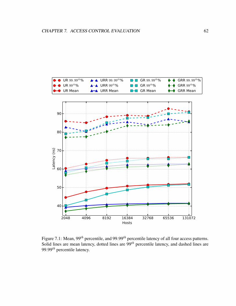
CHAPTER 7. ACCESS CONTROL EVALUATION 62
2048 4096 8192 16384 32768 65536 131072Hosts
40
50
60
70
80
90
Late
ncy
(ns)
UR 99. 99th%
UR 99th%
UR Mean
URR 99. 99th%
URR 99th%
URR Mean
GR 99. 99th%
GR 99th%
GR Mean
GRR 99. 99th%
GRR 99th%
GRR Mean
Figure 7.1: Mean, 99th percentile, and 99.99th percentile latency of all four access patterns.Solid lines are mean latency, dotted lines are 99th percentile latency, and dashed lines are99.99th percentile latency.

CHAPTER 7. ACCESS CONTROL EVALUATION 63
(131,072 hosts), the mean latency of a realistic access pattern (GRR) is only 41 ns and the
99.99th percentile latency of the worst-case access pattern (UR) is only 91 ns. Relative
to the standard permissions checking process, using OTPs incurs the same latency over-
head with negligible differences. The main difference is that generating an OTP during a
message send operation requires two permission checks, however, these can run in parallel.
7.2.2 Bandwidth
While predictably low latency is an important metric of performance, bandwidth is also
an important metric in high-performance computing. Table 7.1 shows the throughput of
a single NMU logic engine in terms of millions of permission checks per second (Mcps).
The ability to translate checks per second to bytes per second requires an understanding
of the average message size within the system. This value varies widely depending on the
applications running within the system. For example, a study of Microsoft’s data centers
shows the average packet size to be 850 bytes [58] while a study of Facebook’s data centers
shows the average packet size to be 200 bytes [59]. Table 7.1 shows the translation to
bandwidth for both of these values. This shows that a single NMU logic engine on a very
large cluster (131,072 hosts) with a realistic permission access pattern (GRR) can process
over 24 million permission checks per second. The worst case access pattern only degrades
the throughput by 21%.
UR GRRPermission checks per second 19.23 Mcps 24.39 McpsBandwidth (850 byte packets) 130.77 Gbps 165.85 GbpsBandwidth (200 byte packets) 30.77 Gbps 39.02 Gbps
Table 7.1: Throughput performance of a single NMU logic engine. Mcps is million per-mission checks per second. Gbps is gigabits per second.
The amount of bandwidth induced by the NMU on its main memory is very small. The
logic engine of the NMU is designed with simplicity to have only a single outstanding
memory request. Due to the NMU’s efficient organization of its nested data structures and
the performance attributes of well-tuned open addressed hash maps, each permission check
averages only a single main memory operation. Since each operation transfers an entire

CHAPTER 7. ACCESS CONTROL EVALUATION 64
cache line of 64 bytes, when the NMU is running at 24.39 Mcps, the bandwidth induced on
the main memory is approximately 1.756 GB/s. In comparison, a typical DRAM memory
channel is capable of approximately 25 GB/s.
Because the complexity of the NMU is abstracted away by its internal data structures,
the complexity of adding multiple logic engines to the NMU is fairly trivial. Furthermore,
the majority of the operations performed in the NMU are read-only operations, which are
highly parallelizable. For the operations that require writes (i.e., OTPs), distributing data
structure ownership across multiple engines and using hash-based message steering to the
corresponding engine allows near lock-free parallelization. With relatively little effort,
an NMU can be built with many logic engines. Multiple logic engines don’t impose a
bandwidth bottleneck on the NMU’s main memory as it would take over 14 logic engines to
saturate a single 25 GB/s memory channel and there’s no reason multiple memory channels
couldn’t be employed. Based on the results in Table 7.1 and degrading performance by 10%
to account for potential lock contention, an NMU with 8 logic engines is able to process
138 - 176 million permissions checks per second which yields over 1 Tbps for Microsoft
packet sizes. This only requires 14 GB/s of DRAM memory bandwidth.
7.2.3 Security
The NMU implements all the security and isolation features of Sikker as discussed in
Chapter 4. This includes source and destination authentication, virtual-to-physical network
address translation, sender-enforced service-oriented permission checks, and permissions
management.
The Sikker application model uses individual endpoint machines to host the processes
of the various services (hence the name host). As such, Sikker relies on the host’s operating
system to provide process-level isolation between the processes resident on that host. In
general, Sikker assumes that the various host operating systems within the network are
unreliable. For this reason, the NMU was designed to be explicitly controlled by the NOS
rather than individual host operating systems. For the same reason, the NMU has its own
memory system that is inaccessible by the host’s operating system.
In the event that a host’s operating system is exploited by a resident process, the process

CHAPTER 7. ACCESS CONTROL EVALUATION 65
Host
Host
Host
Host
Network
NOS
P
P
NMU
P
P
P
NMU
P
P
P
NMU P
P
P
NMU
Figure 7.2: The NMU contains an exploited host to the permissions that exists withinthat NMU. Red lines show potentially affected permissions. Green lines show un-affectedpermissions.
might be able to assume any of the permissions that have been given to all processes on
that host, as shown in Figure 7.2. This is a large improvement over current systems that
utilize the host operating systems for security (e.g., hypervisor-based security and isola-
tion). In those systems, an exploited operating system might be given access to anything
in the entire network, not just the permissions resident on that host. In Sikker, if a host’s
operating system cannot be deemed reliable enough provide process-level isolation, it is
recommended to co-locate processes only where an attack would not prove detrimental if
one resident process gained access to another resident process’s permissions. In many sce-
narios this is already the case due to the difficulty of providing machine-level performance
isolation.

CHAPTER 7. ACCESS CONTROL EVALUATION 66
7.3 Summary
As an extension to the common NIC architecture, the NMU can only increase the overhead
of network transactions relative to a system without any security and isolation features.
However, due to Sikker’s service-oriented permission scheme and the NMU’s efficient im-
plementation, the overhead of the NMU is negligible. If all round trip network transactions
took only 2 µs, the NMU imposed overhead would only increase latency by 4%. More re-
alistic round trips of 10 µs that include potential queuing delays and/or endpoint processing
time brings this overhead down to 0.8%. Furthermore, operations that induce this negligible
overhead cover the entire access-control needs of the application.
Today’s security and isolation schemes impose at minimum many tens of microseconds
of latency overhead and high CPU overhead. These systems are unable to completely sat-
isfy the security and isolation requirements of modern large-scale applications thus forcing
the applications to attempt to solve these issues themselves. In contrast, Sikker and the
NMU provide a secure and efficient computing environment with essentially no overhead.

Chapter 8
Rate Control Evaluation
This chapter evaluates the six rate-control algorithms presented in Chapter 5 for use in
Sikker. While any of the algorithms could be implemented in the NMU, it is desirable to
minimize the amount of overhead incurred by the rate-control feature specified by Sikker’s
service-oriented application model. For these algorithms, overhead is measured in terms of
additional network latency incurred as well as any additional bandwidth consumed beyond
the original payloads being sent from the source service to the destination service.
8.1 Methodology
A custom simulator, called RateSim, was developed to explore the proposed distributed
rate-control algorithms while simulating the interactions of services on a network. The
simulator models many processes, each being a part of a service, and the network. The net-
work modeling allows each process to send at 100% injection rate bandwidth and receive
with infinite bandwidth. This type of optimistic network modeling isolates any network
congestion from congestion that could be caused by a rate-control algorithm under investi-
gation. Even though the modeled processes can receive messages with infinite bandwidth,
serialization latency is modeled as each process can only send at line rate and queuing
congestion occurs when a process has more than one packet in its queue to send.
The algorithm proposed in this dissertation is designed to make high-performance inter-
connection networks usable for service-oriented applications as ubiquitously deployed in
67

CHAPTER 8. RATE CONTROL EVALUATION 68
data centers and cloud computing environments. As such, the methodology for evaluating
distributed rate-control algorithms is based around the performance of high-performance
computing systems. For all simulations, the link bandwidth of each process is 100 Gbps
and the network latency is 500 ns, similar to a modern supercomputer [11]. The simulation
assumes a 1 GHz clock cycle which yields a phit size of 100 bits. The minimum data packet
size is 5 phits (≈64 bytes) and the maximum size is 82 phits (≈1024 bytes).
Each process within the source service has a designated rate at which it desires to send
packets to the destination service. For each packet sent, the simulation generates a ran-
domly sized packet between 5 and 82 phits and randomly selects the destination process
within the destination service. All latencies are measured from the time a packet was cre-
ated to the time in which the process within the destination service receives the packet
entirely. Bandwidth overhead is measured as the amount of bandwidth being received on
the network by entities other than the destination processes. For the algorithms presented
in Chapter 5, this is the source processes and relay devices.
For all simulations, the source service contains 1000 processes and the destination ser-
vice contains 750 processes. The rate limit is set to an aggregate rate of 500 phits per cycle,
which equates to an average of 50% injection rate for each source process. The traffic pat-
tern used for simulation, shown in Figure 8.1, is a benign traffic pattern as the aggregate
rate is always 40% or 400 phits per cycle. It is meant to stress test the various corner cases
of the presented rate-control algorithms. On cycle 1 all processes in the source service start
sending at 40%. On cycle 10,000 senders 1 through 500 increase their rate to 80% while
senders 501 through 1000 turn off. During this period the aggregate rate is still 40%. On
cycle 50,000 the two groups of senders swap configurations with senders 1 through 500
turning off and senders 501 through 1000 sending at 80%. On cycle 90,000 all senders
again send at 40% rate until cycle 130,000 when the simulation ends.
The time periods from cycle 10,000 to 50,000, 50,000 to 90,000, and 90,000 to 130,000
will be referred to as “period 1”, “period 2”, and “period 3”, respectively. The interval
between all periods is 40,000 cycles, or 40 µs. While the frequency at which many appli-
cations change usage behaviour is a lower than this, the 40 µs interval is used as a harsh
stress-test for the rate-control algorithms under investigation.
When utilizing token buckets for rate control, it is advantageous to minimize the size of

CHAPTER 8. RATE CONTROL EVALUATION 69
Figure 8.1: Stress testing traffic pattern for rate-control simulation.
the token buckets used. The size of the token bucket represents the largest burst size that can
be sent to the destination. Because this work explores distributed rate-control algorithms
that utilize multiple token buckets, the maximum aggregate burst size Tbs is
Tbs = Sb ×Ntb (8.1)
where Ntb is the number of token buckets being utilized by an algorithm. The results
in Section 8.2 represent simulations using token buckets of size 2000. An algorithm using
1000 token buckets each with 2000 token slots can yield up to 2 million outstanding tokens.
If each token represents 1 phit (100 bits) and the clock frequency is 1 GHz, each token
bucket can hold up to 25k bytes worth of tokens which it could be sent at full speed (100
Gbps) for 2 µs. If all 1000 token buckets simultaneously sent a maximum size burst the
aggregate size would be 25M bytes.
The large number of parameters in the algorithms presents a challenge in representing
the optimal configuration for each algorithm. To tackle the issue, a massively parallel
simulation was performed to simulate nearly all practical settings of each algorithm. The

CHAPTER 8. RATE CONTROL EVALUATION 70
results in Section 8.2 evaluate the configurations that yield the highest performance for each
algorithm assuming system designers have properly tuned the algorithms to their system.
The discussion in Section 8.3 gives insight to the values of some of the parameters.
When utilizing token buckets for rate control, many parameters express a trade-off be-
tween bandwidth and latency where a more aggressive setting can lower latency by using
more bandwidth. To find the optimal parameter settings for a set of simulation runs, each
simulation result is assigned a penalty score based on a weighted sum of the bandwidth
overhead and latency overhead. In the penalty calculation, latency overhead is defined as
the worse case 99.99th percentile across the 3 time periods. Bandwidth overhead similarly
takes the worse case of the 3 time periods except the 3rd time period has a 2x weight. The
reason for this is that during this time period all senders are sending at the same rate, thus,
in theory there should be no extra bandwidth needed. The latency overhead and bandwidth
overhead are summed after the bandwidth overhead is weighted by 75x. This effectively
states that 1 phit per cycle (or 100 Gbps) of bandwidth is considered equal in cost to 75 ns
of 99.99th percentile latency. This coefficient is subjective and system designers should
choose its value carefully based on their specific network constraints. For a set of simula-
tion runs, the penalty of each result is computed and the simulation run that produces the
lowest penalty is deemed optimal.
8.2 Results
Figure 8.2 shows the bandwidth usage of the six rate-control algorithms. All algorithms
besides the SE-FA algorithm are able to supply the senders with enough bandwidth. At
the start of each time period when the application changes its behavior there is a small
disruption in the smooth aggregate bandwidth usage. This is a result of some senders
starting their transactions while the queues of their peers are still draining.
During times of non-uniform use among the senders, the SE-FA algorithm is unable to
provide enough bandwidth and consequently the latency is effectively infinite. This infi-
nite latency can be seen in Figure 8.3 which shows a latency scatter plot for each of the
algorithms. As shown, the NE, SE-TE, and SE-TRE algorithms all yield good latency

CHAPTER 8. RATE CONTROL EVALUATION 71
(a) NE (b) RE (c) SE-FA
(d) SE-TE (e) SE-RE (f) SE-TRE
Figure 8.2: Bandwidth usage of the six rate-control algorithms. The yellow dashed lineshows the aggregate rate limit of 500 phits per cycle. The blue line shows bandwidthreceived by the receiving service. The red line shows bandwidth sent by sending service.The green line shows bandwidth received by sending service.

CHAPTER 8. RATE CONTROL EVALUATION 72
(a) NE (b) RE (c) SE-FA
(d) SE-TE (e) SE-RE (f) SE-TRE
Figure 8.3: End-to-end latency of the six rate-control algorithms.
responses. The minimum latency of the RE algorithm is twice as large as all other algo-
rithms (1000 ns vs. 500 ns) because each packet must traverse the network twice. For each
algorithm, Figure 8.4 shows a percentile plot of the worst-case latency across the 3 time
periods. Figures 8.3 and 8.4 show that the RE algorithm induces a significant amount of
queuing delay which severely effects its tail latency response. The SE-RE algorithm also
yields a very poor latency response in the second time period which is caused by the algo-
rithm adapting too slow to the harsh transition made by the senders abruptly changing their
rate usage by 80%. The senders are able to exchange the necessary rates but having the
right rate is only good in the long term as the senders still need to wait for the new rate to
generate tokens for the currently outstanding packets.
The bandwidth response, shown in Figure 8.5, shows that the NE and SE-FA algo-
rithms have zero bandwidth overhead as expected. The RE algorithm results in over 100%
bandwidth overhead because of the 2x network traversals and the extra protocol needed to
maintain the queues in the relays. As expected, the SE-TE algorithm has zero bandwidth
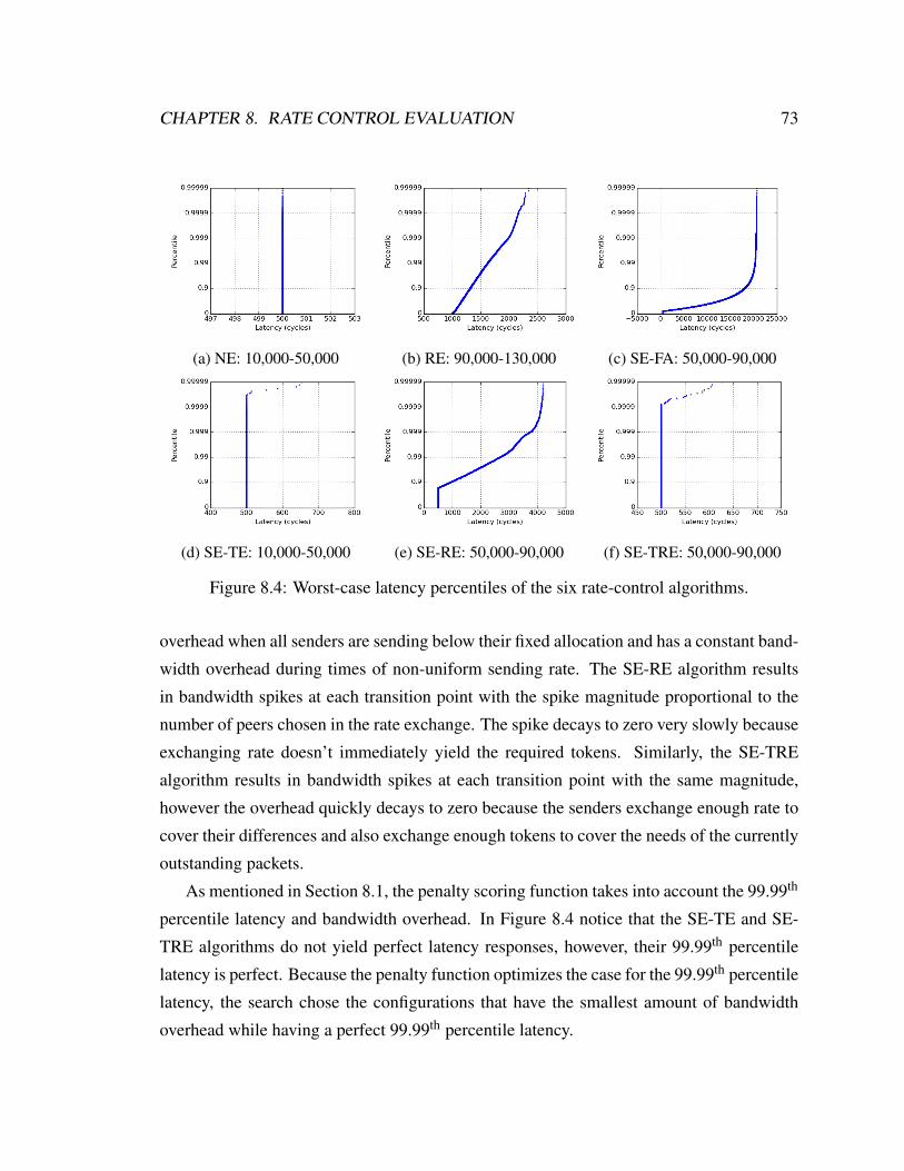
CHAPTER 8. RATE CONTROL EVALUATION 73
(a) NE: 10,000-50,000 (b) RE: 90,000-130,000 (c) SE-FA: 50,000-90,000
(d) SE-TE: 10,000-50,000 (e) SE-RE: 50,000-90,000 (f) SE-TRE: 50,000-90,000
Figure 8.4: Worst-case latency percentiles of the six rate-control algorithms.
overhead when all senders are sending below their fixed allocation and has a constant band-
width overhead during times of non-uniform sending rate. The SE-RE algorithm results
in bandwidth spikes at each transition point with the spike magnitude proportional to the
number of peers chosen in the rate exchange. The spike decays to zero very slowly because
exchanging rate doesn’t immediately yield the required tokens. Similarly, the SE-TRE
algorithm results in bandwidth spikes at each transition point with the same magnitude,
however the overhead quickly decays to zero because the senders exchange enough rate to
cover their differences and also exchange enough tokens to cover the needs of the currently
outstanding packets.
As mentioned in Section 8.1, the penalty scoring function takes into account the 99.99th
percentile latency and bandwidth overhead. In Figure 8.4 notice that the SE-TE and SE-
TRE algorithms do not yield perfect latency responses, however, their 99.99th percentile
latency is perfect. Because the penalty function optimizes the case for the 99.99th percentile
latency, the search chose the configurations that have the smallest amount of bandwidth
overhead while having a perfect 99.99th percentile latency.

CHAPTER 8. RATE CONTROL EVALUATION 74
(a) NE (b) RE (c) SE-FA
(d) SE-TE (e) SE-RE (f) SE-TRE
Figure 8.5: Bandwidth overhead of the six rate-control algorithms.
The aggregate results for the six rate-control algorithms are shown in Table 8.1. As
shown, of all algorithms that produce correct behavior the SE-TRE has the best results.
The second best algorithm is the SE-TE algorithm. The bandwidth overhead of the SE-TE
algorithm is constant and its value is proportional to the amount of non-uniformity among
the source processes. The bandwidth overhead of the SE-TRE algorithm is dependent on
the frequency at which the application changes its behaviour. Table 8.1 shows the results
for 25 kHz (or 40 µs intervals). If the frequency of transition happened to be 1 kHz (or
1 ms intervals), the SE-TE algorithm would still result in 262 Gbps of bandwidth over-
head, however the SE-TRE algorithm would produce approximately 6 Gbps of bandwidth
overhead.

CHAPTER 8. RATE CONTROL EVALUATION 75
99.99th% BandwidthAlgorithm Section Correct Latency Overhead
NE 5.1 No 500 ns 0 GbpsRE 5.2 Yes 2168 ns 41978 Gbps
SE-FA 5.3 Yes ∞ 0 GbpsSE-TE 5.4 Yes 500 ns 262 GbpsSE-RE 5.5 Yes 4143 ns 463 Gbps
SE-TRE 5.6 Yes 500 ns 142 Gbps
Table 8.1: Rate-control evaluation results of the six algorithms.
8.3 Discussion
The results in Section 8.2 were achieved using massive amounts of simulation to find the
optimal configurations of each algorithm. This section discusses the effects of some of the
dominant variables as they are varied.
8.3.1 Token Bucket Sizing
As discussed in Section 8.1, the sizing of token buckets creates a trade-off between the
efficiency and the strength of a rate-control algorithm. A smaller token bucket reduces the
amount of traffic that the source service can burst to the destination service. It is desirable
to have this be as small as possible. However, the token buckets need to be large enough
such that the rate-control algorithm can adapt to the changes in application behavior before
it runs out of resources and incurs high latency. The minimum size of the token bucket is
proportional to the network round trip between the peer token buckets. The simulations
presented in Section 8.2 used a token bucket of 2000 tokens (2000 phits or 25k bytes).
This represents 2 network round trips given the fixed 500 ns (500 cycles) unidirectional
network latency. This yields a result where the algorithm is able to serially ask 2 peer
token buckets for additional resources. It is important to allow serial requests because the
random selection process sometimes yields scenarios where none of the randomly selected
peers have excess resources. In this case, the token bucket needs to ask another set of peers
for resources before it runs out of tokens.
Figure 8.6 and Table 8.2 show the latency percentile and bandwidth overhead of the

CHAPTER 8. RATE CONTROL EVALUATION 76
(a) (b) (c)
(d) (e) (f)
Figure 8.6: A comparison of the SE-TRE algorithm implemented with different tokenbucket sizes. (a) and (d) use 1500 tokens, (b) and (e) use 2000 tokens, and (c) and (f)use 2500 tokens. (a), (b), and (c) show bandwidth overheads and (d), (e), and (f) showworst-case latency percentiles.
99.99th% Bandwidth MaximumToken Bucket Latency Overhead Burst Size
1500 1010 ns 159 Gbps 18.7M bytes2000 500 ns 142 Gbps 25M bytes2500 500 ns 140 Gbps 31M bytes
Table 8.2: SE-TRE performance when varying the token bucket size.

CHAPTER 8. RATE CONTROL EVALUATION 77
SE-TRE algorithm using a token bucket size of 1500, 2000, and 2500. The rest of the
parameters remain the same as configured for the simulations in Section 8.2. As shown,
larger token bucket implementations yield higher performance, both in terms of lower la-
tency and lower bandwidth overhead, however, the bandwidth overhead is not significantly
reduced. Using token buckets of size 1500 yields an individual burst size of 18.7k bytes
and a aggregate burst size from 1000 processes of 18.7M bytes. Using token buckets of
size 2500 yields an individual burst size of 31k bytes and a 1000 process aggregate burst
of 31M bytes. Given the increase in performance and the small increase of burst size, it is
most likely the best choice to find the smallest token bucket size that overcomes all latency
overheads for an expected workload. For the setup in these simulations, token buckets of
size 2500 perfectly overcome all latency overhead. Token buckets of size 2000 were cho-
sen for the analysis because it is the minimal amount of tokens that yields perfect 99.99th
percentile latency.
8.3.2 Greed and Generosity
When tuning the Sender-Enforced rate-control algorithms, the values for T hlow, Ft , Fr, T ht ,
T hr, and Fmr present several interesting trade-offs (see Table 5.1 for variable definitions).
From the perspective of an individual token bucket, these variable express when request-
ing additional resources from peers should begin, how many resources should be asked
for, when to give resources to requesting peers, and how many resources should be given.
The Token Exchange protocol is a short term optimization and the Rate Exchange proto-
col is a long term optimization. As such, optimal tuning of these independent protocols
exhibit much different behavior. From the many simulations performed during the search
for optimal settings, it was learned that exchanging tokens should be done generously. The
requester should start soon and the responder should give as many as possible. In contrast,
it was learned that exchanging rate should be done very cautiously. The requester should
still start early but the responder should be very careful not to give away any of its rate
unless it is sure it will not need it soon. Specifically, the SE-TRE algorithm optimized for
token buckets of size 2000 gives away tokens when its token bucket is only 35% full but
waits until it is 90% full before it gives away any of its rate.
CHAPTER 8. RATE CONTROL EVALUATION 78
8.4 Summary
This chapter has shown that service-oriented distributed rate control is feasible and can op-
erate with low overhead. The ability to achieve this efficiently relies on the service-oriented
programming model of Sikker. The Sender-Enforced Token and Rate Exchange (SE-TRE)
algorithm has been shown to provide extremely low latency and bandwidth overhead even
when put under pressure by constantly changing distributed applications. The high effi-
ciency of the SE-TRE algorithm empowers the use of token buckets of minimal size while
also having enough resources for efficient distributed rate control. This algorithm is im-
plemented as a reactionary state machine that only executes when a message is being sent.
When combined with efficient access control by the NMU, SE-TRE is able to provide a
secure and isolated computing environment for distributed applications incurring minimal
latency and bandwidth overhead and zero CPU overhead.

Chapter 9
Optimizations and Improvements
This chapter discusses several options for optimization and improvement for Sikker and/or
the NMU. None of these are required for Sikker to operate as designed, however they
pose potential productivity and/or performance gains under certain environments. As a
service-oriented computing model, Sikker can provide optimizations and improvements for
many bottlenecks related to expressing application-specific communication patterns both in
hardware and in software. A small subset of these issues is discussed in this chapter.
9.1 Contiguous Process Placement
The way in which the NOS (i.e., cluster coordinator) schedules services on the network
has the potential of providing Sikker with an extraordinary optimization opportunity. The
Sikker application model, as described in Section 4, defines the structure of a service to be
a set of processes and domains. Each process of a service gets placed at a specific location
on the network residing on a host. In efforts to remain agnostic to the underlying network
infrastructure, Sikker places no constraints on the physical network addressing scheme of
the network nor the placement of processes. The data structures in the NMU, as shown in
Figure 6.4, hold a unique address value for every destination process the source process has
been given access to.
79
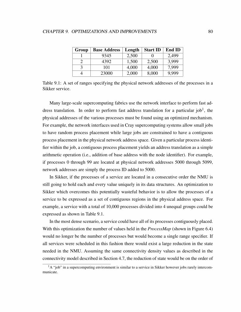
CHAPTER 9. OPTIMIZATIONS AND IMPROVEMENTS 80
Group Base Address Length Start ID End ID1 9345 2,500 0 2,4992 4392 1,500 2,500 3,9993 101 4,000 4,000 7,9994 23000 2,000 8,000 9,999
Table 9.1: A set of ranges specifying the physical network addresses of the processes in aSikker service.
Many large-scale supercomputing fabrics use the network interface to perform fast ad-
dress translation. In order to perform fast address translation for a particular job1, the
physical addresses of the various processes must be found using an optimized mechanism.
For example, the network interfaces used in Cray supercomputing systems allow small jobs
to have random process placement while large jobs are constrained to have a contiguous
process placement in the physical network address space. Given a particular process identi-
fier within the job, a contiguous process placement yields an address translation as a simple
arithmetic operation (i.e., addition of base address with the node identifier). For example,
if processes 0 through 99 are located at physical network addresses 5000 through 5099,
network addresses are simply the process ID added to 5000.
In Sikker, if the processes of a service are located in a consecutive order the NMU is
still going to hold each and every value uniquely in its data structures. An optimization to
Sikker which overcomes this potentially wasteful behavior is to allow the processes of a
service to be expressed as a set of contiguous regions in the physical address space. For
example, a service with a total of 10,000 processes divided into 4 unequal groups could be
expressed as shown in Table 9.1.
In the most dense scenario, a service could have all of its processes contiguously placed.
With this optimization the number of values held in the ProcessMap (shown in Figure 6.4)
would no longer be the number of processes but would become a single range specifier. If
all services were scheduled in this fashion there would exist a large reduction in the state
needed in the NMU. Assuming the same connectivity density values as described in the
connectivity model described in Section 4.7, the reduction of state would be on the order of
1A “job” in a supercomputing environment is similar to a service in Sikker however jobs rarely intercom-municate.
CHAPTER 9. OPTIMIZATIONS AND IMPROVEMENTS 81
2 to 3 orders of magnitude as the reduction is proportional to the number of processes per
service. In terms of NMU performance, this not only reduces the memory size requirements
but also significantly increases performance due to more data fitting in the cache. Scientific
computing environments often schedule jobs much larger than the services found within
data centers and cloud computing environments. This poses an even larger opportunity
of optimization for Sikker as the number of processes per service can be many tens of
thousands up to millions.
9.2 End-to-End Zero Copy
Zero copy is a technique that aims to send messages from one side of the network to another
without making unneeded copies while transferring data between the application and the
network interface [60, 61]. This technique was first introduced as a mechanism to remove
the copying the kernel performed while interacting between the application and the network
interface. Zero-copy was extended to work in OS-bypass environments such that the mes-
sage being sent or received could be directly pulled from or placed into the application’s
memory space without explicit copies being made in the network interface. Zero copy has
been successful in reducing latency and providing better memory bandwidth utilization.
One major problem with zero copy still remains, namely, the application has to con-
struct the message before it is sent and the message has to be dissected when received on
the other end. In nearly all cases, this entails a copy being made on both sides of the com-
munication. Take for example a simple key-value store that holds a hash map data structure.
A client has issued a Get operation in which it desires to retrieve the value mapped to one
of the keys. A common thing for the key-value store to do is to access the hash map and
copy out the key and value into a buffer that will become the message sent on the network.
The standard zero copy mechanism allows no more copies to be made until the buffer ar-
rives back to the client. Upon reception by the client, the client dissects the message into
its parts containing the key and value. In order for the values to be placed inside the client’s
data structures another set of copy operations is needed. In summary, zero copy does al-
low for application-to-application message transfers without copying, but it doesn’t solve
the problem the two applications have that the network message is constructed in a single

CHAPTER 9. OPTIMIZATIONS AND IMPROVEMENTS 82
buffer that must be constructed at the source and dissected at the destination 2.
Sikker explicitly defines domains as a boundary of application-specific permission do-
mains. These domains might often be defined around API commands and/or data struc-
tures. An extension to Sikker that provides a true end-to-end zero copy solution is a sys-
tem called Send and Receive Templates. The templates system has many similarities with
gather-scatter lists found in common DMA engines, except that it works in connection with
Sikker’s service-oriented computing model and are specified on a per-domain basis. This
domain-oriented template system provides a complete end-to-end zero-copy solution that
places message data right where the application needs it and frees the processor from per-
forming wasteful copying. The operation of send and receive templates will be described
individually as follows.
9.2.1 Send Templates
Send Templates overcome much of the copying needed when an application is creating a
message to be sent on the network based from data found within its internal data structures.
To send a message the process first creates a send template that contains information about
the layout of a message, but does not contain any message data. The template’s first element
is a count that specifies the number of remaining elements. All remaining elements describe
a type of data, of which there are three types: immediate, fixed size buffer, and variable
sized buffer. Immediate and fixed size buffer entries also specify a length while variable
sized buffer entries do not. The process then creates a send list that contains the message’s
information. The list’s first element is a state indicator that is used to flag the process
of send completion and must be marked active before using. All remaining elements are
immediate values, fixed size buffer pointers, and variable sized buffer pointers with their
corresponding lengths. Before sending a message, the process writes the location of the
send template and send list into its NMU send control register. To send the message, the
process writes the desired destination service, process, and domain into the NMU send
control register, then triggers a write-only “send” register. After checking permissions, the
2Some applications actually desire the ability to copy data from an incoming message into their datastructures in a particular way. For example, RAMCloud [62] contiguously appends data to a log data structureafter the request has been processed.

CHAPTER 9. OPTIMIZATIONS AND IMPROVEMENTS 83
NMU transfers the data directly from the process’s memory space to the network. After
the message has been received at the endpoint, the NMU informs the process of successful
delivery via marking the send list as inactive and optionally via an interrupt.
To illustrate the operation of send templates, let’s assume process 11 from the Nic
service is sending a key-value set request to the KVS key-value store service. The message
will be sent to process 2 within the KVS service using the Set domain. The KVS service
contains many logical tables of key-value maps identified by 32-bit identifiers (similar to
the example in Section 4.1). Keys are fixed sized 16 byte character arrays and values are
variable sized character arrays up to 96 bytes. The Nic service desires to map key “This Is
My Key” to value “This Is My Value” in table 123. The process creates a send template
with 3 type elements being a 4-byte immediate, a 16-byte fixed sized buffer, and a variable
sized buffer. The process then creates an active send list that contains the 4-byte table
identifier, memory address of the 16-byte key buffer, memory address of the 13-byte value
buffer, and length of value buffer. The process writes the memory location of the send
template and the send list into the send control register as well as the desired destination
service, process, and domain. These data structures are shown in Figure 9.1a. The message
is assembled and sent after the process triggers the send action by writing to the “send”
register. The assembled message is shown in Figure 9.1b. After the message has been
received at the destination, the NMU marks the send list as inactive.
9.2.2 Receive Templates
The receiving procedure of the NMU utilizes receive templates and receive lists which are
similar to the send templates and send lists described in Section 9.2.1. The only struc-
tural difference is that receive templates contain a maximum size for variable sized buffers,
whereas send templates do not. This is necessary because the process must allocate the
buffers before they are used. Receive templates are specified on a per-domain basis and
are held within a data structure called the receive map held by the NMU for each resident
process. The receive map maps a single domain to a single receive template, however, for
each receive template there is a fixed depth queue wherein references to receive lists are
stored. The receive list queue size is allocated at setup time, but the entries are added and

CHAPTER 9. OPTIMIZATIONS AND IMPROVEMENTS 84
3 imm-4 fbuf-16 vbuf
Send Template:
123 * * 13
Send List:
A
Buffers:
“This Is My Key”
“This Is My Value”
* KVS 2 Set
Send Control Register:
*Template List Service Process Domain
Destination
(a) Data structures used during a message send with templates.
KVS 2 Set Nic
Message Header:
11
Message Payload:
123 13“This Is My Key” “This Is My Value”
Dst Svc Dst Proc Dst Dom Src Svc Src Proc
(b) The message assembled by the send template.
Figure 9.1: Send templates.

CHAPTER 9. OPTIMIZATIONS AND IMPROVEMENTS 85
removed during runtime.
Before receiving messages, a process must register a receive template for each domain
and one or more receive lists for each receive template. All receive lists are marked ready
as they are linked with the receive list queue. When a message is received, the NMU in-
spects the message header for the destination service, process, and domain then it performs
a lookup into the receive map for the receive template and next available receive list. Using
the information in the receive template and receive list, the NMU places the data directly
into receive list and buffers specified by the receive list. After having placed the message,
the NMU marks the receive list as used, unlinks it from the receive list queue, and option-
ally interrupts the process. When another message is received in the same domain, the next
available receive list will be used. It is the responsibility of the process to guarantee that
enough receive lists are available for each receive template as messages arrive.
3
Receive Template:
imm-4 fbuf-16 vbuf-96
Receive Lists:
123 * * 13U
* *R
Buffers:
“This Is My Key”
“This Is My Key”
Figure 9.2: Data structures used during a message receive with templates.
To illustrate the operation of receive templates, continue from the example in Section
9.2.1 and view the perspective of the KVS service as it receives the message previously

CHAPTER 9. OPTIMIZATIONS AND IMPROVEMENTS 86
sent by the Nic service. In preparation to receiving messages for domain Set, process 2 in
the KVS service creates a receive template similar to the send template used by process
11 in the Nic service and registers it with the Set domain in the NMU. This process also
creates two receive lists by creating two sets of buffers and registers the two receive lists
with the NMU. When the message arrives at the NMU, the NMU inspects the message
header (shown in Figure 9.1b) and determines that the destination is process 2 of the KVS
service using the Set domain. A lookup into the process’s receive map results in the des-
ignated receive template and the next available receive list. Using the receive template and
receive list, the NMU places the message data in the receive list and corresponding buffers.
The NMU then marks the receive list as used, removes it from the receive list queue, and
optionally interrupts the process. Figure 9.2 shows the state of the receive data structures
after having received the message sent by the Nic service.
9.3 Buffered Demux
Environments where OS-bypass is enabled have shown to dramatically improve network
performance and decrease CPU utilization required for the network communication of the
application. However, OS-bypass presents a programming challenge in that it provides a
single pipe into the network whereas traditional socket-oriented networking provides many
multiplexed pipes into the network. The loss of multiple logical pipes into the network
generally limits the types of workloads that can be run in these environments. Some ap-
plication structures specifically require multiple logically independent network pipes to
enable library modularity, efficient multithreading, and programmer productivity. For ex-
ample, nearly all web-programming frameworks (e.g., NodeJS, Django, Ruby on Rails)
allow the use of client libraries where the vendors of software packages also provide an in-
terface library that decouples the package’s functionality from the communication with the
software. For instance, a NodeJS application developer can simply include the memcached
client library into their code in order utilize a set of memcached servers on the system.
The developer need not understand the memcached wire protocols as they only need to call
the functions in the client library and the client library will handle the communication on
the network to perform those functions. A requirement for this to work is that the client

CHAPTER 9. OPTIMIZATIONS AND IMPROVEMENTS 87
library is able to establish independent communication flows as needed. These must be
independent as there is often many client libraries running in parallel to fulfill the desired
functionality of the application.
Traditional TCP/IP networking managed by the host’s operating system allows many
logical independent flows of communication through the use of sockets which are dedi-
cated buffers for each flow. InfiniBand has a similar technique called queue pairs, except
that queue pairs support OS-bypass. In both cases of traditional TCP/IP and InfiniBand
queue pairs, the state overhead and buffering requirements to implement these independent
flows of communication scales proportional to the number of independent flows. When
matched with large applications, a large number of required buffers (shown in Figure 9.3a)
can saturate the endpoint’s resources or present significant performance bottlenecks to the
application. The service-oriented communication nature of Sikker allows for a scalable
alternative to per-flow buffering strategies. This mechanism is called a Buffered Demux.
In the most optimized case, the process interacts directly with the hardware registers of
the network interface (i.e., the NMU). In this scenario there is no software layers between
the process and the network as the process is able to directly control the network inter-
face. For many services in Sikker this is possible and also productive since the network
addressing model represents high-level application interactions, not network interactions.
For example, a very optimized in-memory key-value store doesn’t need multiple indepen-
dent flows of communication because all it needs to do is repeatedly pull the next message
off the network, process it, then send the response. This type of interface is shown in Figure
9.3b.
For the reasons discussed above, there are many scenarios where direct message pro-
cessing isn’t desirable or even feasible and messages must be buffered before they are
processed. In these cases, there are often many application-specific ways in which buffer-
ing can be optimized. The Buffered Demux is a software layer that allows the developer to
define a custom buffering strategy to enable the exact amount of flow independence needed
for their particular application. To the programmer, the NMU receive interface looks like
a FIFO. The Buffered Demux is made to connect to this FIFO interface and expose many
FIFO-like interfaces, one for each programmer-defined independent flow category. An
example of this is shown in Figure 9.3c. Programmers can define these flow categories

CHAPTER 9. OPTIMIZATIONS AND IMPROVEMENTS 88
Network NIC
BufferBufferBufferBufferBufferBufferBufferBufferBufferBufferBufferBuffer
Memcached*
Mysql*
CoreLogic
(a) Traditional per-flow buffering.
Network NIC CoreLogic
(b) Direct network access without buffering.
Network NIC
Buffer
Buffer
Buffer Memcached*
Mysql*
CoreLogic
(c) Application-specific message buffering.
Figure 9.3: Three different schemes of network message buffering.
CHAPTER 9. OPTIMIZATIONS AND IMPROVEMENTS 89
directly for their client libraries, for each individual permission domain, or for any other
application-specific reason.
The Buffered Demux works by inspecting each message as it arrives and forwarding
it to the proper FIFO based on an application-specific selection function. The main logic
of the application defines this behavior as a function and passes it to the Buffered Demux
during setup. This function takes a message and returns a buffer ID for the message and
the Buffered Demux handles message forwarding. Each module of the application is given
one or more buffer IDs in which it should look for messages to be processed. In this way,
each module sees an independent receive path into the application. Of course this is not
as efficient as complete ownership of the network interface, but it is a great performance
optimization over per-flow buffering and still allows for full flexibility and modularity.
9.4 NMU Placement
The placement of the NMU within the system can have a significant effect on its perfor-
mance. The network access latency of a network interface located on a common peripheral
bus (e.g., PCI Express [63]) is bounded by the latency of the bus [64]. Moving the network
interface closer to the processor by locating it on a coherent processor interconnect (e.g.,
Intel QuickPath Interconnect [65]) allows the network interface to be accessed faster and
have quicker access to system memory. Locating the network interface on the same die
as the processor (e.g., IBM PowerEN [66]) would yield even lower access latencies as the
network interface can be accessed as fast as other on-chip devices. Some system designers
have taken the opposite approach and have moved the network interface into the network
by integrating it with a network router (e.g., Cray Gemini [12] and Cascade[11]). While
this doesn’t produce low network interface access latencies, the end-to-end latency is re-
duced because two network hops have been removed. These trade-offs must considered
when determining the optimal placement of the NMU.

Chapter 10
Conclusion
While the computing requirements of modern data centers, cloud computing facilities, and
supercomputers are beginning to converge, there exists an enormous divide between the
performance capabilities of supercomputers and the flexibility and productivity of data cen-
ters and cloud computing facilities. Today, system designers and application developers are
forced into making significant trade-offs between performance, security, and isolation. The
rapid rise of service-oriented computing calls for a new distributed system architecture
that is able to achieve supercomputer-like network performance while providing a secure
environment for today’s large-scale applications.
This dissertation has introduced a new distributed system architecture, called Sikker,
with an explicit security and isolation model designed for large-scale distributed applica-
tions. This model formally defines services as a collection of processes and permissions
domains as a distributed entity. In contrast to today’s systems, Sikker applies and enforces
permissions at the service level yielding many orders of magnitude of scalability over cur-
rent process-oriented models while providing an inherent implementation of the principle
of least privilege as well as source and destination authentication. The permission defini-
tions in Sikker are designed to express the complete access-control needs of the application
such that the application no longer needs to be concerned with protecting itself from the
network. Sikker’s service-oriented access-control methodology is an intuitive and effective
alternative to network-derived access-control systems as it was derived directly from the
interactions and structure of modern large-scale applications.
90

CHAPTER 10. CONCLUSION 91
The Network Management Unit (NMU) was presented as a network interface controller
architecture that implements the sender-enforced permissions scheme of Sikker, both in
terms of access control and rate control. The NMU provides extremely low overhead net-
work access to processes communicating on the network. The efficient design of the NMU
allows it to perform permission checks in about 50 ns and supports hundreds of Gbps of
bandwidth while imposing zero overhead on the CPU. A novel distributed dynamically-
adapting rate-control algorithm was presented, called Sender-Enforced Token and Rate
Exchange (SE-TRE), that yields extremely low overhead while providing precise control
of service-to-service communication rate limits. Even when being stress tested with an ap-
plication that dramatically changes its behavior every 40 µs, SE-TRE imposes zero latency
overhead at the 99.99th percentile latency, less than 0.3% bandwidth overhead, and zero
overhead on the CPU.
Sikker and the NMU enable a new generation of distributed systems performing like
supercomputers while operating with inherent service-oriented security and isolation. This
new generation of computing supports large-scale multi-tenant computing platforms where
system architects and application developers are able to access remote data quickly, spend
less time writing tedious and error-pone security checks, and spend more time developing
core application logic.

Bibliography
[1] Twitter. Finagle: A protocol-agnostic rpc system. [Online]. Available: https:
//blog.twitter.com/2011/finagle-a-protocol-agnostic-rpc-system
[2] Netflix. Netflix cloud architecture. [Online]. Available: http://www.slideshare.net/
adrianco/netflix-velocity-conference-2011
[3] M. Heath. A journey into microservices: Dealing with complexity. [Online]. Avail-
able: https://sudo.hailoapp.com/services/2015/03/09/journey-into-a-microservice-
world-part-3/
[4] T. Morgan. Broadcom goes end to end with 25g ethernet. [Online]. Available: http://
www.nextplatform.com/2015/07/27/broadcom-goes-end-to-end-with-25g-ethernet/
[5] Amazon. High performance computing. [Online]. Available: https://aws.amazon.
com/hpc/
[6] J. Jackson. (2014, July) Ibm aims to disrupt supercomputing market with cloud
enticements. [Online]. Available: http://www.pcworld.com/article/2457580/ibm-
aims-to-disrupt-supercomputing-market-with-cloud-enticements.html
[7] OASIS. Organization for the advancement of structured information standards.
[Online]. Available: https://www.oasis-open.org/
[8] C. M. MacKenzie, K. Laskey, F. McCabe, P. F. Brown, R. Metz, and B. A. Hamilton,
“Reference model for service oriented architecture 1.0,” OASIS Standard, vol. 12,
2006.
92

BIBLIOGRAPHY 93
[9] A. S. Tanenbaum and M. Van Steen, Distributed systems. Prentice-Hall, 2007.
[10] J. L. Hennessy and D. A. Patterson, Computer architecture: a quantitative approach.
Elsevier, 2011.
[11] G. Faanes, A. Bataineh, D. Roweth, E. Froese, B. Alverson, T. Johnson, J. Kopnick,
M. Higgins, and J. Reinhard, “Cray cascade: a scalable hpc system based on a drag-
onfly network,” in Proceedings of the International Conference on High Performance
Computing, Networking, Storage and Analysis. IEEE Computer Society Press, 2012,
p. 103.
[12] R. Alverson, D. Roweth, and L. Kaplan, “The gemini system interconnect,” in 2010
18th IEEE Symposium on High Performance Interconnects. IEEE, 2010, pp. 83–87.
[13] D. Chen, N. A. Eisley, P. Heidelberger, R. M. Senger, Y. Sugawara, S. Kumar, V. Sala-
pura, D. L. Satterfield, B. Steinmacher-Burow, and J. J. Parker, “The ibm blue gene/q
interconnection network and message unit,” in High Performance Computing, Net-
working, Storage and Analysis (SC), 2011 International Conference for. IEEE,
2011, pp. 1–10.
[14] B. Arimilli, R. Arimilli, V. Chung, S. Clark, W. Denzel, B. Drerup, T. Hoefler,
J. Joyner, J. Lewis, J. Li, N. Ni, and R. Rajamony, “The percs high-performance
interconnect,” in High Performance Interconnects (HOTI), 2010 IEEE 18th Annual
Symposium on. IEEE, 2010, pp. 75–82.
[15] Mellanox Technologies. (2015) Infiniband performance. [Online]. Available:
http://www.mellanox.com
[16] VMware. Nsx. [Online]. Available: http://www.vmware.com/products/nsx
[17] B. Pfaff, J. Pettit, K. Amidon, M. Casado, T. Koponen, and S. Shenker, “Extending
networking into the virtualization layer.” in Hotnets, 2009.
[18] S. M. Rumble, D. Ongaro, R. Stutsman, M. Rosenblum, and J. K. Ousterhout, “It’s
time for low latency.” in HotOS, vol. 13, 2011, pp. 11–11.

BIBLIOGRAPHY 94
[19] P. J. Braam, “The lustre storage architecture,” 2004.
[20] Infiniband Trade Association, “Infiniband architecture specification,” 2000.
[21] O. Sarood, A. Langer, A. Gupta, and L. Kale, “Maximizing throughput of overpro-
visioned hpc data centers under a strict power budget,” in Proceedings of the In-
ternational Conference for High Performance Computing, Networking, Storage and
Analysis. IEEE Press, 2014, pp. 807–818.
[22] M. C. Kurt and G. Agrawal, “Disc: a domain-interaction based programming model
with support for heterogeneous execution,” in Proceedings of the International Con-
ference for High Performance Computing, Networking, Storage and Analysis. IEEE
Press, 2014, pp. 869–880.
[23] H. Liu and B. He, “Reciprocal resource fairness: Towards cooperative multiple-
resource fair sharing in iaas clouds,” in Proceedings of the International Conference
for High Performance Computing, Networking, Storage and Analysis. IEEE Press,
2014, pp. 970–981.
[24] X. Yang, Z. Zhou, S. Wallace, Z. Lan, W. Tang, S. Coghlan, and M. E. Papka, “Inte-
grating dynamic pricing of electricity into energy aware scheduling for hpc systems,”
in Proceedings of the International Conference on High Performance Computing,
Networking, Storage and Analysis. ACM, 2013, p. 60.
[25] A. D. Breslow, A. Tiwari, M. Schulz, L. Carrington, L. Tang, and J. Mars, “En-
abling fair pricing on hpc systems with node sharing,” in Proceedings of the Interna-
tional Conference on High Performance Computing, Networking, Storage and Anal-
ysis. ACM, 2013, p. 37.
[26] Amazon. Amazon web services (aws). [Online]. Available: http://aws.amazon.com
[27] Microsoft. Azure: Microsoft’s cloud platform. [Online]. Available: http:
//azure.microsoft.com
[28] Google. Google cloud platform. [Online]. Available: http://cloud.google.com

BIBLIOGRAPHY 95
[29] Salesforce. Heroku. [Online]. Available: http://www.heroku.com
[30] Joyent. High-performance cloud computing. [Online]. Available: http://www.joyent.
com
[31] V. Rajaravivarma, “Virtual local area network technology and applications,” in South-
eastern Symposium on System Theory. IEEE Computer Society, 1997, pp. 49–49.
[32] M. Mahalingam et al., “Vxlan: A framework for overlaying virtualized layer 2 net-
works over layer 3 networks (draft-mahalingam-dutt-dcops-vxlan-02. txt),” VXLAN:
A Framework for Overlaying Virtualized Layer, vol. 2, 2012.
[33] M. Sridharan, K. Duda, I. Ganga, A. Greenberg, G. Lin, M. Pearson, P. Thaler,
C. Tumuluri, N. Venkataramiah, and Y. Wang, “Nvgre: Network virtualization us-
ing generic routing encapsulation,” IETF draft, 2011.
[34] OpenStack Foundation. Openstack neutron. [Online]. Available: https://wiki.
openstack.org/wiki/Neutron
[35] M. Kallahalla, M. Uysal, R. Swaminathan, D. E. Lowell, M. Wray, T. Christian,
N. Edwards, C. I. Dalton, and F. Gittler, “Softudc: A software-based data center for
utility computing,” Computer, no. 11, pp. 38–46, 2004.
[36] C. Guo, G. Lu, H. J. Wang, S. Yang, C. Kong, P. Sun, W. Wu, and Y. Zhang, “Sec-
ondnet: a data center network virtualization architecture with bandwidth guarantees,”
in Proceedings of the 6th International Conference. ACM, 2010, p. 15.
[37] P. Soares, J. Santos, N. Tolia, D. Guedes, and Y. Turner, “Gatekeeper: Distributed rate
control for virtualized datacenters,” Technical Report HP-2010-151, HP Labs, 2010.
[38] A. Shieh, S. Kandula, A. G. Greenberg, C. Kim, and B. Saha, “Sharing the data center
network.” in NSDI, 2011.
[39] H. Ballani, P. Costa, T. Karagiannis, and A. Rowstron, “Towards predictable datacen-
ter networks,” ACM SIGCOMM Computer Communication Review, vol. 41, no. 4, pp.
242–253, 2011.

BIBLIOGRAPHY 96
[40] L. Popa, G. Kumar, M. Chowdhury, A. Krishnamurthy, S. Ratnasamy, and I. Stoica,
“Faircloud: sharing the network in cloud computing,” in Proceedings of the ACM
SIGCOMM 2012 conference on Applications, technologies, architectures, and proto-
cols for computer communication. ACM, 2012, pp. 187–198.
[41] F. Xu, F. Liu, H. Jin, and A. Vasilakos, “Managing performance overhead of virtual
machines in cloud computing: A survey, state of the art, and future directions,” Pro-
ceedings of the IEEE, vol. 102, no. 1, pp. 11–31, Jan 2014.
[42] J. Ciancutti. (2010, December) 5 lessons we’ve learned using aws. [Online].
Available: http://techblog.netflix.com/2010/12/5-lessons-weve-learned-using-aws.
html
[43] VMware. Network i/o latency on vsphere 5, performance study. [Online]. Available:
http://www.vmware.com/files/pdf/techpaper/network-io-latency-perf-vsphere5.pdf
[44] A. Verma, L. Pedrosa, M. Korupolu, D. Oppenheimer, E. Tune, and J. Wilkes, “Large-
scale cluster management at google with borg,” in Proceedings of the Tenth European
Conference on Computer Systems. ACM, 2015, p. 18.
[45] J. H. Saltzer, “Protection and the control of information sharing in multics,” Commu-
nications of the ACM, vol. 17, no. 7, pp. 388–402, 1974.
[46] Amazon. Simple storage service (s3). [Online]. Available: https://aws.amazon.com/
s3/
[47] F. Chang, J. Dean, S. Ghemawat, W. C. Hsieh, D. A. Wallach, M. Burrows, T. Chan-
dra, A. Fikes, and R. E. Gruber, “Bigtable: A distributed storage system for structured
data,” ACM Transactions on Computer Systems (TOCS), vol. 26, no. 2, p. 4, 2008.
[48] Microsoft. Azure search - search-as-a-service for web and mobile app development.
[Online]. Available: https://azure.microsoft.com/en-us/services/search/
[49] B. Hindman, A. Konwinski, M. Zaharia, A. Ghodsi, A. D. Joseph, R. H. Katz,
S. Shenker, and I. Stoica, “Mesos: A platform for fine-grained resource sharing in
the data center.” in NSDI, vol. 11, 2011, pp. 22–22.

BIBLIOGRAPHY 97
[50] M. Schwarzkopf, A. Konwinski, M. Abd-El-Malek, and J. Wilkes, “Omega: flexi-
ble, scalable schedulers for large compute clusters,” in Proceedings of the 8th ACM
European Conference on Computer Systems. ACM, 2013, pp. 351–364.
[51] P. J. Denning, “Fault tolerant operating systems,” ACM Computing Surveys (CSUR),
vol. 8, no. 4, pp. 359–389, 1976.
[52] J. Turner, “New directions in communications(or which way to the information
age?),” IEEE communications Magazine, vol. 24, no. 10, pp. 8–15, 1986.
[53] W. J. Dally and B. P. Towles, Principles and practices of interconnection networks.
Elsevier, 2004.
[54] R. Bryant and O. David Richard, Computer systems: a programmer’s perspective.
Prentice Hall, 2003.
[55] A. M. Tenenbaum, Data structures using C. Pearson Education India, 1990.
[56] N. Muralimanohar, R. Balasubramonian, and N. P. Jouppi, “Cacti 6.0: A tool to model
large caches,” HP Laboratories, 2009.
[57] P. Rosenfeld, E. Cooper-Balis, and B. Jacob, “Dramsim2: A cycle accurate memory
system simulator,” Computer Architecture Letters, vol. 10, no. 1, pp. 16–19, 2011.
[58] T. Benson, A. Anand, A. Akella, and M. Zhang, “Understanding data center traffic
characteristics,” ACM SIGCOMM Computer Communication Review, vol. 40, no. 1,
pp. 92–99, 2010.
[59] A. Roy, H. Zeng, J. Bagga, G. Porter, and A. C. Snoeren, “Inside the social network’s
(datacenter) network,” in Proceedings of the 2015 ACM Conference on Special Inter-
est Group on Data Communication. ACM, 2015, pp. 123–137.
[60] P. Shivam, P. Wyckoff, and D. Panda, “Emp: zero-copy os-bypass nic-driven gigabit
ethernet message passing,” in Supercomputing, ACM/IEEE 2001 Conference. IEEE,
2001, pp. 49–49.

BIBLIOGRAPHY 98
[61] M. N. Thadani and Y. A. Khalidi, An efficient zero-copy I/O framework for UNIX.
Citeseer, 1995.
[62] J. Ousterhout, A. Gopalan, A. Gupta, A. Kejriwal, C. Lee, B. Montazeri, D. Ongaro,
S. J. Park, H. Qin, M. Rosenblum et al., “The ramcloud storage system,” ACM Trans-
actions on Computer Systems (TOCS), vol. 33, no. 3, p. 7, 2015.
[63] D. Anderson, T. Shanley, and R. Budruk, PCI express system architecture. Addison-
Wesley Professional, 2004.
[64] M. Flajslik and M. Rosenblum, “Network interface design for low latency request-
response protocols,” in Presented as part of the 2013 USENIX Annual Technical Con-
ference (USENIX ATC 13), 2013, pp. 333–346.
[65] N. Kurd, J. Douglas, P. Mosalikanti, and R. Kumar, “Next generation intel R© micro-
architecture (nehalem) clocking architecture,” in VLSI Circuits, 2008 IEEE Sympo-
sium on. IEEE, 2008, pp. 62–63.
[66] J. D. Brown, S. Woodward, B. M. Bass, and C. L. Johnson, “Ibm power edge of
network processor: A wire-speed system on a chip,” Micro, IEEE, vol. 31, no. 2, pp.
76–85, 2011.