high resolution diy spectrometer - public lab · spectrum of a neon light bulb taken with the diy...
TRANSCRIPT

High resolution DIY spectrometer
Chemistry4all, a physical chemist.
August, 2018.

Table of Contents Introduction .................................................................................................................................. 1
Objectives ...................................................................................................................................... 1
Design ............................................................................................................................................ 1
Working principle .......................................................................................................................... 2
Components .................................................................................................................................. 3
Budget ........................................................................................................................................... 5
Calibration of the spectrometer.................................................................................................... 5
Operation modes of the spectrometer ......................................................................................... 7
Data acquisition and signal processing ......................................................................................... 8
Data acquisition ......................................................................................................................... 8
Signal processing ....................................................................................................................... 8
Results and some examples .......................................................................................................... 9
Further development .................................................................................................................. 12
UV-VIS absorption accessory (Still being developed) .............................................................. 12
Plasma-induced optical emission spectroscopy unit (Still being developed) .......................... 13
Conclusions ................................................................................................................................. 14
Contact and Support ................................................................................................................... 14
Homemade high resolution DSLR spectrometer

1
Introduction
Spectroscopy is a branch of science (chemistry and physics in particular) which relies on the
interaction between matter and radiation. Spectroscopic techniques such as NMR, IR, Gamma
spectroscopy, Raman, OES .. provide a huge amount of information about the chemical and
physical nature of a studied sample, and hence they have been a key part of scientific
development. Nowadays, modern spectroscopic techniques are employed in a large variety of
fields including quantum physics and chemistry, astronomy, physics or analytical chemistry.
Within those techniques, optical spectroscopy could be defined as the branch of spectroscopy
that deals with photons (and their interaction with matter) within the visible (400-700 nm) and
near visible region. The applications of optical spectroscopy in particular may extend
anywhere from the determination of the chemical composition of a star to the study of the
excited state chemistry and physicochemical properties of different molecules. Thus, an optical
spectrometer is a very versatile instrument which helps us achieve a better knowledge of the
properties and characteristic of our surroundings. Unfortunately, these instruments are usually
very expensive and hence, usually inaccessible for the home scientist or undergraduate
student. Therefore, in this project, a DIY optical spectrometer is constructed and evaluated.
Objectives
The main objective of this project is to construct a fully functional high resolution optical
spectrometer with the lowest budget possible.
Design
The proposed design of the current spectrometer is relatively simple as represented in the
following figure:
Figure 1. General scheme of the DIY spectrometer.

2
As shown in Figure 1, the spectrometer consists of 4 main different parts: the optical input, a
slit, a diffraction grating, a focusing lens and a high resolution CCD detector (DSLR1).
Working principle
The working principle of the spectrometer relies on the well known diffraction phenomenon,
The light to be analyzed enters the spectrometer unit through the optical input, where it
reaches an entrance slit of a defined slit width (below 1 mm). The majority of the light is then
blocked and the remaining light passes through the slit and hits the diffraction grating.
A diffraction grating is an optical component exhibiting a periodic, well defined and regular
pattern in its structure.
Figure 2. Electron micrograph of a regular DVD2
Since the size of such pattern is of the same order of magnitude than the wavelengths of the
light interacting with it, the diffraction phenomena can take place. The diffracted light
undergoes then a series of constructive and destructive interference phenomena which leads
to a so-called optical spectrum, in which the studied light is separated in its constituent
photons. The diffracted light passes then through the objective lens, where it’s centered and
focused towards the CCD detector of the DSLR camera, generating the final spectrum.
This design is actually similar to the one of a professional equipment, however professional
spectrometers often employ a collimator and a focusing mirror to achieve good spectral
resolution. In our case, we are using the objective lens to properly focus the photons towards
the detector.
1 Digital single lens reflex camera.
2 Source: http://www9.open.ac.uk/emsuite/research/metallography

3
Components
-Optical Input: the “entrance” of the spectrometer was designed using the FreeCad software3
and 3D printed using a Wanhao 3D printer4. The general design is oriented towards the
construction of a highly tunable spectrometer and therefore different accessories such as an
entrance slit or a SMA connector were also designed and printed.
Figure 3. Image of the Optical input of the spectrometer
-Optical Slit: the slits employed to focus the light towards the diffraction grating were
designed and 3D printed as mentioned before. Three different slits were printed having a slit
size of 1000 um, 750 um and 500 um.
Figure 4. Image showing the 3D printed entrance slit and the current slit installed in the
spectrometer.
-Diffraction grating: As a source of a diffraction grating a regular DVD was employed. The
diffraction grating was obtained cutting in half the DVD and separating the two thick plastic
sheets, the “reflective” sheet was then cut and glued in a 3D printed support.
Figure 5. Image showing the two sheets of the DVD and the actual diffraction grating of the
spectrometer
3 https://www.freecadweb.org/
4 Wanhao duplicator i3 mini.

4
-Lens: As a focusing lens an old 28-80 mm Canon objective lens was employed. The focusing
lens was secured in a 3D printed platform.
Figure 6. Image showing the focusing lens of the spectrometer.
-Detector: the detector is actually a used Canon EOS 1100D (Rebel T3) DSLR camera. In this
case, the infrared filter of the CCD detector was removed, which increases slightly the
detection range of the spectrometer. However an unmodified camera will also work for this
project.
Figure 7. Canon EOS 1100D camera.

5
Budget
The individual cost of each component as well as the total cost of the DIY spectrometer is
shown in the following table:
Component Price (€)
3D printed components (entrance slit, supports, platforms…) ~1*
Diffraction grating ~1
Focusing lens (used) 35
Detector (used) 150
Total Cost of the spectrometer 187
Table 1. Table showing the components, and their respective costs, employed for the
construction of the high resolution spectrometer. Components shown in blue are a fixed part of
the spectrometer and cannot be removed, on the other hand, components in red are not a
“permanent” component of the spectrometer. *The cost also accounts for the additional tests
and failures.
The total cost of the spectrometer turned out to be below 200 €, and therefore can be
considered to be indeed a low cost spectrometer. Furthermore, a cheaper DSLR camera could
be employed which would reduced even more the total cost of the spectrometer.
Calibration of the spectrometer
Considering that there are several components in the spectrometer which can be tuned,
replaced and removed, the spectrometer must be calibrated each time that one of these
modifications is performed.
The calibration of the spectrometer is performed using two different regular light sources: a
neon light bulb and a compact fluorescent lamp.
Calibration source Calibration point (nm) Calibration source Calibration point (nm)
Neon lamp 585.25 Neon lamp 630.479
Neon lamp 588.19 Neon lamp 633.443
Neon lamp 594.48 Neon lamp 638.299
Neon lamp 597.55 Neon lamp 640.225
Neon lamp 603 Neon lamp 650.653
Neon lamp 607.434 Neon lamp 653.288
Neon lamp 609.616 Neon lamp 659.895
Neon lamp 614.306 Neon lamp 667.828
Neon lamp 616.359 Neon lamp 671.704
Neon lamp 621.728 Fluorescent light bulb 436.6
Neon lamp 626.649 Fluorescent light bulb 487.7
Table 2. Table showing the light source and the corresponding calibration points employed for
the calibration of the spectrometer.

6
Figure 8. Spectrum of a neon light bulb taken with the DIY spectrometer.
Figure 9. Spectrum of a compact fluorescent light source taken with the DIY spectrometer.
Additional calibration sources might include different LASER pointers such as the regular 650
nm and 532 nm LASER diodes or even the more unusual 405 nm LASER source.
As it can be seen in the following graph, the calibration of the spectrometer is almost ideal,
having a goodness coefficient of 0.9998 , indicating an ideal linear dependence between the
wavelength and the pixel position.
Figure 10. Calibration curve of the spectrometer.
400
450
500
550
600
650
700
-1500 -1000 -500 0 500 1000 1500 2000
Wav
ele
ngt
h (
nm
)
Pixel position

7
Operation modes of the spectrometer
The spectrometer can be operated in two different modes:
-Raw mode: In this mode, no additional components are attached to the optical input and an
entrance slit is placed between the light input and the diffraction grating. In general, this mode
offers higher signal intensity, reducing the total acquisition time required and the noise of the
final spectrum. On the other hand, when working in this mode the spectrometer cannot be
coupled to other units (raman spectrometer, UV-VIS spectrophotometer…).
Notes:
-When working in this mode, the use of a light diffuser film is highly recommended to achieve
a nice and homogeneous spectrum.
-The total resolution achieved depends on the slit width employed, the smaller the slit width
the greater the resolution.
-SMA mode: In this mode, a SMA905 connector is attached to the main optical input of the
spectrometer, which allows a fiber optic cable (200 um) to be connected to the spectrometer.
Additionally, when working in this mode, the entrance slit is removed from the spectrometer
and the light goes directly from the fiber optic cable to the diffraction grating .In general, this
mode offers slightly greater resolution than that obtained
with the Raw mode. Furthermore, the spectrometer can be
coupled to other units for more specific measurements. On
the other hand, this mode leads to lower signal intensities
which involves higher acquisition times and results in
higher noise.
Figure 11. Image showing the 3D printed SMA connector.
Figure 12. Neon spectrum taken with the spectrometer in the SMA mode. Range from 580 to
680 nm.

8
Figure 13. Neon spectrum taken with the spectrometer in the RAW mode. Range from 580 to
680 nm.
As it can be seen in the spectra shown above, the SMA mode offers indeed a net better
resolution (about 1 nm) than the RAW mode.
Data acquisition and signal processing
Data acquisition
The data is acquired directly through the DSLR display. Each spectrum is taken in the “manual”
mode, the acquisition time and the ISO value of the DSLR are selected depending on the
intensity of the light source to be analyzed. The data is stored as a JPG image and then it is
transferred to the computer where it is finally analyzed.
Alternatively, the DSLR can be directly controlled through the usage of a micro-USB by the
computer.
Signal processing
The JPG files are then loaded in the Tracker5 Physics
software (freeware), the spectrum is then obtained
through a linear profile analysis of the sample image.
Additionally, the proper pixel to wavelength calibration
can be loaded directly through the software as a mathematical function. Finally the spectrum
can be exported as a plot or as a csv file.
5 Tracker software webpage: https://physlets.org/tracker/
9
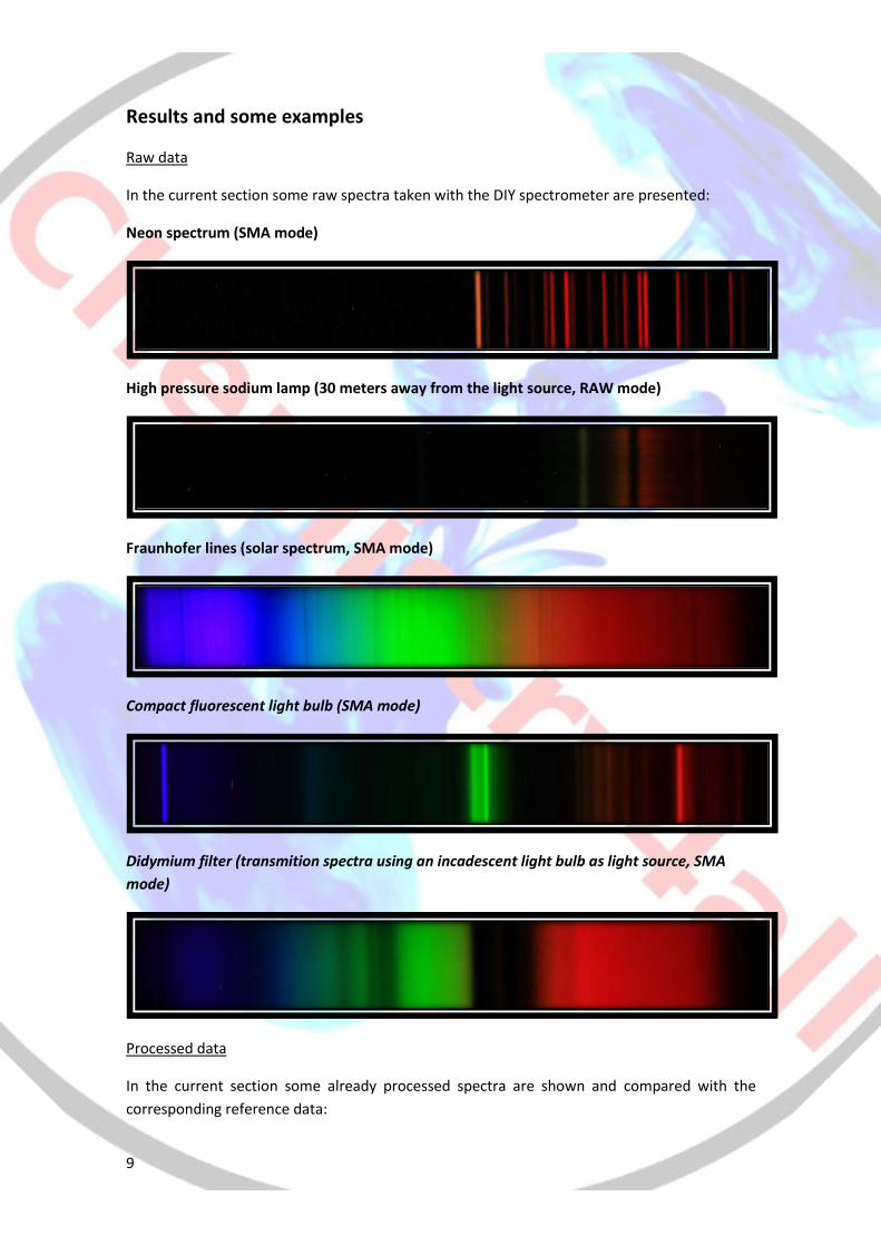
Results and some examples
Raw data
In the current section some raw spectra taken with the DIY spectrometer are presented:
Neon spectrum (SMA mode)
High pressure sodium lamp (30 meters away from the light source, RAW mode)
Fraunhofer lines (solar spectrum, SMA mode)
Compact fluorescent light bulb (SMA mode)
Didymium filter (transmition spectra using an incadescent light bulb as light source, SMA
mode)
Processed data
In the current section some already processed spectra are shown and compared with the
corresponding reference data:

10
Neon spectrum (SMA mode)
Table 3. Comparison of the experimentally obtained Neon spectrum and the reference data.
High pressure sodium lamp (RAW mode) (30 meters away from the source)
Experimental peak (nm) Reference peak (nm) Absolute difference (nm)
585.8 585.25 0.55
588.8 588.19 0.61
594.9 594.48 0.42
598 597.55 0.45
603.4 603.00 0.40
607.7 607.43 0.27
609.9 609.62 0.28
614.5 614.31 0.19
616.5 616.36 0.14
621.9 621.73 0.17
Mean difference 0.35
11
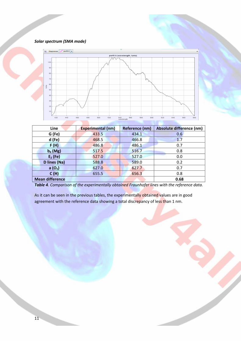
Solar spectrum (SMA mode)
Line Experimental (nm) Reference (nm) Absolute difference (nm)
G (Fe) 433.5 434.1 0.6
d (Fe) 468.5 466.8 1.7
F (H) 486.8 486.1 0.7
b4 (Mg) 517.5 516.7 0.8
E2 (Fe) 527.0 527.0 0.0
D lines (Na) 588.8 589.0 0.2
a (O2) 627.0 627.7 0.7
C (H) 655.5 656.3 0.8
Mean difference 0.68
Table 4. Comparison of the experimentally obtained Fraunhofer lines with the reference data.
As it can be seen in the previous tables, the experimentally obtained values are in good
agreement with the reference data showing a total discrepancy of less than 1 nm.

12
Further development
Currently, the spectrometer could be further improved mainly through the development of
different accessories for specific applications or purposes. A good example of one of these
accessories might be a UV-VIS spectrophotometer unit:
UV-VIS absorption accessory (Still being developed)
A fully portable, battery powered and 3D printed UV-VIS absorption accessory was designed to
be coupled to the DIY spectrometer.
Figure 14. UV-VIS spectrophometer unit.
As shown in the previous image, the design of this accessory is pretty simple. A small 3.00 V
light bulb serves as a continues light source within the visible range (400-700 nm). The light is
then diffused and “homogenized” by a diffuser screen and after that it reaches the cuvette
holder, where a standard glass or plastic cuvette is placed. The incoming photons interact with
the molecules present in the solution, and some of them are absorbed promoting electronic
excitations associated with the chromophoric groups of the species present in the solution. A
fiber optic cable, connected to the unit through the SMA connector, collects the remaining
photons and redirects them to the spectrometer, where the spectrum is taken.
This accessory is especially oriented towards chemistry, and its range of applicability may
extend from the determination of the concentration of a solution to the study of the
absorption bands of a molecule within the UV-VIS range.

13
Plasma-induced optical emission spectroscopy unit (Still being developed)
In addition to the previously mentioned accessory, some other accessories are currently being
developed. One of them is a DIY plasma induced optical emission spectroscopy unit. This unit,
is designed for the study of certain kinds of gaseous sample though the analysis of the spectral
lines emitted by the corresponding plasma.
The working principle can be described as follows:
-A glass test tube, equipped with a rubber septum is purged with the gaseous sample to be
analyzed (usually a pure substance such as CO2, H2O or a noble gas).
-The tube is then evacuated several times (manually), using a regular medical syringe, until the
tube is partially evacuated.
-The tube is then placed and secured in the unit, where it is surrounded by two copper
electrodes connected to a bipolar Tesla coil.
Figure 15 . Electric discharge generated by the bipolar Tesla coil.
-The Tesla coil is then turned on and a stream of electrons passes between the electrodes and
through the evacuated tube. This stream of electrons causes the rapid formation of plasma, in
which the atoms get rapidly excited to higher electronic states. When the excited atoms get
relaxed to their ground state through different electronic transitions, energy is released as
photons, which can be detected by the spectrometer. The frequency of the emitted photons
depends on the electronic levels involved in the electronic transitions taking place, and hence
on the chemical nature of the sample.
This unit is particularly useful for physics experiments, as it can be used as a regular discharge
tube, generating the characteristic emission spectra of a given gaseous molecule or atom.
Despite the fact that it is not fully developed yet, here there are some examples of the plasma
created by the unit:
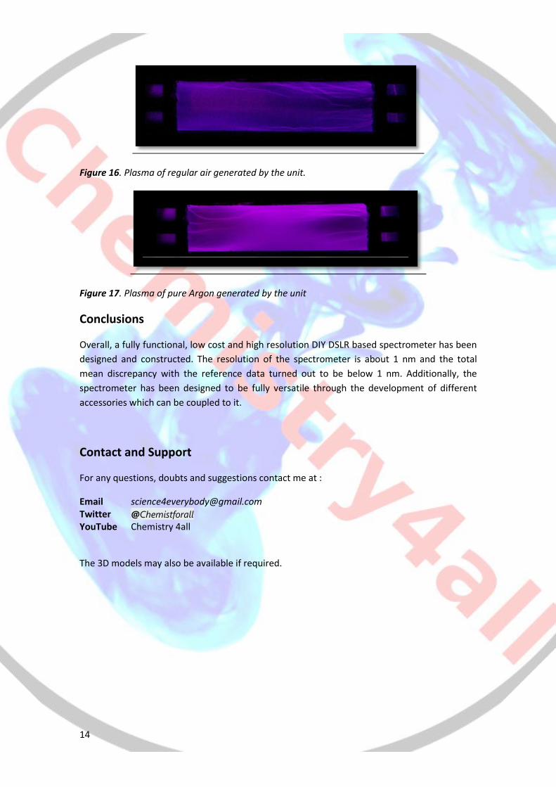
14
Figure 16. Plasma of regular air generated by the unit.
Figure 17. Plasma of pure Argon generated by the unit
Conclusions
Overall, a fully functional, low cost and high resolution DIY DSLR based spectrometer has been
designed and constructed. The resolution of the spectrometer is about 1 nm and the total
mean discrepancy with the reference data turned out to be below 1 nm. Additionally, the
spectrometer has been designed to be fully versatile through the development of different
accessories which can be coupled to it.
Contact and Support
For any questions, doubts and suggestions contact me at :
Email [email protected] Twitter @Chemistforall YouTube Chemistry 4all
The 3D models may also be available if required.