high speed induced flow reciprocating pumps
TRANSCRIPT
http://pme.sagepub.com/Engineers
Proceedings of the Institution of Mechanical
http://pme.sagepub.com/content/186/1/785The online version of this article can be found at:
DOI: 10.1243/PIME_PROC_1972_186_094_02
1972 186: 785Proceedings of the Institution of Mechanical EngineersR. L. Creedon, J. Lobo-Guerrero, P. R. Selwood and J. D. Burton
High Speed Induced Flow Reciprocating Pumps
Published by:
http://www.sagepublications.com
On behalf of:
Institution of Mechanical Engineers
can be found at:Proceedings of the Institution of Mechanical EngineersAdditional services and information for
http://pme.sagepub.com/cgi/alertsEmail Alerts:
http://pme.sagepub.com/subscriptionsSubscriptions:
http://www.sagepub.com/journalsReprints.navReprints:
http://www.sagepub.com/journalsPermissions.navPermissions:
What is This?
- Jun 1, 1972Version of Record >>
at SYRACUSE UNIV LIBRARY on November 23, 2013pme.sagepub.comDownloaded from at SYRACUSE UNIV LIBRARY on November 23, 2013pme.sagepub.comDownloaded from
785
FLUID MACHINERY GROUP
HIGH SPEED INDUCED FLOW RECIPROCATING PUMPS
R. L. Creedon* J. Lobo-Guerrero, BSct I?. R. Selwood, BSc, CEng, MIMechE$ J. D. Burton, BSc, PhDS
Reciprocating pumps have been used for many years in conjunction with an air vessel or hydraulic accumulator placed between pump and discharge line, in order to control maximum cylinder pressures and to reduce the work done in overcoming friction. The air vessel and the discharge line are, in fact, capacitive and inductive
components which together have some natural frequency generally different from the pump frequency. In this paper, it is shown that by matching the natural frequency of the discharge impedance to the pump frequency it is possible to obtain volumetric efficiencies of 200 per cent or more. This ‘induced flow principle’ was incorporated in a small high speed pump developed specifically to overcome the relative bulk and cost of conventional diaphragm pumps. Performance data for the new type of pump are compared with theoretical analogue computer solutions, and it appears that the induced flow principle may have a wider range of
application than originally anticipated.
1 INTRODUCTION FOR MANY YEARS reciprocating pumps have been used in conjunction with air vessels or capacitive components in order to reduce both the cylinder pressure and the power required in overcoming friction (I) (I. Usually the speed of the machine and the characteristics of the air chamber and pipeline are such that the volumetric efficiency is just below 100 per cent, this figure decreasing slightly as head is applied, owing to ‘slip’. Under certain conditions, how- ever, the volumetric efficiency may exceed 100 per cent and, ‘owing to the momentum of flow in the outlet tube, a back pressure is set up which tends to keep the valves open, thereby drawing more fluid through the pump’ (2). The authors had observed this type of ‘negative slip’ occurring in a conventional low speed (90 rev/min) reciprocating diaphragm pump, when a rigid discharge pipe was used rather than the normal flexible hose. Further investigation, and in due course a deeper insight into the dynamics of reciprocating pump behaviour, indicated how this phe- nomenon might be accentuated and controlled to produce a continuous ‘induced flow’ which could more than double machine output.
1.1 Notation A A , a
Cross-sectional area of the induction tube. Cross-sectional area of the piston. Acceleration of fluid in the induction tube.
This paper is published for written discussion. The M S . was received on 24th August 1971 and accepted for publication on 4th August 1972. 33
* Formerly, Development Engineer, William R . Selwood Ltd, Chandler’s Ford, Eastleigh, Hampshire SO5 3ZL.
t Research Student, Department of Mechanical Engineering, Uni- versity of Southampton, Southampton SO9 JNH.
$. Technical Director, WiLliam R . Selwood Ltd. s Departmento de Ingenieria Mecanica, Universidad de Los Andes, Facultad de Ingenieria, Bogotri, Columbia. Formerly, Development Engineer, William R . Selwood Ltd.
/I References are given in Appendix 2.
Proc lnstn Mech Engrs 1912
Capacitance. Linear dimension. Gravitational acceleration. Instantaneous static head in the capacitance. Static head across the system. Stiffness of the hydraulic capacitance. Inductance. Effective length of the induction tube. Rate of volumetric discharge. Half the piston stroke. Time. Induction tube velocity. Maximum effective piston velocity in terms of flow
rates created in the induction tube [= Qw4,IA)I.
Instantaneous velocity of flow into the capacitance in terms of flow rates created in the induction tube.
Instantaneous velocity of flow in the pump cylin- ders exit pipe, due to piston displacement in terms of flow rates created in the induction tube.
Specific weight of pumped fluid. Angular position in the cycle at the start of powered
Angular position in the cycle at the end of powered
Dimensionless flow (volumetric efficiency)
flow.
flow.
Dimensionless head
Angular velocity of reciprocator. Angular velocity corresponding to the natural fre-
quency of the combined inductance and capaci- tance.
Ratio of angular velocities (= frequency ratio).
Vol186 71/72
at SYRACUSE UNIV LIBRARY on November 23, 2013pme.sagepub.comDownloaded from
786 R. L. CREEDON, J. LOBO-GUERRERO, P. R. SELWOOD AND J. D. BURTON
I
-- Suction tank
Discharge tank
Flexing diaphragm seal
Fig. 1. Reciprocating pump with inductive and capacitive components
2 RECIPROCATING P U M P WITH INDUCED FLOW COMPONENTS
In Fig. 1 a single acting reciprocating pump is combined with the two hydraulic components necessary to generate the induced flow. The pump draws liquid from the suction tank, passes it to the pumping chamber via valve 1 (set into the piston crown) and thence to the discharge pipe via valve 2. After passing the capacitive and inductive components C and L, effectively a hydraulic accumulator and a rigid pipe, the liquid passes to the discharge tank which has a level h, above the suction tank.
Since the frequencies involved are low, it is possible to use a lumped-parameter approximation for the hydraulic components. Neglecting end effects the lumped inertance or inductance is defined by the geometry of the discharge line (31,
* (1) W L S
g A L = - . . . .
while the capacitance is 1 K"" C = - . (2)
where K is the stiffness constant of the accumulator and is defined as the pressure difference necessary to store a unit volume of fluid.
The angular velocity corresponding to the natural frequency of oscillation, for the parallel system shown in Fig. 1, is given by
As with any second order system subjected to a har- monically varying force (such as a piston moving with simple harmonic motion of angular velocity w), behaviour depends upon the damping ratio and the resonant angular velocity wo of the external impedance.
If the damping ratio is small, as it is in this case, then amplitude ratios greater than unity will be produced near w/wo = 1.0. Thus, by maintaining h, and w constant and varying w (through length and stiffness changes to re- spectively the inductance and capacitance), the discharge capacity and volumetric efficiency may be made to vary in the manner indicated in Fig. 2. Volumetric efficiencies of near unity give place to values of around 200 per cent, this figure dropping rapidly once resonance is passed. The curve, in fact, looks very like a typical resonance curve for a second order system.
"0 0.2 0.4 0.6 0.8 t.0 1.2 14 1.6 "I",
Fig. 2. Volumetric efficiency versus angular velocity ratios for different heads
Evidently the nature of the flow perturbations in the induction pipe L will be greatly influenced by the fre- quency ratio w/wo.
At low values of w/wo (region A in Fig. 2) where K is high and the inductive length short, the induction tube velocity V will follow that of the effective piston velocity V,,, or ring near to it as in Fig. 3a. Volumetric efficiency is close to unity and insensitive to head change (Fig. 2). A practical example of this type of flow cycle would be that occurring in a slow running site drainage diaphragm pump connected to a short flexible hose.
At high values of w/wo (region B in Fig. 2), a large capacitance or air vessel, with a very low stiffness K has been interposed between the pump and a long rigid pipe- line. In this case the flow velocity fluctuation V will be 180" out of phase with the effective piston velocity V, and volumetric efficiency again will be close to unity and in- sensitive to head change (Fig. 36).
By choosing the appropriate inductance and capacitance and isolating them from the main pipeline by a second capacitance (or by other design means) it is possible to operate the pump a little below the resonant frequency of components. Under these conditions, volumetric efficiency (at least for low heads) will be over 200 per cent, and the
Val 186 71/72 Proc lnstn Mech Engrs 1972
at SYRACUSE UNIV LIBRARY on November 23, 2013pme.sagepub.comDownloaded from
HIGH SPEED INDUCED FLOW RECIPROCATING PUMPS 787
TIME U
\ f TIME
C TIME
a Low angular velocity ratio w / w 0 Q 1.0. b High angular velocity ratio w/wo S 1.0. c Angular velocity ratio close to unity (low head case).
velocity of the discharged flow Fig. 3. Pump to angular velocity ratio effect on the
flow pattern in the induction tube will be similar to that depicted in Fig. 3c.
Referring to Fig. 3c, the induced flow cycle with its high volumetric efficiency may be explained as follows. At point A the output flow velocity V is equal to the effective piston velocity V,, so the piston valve closes and the piston commences to work (it should be noted that valve 2 is continually open under the operating conditions shown). Between A and B V, is greater than V, so fluid is stored in the capacitance. If the head in the capacitance is h, at any instant, the fluid in the induction pipe will suffer an acceleration given by
g 43 a = (hc-ho)- . . .
At point B h, = ho and the acceleration a will be zero, giving the minimum velocity. Between B and C the capacitance has accumulated enough fluid to make h, > h,, so that a will be positive and still more fluid is stored in the capacitance.
At point C V, equals V and the fluid stored in the capacitance will be maximum, giving ho maximum. Be- tween C and D the acceleration a is still positive, although h, is gradually reducing as the capacitance discharges its volume to the main flow. At D h, = h,, therefore u = 0, and the maximum velocity is obtained. Between D and E h, < ho, the fluid will then decelerate, while the capaci- tance discharges the remaining fluid it contained.
At E all the fluid has been discharged from the capaci- tance h, = 0 and the piston valve 1 will open, placing suction and discharge tanks in communication.
Between E and A the fluid will flow freely and will retard at a constant rate a = -(h,/L,)g, due to its induc- tance. At A the cycle recommences. A summary of the dynamics of the cycle is now given.
(1) The flow discharged from the system is continuous with maximum velocity indicated by point D and mini- mum velocity by point B.
(2) The volume discharged is equivalent to the area under the curve of V whilst the volume swept by the piston is the area under the curve of V,, hence, the volu- metric efficiency greatly exceeds 100 per cent.
(3) The hatched area is representative of the volume stored and delivered by the capacitance each cycle.
(4) The induced flow or inertia flow occurs throughout more than half the cycle, i.e. from E to A; while the powered flow occurs from A to E.
From equation (4) it can be seen that the external head h, on the pump will influence the magnitude of fluid accelerations and also the relative proportions of the cycle occupied by the powered and inertia flows. In order to understand more clearly the effects of various heads and frequencies on the pump performance, a mathematical model was developed. As always several assumptions and simplifications were made which account for the differences obtained between theory and observation. However, the utility of the solutions can best be judged in the light of comparison with experimental results presented later. The development of the mathematical model can be found in Appendix 1.
The differential equations describing the flow are
where $ is the dimensionless head across the pump and is defined by equation (7)
(7)
and is effectively the discharge pressure divided by the pressure developed in the capacitance when storing 0.55 of the pump swept volume. This definition ensures that when the pump is functioning as a conventional recipro- cator (i.e., with w/wo % 1.0 as in Fig. 3b) + = 1.0.
At this point is is also useful to define the dimensionless flow coefficient + as the volumetric efficiency
T Q
A Va +=- . . .
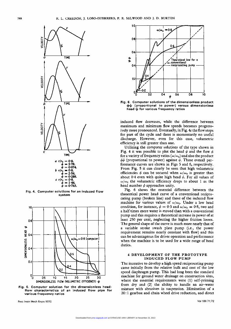
3 THEORETICAL I N D U C E D FLOW P U M P PERFORMANCE
Although analytical solutions for equations (5) and (6) were obtained (4), their complexity was such that an analogue computer was found to be much more useful in exploring the various modes of pump operation. Fig. 4 shows typical solutions obtained for different heads ho while w/wo was held at 0.8. It can clearly be seen that as ho increases, the proportion of the cycle occupied by the
Proc lnstn Mech Engrs 1972 Vol 186 71/72
at SYRACUSE UNIV LIBRARY on November 23, 2013pme.sagepub.comDownloaded from
788 R. L. CREEDON, J. LOBO-GUERRERO, P. R. SELWOOD AND J. D. BURTON
u r/ro = 0.8.
b r/ro = 0.8.
c r/ro = 0.8.
4 = 2.78. $ = 0.074.
4 = 2.54 8 p = 0.288.
4 = 1.44. $ = 0.743.
Fig. 4. Computer solutions for an induced f low system
DIMENSIONLESS FLOW (VOLUMETRIC EFFICIENCY) 4 Fig. 5. Computer solution for the dimensionless head-
flow characteristics of an induced flow pipe for various frequency ratios
Proc lnstn Mech Engrs 1972
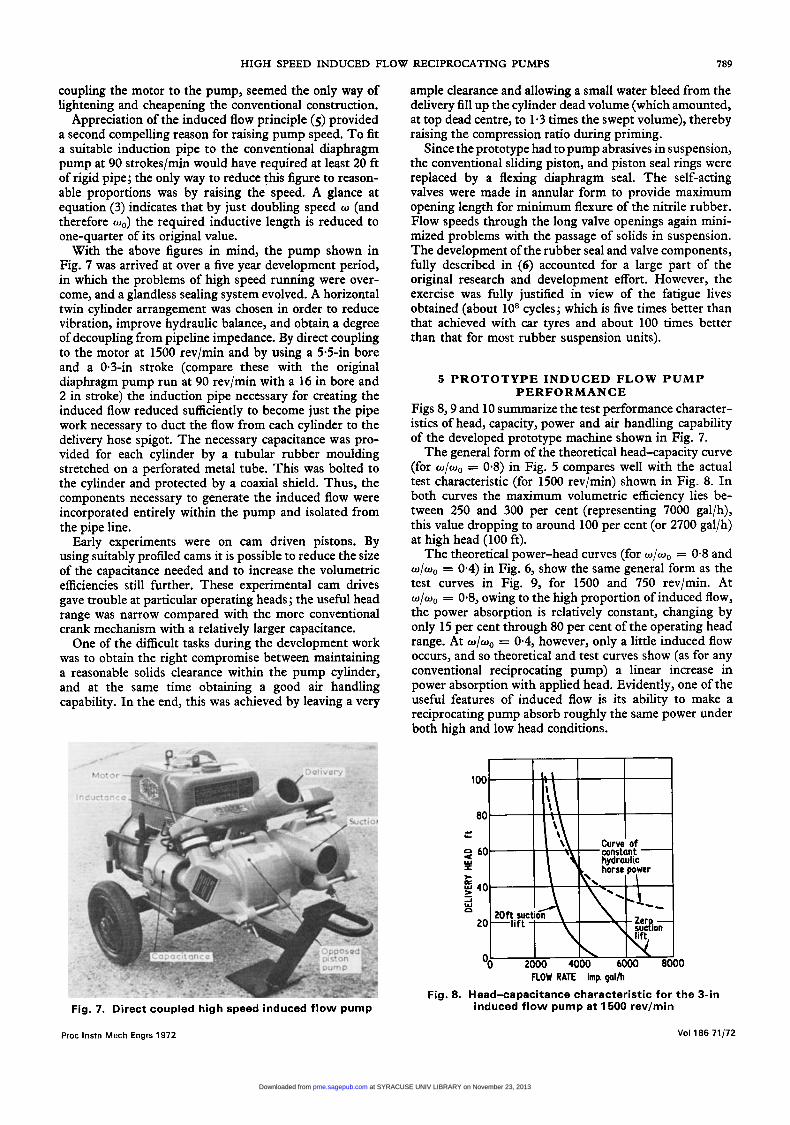
Fig. 6. Computer solutions of the dimensionless product r$$ (proportional to power) versus dimensionless head $ for various frequency ratios
induced flow decreases, while the difference between maximum and minimum flow speeds becomes progress- ively more pronounced. Eventually, in Fig. 4c the flow stops for part of the cycle and there is momentarily no useful discharge. However, even for this case, volumetric efficiency is still greater than one.
Utilizing the computer solutions of the type shown in Fig. 4 it was possible to plot the head (CI and the flow 4 for a variety of frequency ratios (w/wo) and also the product +(CI (proportional to power) against (CI. These overall per- formance curves are shown in Figs 5 and 6, respectively. From Fig. 5 it can clearly be seen that high volumetric efficiencies 4 can be secured when w/wo is greater than about 0.4 even with quite high head 4. For all values of w/wo the volumetric efficiency drops to about 1 as the head number (CI approaches unity.
Fig. 6 shows the essential difference between the theoretical power head curve of a conventional recipro- cating pump (broken line) and those of the induced flow machine for various values of w/wo. Under a low head condition, for instance, (CI = 0.3 and w/wo = 0.8, two and a half times more water is moved than with a conventional pump and this requires a theoretical increase in power of at least 250 per cent, neglecting the higher friction losses. The general shape of the curve is much more nearly that of a variable stroke swash plate pump (ie., the power requirement remains nearly constant with flow) and this can be advantageous for driver operation and performance when the machine is to be used for a wide range of head duties.
4 DEVELOPMENT OF THE PROTOTYPE INDUCED FLOW PUMP
The incentive to develop a high speed reciprocating pump came initially from the relative bulk and cost of the low speed diaphragm pump. This had long been the standard machine for ground water drainage on construction sites, where the essential requirements were (1) self-priming from dry and (2) the ability to handle an air-water mixture with abrasives in suspension. Elimination of a 20: 1 gearbox and chain wheel drive reduction, and direct
Vol 186 71,172
at SYRACUSE UNIV LIBRARY on November 23, 2013pme.sagepub.comDownloaded from
HIGH SPEED INDUCED FLOW RECIPROCATING PUMPS 789
coupling the motor to the pump, seemed the only way of lightening and cheapening the conventional construction.
Appreciation of the induced flow principle (5) provided a second compelling reason for raising pump speed. To fit a suitable induction pipe to the conventional diaphragm pump at 90 strokes/min would have required at least 20 ft of rigid pipe; the only way to reduce this figure to reason- able proportions was by raising the speed. A glance at equation (3) indicates that by just doubling speed w (and therefore wo) the required inductive length is reduced to one-quarter of its original value.
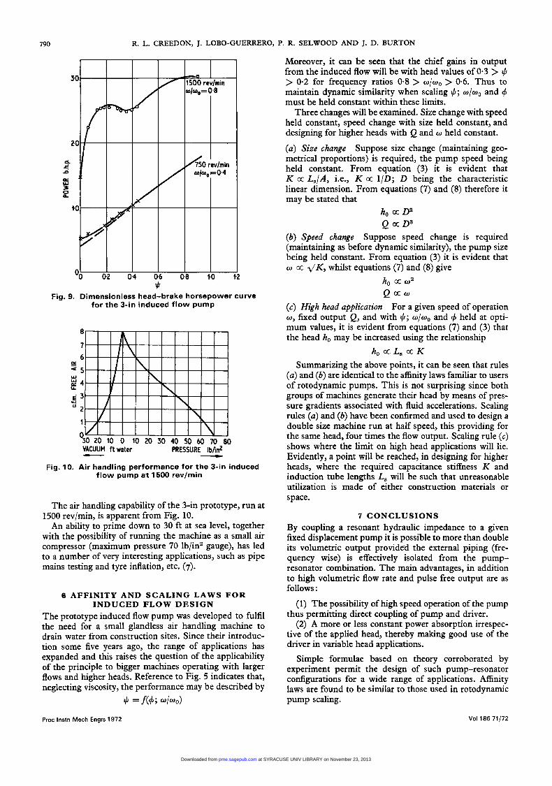
With the above figures in mind, the pump shown in Fig. 7 was arrived at over a five year development period, in which the problems of high speed running were over- come, and a glandless sealing system evolved. A horizontal twin cylinder arrangement was chosen in order to reduce vibration, improve hydraulic balance, and obtain a degree of decoupling from pipeline impedance. By direct coupling to the motor at 1500 rev/min and by using a 5.5411 bore and a 0.3-in stroke (compare these with the original diaphragm pump run at 90 rev/min with a 16 in bore and 2 in stroke) the induction pipe necessary for creating the induced flow reduced sufficiently to become just the pipe work necessary to duct the flow from each cylinder to the delivery hose spigot. The necessary capacitance was pro- vided for each cylinder by a tubular rubber moulding stretched on a perforated metal tube. This was bolted to the cylinder and protected by a coaxial shield. Thus, the components necessary to generate the induced flow were incorporated entirely within the pump and isolated from the pipe line.
Early experiments were on cam driven pistons. By using suitably profiled cams it is possible to reduce the size of the capacitance needed and to increase the volumetric efficiencies still further. These experimental cam drives gave trouble at particular operating heads ; the useful head range was narrow compared with the more conventional crank mechanism with a relatively larger capacitance.
One of the difficult tasks during the development work was to obtain the right compromise between maintaining a reasonable solids clearance within the pump cylinder, and at the same time obtaining a good air handling capability. In the end, this was achieved by leaving a very
Fig. 7. Direct coupled high speed induced flow pump
ample clearance and allowing a small water bleed from the delivery fill up the cylinder dead volume (which amounted, at top dead centre, to 1.3 times the swept volume), thereby raising the compression ratio during priming.
Since the prototype had to pump abrasives in suspension, the conventional sliding piston, and piston seal rings were replaced by a flexing diaphragm seal. The self-acting valves were made in annular form to provide maximum opening length for minimum flexure of the nitrile rubber. Flow speeds through the long valve openings again mini- mized problems with the passage of solids in suspension. The development of the rubber seal and valve components, fully described in (6) accounted for a large part of the original research and development effort. However, the exercise was fully justified in view of the fatigue lives obtained (about lo8 cycles; which is five times better than that achieved with car tyres and about 100 times better than that for most rubber suspension units).
5 PROTOTYPE INDUCED FLOW P U M P PERFORMANCE
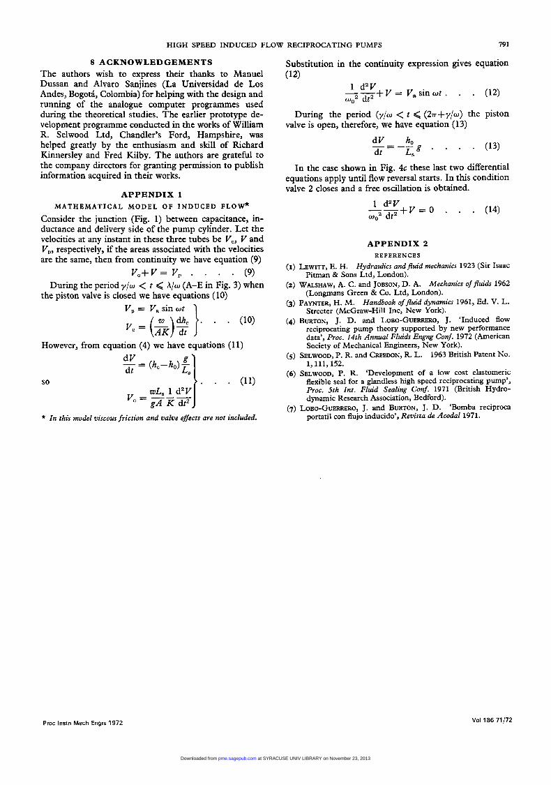
Figs 8,9 and 10 summarize the test performance character- istics of head, capacity, power and air handling capability of the developed prototype machine shown in Fig. 7.
The general form of the theoretical head-capacity curve (for w/wo = 0.8) in Fig. 5 compares well with the actual test characteristic (for 1500 rev/min) shown in Fig. 8. In both curves the maximum volumetric efficiency lies be- tween 250 and 300 per cent (representing 7000 gal/h), this value dropping to around 100 per cent (or 2700 gal/h) at high head (100 ft).
The theoretical power-head curves (for w/wo = 0.8 and w/wo = 0.4) in Fig. 6, show the same general form as the test curves in Fig. 9, for 1500 and 750 rev/min. At w/wo = 0.8, owing to the high proportion of induced flow, the power absorption is relatively constant, changing by only 15 per cent through 80 per cent of the operating head range. At w/w0 = 0.4, however, only a little induced flow occurs, and so theoretical and test curves show (as for any conventional reciprocating pump) a linear increase in power absorption with applied head. Evidently, one of the useful features of induced flow is its ability to make a reciprocating pump absorb roughly the same power under both high and low head conditions.
I I I I
I Curve o f
FLOW RATE imp galh
induced flow pump at 1500 rev/min Fig. 8. Head-capacitance characteristic for the 3-in
Proc lnstn Mech Engrs 1972 Vol186 71/72
at SYRACUSE UNIV LIBRARY on November 23, 2013pme.sagepub.comDownloaded from
790 R. L. CREEDON, J. LOBO-GUERRERO, P. R. SELWOOD AND J. D. BURTON
$ Fig. 9. Dimensionless head-brake horsepower curve
for the 3-in induced flow pump
- Fig. 10. Air handling performance for the 3-in induced
flow pump a t 1500 rev/min
The air handling capability of the 3-in prototype, run at 1500 rev/min, is apparent from Fig. 10.
An ability to prime down to 30 ft at sea level, together with the possibility of running the machine as a small air compressor (maximum pressure 70 lb/in2 gauge), has led to a number of very interesting applications, such as pipe mains testing and tyre inflation, etc. (7).
6 AFFINITY AND SCALING LAWS FOR INDUCED FLOW DESIGN
The prototype induced flow pump was developed to fulfil the need for a small glandless air handling machine to drain water from construction sites. Since their introduc- tion some five years ago, the range of applications has expanded and this raises the question of the applicability of the principle to bigger machines operating with larger flows and higher heads. Reference to Fig. 5 indicates that, neglecting viscosity, the performance may be described by
+ = f(4; w h o )
Moreover, it can be seen that the chief gains in output from the induced flow will be with head values of 0.3 > + > 0.2 for frequency ratios 0.8 > w / w o > 0.6. Thus to maintain dynamic similarity when scaling Q; w/wo and 4 must be held constant within these limits.
Three changes will be examined. Size change with speed held constant, speed change with size held constant, and designing for higher heads with Q and w held constant.
( a ) Size change Suppose size change (maintaining geo- metrical proportions) is required, the pump speed being held constant. From equation (3) it is evident that K cc LJA, i.e., K cc 1/D; D being the characteristic linear dimension. From equations (7) and (8) therefore it may be stated that
h, a Da Q a D 3
(b) Speed change Suppose speed change is required (maintaining as before dynamic similarity), the pump size being held constant. From equation (3) it is evident that w cc d K , whilst equations (7) and (8) give
ho K w2
Q a w (c) High head application For a given speed of operation w, fixed output Q, and with +; w/wo and 4 held at opti- mum values, it is evident from equations (7) and (3) that the head ho may be increased using the relationship
h, cc L, cc K Summarizing the above points, it can be seen that rules
(a) and (b) are identical to the affinity laws familiar to users of rotodynamic pumps. This is not surprising since both groups of machines generate their head by means of pres- sure gradients associated with fluid accelerations. Scaling rules (a) and (b) have been confirmed and used to design a double size machine run at half speed, this providing for the same head, four times the flow output. Scaling rule (c) shows where the limit on high head applications will lie. Evidently, a point will be reached, in designing for higher heads, where the required capacitance stiffness K and induction tube lengths L, will be such that unreasonable utilization is made of either construction materials or space.
7 CONCLUSIONS By coupling a resonant hydraulic impedance to a given fixed displacement pump it is possible to more than double its volumetric output pr0vide.d the external piping (fre- quency wise) is effectively isolated from the pump- resonator combination. The main advantages, in addition to high volumetric flow rate and pulse free output are as follows :
(1) The possibility of high speed operation of the pump thus permitting direct coupling of pump and driver.
(2) A more or less constant power absorption irrespec- tive of the applied head, thereby making good use of the driver in variable head applications.
Simple formulae based on theory corroborated by experiment permit the design of such pump-resonator configurations for a wide range of applications. Affinity laws are found to be similar to those used in rotodynamic pump scaling.
Vol 186 71/72 Proc lnstn Mech Engrs 1972
at SYRACUSE UNIV LIBRARY on November 23, 2013pme.sagepub.comDownloaded from
HIGH SPEED INDUCED FLOW RECIPROCATING PUMPS 79 1
8 ACKNOWLEDGEMENTS The authors wish to express their thanks to Manuel Dussan and Alvaro Sanjines (La Universidad de Los Andes, Bogotl, Colombia) for helping with the design and running of the analogue computer programmes used during the theoretical studies. The earlier prototype de- velopment programme conducted in the works of William R. Selwood Ltd, Chandler’s Ford, Hampshire, was helped greatly by the enthusiasm and skill of Richard Kinnersley and Fred Kilby. The authors are grateful to the company directors for granting permission to publish information acquired in their works.
APPENDIX 1 M A T H E M A T I C A L M O D E L O F INDUCED FLOW*
Consider the junction (Fig. 1) between capacitance, in- ductance and delivery side of the pump cylinder. Let the velocities at any instant in these three tubes be V,, V and V,, respectively, if the areas associated with the velocities are the same, then from continuity we have equation (9)
During the period y/w < t Q A/w (A-E in Fig. 3) when
V, = V,sinwt
Vc+V= V, . . . . (9)
the piston valve is closed we have equations (10)
However, from equation (4) we have equations (11)
so
dV - dt = (hc--ho)L,
> . . wL, 1 d2V
- g A K dt2 V
* In this model viscous friction and valve effects are not included.
Substitution in the continuity expression gives equation (12)
+V = V,sinwt . . . (12) 1 d2V
wo2 dt2 --
During the period (y /w < t < (2n-+y/w) the piston valve is open, therefore, we have equation (13)
. . . (13) dV ho dt L S g *
_ - - --
In the case shown in Fig. 4c these last two differential equations apply until flow reversal starts. In this condition valve 2 closes and a free oscillation is obtained.
+ V = O . . . 1 d2V wo2 dt2 --
APPENDIX 2 REFERENCES
(I) LEWITT, E . H. Hydraulics andfluid mechanics 1923 (Sir Isaac Pitman & Sons Ltd, London).
(2) WALSHAW, A. C. and JOBSON, D. A. Mechanics of fluids 1962 (Longmans Green & Co. Ltd, London).
(3) PAYNTER, H. M. Handbook of fluid dynamics 1961, Ed. V. L. Streeter (McGraw-Hill Inc, New York).
(4) BURTON, J. D. and LOBO-GUERRERO, J. ‘Induced flow reciprocating pump theory supported by new performance data’, Proc. 14th Annual Fluids Engng Conf. 1972 (American Society of Mechanical Engineers, New York).
1963 British Patent No. 1,111, 152.
‘Development of a low cost elastomeric flexible seal for a glandless high speed reciprocating pump’, Proc. 5th Znt. Fluid Sealing Conf. 1971 (British Hydro- dynamic Research Association, Bedford).
‘Bomba reciproca portatil con flujo inducido’, Revista de Acodal 1971.
(5 ) SELWOOD, P. R. and CREEDON, R. L.
(6) SELWOOD, P. R.
(7) LOBO-GUERRERO, J. and BURTON, J. D.
Proc lnstn Mech Engrs 1972 Vol 186 71/72
at SYRACUSE UNIV LIBRARY on November 23, 2013pme.sagepub.comDownloaded from