high speed machining (hsc) of sculptured surfaces in … speed machining (hsc) of sculptured...
TRANSCRIPT
High Speed Machining (HSC) of Sculptured Surfaces in Die and Mold Manufacturing
Thorsten Finzer ([email protected] Darmstadt Universtiy o/Technology, Germany
Key words: High speed machining, die and mold manufacturing, cutting strategies
Abstract: In order to use the next generation of high-speed machine tools economically, first of all the technological background of the best machining strategies has to be found out. For this purpose four approaches in the machining process have to be made simultaneously. These approaches are the optimization of the machining parameters, the choose of the right cutting edge material and cutting tool and the use of proper machining strategies. The economic application of the best milling strategies depends on the dynamic capabilities of the machine tool. Therefore, machines with linear motor drives will become more and more important for die and mold production.
1. INTRODUCTION
High speed cutting has many principal advantages. By increasing the cutting speed it is possible to reduce the cutting forces, to dissipate process heat completely with chip removal, to generate better surfaces, to increase the metal removal rate and to perform machining in a range of uncritical vibration. The cutting speed mainly depends on the work-piece material.
copper, bronce. brass
cast-iron
steel
titanium
10
D transition area _ HSC-area
100 1000 cutting speed v,l mlmin I
100000
feed rate Imm/min]
---,---------,2oo00
L 1 mm 80000 z: 1
r- O:l0mm J I2000
f / /1 /" .,.. r"" / D=20mm
20000 /...- 4000
oL// I 10
o 500 1000 1500 10000
cutting speed v, I mlmin )
calculated with maximum diameter in use
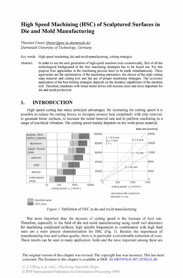
Figure 1. Definition of HSC in die and mold manufacturing
But more important than the increase of cutting speed is the increase of feed rate. Therefore, especially in the field of die and mold manufacturing using small tool diameters for machining sculptured surfaces, high spindle frequencies in combination with high feed rates are a more precise characterization for HSC (Fig. I). Besides the importance of manufacturing time and surface quality, there is in particular a considerable reduction of costs. These results can be seen in many application fields and the most important among these are
The original version of this chapter was revised: The copyright line was incorrect. This has beencorrected. The Erratum to this chapter is available at DOI:
© IFIP International Federation for Information Processing 1999
10.1007/978-0-387-35392-0_40
G. J. Olling et al. (eds.), Machining Impossible Shapes
dies and molds, aerospace parts and critical thin-walled components susceptible to heat distortion.
tool life [m] 250
200
150 .··h,-
100
'",
",
/ 1\ II '1
.I.
tool life [m[ 250
200
150
100 ."
/ Vern: 435 m/min
/""
width of wear land:
f 0.15mm width of wear land: - t2vom: 260 mlmin -0.1 mm I .- I
50 50
o a 200 400
a 600 a 0,05 0,1 0,15
cutting speed [mlmin] ,-_ _ ______ --, feed per tooth [mm]
workpiece:
X100CrMoV51 (2363) 60HRC
-... CBN - solid carbide (TiN-coated) ...... Cermet
tool:
ball head: 1216 mm number of teeth: 2 (CaN: 1) cutting material: solid carbide (TiN),
CaN, Cermet overhang: 24 mm (CaN: 30 mm)
technology:
up-cutlreverse-cut tilting angle: +15 cutting depth: 0.1 mm line space: 0.2 mm
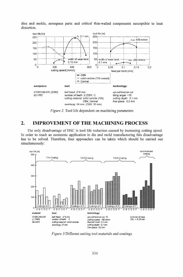
Figure 2. Tool life dependent on machining parameters
2. IMPROVEMENT OF THE MACHINING PROCESS
0,2
The only disadvantage of HSC is tool life reduction caused by increasing cutting speed. In order to reach an economic application in die and mold manufacturing this disadvantage has to be solved. Therefore, four approaches can be taken which should be carried out simultaneously:
mater/al:
X100crMoV51 (1.2363) 58HRC
TiN·Coating ToCNe_ng TWN-CoatJng ______ ____ ____
tool:
bal/head: t2f 6rrrn nurrtier of teeth: 2 cutting I7Bterial: solid carbide overhang: 27 mn
technology:
up-cut/reverse cut, 15 cutting speed: 180 m'rrin feed per looth: 0, 1 rrrn cutting de{ih: 0,1 rrrn fine space: 0, 2 mn
criterion of VIoear Vern = 0.15nm
Figure 3 Different cutting tool materials and coatings
334
2.1 Optimization of the machining parameters
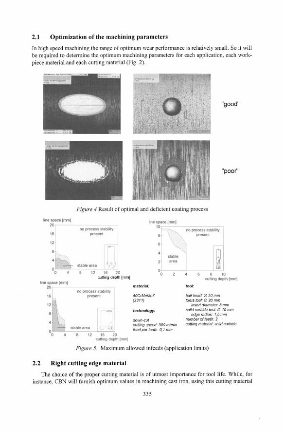
In high speed machining the range of optimum wear performance is relatively small. So it will be required to determine the optimum machining parameters for each application, each workpiece material and each cutting material (Fig. 2).
"good"
"poor"
Figure 4 Result of optimal and deficient coating process
line space (mm) 20
f 16
12
8 '
line space (mm] 20
16
no process slabll,ty present
stable area
8 12 16 20 cutting depth [mmJ
no process stabollty present
stable area • L-__
4 8 12 16 20 culling depth (mm)
line space (mm] 10
8
6
slable 2 area
no process stability present
0-- --024 6 8 10
material:
40CrMnM07 (231 1)
technology:
down-cut cutting speed: 300 mlmin feed per tooth: 0,1 mm
cutting depth (mm)
tool:
ball head: 0 20 mm torus tool: 0 20 mm
insert diameter: 8 mm solid carbide tool: '" 10 mm
edge radius: 1,5 mm number ofleeth: 2 cutting material: solid carbide
Figure 5. Maximum allowed infeeds (application limits)
2.2 Right cutting edge material
The choice of the proper cutting material is of utmost importance for tool life. While, for instance, CBN will furnish optimum values in machining cast iron, using this cutting material
335
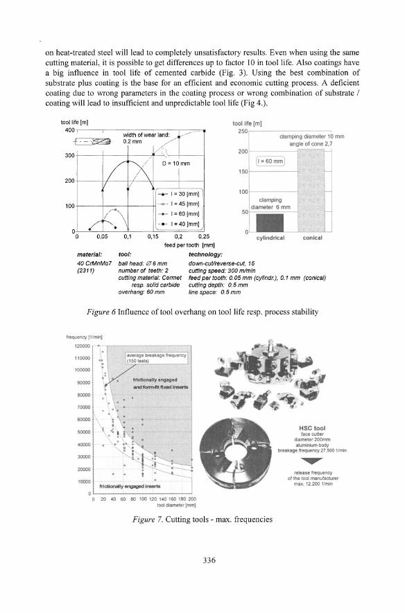
on heat-treated steel will lead to completely unsatisfactory results. Even when using the same cutting material, it is possible to get differences up to factor lOin tool life. Also coatings have a big influence in tool life of cemented carbide (Fig. 3). Using the best combination of substrate plus coating is the base for an efficient and economic cutting process. A deficient coating due to wrong parameters in the coating process or wrong combination of substrate / coating will lead to insufficient and unpredictable tool life (Fig 4.).
toollife[m] 400
.... . - '" 250r-of 0.2mm
I IX D= 10mm
I II i
300
200
___ I = 30 [mm]
100 ....•.... 1=45 [mm]
/--" --+-- I = 60 [mm] / ' •. \ ....• .... 1= 40 [mm] '. \
200 -
damping diameter 10 ITVT1
angle of cone 2,7
150Q=60mm
100
damping diameler 6 mm
50r-,===:----J:
o o
//' 0,05 0,1 0,15 0,2 0,25 cylindrical conical
material:
40CrMnM07 (2311)
tool:
feed per tooth [mm]
technology:
down-cutlreverse-cut, 15 cutting speed: 300 mlmin
ball head: 0 6 mm number of teeth: 2 cutting material: Cennet
resp. solid carbide overhang: 60 mm
feed per tooth: 0.05 mm (cyfindr.), 0.1 mm (conical) cutting depth: 0.5 mm fine space: 0.5 mm
Figure 6 Influence of tool overhang on tool life resp. process stability
Iroquency (1'''''''1 120000
110000
100000 . 90000
aoooo
70000
50000
50000
40000
30000
20000
10000
:
.. .. : • " . !
.ver.ge brelkage rrequency (150 testo)
frictionally engagod IRlformfItfl_l_
.' ... !
oL-__________________
o 20 40 60 80 100 120 140 160 180 200 1001 dLamet@rlmml
Figure 7. Cutting tools - max. frequencies
336
HSC tool f-ace CLlner
diameter 200mn 'Iurronium-bOdy
breakage frequency 27.500 lJrnin
release frequency of the 1001
max. 12 200 1/mln
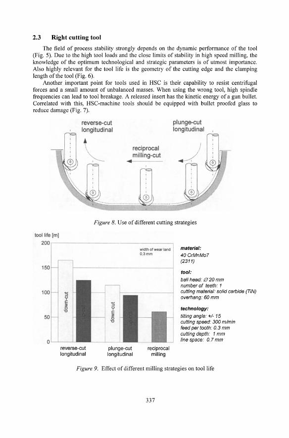
2.3 Right cutting tool
The field of process stability strongly depends on the dynamic performance of the tool (Fig. 5). Due to the high tool loads and the close limits of stability in high speed milling, the knowledge of the optimum technological and strategic parameters is of utmost importance. Also highly relevant for the tool life is the geometry of the cutting edge and the clamping length of the tool (Fig. 6).
Another important point for tools used in HSC is their capability to resist centrifugal forces and a small amount of unbalanced masses. When using the wrong tool, high spindle frequencies can lead to tool breakage. A released insert has the kinetic energy of a gun bullet. Correlated with this, HSC-machine tools should be equipped with bullet proofed glass to reduce damage (Fig. 7).
reverse-cut longitudinal
reciprocal milling-cut
plunge-cut longitudinal
Figure 8. Use of different cutting strategies
tool life [m]
200 ,-----------------
150
l00H '5 If c:
0 '0
50
OL.......L---'-reverse-cut longitudinal
plunge-cut longitudinal
width of wear land I O.3mm
I
reciprocal milling
I
material: 40CrMnMo7 (2311)
tool:
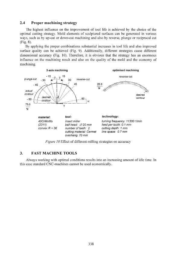
ball head: 0 20 mm number of teeth: 1 cutting material: solid carbide (TiN) overhang: 60 mm
technology: tilting angle: +1- 15 cutting speed: 300 mlmin feed per tooth: 0.3 mm cutting depth: 1 mm line space: 0.7 mm
Figure 9. Effect of different milling strategies on tool life
337
2.4 Proper machining strategy
The highest influence on the improvement of tool life is achieved by the choice of the optimal cutting strategy. Mold elements of sculptured surfaces can be generated in various ways, such as by up-cut or down-cut machining and also by reverse, plunge or reciprocal cut (Fig. 8).
By applying the proper combinations substantial increases in tool life and also improved surface quality can be achieved (Fig. 9). Additionally, different strategies cause different dimensional accuracy (Fig. 10). Therefore, it is obvious that the strategy has an enormous influence on the machining result and also on the quality of the mold and the economy of machining.
plunge-cut
3-axis machining
- 15 _ Il 15 -30 30 reverse-cut
material: 40CrMnMo (2311) convex R =36
tool:
insert miller ball head: f2f 20 mm number of teeth: 2 cutting material: Cermet overhang: 70 mm
optimised machining
reverse-cut
'"
technology:
desired contour
turning frequency: 11300 11min feed per tooth: 0.1 mm cutting depth: 1 mm line space: 0.7 mm
Figure 10 Effect of different milling strategies on accuracy
3_ FAST MACHINE TOOLS
Always working with optimal conditions results into an increasing amount of idle time. In this case standard CNC-machines cannot be used economically.
338
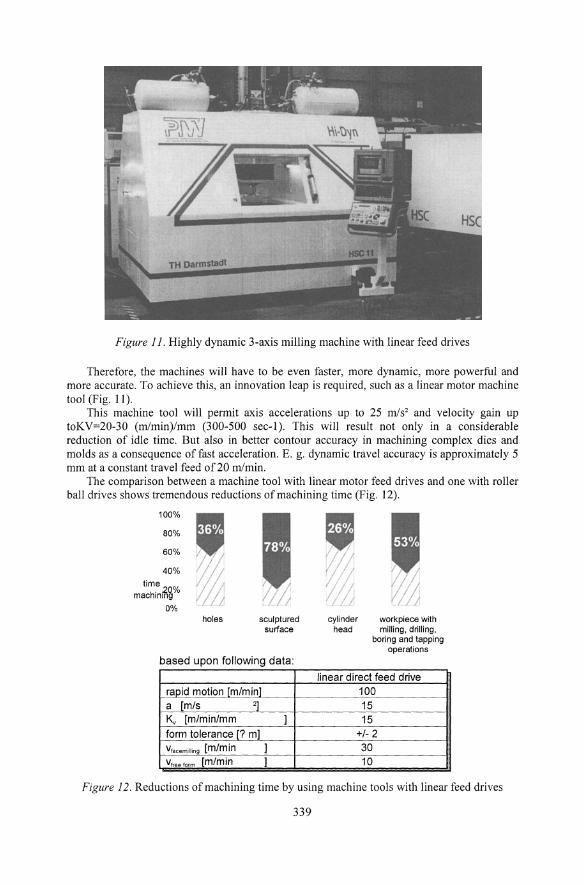
Figure 11. Highly dynamic 3-axis milling machine with linear feed drives
Therefore, the machines will have to be even faster, more dynamic, more powerful and more accurate. To achieve this, an innovation leap is required, such as a linear motor machine tool (Fig. II).
This machine tool will permit axis accelerations up to 25 mls2 and velocity gain up toKV=20-30 (mlmin)/mm (300-500 sec-I). This will result not only in a considerable reduction of idle time. But also in better contour accuracy in machining complex dies and molds as a consequence of fast acceleration. E. g. dynamic travel accuracy is approximately 5 mm at a constant travel feed of20 mlmin.
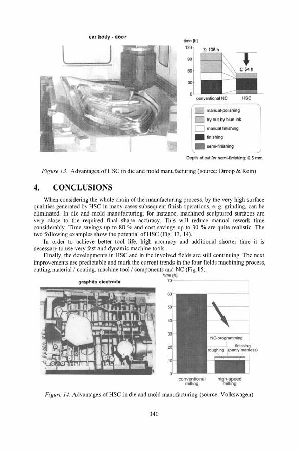
The comparison between a machine tool with linear motor feed drives and one with roller ball drives shows tremendous reductions of machining time (Fig. 12).
100% , 80%
60%
40%
time.20% machining
0% holes sculptured cylinder workpiece with
surface head milling, drilling, boring and tapping
operations
based upon following data:
linear direct feed drive rapid motion [m/min] 100 a [m/s 2] 15 K., [m/min/mm ] 15 form tolerance [? m] +/- 2 Vfacemilling [m/min ] 30 V' eefmm [m/min ] 10
Figure 12. Reductions of machining time by using machine tools with linear feed drives
339
time(hJ
120
90
60
conventional NC HSC
manual-polishing
Figure 13. Advantages ofHSC in die and mold manufacturing (source: Droop & Rein)
4. CONCLUSIONS When considering the whole chain of the manufacturing process, by the very high surface
qualities generated by HSC in many cases subsequent finish operations, e. g. grinding, can be eliminated. In die and mold manufacturing, for instance, machined sculptured surfaces are very close to the required final shape accuracy. This will reduce manual rework time considerably. Time savings up to 80 % and cost savings up to 30 % are quite realistic. The two following examples show the potential ofHSC (Fig. 13, 14).
In order to achieve better tool life, high accuracy and additional shorter time it is necessary to use very fast and dynamic machine tools.
Finally, the developments in HSC and in the involved fields are still continuing. The next improvements are predictable and mark the current trends in the four fields machining process, cutting material / coating, machine tool / components and NC (Fig.IS).
graphite electrode bWo!l(hl
conventional milling
high-speed milling
Figure 14. Advantages ofHSC in die and mold manufacturing (source: Volkswagen)
340
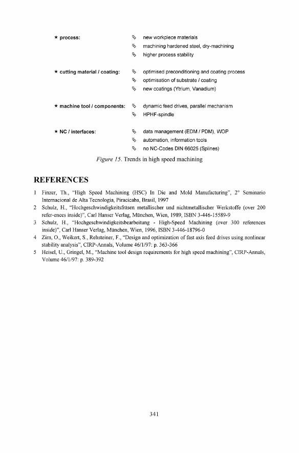
* process:
* cutting material 1 coating:
* machine tool 1 components:
* NC 1 interfaces:
new workpiece materials
machining hardened steel, dry-machining
higher process stability
optimised preconditioning and coating process
optimisation of substrate 1 coating
new coatings (Ytrium, Vanadium)
dynamic feed drives, parallel mechanism
HPHF-spindle
data management (EOM 1 POM), WOP
automation, information tools
no NC-Codes DIN 66025 (Splines)
Figure 15. Trends in high speed machining
REFERENCES
Finzer, Th., "High Speed Machining (HSC) In Die and Mold Manufacturing", 2° Seminario
IntemacionaI de Alta Tecnologia, Piracicaba, Brasil, 1997
2 Schulz, H., "Hochgeschwindigkeitsfrfisen metallischer und nichtmetaIlischer Werkstoffe (over 200
refer-ences inside)", Carl Hanser Verlag, Miinchen, Wien, 1989, ISBN 3-446-15589-9
3 Schulz, H., "Hochgeschwindigkeitsbearbeitung - High-Speed Machining (over 300 references
inside)", Carl Hanser Verlag, Miinchen, Wien, 1996, ISBN 3-446-18796-0
4 Zim, 0., Weikert, S., Rehsteiner, F., "Design and optimization of fast axis feed drives using nonlinear
stability analysis", CIRP-Annals, Volume 46/1/97: p. 363-366
5 Heisel, U., Gringel, M., "Machine tool design requirements for high speed machining", CIRP-Annals,
Volume 46/1/97: p. 389-392
341